Abstract
Closed-cell aluminum foam has a porous structure and metal properties due to its unique composition. As a structural material, it has the advantages of being lightweight, having a large specific surface area, and having high specific strength and stiffness. As a functional material, it can be used for sound and noise reduction, heat insulation, electromagnetic shielding, damping, and energy absorption, but it also has poor mechanical properties and poor surface flatness, and can be easily corroded. Considering the abovementioned problems, researchers have gradually extended their research on foam materials. Under the research of many international scholars, studies have shifted from simple aluminum foam preparation to improving and optimizing aluminum foam composite structures (AFCSs). From the perspective of development prospects, AFCSs have better application prospects than single aluminum foam. In this paper, the research progress on the preparation technology of AFCSs in recent years was reviewed based on the performance enhancement mechanism of aluminum matrix composites and the structural characteristics of aluminum foam. The morphology and pore structures of closed-cell AFCSs under different preparation methods were summarized. However, due to the limitations of existing experimental conditions, this paper only considered the advantages and disadvantages of AFCS preparation methods. The improvement of AFCS preparation technology, the development of the potential properties of AFCSs, and the promotion of AFCS industrial applications were also considered.
1. Introduction
Traditional solid foam materials, such as polymer foam and honeycomb aluminum sheets, have yet to meet the needs of today’s social development due to their limitations (low strength and poor high-temperature resistance, etc.). This has brought the research on foamed metals, especially foamed aluminum material, back into the view of scientists and various enterprises. As a new type of composite material, closed-cell aluminum foam is lightweight, has high specific stiffness, high energy absorption, and excellent electromagnetic shielding and damping. As the research progressed, various sheets, tubes, and metal frames were inserted into aluminum foam from the outside or inside to form aluminum foam composite structures (AFCSs) [1,2,3]. AFCSs have many advantages over traditional aluminum foam. AFCSs are stronger than thick sheets of the same mass. Their main advantage over bare foam without panels is that external panels enable AFCSs to withstand larger tensile loads. Aluminum foam is reinforced with wire or mesh, similar to sheet reinforcement, with both resulting in better tensile properties. The presence of sheets and pipes can avoid the surface damage or corrosion problems of aluminum foam. Based on the abovementioned advantages, people are increasingly interested in AFCSs, and several methods of making AFCSs have been proposed. According to the production technology, this occurs mainly through the direct foaming method and the indirect foaming method [4,5,6,7]. During the indirect foaming method, core materials fabricated by powder metallurgy and the melt foaming method are cut into various shapes and AFCSs are prepared by assembling aluminum foam cores and external structures, with some binder being sometimes necessary. To obtain suitable interfaces between the aluminum foam and the external structure, the foamable aluminum melt is poured inside metal tubes or some other cavity structures, where the internal surfaces of the cavity structures are pretreated. Based on the above fabrication route, various kinds of AFCSs have been created, such as the aluminum foam sandwich. This paper will summarize the preparation methods of several aluminum foam composite structures. AFCSs have been widely used in real life [8], such as in lightweight structures, packaging, insulation, shock absorption, noise reduction, and in other fields. Based on the review’s focus, this paper only briefly puts forward the application of AFCSs and does not systematically introduce their applications.
2. Aluminum Foam Sandwich
The aluminum foam sandwich (AFS), a typical AFCS, is composed of external solid panels and an internal porous aluminum foam core. According to the service conditions and manufacturing method, titanium, steel, aluminum, wood, ceramic, carbon fiber, and other materials [9,10,11,12] can serve as the above-mentioned solid panels, as shown in Figure 1. The porous aluminum foam core has poor mechanical performance, but the external solid panels of the AFS can bear the main load to protect the core from being destroyed during a crash. At the same time, the aluminum foam core increases the distance between the two solid plates, thereby increasing the second-moment area of the AFS. As a result, the structural stiffness and strength increase. In addition, external deformation energy can be consumed by plastic deformation of the porous aluminum foam core. From the lightweight structure perspective, the low-density aluminum foam core significantly reduces the mass of the AFS, leading to high specific strength and specific stiffness.
Figure 1.
AFSs prepared by different panel materials: (a) aluminum, reprinted with permission from ref. [13]. Copyright 2022 Elsevier, (b) steel, reprinted with permission from ref. [14]. Copyright 2022 Elsevier, (c) epoxy resin, reprinted with permission from ref. [15]. Copyright 2022 Springer Nature, and (d) carbon fiber, reprinted with permission from ref. [16]. Copyright 2022 John Wiley and Sons.
At present, the preparation methods for AFSs are divided into adhesive bonding, welding, powder metallurgy, and surface compaction methods. Owing to the various fabrication routes, the porosity, uniformity, and mechanical properties of the AFS can be vastly different.
2.1. Adhesive Bonding Method
Adhesive bonding is the most direct and effective method to combine the panels and the aluminum foam core, and this method also has the advantages of high efficiency and low cost. The primary preparation process includes the following steps. Firstly, the bonding surfaces of solid panels and aluminum foam core surfaces are polished using sandpaper, ensuring superficial roughness. Secondly, the preprocessed panels and aluminum foam core are cleaned with ethanol or acetone to remove oil and impurities. Thirdly, an adhesive is applied to the preprocessed surface, and these parts are combined under certain temperatures and pressures [17].
Figure 2a shows the assembly diagram for a steel–foam–steel AFS using work fixtures, where the adhesive was epoxy resin. A schematic diagram for the cross-section is shown in Figure 2b. From the perspective of the fabrication process, an adhesive was necessary, so the bonding strength between the panels and the core was influenced by the quality of the adhesive. Additionally, polymer binders are easily weathered after long-term use and will lose their efficacy under high temperatures. From the perspective of the bonding surfaces, a porous structure causes a rugged bonding surface, so only the skeleton area can contact a solid panel during an appropriate pressure, and the effective bonding surface is insufficient. Concave pore surfaces are difficult to clean, and grease, scraps, and cutting liquid adhere to the pore’s inner surface, weakening the bonding strength. To improve the bonding strength of the AFS, many scholars have adopted various modification methods to treat both the panel and aluminum foam core surfaces, and a high-temperature adhesive method has also been employed. For example, nitrogen plasma has been used to pretreat aluminum foam and aluminum plates to increase the surface hydrophilicity of the aluminum and the adhesive [18]. Surface modification methods, such as silane treatment and silane treatment combined with a polypropylene base film addition, have been used to bond fiber–metal laminates and Al foam. An AFS with aluminum alloy sheets fabricated using an improved bonding process with an epoxy adhesive [19] showed excellent bonding strength, and the whole AFS presented superior compression and energy absorption properties [20]. Replacing traditional adhesives with high-temperature adhesives [21] can improve the high-temperature mechanical properties of the AFS. AFSs prepared directly with carbon fiber/epoxy composite laminates as the upper and lower panels also have certain bonding strengths [11,22].
Figure 2.
Sample bonding diagram: (a) adhesive assembly drawing [23] and (b) adhesive detail diagram [24]. Reprinted with permission from ref. [23,24]. Copyright 2022 Elsevier.
Adhesive technology only influences the bonding strength between the core and panels, the internal pore structures of the AFS are controlled by the aluminum foam core, which is formed by slicing the aluminum foam bulk. In other words, the pore morphology of the AFS is mainly related to the aluminum foam bulk preparation method. To date, aluminum foam cores have been mainly prepared by employing the melt foaming method. Figure 3 shows the aluminum foam core with different densities. The pores of aluminum foam samples prepared by melt foaming technology have gradient characteristics, and aluminum foam core layers with different pore sizes can be obtained by cutting aluminum foam samples at different heights. The average pore size is 6.5, 4.5, and 3.2 mm in Figure 3a–c, respectively. It can be observed that the aluminum foam core presents uniform pore structures. Figure 4 shows an AFS prepared by the adhesivity method, where there is an obvious gap between the panel and core.
Figure 3.
Appearances of aluminum foam cores with various relative densities [25]: (a) 0.11, (b) 0.16, and (c) 0.20. Reprinted with permission from ref. [25]. Copyright 2022 Elsevier.
Figure 4.
Cross-section of an AFS prepared using the adhesive bonding method [26]. Reprinted with permission from ref. [26]. Copyright 2022 Elsevier.
In conclusion, the internal aluminum foam core contributes to the functional properties, the external solid panels bear the main loading, and the bonding area acts as a middle layer transferred load. Therefore, many scholars have exhausted improving adhesive technology to improve the bonding strength, and the most widely used adhesives are AB adhesives, polycarbonate resin, and epoxy resin. Despite this, due to the properties of the polymer adhesive itself, melt and metamorphism limits the adhesive’s working conditions. Although some certain high-temperature adhesives can adapt to short-term high-temperature environments, the aging phenomenon exacerbates inevitably during long-term use, and their application is limited [27,28].
2.2. Welding Method
Welding, known as an industrial tailor, has been widely used to join metal materials; in this regard, welding can also be applied to joint aluminum foam core and metal panels for fabricating an AFS. The main welding methods for AFSs include brazing, diffusion welding, and friction stir welding [29,30,31].
2.2.1. Brazing
Solders are necessary for braze welding, which are molten and fill the weld area [32,33]. Under certain welding conditions, the brazing method can achieve the metallurgical bonding of an aluminum foam core and sheet metal. The main technological processes are similar to the adhesive bonding method. Firstly, both the core and panels are cleaned to remove the oxide layer and grease. Then, solders are inlaid on one side of the panel and flux aqueous solution is sprayed. Finally, the combined core and panels are placed in a brazing furnace filled with nitrogen [2,34].
The holding temperature and time during the brazing process are key factors in the joint quality. Experimental results show that if the brazing time is too long many Al/Fe intermetallic compounds are produced in the joint. These brittle phases reduce the shear strength of the joint, and the mechanical properties of the AFS materials are affected [35,36]. Additionally, improving the solder’s wetting and diffusion behavior can effectively increase the bonding strength between the aluminum foam and the panels, achieving joints with high bending strength [37]. Based on the above discussion, an AFS prepared with zinc-based solders has shown good bending properties [34].
Metallurgical combination is generated when a suited solder is added during high-temperature brazing for fabricating an AFS. Simultaneously, some defects appear in the brazing joints if the brazing temperature is high. Oxide layers generated on the bonding surface under high temperature, coupled with the changed wettability because of a covered oxide layer, are the key factor. In general, reducing the oxidation of joints can improve brazing quality. Based on the above discussion, Wan et al. [38] adopted the slag-free brazing method to prepare an AFS. The experimental results show that the aluminum foam core and panel produce metallurgical bonding without stratification. Figure 5 shows the fabrication and interfacial characterization of the aluminum foam sandwich via fluxless soldering with surface abrasion [38]. Despite the welded AFS presenting good quality at the brazing joints [39], an incomplete melting of the solder layer and an overburning of both the panels and core material can easily occur during high-temperature brazing [36]. Despite this, the pore morphology of fabricated AFS is similar using this method to that fabricated using the adhesive method, as the core material preparation route is the same.
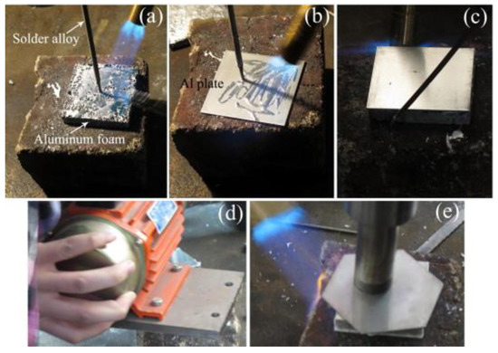
Figure 5.
Process of fluxless soldering with surface abrasion assisted by different vibration modes [38]: (a) molten solder coated on aluminum foam, (b) molten solder coated on Al plate, (c) Al plate covered on aluminum foam, (d) mechanical vibration, and (e) ultrasonic vibration. Reprinted with permission from ref. [38]. Copyright 2022 Elsevier.
All in all, the temperature, time, solder, cleaning, and heating method are the main control parameters for brazing AFSs, and many scholars have devoted energy to improving bonding strength between the panel and the aluminum foam core. Due to the joint quality and low cost, the brazing method for AFS fabrication presents a potential industrial application. Brazing is widely used in industry and is suitable for welding components that are precise, complex, and composed of different materials, such as honeycomb structural plates, turbine blades, carbide cutting tools, and printed circuit boards.
2.2.2. Diffusion Welding
Diffusion welding is performed at a certain temperature and pressure, with atoms diffusing at the interface and forming a strong joint. A vacuum or a protective atmosphere is necessary. Microplastic deformation (solid-phase diffusion) or the micro-liquid of the welding surface (liquid-phase diffusion) promotes atomic diffusion. In preparing the AFS, atoms are diffused between the panel and the core to form metallurgical connections [40]. During the diffusion welding process, microplastic deformation occurs first at the interface under pressure, and, as a result, the contact area gradually expands. Atom interdiffusion at the expanded contact area forms a bonding area. With increased holding time, atomic diffusion gradually develops to the deep layer, generating intermetallic compounds and achieving reliable joints.
For preparing an AFS, transient liquid diffusion welding is more suitable compared with solid-phase diffusion, because the latter method requires high surface quality and a long holding time [41]. Experimental results have showed that the fatigue life of an AFS prepared by ultrasound-assisted liquid diffusion welding is much longer than that prepared by the adhesive bonding method [42]. Open-cell AFS has been successfully fabricated using the vibration-assisted liquid bonding method; shear tests showed that vibration could significantly improve the bonding quality [43]. Despite this, solid-phase diffusion welding for preparing an AFS has its advantages, such as good bonding strength and it does not melt metal [44].
2.2.3. Friction Stir Welding
Friction stir welding [45], regarded as a solid-state bonding technology, has been used widely in welding dissimilar materials [46]. A schematic diagram for preparing an AFS using friction stir welding is shown in Figure 6. During friction stir welding, the high-speed rotated stirring head is started, and then the cylindrical stirring needle is squeezed into the combined plates until the shaft shoulder contacts the panel [47]. Mechanical energy from the stirring needle transfers into the thermal energy of the material, and powders in the combined plate cause plastic rheology and mixing. Different from other methods, both the foaming process of the core and the combining of the panel and the core are implemented at the same time during friction stir welding [48].
Research has shown fabricated aluminum foam complex-shaped parts with a uniform porous structure when the weld spacing, speed, and rotational speed were 3 mm, 50 mm/min, and 2000 r/min [49], respectively. An AFS prepared by friction stir welding presented excellent bending strength, impact protection performance, sound absorption, and reduction performance [50]. Hangai [51] prepared an aluminum foam/dense steel composite by friction stir welding; the mixing of the foaming agent and aluminum powders and the bonding between the aluminum precursor and steel were achieved simultaneously. Although the precursors formed a brittle intermetallic compound layer at the interface after heat treatment, these intermetallic compounds had a higher strength than that of the aluminum foam core. There are two typical reasons for the high bending strength of an AFS prepared by friction stir welding [52]: (i) the connection between the panels and the aluminum foam core is achieved through the plasticized metal flow without introducing new materials and (ii) friction stir welding refines the grain of the panel, leading to an improvement in the panel.

Figure 6.
Schematic diagram of AFS preparation through friction stir welding [50]. Reprinted with permission from ref. [50]. Copyright 2022 Elsevier.
Figure 6.
Schematic diagram of AFS preparation through friction stir welding [50]. Reprinted with permission from ref. [50]. Copyright 2022 Elsevier.

From the perspective of joining technology, friction stir welding can also be used for welding AFSs. A successfully prepared AFS using friction stir welding is shown in Figure 7. Due to high-speed rotation and movement of the stirring head, several small pores were generated at the core and panel mixing area [48]. For internal pore structures, the average thickness of the cell wall for the bonding areas was larger than that of the core material, and an obvious welding interface can be observed. Because of the random foaming, a few large inhomogeneous pores appeared after the agglomeration of foamable particles during the mixing process [53]. Welding marks can be observed on the outer surface of the panels.
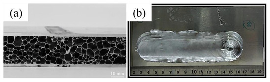
Figure 7.
(a) Cross-section of a friction-stir-welded AFS [48] and (b) metal panel of the FSW work piece [53]. Reprinted with permission from ref. [48,53]. Copyright 2022 Elsevier.
2.3. Powder Metallurgy Method
The main raw materials for fabricating an AFS using the powder metallurgy method are aluminum alloy powders, TiH2 particles, and metal panels. Before the foaming process, aluminum powders and TiH2 particles are mixed, and then the mixture is compacted into a foamable precursor with bilateral metal panels. In general, the key factor for fabricating an AFS is the bonding strength between the core and the panels, as well as the densification of the foamable precursor. The densification of the powder is mainly achieved by pressing, rolling, and wrapping rolling. At the same time, cold pressing or hot pressing is used, or two other kinds of technology are used simultaneously for powder preparation. In general, hot pressing is the most widely used method, as the main bonding mechanism of an AFS prepared by powder metallurgy is thermal diffusion [54].
The preparation of an AFS using powder metallurgy is limited by the densification of the precursor and the quality of the internal pore structure, also this method has the disadvantages of a high preparation cost and a small product size. To overcome these disadvantages, scholars have prepared AFSs by changing the pressing method and carrying out a lot of research [4,8,13].
2.3.1. Cold- and Hot-Pressing Powder Metallurgy Method
The cold- and hot-pressing powder metallurgy method is a widely used method for fabricating an AFS. The main processes [55] include mixing powder, cold pressing, hot pressing, and foaming, as shown in Figure 8. Appropriately extending the mixing time can improve the uniformity of the achieved AFS. The purpose of cold pressing is to form a bulk material from powders to transfer it from one mold to another, because the molds for cold and hot pressing are sometimes different. Hot pressing is a critical process to achieve a dense precursor core and a good bonding strength between the precursor core and the panels. The adjustable parameters are pressure, time, and temperature. Foaming is the last step, in which the density and pore size of the core can be controlled by adjusting the foaming time and temperature. Additionally, this process improves the bonding strength between the precursor core and the panels.
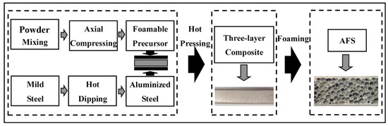
Figure 8.
Schematic diagram of fabricating an AFS using the cold- and hot-pressing powder metallurgy method [54]. Reprinted with permission from ref. [54]. Copyright 2022 Elsevier.
Results have shown that Al, Mg, and TiH2 with a purity of 99.7%, 99.0%, and 99.0%, respectively, can be used to produce aluminum foams by powder metallurgy technology. About a 400% expansion phenomenon was observed when the hot-pressing temperature and pressure were 490 °C and 8 MPa, respectively [54]. An excellent bonding area between the core and the panels with a high metallurgical quality [54] was obtained in this case. Ding [56] introduced a new method for preparing foamable AFS precursors by hot pressing. An AlMg4Si8 alloy was formed by mixing Al, AlMg50, and Si powders, and then 0.5 wt% TiH2 was added for foaming. It was found that the suitable preparation conditions were cold pressing and then hot pressing at 450 °C [8,57]. A tight metallurgical bonding layer between the panels and the core was generated as atom mutual diffusion was promoted under high temperatures. For example, iron from a steel panel was diffused with aluminum through the interface and formed FeAl3 [1], and titanium panels formed intermetallic compounds of TiAl3 and Ti2Al5 [58]. From another perspective, plastic deformation caused by hot pressing can also reinforce the bonding strength [59].
To improve the internal pore structures, the foaming technology of powder metallurgy was exhausted and studied [60]. By investigating the evolution process and dynamic mechanism of foamed samples during the foaming expansion process, the foaming process was divided into three stages, as shown in Figure 9. Stage I was the pore-forming stage, with TiH2 particles decomposing, and the generated gas pressure gradually caused some small pores. Stage II was characterized by pore growth and pore coalescence. During Stage III, the sample expansion stopped and started to shrink. Hence, controlling the foaming stage is key for fabricating high-quality pore structures.
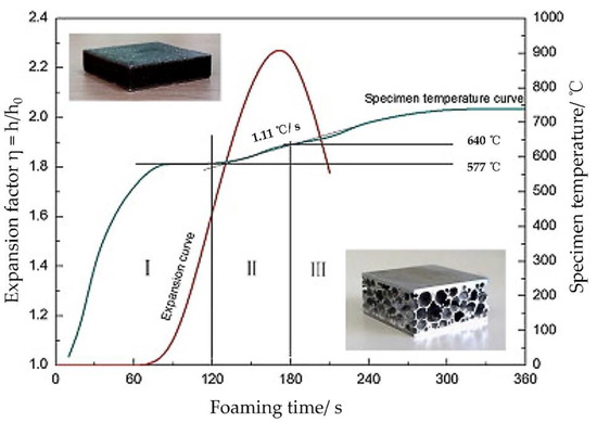
Figure 9.
Expansion and temperature curves vs. foaming time of an AFS [61]. Reprinted with permission from ref. [61]. Copyright 2022 Elsevier.
Figure 10a shows the final pore structure of foamable precursors obtained by an AFS under different pressures after foaming. Under different pressures, the pore structure after foaming is different due to the different densification degree of the core layer. As shown in Figure 10a, the precursor obtained at 50 MPa could not be fully foamed, and a large cavity was formed at 100 MPa [62]. Uniform foaming can be obtained at 200 and 300 MPa [62]. The microstructures of the precursor before and after foaming obtained by cold pressing and hot pressing is shown in Figure 10b,c, respectively. The precursor is dense before foaming, and a large number of uniform holes can be easily seen after foaming, but no foaming phenomenon occurs at the flange position [56,62]. In summary, an AFS prepared by cold-pressing and hot-pressing powder metallurgy methods has a clear internal structure, spherical and ellipsoid pores are found throughout the cross-section, and no apparent defects are detected at the bonding area. However, the density of the precursor and the homogeneity of the mixed powder influences the quality of the pores, leading to a large hole in the core. According to the characteristics of powder metallurgy technology, other metal powders are often added to improve pore structure quality. As shown in Figure 11, the composition of Sn, Cu, Mg, and Si powders can reinforce the mechanical properties by improving the pore size [63]. For example, the addition of Sn has a significant effect on reducing the pore size, and the addition of Cu can reduce the suitable foaming temperature. However, due to the limitation of pressure, manufacturing equipment, and complex production processes, the cold- and hot-pressing powder metallurgy method cannot meet the requirements of industrial large-scale production.
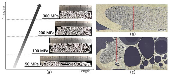
Figure 10.
Macroscopic morphology of an AFS [62]. (a) The final cellular structures of an AFS after foaming durations of 600 s at 640 °C of which foamable precursors were obtained under different pressures, (b) microstructure of the precursor obtained by cold prepressing and hot pressing under a pressure of 200 MPa, and (c) the cellular structure of the precursor after foaming. Reprinted with permission from ref. [62]. Copyright 2022 Elsevier.
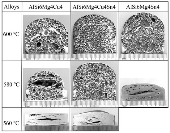
Figure 11.
Final pore structures of three different alloys after foaming at various temperatures [63]. Reprinted with permission from ref. [63]. Copyright 2022 Elsevier.
2.3.2. Rolling Powder Metallurgy Method
The densification process of this type of powder metallurgy method is rolling [64]; in this process, the panels and the mixed powders are compacted by extrusion and compound rolling to obtain a foamable precursor. Rolling is a continuous process, so the rolling powder metallurgy method is suitable for industrial production. To improve the densification of the precursor, the rolling process is usually implemented under high temperatures [65], and then the prepared precursor is heated in a furnace to an appropriate temperature for foaming. With the increased temperature, the precursor transforms to a semi-melting state, and the decomposition of TiH2 occurs at the same time; as a result, bubbles are generated. Simultaneously, atom diffusion occurs between the panel and the core, forming intermetallic compounds and achieving an ideal metallurgical bonding state.
Experimental results have verified that the rolling powder metallurgy method for preparing an AFS can obtain a higher densification of the core and present a better interface bonding strength [66] compared with the traditional hot-pressing method. Nevertheless, there are also some disadvantages in the rolling process. Flow and loss of core powder causes an uneven rolling force on samples, stress concentration is easily caused at the high-density area of the powder, and, as a result, cracks are generated. In addition, some micro-cavities can be observed in the low-density area. Large-sized TiH2 particles can cause some micro-cracks in the surrounding structure [67,68].
As shown in Figure 12, bubbles in the core layer are flat at the initial stage of foaming, and non-uniform pore structures appear in the later stage of foaming; meanwhile, rupture and coalescence are observed [69]. Adding 0.5−2.0 wt% of Mg into 1.0 wt% TiH2 particles and Al–Si alloy powder can effectively relieve crack and powder agglomeration during the foaming process, with an optimal rolling reduction rate of 60−70% [69].
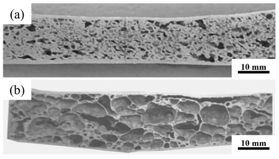
Figure 12.
Macro morphology of foamed samples at different foaming stages: (a) the initial stage and (b) the later stage [69]. Reprinted with permission from ref. [69]. Copyright 2022 Springer Nature.
The rolling powder metallurgy method can continuously realize the preparation of large-sized AFSs, the prepared precursor has high densification, and there is a high bonding strength between the panels and the core. The agglomeration of foaming agents can be effectively solved by controlling the foaming temperature, rolling pressure, foaming agent content, and powder mixing process.
2.3.3. Jacketing Rolling Powder Metallurgy Method
To solve the powder loss problem, the jacketing rolling powder metallurgy method was put forward based on the rolling powder metallurgy method; the specific process is shown in Figure 13. An AFS prepared using the jacketing rolling powder metallurgy method has the characteristics of good powder uniformity and high shape accuracy [70]. Jacketing rolling [71] can effectively improve the density of the precursor, and the powder utilization rate is close to 100%. Despite this, as shown in Figure 14, a thick dense aluminum layer appears on the vertical edge of the AFS after foaming. Compared with the traditional rolling powder metallurgy method, an AFS prepared using the jacketing rolling method has more uniform pore structures, and the cross-section of the AFS is dominated by small pores.
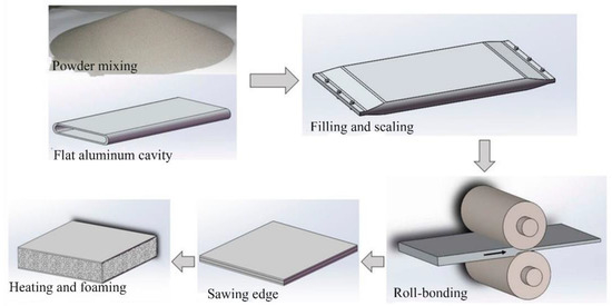
Figure 13.
Preparation processes for fabricating an AFS using the jacketing rolling powder metallurgy method [72]. Reprinted with permission from ref. [72]. Copyright 2022 MDPI.
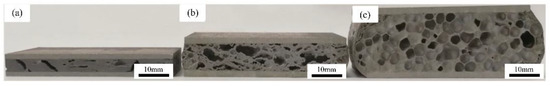
Figure 14.
Macro morphology of AFS samples prepared by the jacketing rolling method, with rolling temperatures of (a) 20 °C, (b) 250 °C, and (c) 400 °C [72]. Reprinted with permission from ref. [72]. Copyright 2022 MDPI.
Experimental results have verified that an AFS prepared by the jacketing rolling method has excellent metallurgical bonding between the core and the panels and can withstand a higher bending load [73]. Song [74] successfully prepared an AFS sheet using air-atomized 99.0 wt% AlSi12 powders, 1.0 wt% Mg powder, and 1.0 wt% TiH2 powder as raw materials when employing the jacketing rolling method; the results illustrated that jacketing rolling can effectively prevent the crack propagation of the panel. Sun [72] studied the influence of the rolling temperature on the preparation of AFS precursors by the jacketing rolling method; the experimental results showed that precursors with excellent density and an excellent bonding interface were prepared at the rolling temperature of 400 °C. Wang [61] introduced a melting process of an AFS powder block based on the jacketing rolling method; the prepared AFS appeared to have an excellent cellular structure and excellent mechanical properties when the optimal reduction rate was 80%, the relative density was more than 0.98, and the material utilization rate was close to 70%.
2.3.4. Other Methods
Based on the powder metallurgy method, Kitazono [75] proposed a novel practical technique for fabricating closed-cell aluminum foam plates using cumulative roll welding (ARB). Hosseini [76] prepared an AFS using continuous annealing and roller compression (CAR). These two methods realized the preparation of the AFS and the main routes for ARB and CAR were roughly the same. As shown in Figure 15, the main processes are divided into two steps. Firstly, a stack of pretreated aluminum strips is prepared, then stacking strips and certain TiH2 particles are added between each of the two strips, after that the stacked strips are rolled together. The second step is a repeat loop to ensure the home dispersal of the TiH2 particles. The rolled strips are cut into two or several pieces and surface treatment is performed, then the treated strips are stacked together and rolled together again. After repeating this process for about the 8th cycle, a foamable precursor is prepared. The foaming process of the precursor is similar to other powder metallurgy methods.
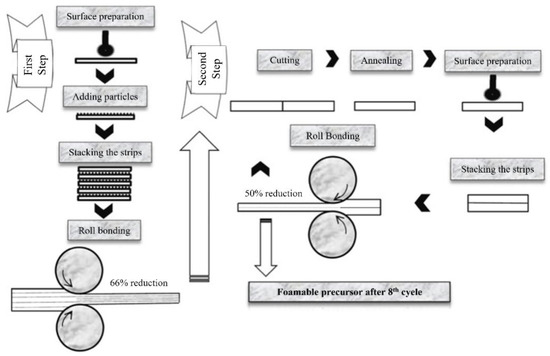
Figure 15.
Schematic illustration for fabricating a foamable precursor via the CAR method [77]. Reprinted with permission from ref. [77]. Copyright 2022 Elsevier.
Although ARB and CAR can be used for fabricating large-sized AFSs, the uniform dispersion of the foaming agent between each strip is a problem, leading to AFS samples having a deficient pore structure, such as large pores and extremely uneven pore distribution [75,76]. Adding 0.75 wt% SiC particles to the foamable precursor can reduce the size of the pores and the uniformity and roundness of the pore structure can also be improved; however, the smooth surface of the aluminum foam plate becomes degraded [76], as shown in Figure 16.
Figure 16.
Macroscopic structures of an aluminum foam plate [76] (a) without and (b) with SiC particles. Reprinted with permission from ref. [76]. Copyright 2022 Elsevier.
2.4. Melt Foaming Method
Melt foaming is the most widely used method for making bulk aluminum foams. By dispersing a TiH2 foaming agent into the thickened aluminum solution, aluminum foam is prepared by rotating the blades at high speed and combining aluminum foam with panels in different ways for a prepared AFS. On this basis, it is mainly divided into two routes. The first implants two panels into a foamable aluminum melt [12] or cures a foamable aluminum melt into a specific mold [78], and the TiH2 particles decompose and fill the space between the two panels, as shown in Figure 17a. The other route is hot pressing panels with a foamable precursor [1], called the two-step foaming method, using the melt foaming method, as shown in Figure 17b. Compared with the powder metallurgy and welding methods, the panels and the aluminum foam core of the AFS using the melt foaming method are joined by transient liquid diffusion. Little metallurgical bonding is formed in the bonding area, so this method can effectively solve the sample size problem. Different from the secondary processing of the powder metallurgy method, it is expected to realize the direct formation of an AFS and presents great potential for application in industrial production.
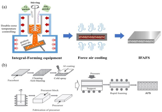
Figure 17.
Schematic diagram of a melt-foaming-fabricated AFS, (a) pouring method 1 and (b) two-step foaming method. [1,79]. Reprinted with permission from ref. [1,79]. Copyright 2022 Elsevier.
A melt-foaming-fabricated AFS showed a metallurgical bonding layer at the interface between the core and the panels, and the thickness of the bonding layer increased with an increased holding time. Ternary phase Al20CaTi2 and binary phase Al2Ti were detected in this bonding layer [12]. Regarding the two-step foaming method, a new slow-released foaming agent appeared to have excellent performance, as it presented a low loss rate in the early stage and a high foaming efficiency in the late stage [80]. The melt foaming method for fabricating an AFS has the characteristics of a short process, relatively uniform pore structures, sufficient bonding strength, and less limits in the specimen size. Therefore, a melt-foaming-fabricated AFS has great potential and will be competitive in the future.
All in all, the external panels greatly improve the bearing capacities of single aluminum foam, and the internal aluminum foam core has damping shock absorption, sound absorption, noise reduction, heat insulation, electromagnetic shielding, and other excellent performances [81,82,83]. Hence, AFS structures appear to have great potential in aerospace, marine and automobile transport, rail transport, and other fields, and the AFS structure is also one of the materials widely studied by many countries [84,85].
3. Aluminum-Foam-Filled Tube
An aluminum foam-filled tube (FFT) is fabricated by filling a thin-walled metal tube with multifunctional aluminum foam; just as in the preparation method of AFSs, the interface between the tube and the foam core appears in various fabricating routes. Because of the special composite structure of the FFT, filled aluminum foam prevents the inward buckling deformation of the metal tubes, leading to excellent load-bearing capacities. The dense metal tube makes up for the less porous core material and delays the rupture of the foam core. The interaction between the aluminum foam core and the metal tube not only solves the poor mechanical properties of the aluminum foam when used alone but also overcomes the problems of the poor non-axial bearing capacity of the thin-walled tube. According to the interface fabricating approach, the FFT preparation method is classified into ex situ and in situ preparation methods [7,86,87,88], as shown in Figure 18. The in situ preparation method is a method that synchronizes the foam-forming process with the combination of the core material and pipe wall. The aluminum foam and the thin-walled metal tube in the ex situ preparation method are prepared independently. Then, the aluminum foam and the metal thin-walled tube are cut according to the matching size. Finally, the combination of the aluminum foam core material and metal thin-walled tube is realized. The most widely used cross-sections of filled tubes are round and square [3,89,90,91]; also, some single-tubes, double-tubes, and multi-tubes are embedded with aluminum foam for fabricating the FFT, as shown in Figure 19.
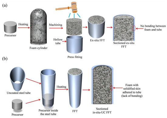
Figure 18.
Schematic illustration of the FFT fabrication of (a) ex situ and (b) in situ foam filling [86]. Reprinted with permission from ref. [86]. Copyright 2022 Elsevier.
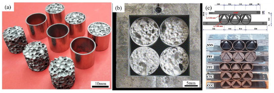
Figure 19.
Some prepared FFTs: (a) aluminum-foam-filled circular tubes [92], (b) square-packed multi-tube designs [93], and (c) aluminum-foam-filled inlaid tubes [94]. Reprinted with permission from ref. [92,93,94]. Copyright 2022 Elsevier.
3.1. Ex Situ Filling Method
Similar to the method described above for the adhesive preparation of AFSs, the preparation of the aluminum foam core and the thin-walled tube is carried out independently. Wire electrical discharge machining is the most widely used method for cutting the aluminum foam core. After necessary cleaning, the prepared aluminum foam core is assembled inside the tube, the internal surface of which is pretreated. To fill and improve the interface of the core and tube, thermal expansion bonding, mechanical bonding, and adhesive bonding methods are employed. Among these methods, mechanical bonding is the most direct and easiest fabricating method. The key factor is interference fitting between the core and tube. Using adhesive to fill the gap between the core and tube is similar to the preparation of an AFS.
To investigate the fabrication methods for FFTs, scholars have devoted time and energy to research. Experimental results have showed that the thermal expansion bonding method cannot compensate for the surface error of the core, and a weak connection between the tube and core occurs. Compared with adhesive bonding, mechanical bonding cannot overcome the stress and strain from micro-distortion [95]. Duarte [96] prepared FFTs using powder metallurgy foaming technology and found that the interface area between the metal tube and core had excellent joint quality when using fasteners. These prepared FFTs can be used under high temperatures or strong corrosion conditions. The jointing strength was verified to be improved compared with samples prepared by the direct filling method. However, the connection through fasteners not only increases the quality of the packed structure but also leads to stress concentration in the connection area, which is prone to local failure after loading.
Figure 20 shows some FFTs prepared using the ex situ approach, where the aluminum foam cores were fabricated using melt foaming technology and powder metallurgy foaming technology. From Figure 20a, the aluminum foam core of FFTs prepared using melt foaming technology appears to have a relatively uniform pore structure, and its shape is mostly round or oval [97]. However, in Figure 20b, the core prepared using powder metallurgy technology shows an uneven pore structure and irregular shape [98]. Additionally, obvious macroscopic gaps between the aluminum foam core and the metal tube were detected.

Figure 20.
FFTs prepared using the ex situ approach: (a) melt foaming technology [97] and (b) powder metallurgy technology [98]. Reprinted with permission from ref. [97,98]. Copyright 2022 Elsevier.
To sum up, different ex situ FFT preparation methods have advantages and disadvantages. The thermal expansion bonding process is simple and low cost. However, due to the unique cellular structure of the aluminum foam core, there is a large surface error in the bonding process, leading to a weak bonding strength between the aluminum foam core and the metal tube. Adhesive bonding can improve the bonding strength effectively, but the existence of adhesive prevents the FFT from being used in high temperatures and other harsh environments. Using mechanical bonding such as fasteners will increase the quality of the filled structure but cannot overcome the stresses and strains caused by micro-deformation. Brazing and other welding technology require excellent substrate surface cleanliness, and welding technology is unsuitable for mass-produced FFTs because of its slow forming speed and high cost.
3.2. In Situ Preparation Method
The in situ preparation method means that the aluminum foam core and the bonding interface between the foam core and the metal tube are prepared in the same process. Therefore, powder metallurgy technology is the most used route. The main in situ preparation methods include powder mixing, densification, foaming and filling, and cooling. In most cases, the foamable precursor is transferred into a metal tube and foaming is conducted at high temperature.
The difference between the friction stir welding powder metallurgy foaming method [97] and the traditional in situ foaming method is that metallurgical bonding is formed before foaming. Studies have showed that FFTs with an in situ fabricated AlSi12 foam core appear to have excellent energy absorption capacity and a durable boundary layer formed between the matrix core and the tube inner wall [99]. By comparing the in situ and ex situ FFT preparation methods, experimental results have confirmed that in situ FFTs have a more stable and controllable deformation and stronger energy absorption capacity [94,100]. Zare [101] mixed Al powder with 0.6 wt. % TiH2 particles and achieved the preparation of a FFT (using steel tube) using the in situ foaming method. The prepared FFTs appeared to have a fine pore structure and the energy absorption of the FFTs was higher than the sum of the steel tube and the aluminum foam. Strano [102] prepared in situ FFTs (square tube) and studied their damping stability and bending performance. The results showed that the damping properties of an FFT change (improve) with the number of cycles, while all other dynamic properties are nearly constant. Taherishargh [103] fabricated a new type of FFT through a highly reproducible and cost-effective in situ process and implemented quasi-static uniaxial compression tests on foam, empty tubes, and FFT samples. The experimental results showed that the thickness of the tube wall played a key role, the energy absorption capacity of both the hollow tubes and the FFT samples increased with an increased tube thickness, and the FFTs showed excellent improvement in their energy absorption capacity.
Figure 21 shows the cross-section morphologies of ex situ and in situ fabricated FFTs; the aluminum foam cores were fabricated using the powder metallurgy foaming method. A macroscopic gap can be seen between the core and the tube, especially in the ex situ fabricated FFT [87,103], as shown in Figure 21a,c.
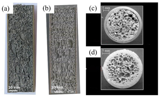
Figure 21.
Sectional and transversal view of (a,c) ex situ and (b,d) in situ FFTs [87,103]. Reprinted with permission from ref. [87,103]. Copyright 2022 Elsevier.
In conclusion, the in situ foaming preparation method is designed to fill the metal tube by using the volume expansion of the foaming precursor. A high-temperature environment during the foaming process promotes the generation of the bonding area between the metal tube and the foam. Therefore, FFT specimens prepared by the in situ preparation method have improved mechanical properties.
3.3. Other Methods
To realize the continuous production of FFTs, Peng [104] put forward a new method for fabricating FFTs based on the traditional gas injection foaming method, as shown in Figure 22. Reverse extrusion and continuous casting process technology were employed in this method.
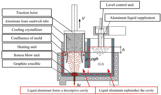
Figure 22.
Schematic diagram of bottom blowing and back extrusion composite preparation process [104]. Reprinted with permission from ref. [104]. Copyright 2022 Journal of Yanshan University.
As a new composite structure, the FFT has potential excellent advancements in impact absorption. Therefore, the FFT has great application potential in automobile manufacturing, aerospace, and rail traffic industries, such as the electric car battery pack shell, door thresholds, the car A-pillar, aluminum-foam-filled wings, and the train collision protection box.
4. Metal Grid Structure Enhanced Aluminum Foam
Dense metal materials cover the outside of the AFS and FFT structures. These existing panels or tubes can protect the weak aluminum foam core from destruction, improving mechanical performance. To date, scholars have carried out many experimental analyses and simulation studies [105,106,107,108], which have played a critical role in the application of AFS and FFT structures in the industrial field. Despite this, owing to the external dense metal materials, the whole density of the AFS and the FFT can be significantly enhanced.
In order to give full play to the lightweight advancement of AFCSs and ensure the functional performance of porous structures, the fabrication of metal grid structure enhanced aluminum foam (MGS-AF) has been put forward [109].
An MGS-AF was successfully prepared using the melt foaming method, and the main processes are listed as follows (as shown in Figure 23) [109,110]: First, the MGS was prepared by bending and welding 2D metal mesh. Then, the prepared MGS was assembled inside a mold and preheated at 720 °C. Next, a foamable aluminum melt was prepared using the traditional melt foaming method. After that, the foamable melt was poured inside the mold, the mold was closed and preserved at 710 °C for 3 min. Finally, the mold was cooled by using the water spray method, and the MGS-AF was obtained by cutting.
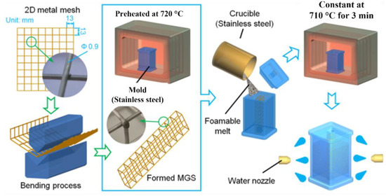
Figure 23.
Schematic diagram of MGS-AF preparation based on the melt foaming method [109]. Reprinted with permission from ref. [109]. Copyright 2022 Elsevier.
The fabrication method of MGS-AF can be divided into internal and external enhancement approaches. Figure 24a shows a photograph of an internally enhanced MGS-AF, where the bright central area represents the stainless-steel wire of the MGS with a diameter of 0.9 mm. The gray and black areas surrounding the wire are the aluminum matrix and pore, respectively. The metal wires of the MGS embedded in the aluminum foam were wrapped by a layer of aluminum matrix with a thickness ranging from 80 to 120 μm. This cladding layer and the MGS wire were located at the junction of the three bubbles, named the plateau border. The bending experimental results showed that the failure mode of the MGS-AF changed from a single tensile failure to composite tensile and compression loss.
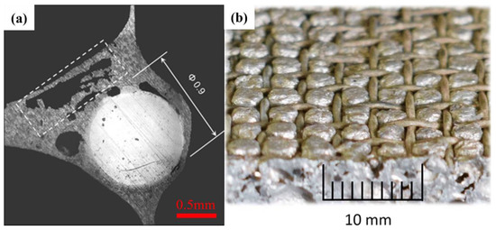
Figure 24.
MGS-AF samples fabricated using (a) internal [110] Reprinted with permission from ref. [110]. Copyright 2022 Materials and Manufacturing Processes. and (b) external [9] enhancement approaches. Reprinted with permission from ref. [9]. Copyright 2022 Springer Nature.
Formisano [9] discussed the preparation of an external stainless-steel-wire enhanced MGS-AF, as shown in Figure 25, where the aluminum foam was fabricated using the powder metallurgy method. Figure 24b shows the image of the externally enhanced MGS-AF. The metal mesh was distributed on both sides of the aluminum foam core, and the core layer was expanded and embedded inside each cell of the metal mesh during the foaming process. The results from the quasi-static three-point bending test showed that the MGS-AF had a beneficial effect on the mechanical properties compared with the original aluminum foam. Durante [111] also manufactured MGS-AF based on powder metallurgy method technology, and the bending load-bearing capacity was significantly improved.
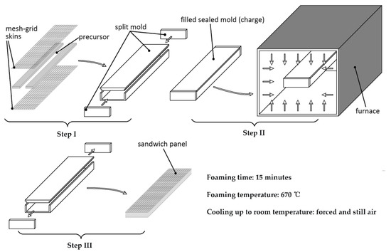
Figure 25.
Schematic diagram of preparing an externally enhanced MGS-AF based on the powder metallurgy method [9]. Reprinted with permission from ref. [9]. Copyright 2022 Springer Nature.
A composite sandwich structure composed of a metal frame and aluminum foam can further improve impact protection. Therefore, MGS-AF has a unique advantage in the field of weapon manufacturing, such as detecting tank ammunition cover foreign currency, the body outer wall steel plate, and the airdrop box. It has multiple functions, such as being lightweight and shockproof and having waterproof performance and a long service life.
5. Advanced Pore Morphology Foam-Filled Composite Structure
The critical component of an advanced pore morphology (APM) foam-filled composite structure is the aluminum foam ball, which has a spherical appearance and many elliptic pore internal structures. The APM aluminum foam ball appears to have a highly repeatable geometric structure and can overcome the disadvantages of unpredictable mechanical properties caused by the random foaming process [88]. Different APM aluminum foams have similar mechanical properties, so random or regular arrangements can be carried out in the cavity formed by the dense metal to obtain an APM foam-filled composite structure (as shown in Figure 26) with specific performance. As discussed above, the stiffness and energy absorption capacity of the whole structure is improved. The APM foam filler is fabricated using the improved powder metallurgy method, with the finished filler appearing to have a porous internal structure with high porosity. Large-sized aluminum foam composite structures can be prepared by arranging these APM fillers. The primary preparation approach includes the following processes: Firstly, the mixed mixture is compacted into foamable tablets. Then, the tablets are preserved at high temperature to foam, rolling the prepared aluminum ball at the appropriate time. Finally, these APM foam fillers fill the tubes or some other hollow structures. Some adhesion agents are necessary to ensure the filling strength, as shown in Figure 27.
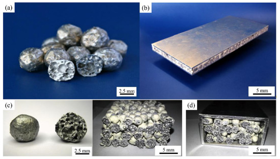
Figure 26.
APM composite structures: (a) aluminum foam ball filler, (b) APM sandwich composite structure [112], Reprinted with permission from ref. [112]. Copyright 2022 Elsevier. (c) APM composite foam, and (d) APM foam-filled composite structure [113]. Reprinted with permission from ref. [113]. Copyright 2022 Elsevier.
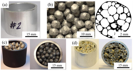
Figure 27.
(a) Thin-walled tube; (b) APM foam filler; (c) non-bonded APM foam-filled tubes; (d) polyamide-bonded APM foam-filled tubes [114]. Reprinted with permission from ref. [114]. Copyright 2022 Elsevier.
Duarte [114] prepared APM foam-filled tubes with polyamide by pouring APM foam balls coated with polyamide into empty aluminum alloy tubes. The compression results showed that polyamide-bonded technology significantly influenced the compression behavior of the APM foam-filled tube, and the specific energy absorption was substantially improved. Guo Qiayu [115] prepared aluminum–silicon alloy APM foam balls and fabricated APM sandwich composite structures by filling the hollow mold with these foam balls using epoxy coating adhesive and epoxy foam adhesive; the foaming and bonding mechanisms are analyzed here. Sulong [116] studied the mechanical properties of a single APM foam ball under quasi-static and dynamic compression loads; the experimental results showed that larger APM foam balls can bear higher compression loads. The mechanical strength of the APM foam ball was significantly improved because of the stressed-skin effect caused by its covered continuous skin.
The APM foam-filled composite structure, as a new type of filling material, has great application potential in many modern industrial fields. In addition to the applications requiring lightweight and high energy absorption and damping, it has gradually expanded to the application scenarios required by electromagnetic shielding, sound insulation, and noise reduction [89].
6. Summary and Prospects
The application of aluminum foam has become more extensive. From the perspective of development prospects, aluminum foam composite structures (AFCSs) have wider applications compared with single aluminum foam. However, some research has been limited in the laboratory scope. The preparation methods for AFCSs appear to have advantages and disadvantages. Therefore, future research should be focused on improving the AFCS preparation process, developing AFCSs’ potential properties, and promoting AFCS industrial applications.
- (1)
- Most scholars have conducted additional research on the foaming mechanism and the improvement of the pore structure of traditional aluminum foam. For example, Banhart’s team conducted an in-depth study on the foaming mechanism of aluminum foam based on X-ray and tomography [117]. An’s team revealed the stabilizing agent of non-thickening foaming technology to produce aluminum foam with a uniform internal structure [118]. In AFCSs, the addition of solid plates and pipes greatly influences the pore structure during aluminum foaming. For example, the powder loss caused by the pressing and rolling processes, the influence of coated rolling on powder uniformity, and the obstruction of the metal tube wall to core layer foaming during the in situ preparation of FFTs have an impact on the pore morphology and pore size of aluminum foam. Further research is needed.
- (2)
- Although the adhesive bonding method is simple, the bonding strength between the panels and the foam core is not strong enough. Adhesive aging limits the use of AFCSs in harsh conditions such as high temperatures. The surface modification of the panels and the foam core should be researched.
- (3)
- It is difficult to control the porosity of AFCSs fabricated using the powder metallurgy method, and the size of the samples is limited by the mold and equipment used. However, the powder metallurgy method has great advantages for preparing special-shaped AFCS parts.
- (4)
- The advantages of the melt foaming method have not been fully displayed, especially in fabricating large-sized and uniform pore structure AFCSs. The flowing, expanding, and filling properties of the foamable melt during the foaming process should be studied in depth.
- (5)
- The industrial production method of AFCSs with the shape of a sandwich plate, block material, and filling tube should be focused on, and the application fields need to be expanded.
- (6)
- The key to the AFCS preparation process is to realize the effective combination between the core material and the pipe, plate, metal mesh, or other structures and ensure the structural integrity of the aluminum foam core as far as possible during the combination process. Different methods of preparing AFCSs often have distinct advantages and disadvantages.
For AFSs and FFTs: (1) When the aluminum foam and the plate and pipe are prepared independently, other methods are usually needed to realize the connection between the aluminum foam and the plate and pipe. This method has the advantages of a simple operation and low cost. However, it is necessary to consider the influence of different technologies, such as the corrosion aging of adhesives, and fastener connection to increase the quality of the filling structure, e.g., brazing requires higher surface cleanliness. (2) When the aluminum foam forming process is synchronized with the combination of the plate and pipe, AFCSs prepared by such a method often have a strong binding strength. However, due to the simultaneous completion of foaming and bonding, the influence of the sheet and pipe on the pore structure of the aluminum foam molding cannot be avoided.
For MGS-AF: Because of the different insertion modes of the metal mesh, there are specific differences in appearance. However, the advantages of lightweight AFCSs are given full play, and prepared MGS-AF has a perfect pore structure.
For APM foam-filled composite structures: The binding of this usually requires the presence of an adhesive. Therefore, the adhesive aging and high-temperature resistance are its most significant shortcomings. However, this method has high repeatability, is a simple process, and is low cost.
The technical methods for preparing AFCSs and the more detailed advantages and disadvantages of each method are shown in Table 1.

Table 1.
Preparation processes and the advantages and disadvantages of the sample under each preparation process.
Author Contributions
Conceptualization, J.Z. and Y.A.; methodology, J.Z.; software, J.Z.; validation, J.Z., Y.A. and H.M.; formal analysis, J.Z. and Y.A.; investigation, J.Z., Y.A. and H.M.; resources, J.Z., Y.A. and H.M.; data curation, J.Z.; writing—original draft preparation, J.Z.; writing—review and editing, Y.A.; visualization, J.Z. and Y.A.; supervision, Y.A.; project administration, Y.A.; funding acquisition, Y.A. All authors have read and agreed to the published version of the manuscript.
Funding
This research was funded by the National Natural Science Foundation of China, grant number 51904179, and Shandong Provincial Key Laboratory of Precision Manufacturing and Non-Traditional Machining (grant number 9001/5322027). The APC was funded by the National Natural Science Foundation of China.
Data Availability Statement
Data are available on request from the authors.
Conflicts of Interest
The authors declare no conflict of interest.
References
- Liang, X.; Luo, H.; Lin, H.; Lu, X.; Wu, L. A Novel Method to Fabricate Steel-Al Foam Sandwich Panel with Metallic Bonding. J. Wuhan Univ. Technol.-Mater. Sci. Ed. 2019, 34, 1429–1432. [Google Scholar] [CrossRef]
- Shunmugasamy, V.C.; Mansoor, B. Flexural Response of an Aluminum Foam Core/Stainless Steel Facesheet Sandwich Composite. JOM J. Miner. Met. Mater. Soc. 2019, 71, 4024–4033. [Google Scholar] [CrossRef]
- Wang, T.; Shao, J.; Xu, T.; Wang, Z. Study on Axial Compression Properties of Aluminum Foam-filled Steel Tube Members After High Temperature. Iran. J. Sci. Technol. Trans. Civ. Eng. 2022, 46, 883–900. [Google Scholar] [CrossRef]
- Banhart, J.; Seeliger, H.W. Aluminium Foam Sandwich Panels: Manufacture, Metallurgy and Applications. Adv. Eng. Mater. 2008, 10, 793–802. [Google Scholar] [CrossRef]
- Baumgartner, F.; Duarte, I.; Banhart, J. Industrialization of powder compact foaming process. Adv. Eng. Mater. 2000, 2, 168–174. [Google Scholar] [CrossRef]
- Duarte, I.; Banhart, J. A study of aluminium foam formation—Kinetics and microstructure. Acta Mater. 2000, 48, 2349–2362. [Google Scholar] [CrossRef]
- Duarte, I.; Vesenjak, M.; Vide, M.J. Automated Continuous Production Line of Parts Made of Metallic Foams. Metals 2019, 9, 531. [Google Scholar] [CrossRef]
- Banhart, J.; Seeliger, H.W. Recent Trends in Aluminum Foam Sandwich Technology. Adv. Eng. Mater. 2012, 14, 1082–1087. [Google Scholar] [CrossRef]
- Formisano, A.; Durante, M.; Viscusi, A.; Carrino, L. Mechanical behavior and collapse mechanisms of innovative aluminum foam-based sandwich panels under three-point bending. Int. J. Adv. Manuf. Technol. 2021, 112, 1631–1639. [Google Scholar] [CrossRef]
- Han, M.S.; Bang, S.O.; Cho, J.U.; Lee, S.; Cho, C. Experimental study on the impact characteristics of a sandwich composite with an aluminum foam core. Int. J. Automot. Technol. 2013, 14, 61–66. [Google Scholar] [CrossRef]
- Yan, C.; Wang, J.; Song, X. Fatigue behavior and damage mechanism of aluminum foam sandwich with carbon-fiber face-sheets. J. Mech. Sci. Technol. 2020, 34, 1119–1127. [Google Scholar] [CrossRef]
- An, Y.K.; Yang, S.Y.; Zhao, E.T.; Huang, X. Diffusion Bonding in Fabrication TA2 Sheets Enhanced Aluminum Foam Sandwich. In Materials Science Forum; Trans Tech Publications Ltd.: Wollerau, Switzerland, 2017; Volume 898, pp. 950–956. [Google Scholar]
- Neu, T.R.; Kamm, P.H.; von der Eltz, N.; Seeliger, H.W.; Banhart, J.; García-Moreno, F. Correlation between foam structure and mechanical performance of aluminium foam sandwich panels. Mater. Sci. Eng. A 2021, 800, 140260. [Google Scholar] [CrossRef]
- Liu, H.; Cao, Z.K.; Yao, G.C.; Luo, H.J.; Zu, G.Y. Performance of aluminum foam–steel panel sandwich composites subjected to blast loading. Mater. Des. 2013, 47, 483–488. [Google Scholar] [CrossRef]
- Cheng, S.; Xiao, B.; Zhao, X.; Xin, Y.; Li, H. Drop-weight impact test on an integrated composite sandwich panel of aluminum honeycomb and epoxy resin. J. Mater. Res. 2017, 32, 2258–2265. [Google Scholar] [CrossRef]
- Sun, Z.; Shi, S.; Hu, X.; Chen, H.; Wong, Z. Adhesive joints between carbon fiber and aluminum foam reinforced by surface-treated aramid fibers. Polym. Compos. 2014, 36, 192–197. [Google Scholar] [CrossRef]
- Yao, C.; Hu, Z.; Mo, F.; Wang, Y. Fabrication and Fatigue Behavior of Aluminum Foam Sandwich Panel via Liquid Diffusion Welding Method. Metals 2019, 9, 582. [Google Scholar] [CrossRef]
- Chung, H.J.; Rhee, K.Y.; Han, B.S.; Ryu, Y.M. Plasma treatment using nitrogen gas to improve bonding strength of adhesively bonded aluminum foam/aluminum composite. J. Alloys Compd. 2007, 459, 196–202. [Google Scholar] [CrossRef]
- Baştürk, S.B.; Tanoğlu, M. Development and Mechanical Behavior of FML/Aluminium Foam Sandwiches. Appl. Compos. Mater. 2013, 20, 789–802. [Google Scholar] [CrossRef]
- Baştürk, S.B.; Tanoğlu, M. Mechanical and energy absorption behaviors of metal/polymer layered sandwich structures. J. Reinf. Plast. Compos. 2011, 30, 1539–1547. [Google Scholar] [CrossRef]
- Li, Z.; Zheng, Z.; Yu, J.; Qian, C.; Lu, F. Deformation and failure mechanisms of sandwich beams under three-point bending at elevated temperatures. Compos. Struct. 2014, 111, 285–290. [Google Scholar] [CrossRef]
- Sun, Z.; Jeyaraman, J.; Sun, S.; Hu, X.; Chen, H. Carbon-fiber aluminum-foam sandwich with short aramid-fiber interfacial toughening. Compos. Part A Appl. Sci. Manuf. 2012, 43, 2059–2064. [Google Scholar] [CrossRef]
- Latour, M.; D’Aniello, M.; Landolfo, R.; Rizzano, G. Experimental and numerical study of double-skin aluminium foam sandwich panels in bending. Thin-Walled Struct. 2021, 164, 107894. [Google Scholar] [CrossRef]
- Pratomo, A.N.; Santosa, S.P.; Gunawan, L.; Widagdo, D.; Putra, I.S. Design optimization and structural integrity simulation of aluminum foam sandwich construction for armored vehicle protection. Compos. Struct. 2021, 276, 114461. [Google Scholar] [CrossRef]
- Ren, C.; Hu, Z.; Yao, C.; Mo, F. Experimental study on the quasi-static compression behavior of multilayer aluminum foam sandwich structure. J. Alloys Compd. 2019, 810, 151860. [Google Scholar] [CrossRef]
- Zhao, Y.; Yang, Z.; Yu, T.; Xin, D. Mechanical properties and energy absorption capabilities of aluminium foam sandwich structure subjected to low-velocity impact. Constr. Build. Mater. 2021, 273, 121996. [Google Scholar] [CrossRef]
- Zhang, Y.; Li, Y.; Tang, Z.; Yang, H.; Xu, H. Dynamic response of aluminum-foam-based sandwich panels under hailstone impact. Explos. Shock. Waves 2018, 38, 373–380. [Google Scholar]
- Hackert, A.; Drebenstedt, C.; Timmel, T.; Osiecki, T.; Kroll, L. Composite Sandwich with Aluminum Foam Core and Adhesive Bonded Carbon Fiber Reinforced Thermoplastic Cover Layer. Key Eng. Mater. 2017, 744, 277–281. [Google Scholar] [CrossRef]
- Chen, N.; Feng, Y.; Chen, J.; Li, B.; Chen, F. Properties of aluminum foam joints during contact reactive brazing processes. Trans. China Weld. Inst. 2013, 34, 77–80. [Google Scholar]
- Wan, L.; Huang, Y.; Huang, T.; Lv, S.; Feng, J. Novel method of fluxless soldering with self-abrasion for fabricating aluminum foam sandwich. J. Alloys Compd. 2015, 640, 1–7. [Google Scholar] [CrossRef]
- Hangai, Y.; Ishii, N.; Koyama, S.; Utsunomiya, T.; Yoshikawa, N. Fabrication and Tensile Tests of Aluminum Foam Sandwich with Dense Steel Face Sheets by Friction Stir Processing Route. Mater. Trans. 2012, 53, 584–587. [Google Scholar] [CrossRef]
- Wang, W.; Fan, M.; Li, J.; Tao, J. Interfacial Microstructure Evolution and Shear Strength of Titanium Sandwich Structures Fabricated by Brazing. J. Mater. Eng. Perform. 2016, 25, 774–780. [Google Scholar] [CrossRef]
- Li, Y.; Chen, C.; Yi, R. Recent development of ultrasonic brazing. Int. J. Adv. Manuf. Technol. 2021, 114, 27–62. [Google Scholar] [CrossRef]
- Ubertalli, G.; Ferraris, M.; Bangash, M.K. Joining of AL-6016 to Al-foam using Zn-based joining materials. Compos. Part A Appl. Sci. Manuf. 2017, 96, 122–128. [Google Scholar] [CrossRef]
- Song, Y.F.; Xiao, L.R.; Zhao, X.J.; Zhou, H.; Zhang, W.; Guo, L.; Wang, Y. Fabrication, Microstructure and Shear Properties of Al Foam Sandwich. Mater. Manuf. Process. 2016, 31, 1046–1051. [Google Scholar] [CrossRef]
- Song, Y.F.; Xiao, L.R.; Zeng, D.L.; Guo, L. Preparation and Structure Property Analysis of Aluminum Foam Sandwich Structure Material. Min. Metall. Eng. 2014, 34, 119–123. [Google Scholar]
- Huang, Y.; Gong, J.; Lv, S.; Leng, J.; Li, Y. Fluxless soldering with surface abrasion for joining metal foams–ScienceDirect. Mater. Sci. Eng. A 2012, 552, 283–287. [Google Scholar] [CrossRef]
- Wan, L.; Huang, Y.; Lv, S.; Feng, J. Fabrication and interfacial characterization of aluminum foam sandwich via fluxless soldering with surface abrasion. Compos. Struct. 2015, 123, 366–373. [Google Scholar] [CrossRef]
- Liu, K.; Chen, C.; Guo, W.; Liu, B.; Yang, B.; Li, Z.; Li, J.; Li, X.; Yin, F. Energy absorption and deformation behavior of multilayer aluminum foam structures. Mater. Sci. Eng. A 2022, 832, 142470. [Google Scholar] [CrossRef]
- Tensi, H.M.; Wittmann, M. Influence of Surface Preparation on the Diffusion Welding of High Strength Aluminium Alloys. In Diffusion Bonding 2; Stephenson, D.J., Ed.; Springer: Dordrecht, The Netherlands, 1991; pp. 101–110. [Google Scholar]
- Kitazono, K.; Kitajima, A.; Sato, E.; Matsushita, J.; Kuribayashi, K. Solid-state diffusion bonding of closed-cell aluminum foams. Mater. Sci. Eng. A 2002, 327, 128–132. [Google Scholar] [CrossRef]
- Wang, Y.; Hu, Z.; Yao, C.; Zhang, Z.; Xu, T. Fabrication and fatigue behavior of aluminum foam sandwich via liquid diffusion welding. Acta Mater. Compos. Sin. 2018, 35, 1652–1660. [Google Scholar]
- Wang, H.; Yang, D.H.; He, S.Y.; He, D. Fabrication of Open-cell Al Foam Core Sandwich by Vibration Aided Liquid Phase Bonding Method and Its Mechanical Properties. J. Mater. Sci. Technol. 2010, 26, 423–428. [Google Scholar] [CrossRef]
- Born, C.; Wagner, G.; Eifler, D. Ultrasonically Welded Aluminium Foams/Sheet Metal–Joints. Adv. Eng. Mater. 2006, 8, 816–820. [Google Scholar] [CrossRef]
- Yue, Y.; Li, Z.; Ji, S.; Huang, Y.; Zhou, Z. Effect of Reverse-threaded Pin on Mechanical Properties of Friction Stir Lap Welded Alclad 2024 Aluminum Alloy. J. Mater. Sci. Technol. 2016, 32, 671–675. [Google Scholar] [CrossRef]
- Wei, Y.; Li, J.; Xiong, J.; Zhang, F. Effect of Tool Pin Insertion Depth on Friction Stir Lap Welding of Aluminum to Stainless Steel. J. Mater. Eng. Perform. 2013, 22, 3005–3013. [Google Scholar] [CrossRef]
- Zhang, D.; Zheng, X.; Wu, Z.; Hu, Z. Research on Foaming of Aluminum Foam by Friction Stir Welding. Hot Work. Technol. 2022, 51, 69–73. [Google Scholar]
- Su, X.; Huang, P.; Feng, Z.; Gao, Q.; Wei, Z.; Sun, X.; Zu, G.; Mu, Y. Study on aluminum foam sandwich welding by friction stir welding technology. Mater. Lett. 2021, 304, 130605. [Google Scholar] [CrossRef]
- Song, J.; Jin, L. Effect of Process Parameters on Aluminum Foam Prepared by Friction Stir Welding. Hot Work. Technol. 2022, 51, 27–31. [Google Scholar]
- Peng, P.; Wang, K.; Wang, W.; Huang, L.; Qiao, K.; Che, Q.; Xi, X.; Zhang, B.; Cai, J. High-performance aluminium foam sandwich prepared through friction stir welding. Mater. Lett. 2019, 236, 295–298. [Google Scholar] [CrossRef]
- Hangai, Y.; Koyama, S.; Hasegawa, M.; Utsunomiya, T. Fabrication of Aluminum Foam/Dense Steel Composite by Friction Stir Welding. Metall. Mater. Trans. A 2010, 41, 2184–2186. [Google Scholar] [CrossRef]
- Charit, I.; Mishra, R.S.; Engineering, D.M.; Idaho, U.O.; Engineering, D.; Texas, U. Effect of friction stir processed microstructure on tensile properties of an Al-Zn-Mg-Sc alloy upon subsequent aging heat treatment. J. Mater. Sci. Technol. 2018, 34, 214–218. [Google Scholar] [CrossRef]
- Nisa, S.U.; Pandey, S.; Pandey, P.M. Formation and characterization of 6063 aluminum metal foam using friction stir processing route. Mater. Today Proc. 2020, 26, 3223–3227. [Google Scholar] [CrossRef]
- Lin, H.; Luo, H.; Huang, W.; Zhang, X.; Yao, G. Diffusion bonding in fabrication of aluminum foam sandwich panels. J. Mater. Process. Technol. 2016, 230, 35–41. [Google Scholar] [CrossRef]
- Ibrahim, A.; Körner, C.; Singer, R.F. The Effect of TiH2 Particle Size on the Morphology of Al-Foam Produced by PM Process. Adv. Eng. Mater. 2010, 10, 845–848. [Google Scholar] [CrossRef]
- Ding, X.; Liu, Y.; Wan, T. A novel hot-pressing method to prepare foamable precursor of aluminum foam sandwich (AFS). Mater. Lett. 2020, 259, 126895. [Google Scholar] [CrossRef]
- García-Moreno, F.; Jürgens, M.; Banhart, J. Temperature dependence of film rupture and internal structural stability in liquid aluminium alloy foams. Acta Mater. 2020, 196, 325–337. [Google Scholar] [CrossRef]
- Nabavi, A.; Vahdati Khaki, J. A novel method for manufacturing of aluminum foam sandwich panels. Surf. Interface Anal. 2010, 42, 275–280. [Google Scholar] [CrossRef]
- Wang, L.; Chen, Y.; You, X.; Wang, F.; Wu, J. Preparation of Al foam sandwiches and analysis of the interface microstructure. Powder Metall. Technol. 2010, 28, 434–438. [Google Scholar]
- Liu, J.; Zu, G.; Lu, R.; Sun, S. Preparation of aluminum foam sandwich panel by powder metallurgy technology. J. Mater. Metall. 2014, 13, 152–156. [Google Scholar]
- Wang, Y.; Ren, X.; Hou, H.; Zhang, Y.; Yan, W. Processing and pore structure of aluminium foam sandwich. Powder Technol. 2015, 275, 344–350. [Google Scholar] [CrossRef]
- Luo, H.; Lin, H.; Zhao, Z.; Liu, Y.; Yao, G. Preparation of Aluminum Foam Sandwich Reinforced by Steel Sheets. Procedia Mater. Sci. 2014, 4, 39–43. [Google Scholar] [CrossRef]
- Ding, X.; Peng, B.; Hu, X.; Pan, K.; Liu, Y.; Wan, T.; Ran, S. Effect of Cu and Sn additions on the cellular structure of Al–Si–Mg alloys foaming at low temperature (≤600 °C). Compos. Part B Eng. 2022, 234, 109693. [Google Scholar] [CrossRef]
- Ding, X.; Liu, Y.; Wan, T. Preparation Technology of Aluminum Foam Sandwich Panels by Powder Metallurgy and Optimization of Cellular Structure. Rare Met. Mater. Eng. 2020, 49, 3452–3459. [Google Scholar]
- Lu, X.; Luo, H.; Yang, S.; Wei, Y.; Xu, J.; Yao, Z. Two-step foaming process combined with hot-rolling in fabrication of an aluminium foam sandwich panel. Mater. Lett. 2020, 265, 127427. [Google Scholar] [CrossRef]
- Zu, G.; Zhang, M.; Yao, G.; Li, H. Aluminum Foam Sandwich by the Roll-bonding-powder Metallurgy Foaming Technique. Chin. J. Process Eng. 2006, 6, 973–977. [Google Scholar]
- Zu, G.; Li, H.; Li, B.; Yao, G. Preparation of Aluminum Foam Sandwich Perform by Roll-bonding Process. Spec. Cast. Nonferrous Alloys 2009, 29, 176–179. [Google Scholar]
- Zu, G.; Song, B.; Guan, Z.; Wang, L.; Yao, G. Powder Metallurgy-Foaming Process of Rolled Precursor for Aluminum Foam Sandwich. J. Northeast. Univ. (Nat. Sci.) 2009, 30, 246–249. [Google Scholar]
- Zu, G.; Song, B.; Guan, Z.; Wang, L.; Yao, G. Preparation of aluminum foam sandwich by rolling-bonding/powder metallurgy foaming technology. J. Wuhan Univ. Technol. (Mater. Sci. Ed.) 2011, 26, 4. [Google Scholar] [CrossRef]
- Zhang, M.; Yao, G.C.; Zu, G.Y.; Duan, S.L. Research on preparation of aluminum foam sandwich and steel plate/foam core interfacial microstructure. Gongneng Cailiao/J. Funct. Mater. 2006, 37, 281–283. [Google Scholar]
- Han, N.; Zhang, X.; Sun, X.; Huang, P.; Zu, G. Effect of foaming conditions on the pore structure and compression properties of aluminum foam sandwich panels. J. Mater. Metall. 2021, 20, 268–274. [Google Scholar]
- Sun, X.; Huang, P.; Zhang, X.; Han, N.; Lei, J.; Yao, Y.; Zu, G. Densification Mechanism for the Precursor of AFS under Different Rolling Temperatures. Materials 2019, 12, 3933. [Google Scholar] [CrossRef]
- Song, B.N.; Yao, G.C.; Guo, Y.Z.; Wang, L.; Hua, D. Preparing Aluminum Foam Sandwich Panels by the Pack-Rolling-Powder Metallurgy Foaming Technique. Adv. Mater. Res. 2010, 154–155, 613–616. [Google Scholar] [CrossRef]
- Song, B.; Zu, G.; Yao, G.; Guan, Z. Preparation of Aluminum Foam Sandwich Panels by Powder Filled Tube Rolling. J. Northeast. Univ. (Nat. Sci.) 2011, 32, 277–280. [Google Scholar]
- Kitazono, K.; Sato, E.; Kuribayashi, K. Novel manufacturing process of closed-cell aluminum foam by accumulative roll-bonding. Scr. Mater. 2003, 50, 495–498. [Google Scholar] [CrossRef]
- Hosseini, S.M.; Habibolahzadeh, A.; Králík, V.; Němeček, J. Significant improvement in structural features, mechanical and physical properties of a novel CAR processed Al foam by nano-SiCp addition. Mater. Sci. Eng. A 2016, 670, 342–350. [Google Scholar] [CrossRef]
- Hosseini, S.M.; Habibolahzadeh, A.; Petráňová, V.; Němeček, J. Influence of nano-SiCp on the foamability and microstructure of Al/TiH2 foam sheet manufactured by continual annealing and roll-bonding process. Mater. Des. 2016, 97, 483–491. [Google Scholar] [CrossRef]
- Liu, N.; Zhang, Z.; Xia, X.; Xu, T.; Wang, Z.; Ding, J.; Liu, Y. Local Deform. Damping Perform. Integral-Form. Alum. Foam Sandw. Mater. Lett. 2022, 323, 132545. [Google Scholar]
- Zhang, Z.; Feng, H.; Xu, T.; Xin, W.; Ding, J.; Liu, N.; Wang, Z.; Wang, Y.; Xia, X.; Liu, Y. Compression performances of integral-forming aluminum foam sandwich. Compos. Struct. 2022, 283, 115090. [Google Scholar] [CrossRef]
- Zhou, X.Y.; Zhang, H.; Liu, X.Q.; Liu, H. Thermal decomposition behavior of novel gas-generating agent used for two steps foaming process of aluminum. Chin. J. Nonferrous Met. 2008, 18, 2265–2269. [Google Scholar]
- Orovčík, Ľ.; Nosko, M.; Švec, P.; Nagy, Š.; Čavojský, M.; Simančík, F.; Jerz, J. Effect of the TiH2 pre-treatment on the energy absorption ability of 6061 aluminium alloy foam. Mater. Lett. 2015, 148, 82–85. [Google Scholar] [CrossRef]
- Lotfizadeh, H.; Mehrizi, A.A.; Motlagh, M.S.; Rezazadeh, S. Thermal performance of an innovative heat sink using metallic foams and aluminum nanoparticles—Experimental study. Int. Commun. Heat Mass Transf. 2015, 66, 226–232. [Google Scholar] [CrossRef]
- Chen, S.; Bourham, M.; Rabiei, A. Neutrons attenuation on composite metal foams and hybrid open-cell Al foam. Radiat. Phys. Chem. 2015, 109, 27–39. [Google Scholar] [CrossRef]
- Banhart, J. Manufacture, characterisation and application of cellular metals and metal foams. Prog. Mater. Sci. 2001, 46, 559–632. [Google Scholar] [CrossRef]
- An, Y.K.; Yang, S.Y.; Wu, H.Y.; Zhao, E.T.; Wang, Z.S. Investigating the internal structure and mechanical properties of graphene nanoflakes enhanced aluminum foam. Mater. Des. 2017, 134, 44–53. [Google Scholar] [CrossRef]
- Chilla, V.; Mondal, D.P.; Ram, G.D.J.; Mukherjee, M. Processing of in-situ aluminium foam-filled stainless steel tube with foam-tube bonding for enhanced crashworthiness. J. Manuf. Process. 2022, 82, 488–500. [Google Scholar] [CrossRef]
- Duarte, I.; Krstulović-Opara, L.; Vesenjak, M. Axial crush behaviour of the aluminium alloy in-situ foam filled tubes with very low wall thickness. Compos. Struct. 2018, 192, 184–192. [Google Scholar] [CrossRef]
- Vesenjak, M.; Duarte, I.; Baumeister, J.; Göhler, H.; Krstulović-Opara, L.; Ren, Z. Bending performance evaluation of aluminium alloy tubes filled with different cellular metal cores. Compos. Struct. 2020, 234, 111748. [Google Scholar] [CrossRef]
- Xie, S.; Zhang, J.; Liu, X.; Zheng, S.; Liu, Z. A reinforced energy-absorbing structure formed by combining multiple aluminum foam-filled open-hole tubes. Int. J. Mech. Sci. 2022, 224, 107319. [Google Scholar] [CrossRef]
- Zhang, B.; Wang, L.; Zhang, J.; Jiang, Y.; Wang, W.; Wu, G. Deformation and energy absorption properties of cenosphere/aluminum syntactic foam-filled circular tubes under lateral quasi-static compression. Int. J. Mech. Sci. 2021, 192, 106126. [Google Scholar] [CrossRef]
- Hanssen, A.G.; Langseth, M.; Hopperstad, O.S. Static and dynamic crushing of square aluminium extrusions with aluminium foam filler. Int. J. Impact Eng. 2000, 24, 347–383. [Google Scholar] [CrossRef]
- Linul, E.; Movahedi, N.; Marsavina, L. The temperature effect on the axial quasi-static compressive behavior of ex-situ aluminum foam-filled tubes. Compos. Struct. 2017, 180, 709–722. [Google Scholar] [CrossRef]
- Güden, M.; Kavi, H. Quasi-static axial compression behavior of constraint hexagonal and square-packed empty and aluminum foam-filled aluminum multi-tubes. Thin-Walled Struct. 2006, 44, 739–750. [Google Scholar] [CrossRef]
- Wang, Y.; Zhang, R.; Liu, S.; Zhai, X.; Zhi, X. Energy absorption behaviour of an aluminium foam-filled circular-triangular nested tube energy absorber under impact loading. Structures 2021, 34, 95–104. [Google Scholar] [CrossRef]
- Garai, F.; Béres, G.; Weltsch, Z. Development of tubes filled with aluminium foams for lightweight vehicle manufacturing. Mater. Sci. Eng. A 2020, 790, 139743. [Google Scholar] [CrossRef]
- Duarte, I.; Krstulovic-Opara, L.; Vesenjak, M. Characterisation of aluminium alloy tubes filled with aluminium alloy integral-skin foam under axial compressive loads. Compos. Struct. 2015, 121, 154–162. [Google Scholar] [CrossRef]
- Movahedi, N.; Linul, E. Quasi-static compressive behavior of the ex-situ aluminum-alloy foam-filled tubes under elevated temperature conditions. Mater. Lett. 2017, 206, 182–184. [Google Scholar] [CrossRef]
- Hangai, Y.; Otazawa, S.; Utsunomiya, T. Aluminum alloy foam-filled aluminum tube fabricated by friction stir back extrusion and its compression properties. Compos. Struct. 2018, 183, 416–422. [Google Scholar] [CrossRef]
- Leveles, B.; Kemény, A.; Szijártó, A. Mechanical investigation of in-situ produced aluminium matrix syntactic foam-filled tubes. Mater. Today Proc. 2021, 45, 4221–4224. [Google Scholar] [CrossRef]
- Duarte, I.; Vesenjak, M.; Krstulović-Opara, L.; Anžel, I.; Ferreira, J.M. Manufacturing and bending behaviour of in situ foam-filled aluminium alloy tubes. Mater. Des. 2015, 66, 532–544. [Google Scholar] [CrossRef]
- Zare, J.; Manesh, H.D. A novel method for producing of steel tubes with Al foam core. Mater. Des. 2011, 32, 1325–1330. [Google Scholar] [CrossRef]
- Matteo, S.; Alessandro, M.; Valerio, M.; Massimo, G.; Philippe, B. Endurance of Damping Properties of Foam-Filled Tubes. Materials 2015, 8, 4061–4079. [Google Scholar]
- Taherishargh, M.; Vesenjak, M.; Belova, I.V.; Krstulović-Opara, L.; Murch, G.E.; Fiedler, T. In situ manufacturing and mechanical properties of syntactic foam filled tubes. Mater. Des. 2016, 99, 356–368. [Google Scholar] [CrossRef]
- Ce, J.; Wei, W.; Huagui, H.; Chuanyan, P. Physical simulation experimental research on bottom blowing anti-extrusion process of aluminum foam-filled tube. J. Yanshan Univ. 2019, 43, 306–312. [Google Scholar]
- Hanssen, A.G.; Langseth, M.; Hopperstad, O.S. Static and dynamic crushing of circular aluminium extrusions with aluminium foam filler. Int. J. Impact Eng. 2000, 24, 475–507. [Google Scholar] [CrossRef]
- Santosa, S.P.; Wierzbicki, T.; Hanssen, A.G.; Langseth, M. Experimental and numerical studies of foam-filled sections. Int. J. Impact Eng. 2000, 24, 509–534. [Google Scholar] [CrossRef]
- Rajaneesh, A.; Sridhar, I.; Rajendran, S. Impact modeling of foam cored sandwich plates with ductile or brittle faceplates. Compos. Struct. 2012, 94, 1745–1754. [Google Scholar] [CrossRef]
- Elnasri, I.; Zhao, H. Impact perforation of sandwich panels with aluminum foam core: A numerical and analytical study. Int. J. Impact Eng. 2016, 96, 50–60. [Google Scholar] [CrossRef]
- An, Y.; Yang, S.; Zhao, E.; Wang, Z. Characterization of metal grid-structure reinforced aluminum foam under quasi-static bending loads. Compos. Struct. 2017, 178, 288–296. [Google Scholar] [CrossRef]
- An, Y.; Yang, S.; Zhao, E.; Wang, Z. Fabrication and experimental investigation of metal grid structure-reinforced aluminum foams. Mater. Manuf. Process. 2018, 33, 528–533. [Google Scholar] [CrossRef]
- Durante, M.; Formisano, A.; Viscusi, A.; Carrino, L. An innovative manufacturing method of aluminum foam sandwiches using a mesh-grid reinforcement as mold. Int. J. Adv. Manuf. Technol. 2020, 107, 3039–3048. [Google Scholar] [CrossRef]
- Baumeister, J.; Weise, J.; Hirtz, E.; Hhne, K.; Hohe, J. Applications of aluminium hybrid foam sandwiches in battery housings for electric vehicles. Mater. Werkst. 2014, 45, 1099–1107. [Google Scholar] [CrossRef]
- Kovačič, A.; Ren, Z. On the porosity of advanced pore morphology structures. Compos. Struct. 2016, 158, 235–244. [Google Scholar] [CrossRef]
- Duarte, I.; Vesenjak, M.; Krstulovic-Opara, L.; Ren, Z. Compressive performance evaluation of APM (Advanced Pore Morphology) foam filled tubes. Compos. Struct. 2015, 134, 409–420. [Google Scholar] [CrossRef]
- Qiaoyu, G. Study on Prcparation and Mechanical Properties of Aluminum Loam Composite Structure. Master’s Thesis, Taiyuan University of Science and Technology, Taiyuan, China, 2017. [Google Scholar]
- Sulong, M.A.; Vesenjak, M.; Belova, I.V.; Murch, G.E.; Fiedler, T. Compressive properties of Advanced Pore Morphology (APM) foam elements. Mater. Sci. Eng. A 2014, 607, 498–504. [Google Scholar] [CrossRef]
- García-Moreno, F.; Kamm, P.H.; Neu, T.R.; Bülk, F.; Mokso, R.; Schlepütz, C.M.; Stampanoni, M.; Banhart, J. Using X-ray tomoscopy to explore the dynamics of foaming metal. Nat. Commun. 2019, 10, 3762. [Google Scholar] [CrossRef]
- An, Y.; Ma, H.; Zhang, J.; Zhang, P.; Zhao, E.; Yang, S. Foaming stabilization and mechanical properties of high-toughness aluminum foam fabricated using non-thickening foaming technology. J. Mater. Process. Technol. 2021, 296, 117212. [Google Scholar] [CrossRef]


Publisher’s Note: MDPI stays neutral with regard to jurisdictional claims in published maps and institutional affiliations. |
© 2022 by the authors. Licensee MDPI, Basel, Switzerland. This article is an open access article distributed under the terms and conditions of the Creative Commons Attribution (CC BY) license (https://creativecommons.org/licenses/by/4.0/).