Article

Dry Sliding Friction Study of ZrN/CrN Multi-Layer Coatings Characterized by Vibration and Acoustic Emission Signals

1
Institute of Strength Physics and Materials Sciences Siberian Branch of Russian Academy of Science, Per. Academicheskii 2/4, 634055 Tomsk, Russia
2
Institute of High Current Electronics Siberian Branch of Russian Academy of Science, Per. Academicheskii 2/3, 634055 Tomsk, Russia
*
Author to whom correspondence should be addressed.
Metals 2022, 12(12), 2046; https://doi.org/10.3390/met12122046
Submission received: 9 November 2022 / Revised: 24 November 2022 / Accepted: 24 November 2022 / Published: 28 November 2022

Abstract

:
In this work, we studied single-layer ZrN and CrN coatings, as well as multi-layer ZrN/CrN coatings deposited by the vacuum-arc method on WC-8 wt.% Co substrates. The sliding friction parameters were preset to simulate different operating conditions for coatings, i.e., severe and zero wear regimes. During the tests, the friction coefficient, acoustic emission (AE) and vibration signals were recorded. After testing, the worn surfaces of the samples were studied using confocal laser scanning and scanning electron microscopy, elemental microanalysis and synchrotron XRD. Estimation of vibration accelerations and AE energy turned out to be very effective means of monitoring the wear of coatings, while median AE frequency turned out to be a less informative one. With the increase in the normal load applied on the samples after testing at zero wear regime, the coefficient of friction increased and wear transition to severe wear regime occurred but vibration acceleration decreased. The multi-layer ZrN/CrN coatings demonstrated much higher wear resistance as compared to those of single-layer ZrN and CrN.

1. Introduction

The majority of coatings intended for industrial applications should possess a combination of characteristics including corrosion resistance, high-temperature oxidation stability and wear resistance. One of the approaches to achieve such a combination may be deposition of a multi-layer and multi-component coating [1,2,3]. Miscellaneous types of stock-produced equipment are manufactured for deposition of the multi-layer coatings, and the problem is to properly select the deposition method, source materials and control process parameters in order to provide formation of phases and structures that would provide the required working conditions.
The coatings composed of either chromium nitride or zirconium nitride demonstrate their high performances under corresponding working conditions. For example, high corrosion resistance of magnetron-sputtered ZrN on the AISI 304 steel in Na2SO4 was reported [4]. The multi-layer ZrN/ZrC coatings, however, allow obtaining even higher working characteristics in terms of protection against corrosion. The multi-layer arc ion deposition of CrZrN/ZrN coatings on AISI 316 steel demonstrated corrosion resistance higher than that of the single-layer ZrN coatings [5].
Sliding wear of cathodic-arc-ion-plated CrN, CrAlN and CrVN coatings on cemented carbide substrates was investigated [6]. It was shown that alloying with Al and V resulted in impairing and improving the tribological characteristics of the base CrN coating, respectively.
The wear mechanisms of the CrN-arc-ion-plated coating on piston rings were studied [7] to show that the main wear mechanism was by corrosion and fatigue, which developed as a result of formation of surface defects.
A study was performed on the effect of the ZrN coating structure applied under different cathodic arc plasma regimes on the wear resistance of piston rings [8]. The structural changes led to changes in the microhardness and both friction and wear of the samples. During sliding of samples with lower microhardness, more wear products were formed, which then partially performed as protection against wear retained in the surface micro-roughness troughs. It was shown [9] that arc-assisted CrN coating is capable of forming thermal barrier tribofilms of Cr2O3 that sharply decrease the intensity of both cratering and wear of cemented carbide CNGG432FS Kennametal cutting inserts used for processing of TiAl6V4. It was reported [10] that addition of Nb during vacuum arc deposition of ZrN coating enabled modifying the coating structure and significantly increased its microhardness. This also allowed reducing the coefficient of friction (CoF) and wear.
The possibility of obtaining a ZrN hard coating on the aluminum alloy 2024 by low-temperature vacuum-arc spraying was demonstrated [11]. As compared with the substrate alloy, the obtained ZrN coating demonstrated excellent anti-corrosion properties in a saline solution, combined with high hardness and elastic modulus, low coefficient of friction and high wear resistance in reciprocating sliding. The results reported [12] showed that the mechanical properties of multi-layer nanostructured Cr/CrN coatings are better as compared to those of the single-layer CrN coatings deposited by cathode-arc evaporation. The CoF of Cr/CrN multi-layer coatings in dry friction decreased from 0.61 to 0.46 and from 0.57 to 0.37 after sliding in a solution of 3.5 wt.% NaCl as compared with that of the substrate AISI 304 steel.
The properties of four types of metal (Cr, Zr)/ceramic (CrN, ZrN) multi-layer coatings deposited using the multi-arc ion plating were studied [13]. A wear resistance test was carried out in artificial seawater using the reciprocating sliding scheme. The authors [13] suggested that the high wear resistance of the Zr/CrN coating was due to the fracture toughness of Zr and the hardness of the CrN layers, which together provided better resistance to mechanical action. At the same time, the details of the wear mechanism of ZrN/CrN multi-layer coatings in sliding have not been sufficiently studied.
Better understanding of the friction and wear dynamics can be achieved using different monitoring methods. Some of the most popular approaches are related to using acoustic emission (AE) and vibrometry. AE has been successfully used for characterizing various friction and wear processes [14,15]. For example, an analysis of the AE frequency allowed identifying crack nucleation in the conveyor system components [16]. The AE amplitude is also an effective characteristic used for assessing abrasive wear [17]. It is shown [18,19] that analysis of the AE signal amplitude and frequency can be an effective tool for studying the mechanisms of wear in various materials.
Vibrometry is more often used for monitoring the moving parts of various machines and mechanisms [20,21,22], assessing their operating modes for further developing automation systems. However, to enable a fundamental understanding of the wear and friction, it is necessary to study friction-induced oscillations in more detail. It is known [23] that imposing normal oscillations may be an effective way to reduce the coefficient of friction [23], while horizontal oscillations lying in the worn surface plane have a lesser effect on the CoF value.
The importance of vibration assessment for understanding the dynamics of friction and the operation of tribocoupling units was noted elsewhere [24]. The repeated separation–collision process between sliding-conjugated surfaces generates periodic friction force oscillations, which are considered the primary source of friction-induced vibrations and noise [25].
Acoustic emission can also be used for monitoring the scratch test and determining coating/substrate adhesion [26,27,28]; however, with typical test duration up to 1 min, the coating is destructed rather quickly and, therefore, does not allow reproducing wear and friction phenomena occurring in the case of long-time wear. These phenomena can be related to delamination, nucleation and propagation of cracks, wear particle formation, pulling out hard particles and ploughing, etc., which may greatly change the initial test conditions and result either in generation of a tribological layer or wear by fracture. Consequently, the AE and vibration signals recorded from a real sliding test will differ significantly from those observed during the scratch test, and it is an important task to develop new methods for monitoring the operation of friction units with protective coatings.
This work is part of a comprehensive study focused on deposition and characterization of multi-layer coatings. The aim of the current work is to study sliding characteristics of the multi-layer ZrN/CrN coatings under different loads, which determine different wear conditions. Moreover, the purpose of the work is to determine the applicability of the previously established criteria for assessing the wear of materials using the AE monitoring technique and vibrometry.

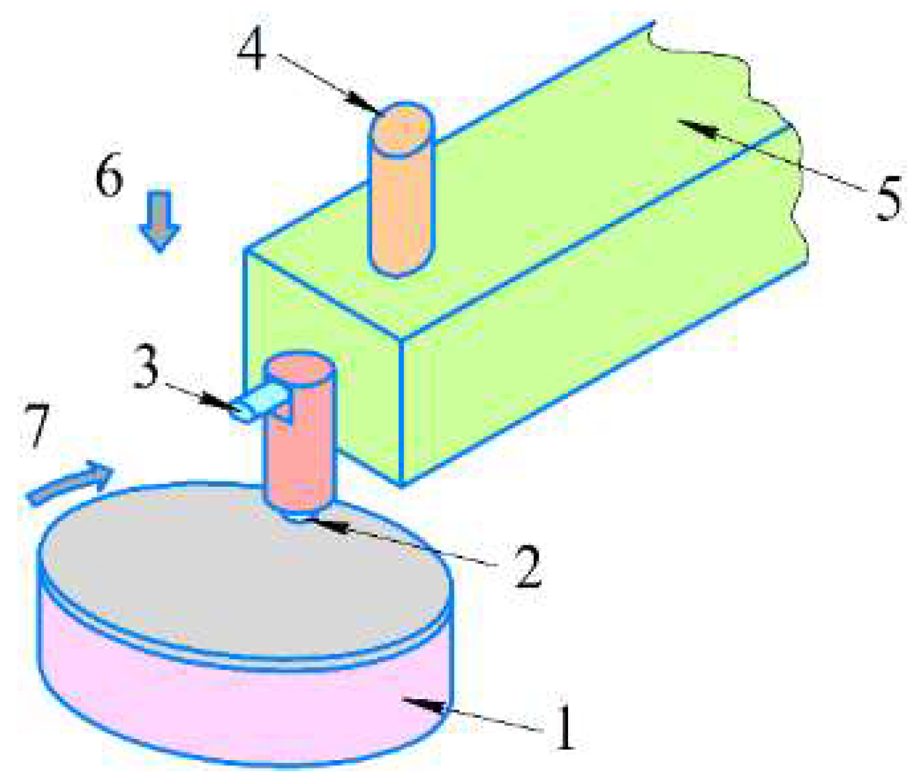
2. Materials and Methods

The single-layer ZrN and CrN as well as multi-layer ZrN/CrN coatings deposited by means of the vacuum-arc method on WC-8 wt.% Co substrates have been studied.
The multi-layer coatings had different layer thicknesses and nanohardness numbers (Table 1), resulting from varying the deposition regimes. When varying the deposition regimes, the sample holder’s rotation frequency was changed. The coating deposited at rotation frequency of 0.5 rpm is designated in this work as ZrCrN(0.5) so that other ones obtained successively at 3.5 rpm, 5 rpm and 8 rpm will be ZrCrN(3.5), ZrCrN(5) and ZrCrN(8), respectively. The more detailed description of the deposition technique and coating characteristics was given elsewhere [29,30].
Sliding wear testing was carried out using a ball-on-disk scheme with AISI52100 ∅6 mm steel ball rubbed against the coated disk surface (Figure 1). A tribometer (TRIBOtechnic, Clichy, France) was used for testing using the test parameters preset for simulating the different sliding wear conditions of the coatings. In particular, the normal load values, such as 1 and 6N, were chosen based on the preliminarily obtained results when the 1N load provided almost wearless sliding without any observable damage to all the coatings, while the 6N load corresponded to sliding with some degree of wear that varied with the type of coating. The results of sliding tests with the use of some intermediate load values were not included in this work since they essentially repeated the results and conclusions obtained in the course of this work. The sliding speed was 0.1 m/s.
An EYa-2 setup (Togliatti State University, Togliatti, Russia) attached with a 30–1000 kHz bandpass 8 mm diameter sensor was used to receive and analyze the acoustic emission signals. Parasite signals generated by the mechanical system have been filtered out using a 50 kHz high pass LC-filter. The fast Fourier transformation was used for determining the AE signal amplitude (energy) and frequency (median frequency) characteristics.
The vibration acceleration signals were registered using an IM Industrial accelerometer and USB data logger NI-9234 (National Instruments, Austin, TX, USA) at sampling rate 25.6 kHz. The running root mean square (runRMS) of acceleration was calculated for the 1 s signal acquisition periods. These parameters were used in this paper to characterize the friction-induced vibration accelerations.
Wear of coatings was quantized by measuring the wear track cross-section profile areas on disk surface using a laser scanning confocal microscope Olympus Lext 4100 (Olympus, Tokyo, Japan). Wear volume was calculated from corresponding measurements by means of Olympus optical microscope using the following formula:
V = π × h2 (R − h/3)
where h is the ball’s segment height (mm); R is the ball’s segment radius (mm).
The worn surfaces of coatings were characterized using an SEM instrument Apreo 2S (Thermo Fisher Scientific, Waltham, MA, USA) attached with an EDS add-on.
The synchrotron X-ray Source VEPP-3 (BINP SB RAS, Novosibirsk, Russia) with wavelength 1.79 Å XRD was used for detecting phases in the subsurface of the worn samples. Phase analysis was performed using Match! 3 software (version 3.1, Crystal impact, Kreuzherrenstraße, Germany) and Crystal open database (COD).

3. Results

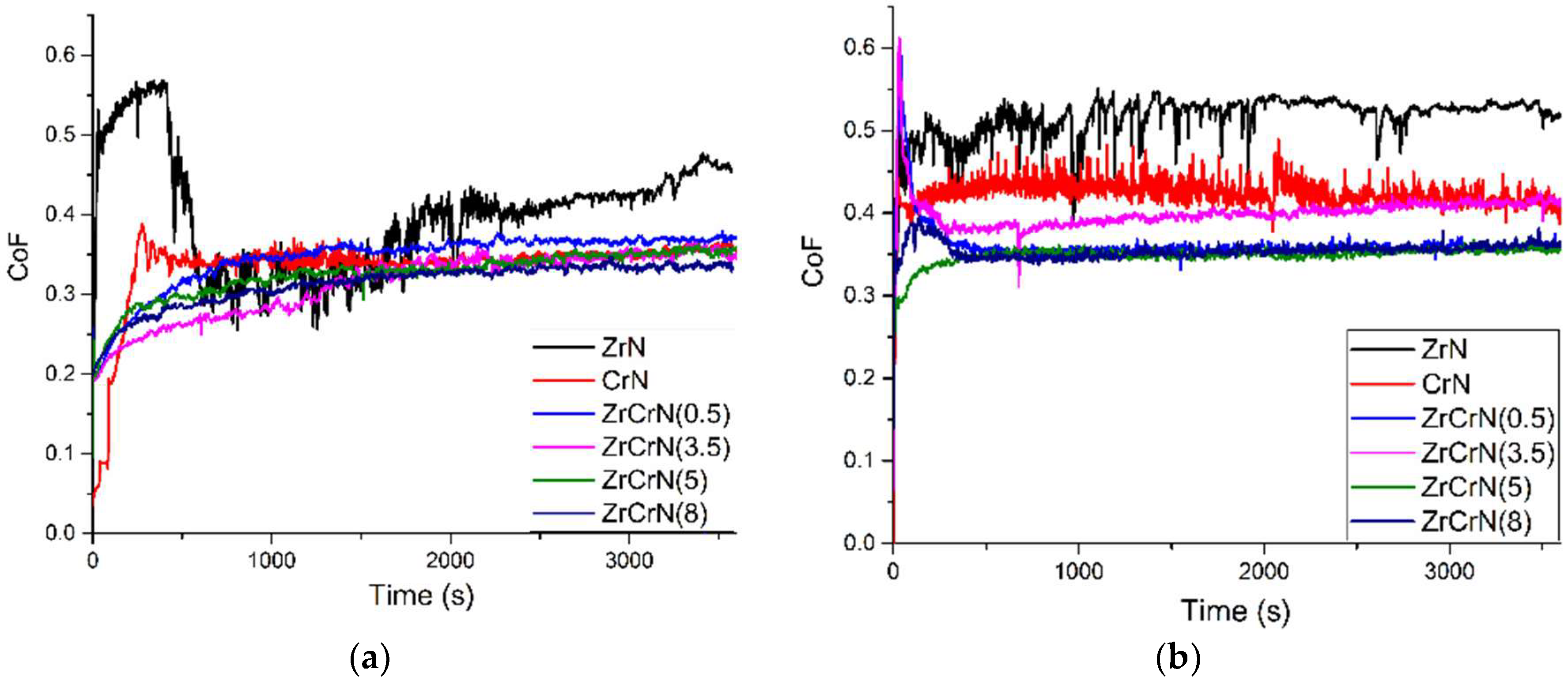
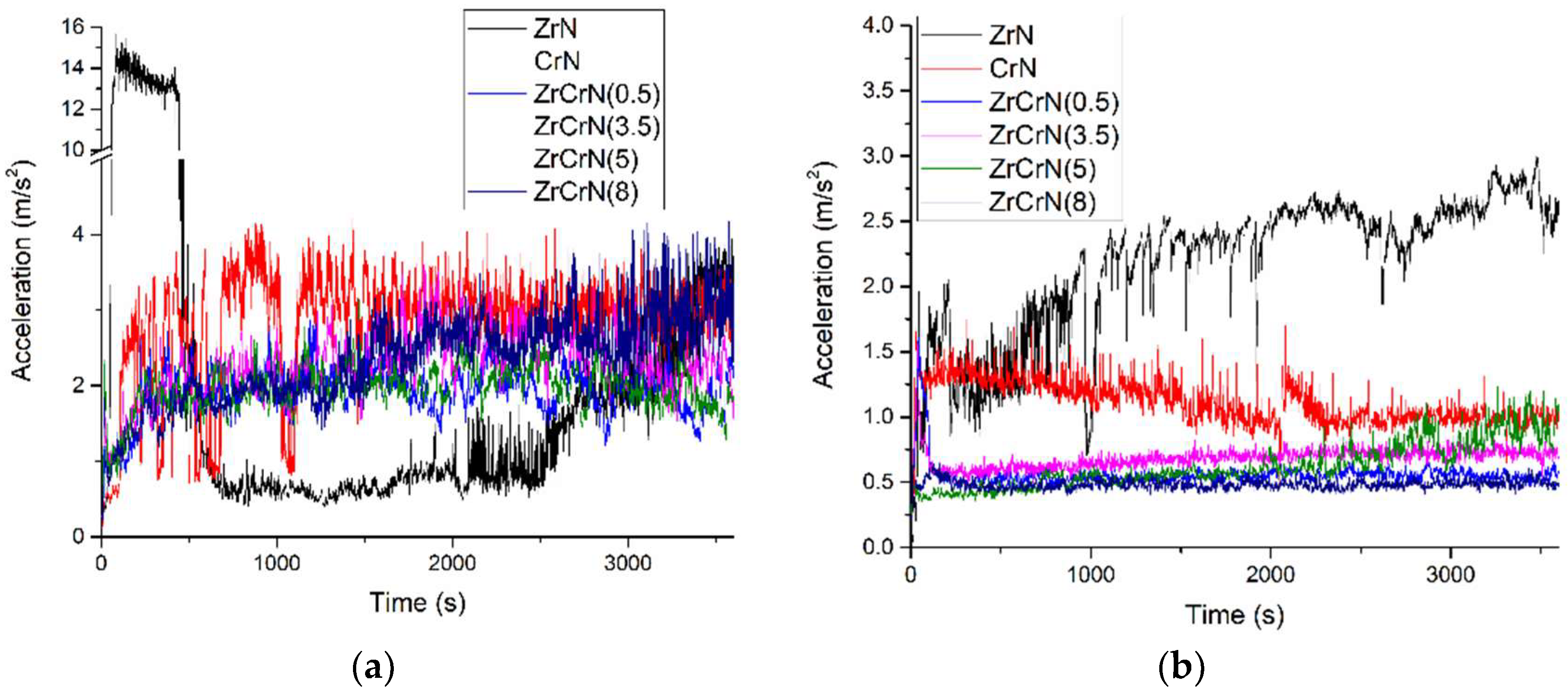
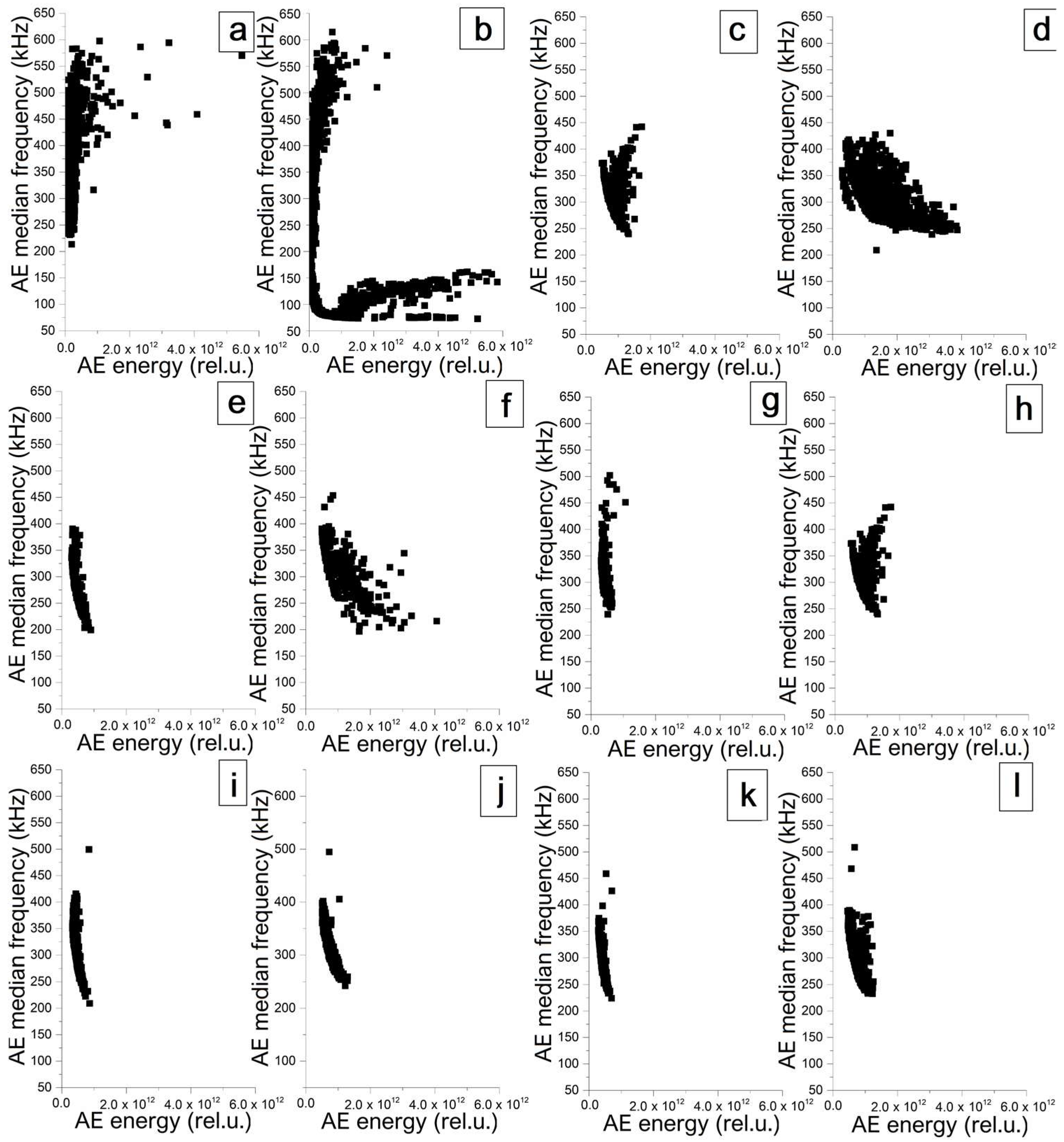
3.1. Coefficient of Friction, Vibration and Acoustic Emission Characterization

Sliding at the normal load of 1N on samples coated with single-layer CrN and multi-layers of (ZrCrN(0.5)-ZrCrN(8)) is characterized by the presence of the running-in stage, during which the friction coefficient gradually increased (Figure 2a). The running-in stage duration was about ~250 s for the CrN-coated sample and 600 s for the multi-layer-coated samples. The next stage was relatively steady friction with the CoF value maintained in the range 0.31–0.34.
When a ZrN-coated sample was tested, the friction coefficient changed as follows. First, there was a rapid increase to ~0.57, followed by a sharp decrease to ~0.31, after which a small plateau was observed, with the CoF dynamically changing within the 0.26–0.36 range during the time period of 1600 s. The last stage was increasing the CoF from 0.32 to 0.46. The average CoF value for this sample was 0.4.
According to the data obtained, the CoF of the multi-layer coatings decreased by 0.03–0.09 as compared with those of ZrN and CrN coatings. Increasing the normal load to 6N led to significant changes in friction dynamics (Figure 2b). The running-in stage of these samples took ~250 s, while the CoF values varied with the type of coating. During sliding on ZrCrN(0.5) and ZrCrN(3.5) multi-layer coatings, the CoF reached ~0.6 value from the very beginning of the test and then decreased exponentially to 0.35 and 0.38, respectively. For the rest of the samples, running-in is accompanied by a gradual increase in CoF. After the running in, the sliding of samples with ZrN and CrN coatings occurred, with significant CoF fluctuations within 0.39–0.55 and 0.38–0.48 ranges, respectively. However, the trend remained constant and CoF amounted to 0.51 and 0.42 for samples coated with ZrN and CrN, respectively. Sliding on samples with multi-layer coatings was not accompanied by any significant CoF oscillations. The average CoF values are 0.34, 0.35, 0.36 and 0.4 for the ZrCrN(5), ZrCrN(8), ZrCrN(0.5) and ZrCrN(3.5) samples, respectively. According to the data obtained, the CoF decreased by 0.02–0.16 as compared with those of samples with ZrN and CrN coatings.
During sliding, friction force oscillations occurred that were recorded using an accelerometer. From the beginning of the sliding at 1N, the vibration acceleration signal amplitude increased (Figure 3a) for samples coated with CrN as well as for those with (ZrCrN(0.5)-ZrCrN(8)) multi-layer coatings. Then, the vibrations acquired a quasi-constant behavior but in the amplitude range as high as 1.5–4 m/s2. For a sample coated with ZrN, the vibration acceleration amplitude reached ~14.5 m/s2 level from the very beginning of the test but then sharply decreased to 0.53 and, after 2000 s, gradually increased again until the end of the test. The average values of vibration accelerations are (m/s2) 2.65, 2.83, 1.88, 2.26, 1.86 and 2.32 for samples coated with ZrN, CrN, ZrCrN(0.5), ZrCrN(3.5), ZrCrN(5) and ZrCrN(8), respectively.
The increase in the normal load to 6N in sliding on samples coated with CrN and (ZrCrN(0.5)-ZrCrN(8)) multi-layers led to a factor of 2.5–4.9 decrease in the vibration acceleration amplitude (Figure 3b) as compared with the those of tested at 1N load. In contrast to the multi-layer samples, sliding on the sample coated with ZrN showed a clear tendency for increasing the vibration acceleration amplitude as the friction process developed. It can be seen from the obtained data that in the main part of the tests (excluding the first 500 s of the running-in stage) vibration acceleration amplitudes obtained from this sample in sliding at 6N (Figure 3b) were higher than those from sliding at the 1N (Figure 3a). The average values of vibration accelerations were (m/s2) 2.17, 1.11, 0.56, 0.67, 0.61 and 0.41 for samples coated with ZrN, CrN, ZrCrN(0.5), ZrCrN(3.5), ZrCrN(5) and ZrCrN(8), respectively.
It is worth noting here that, for qualitative comparison, there is consistency in the nature of the change in the magnitude of vibration accelerations (Figure 2) and CoF (Figure 3) for the samples under consideration at both used loads of 1N and 6N.
Below are the results of estimating the AE signal parameters obtained during sliding. The signals were recorded as separate frames with a duration of 21 ms. Then, for each of these signals, the values of the median frequency and energy have been calculated. It can be seen from the experimental data that, in the case of “wearless”sliding at 1N, (Figure 4a,c,e,g,i,k), the AE signals predominantly have frequencies in the range 200 to 625 kHz and low energy (less than 2 × 10¹² rel.u.). When more severe wear begins with the increase in load, then additional high energy signals appear in the lower frequency end (Figure 4b,d,f,h,j,l). This is expressed most intensively in formation of a whole plume of low-frequency (60–175 kHz) signals from sliding on a sample coated with ZrN (Figure 4b). This is also noticeable in sliding on samples coated with both CrN (Figure 4d) and multi-layer-coated ZrCrN(0.5) (Figure 4f). In all these cases, a group of high-frequency signals are retained. It will be shown below that these three samples experienced the most intensive wear. On the contrary, minimal wear was observed on the ZrCrN(3.5), ZrCrN(5) and ZrCrN(8) samples, as could be followed from the AE signal parameters. As can be seen from the data obtained (Figure 4h,j,l), the signals grouped in the regions look like crescents. These signals, in comparison with the signals recorded in the absence of wear (Figure 4g,i,k), have slightly increased energy values and additional signals appear in the high-frequency region.

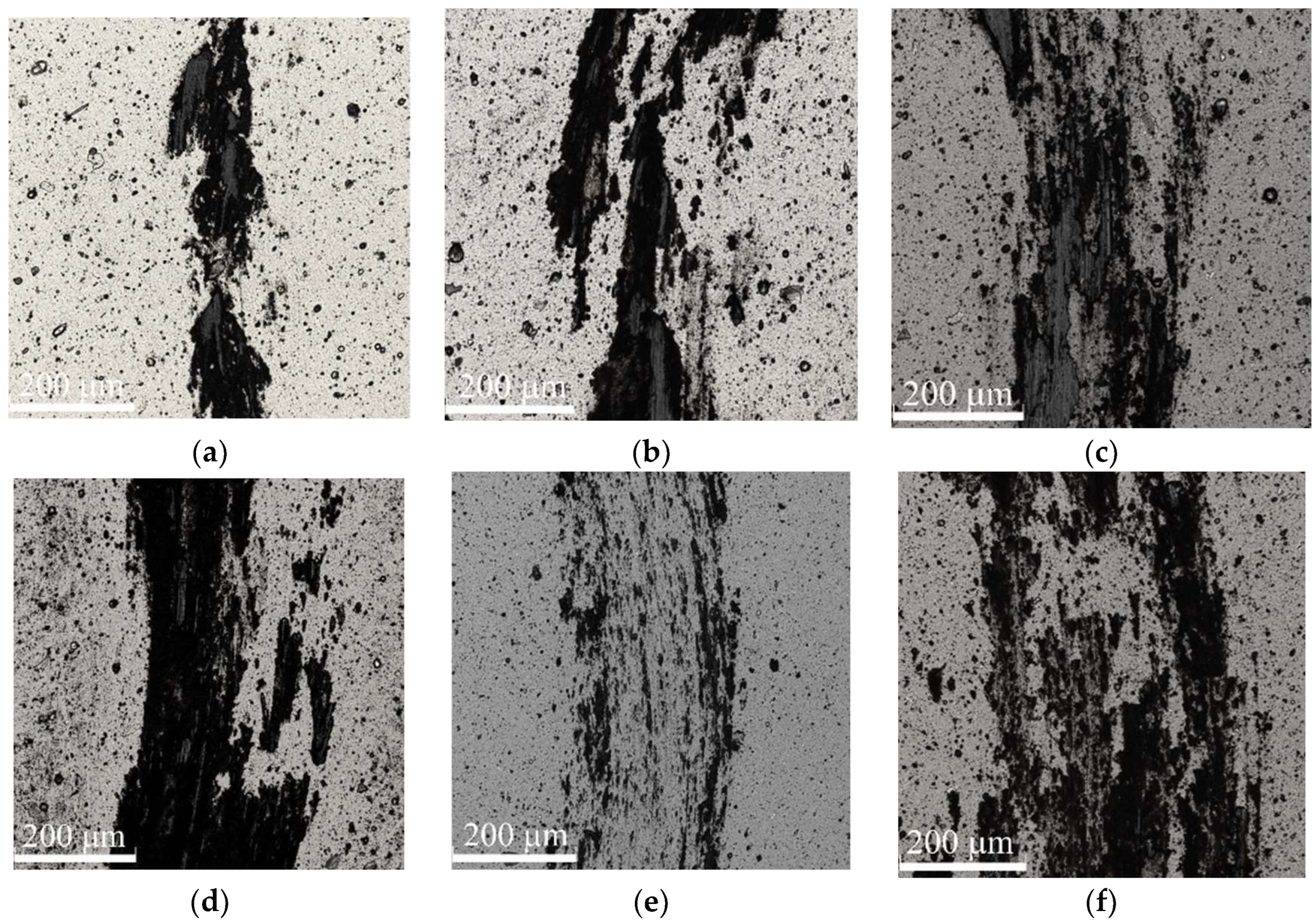
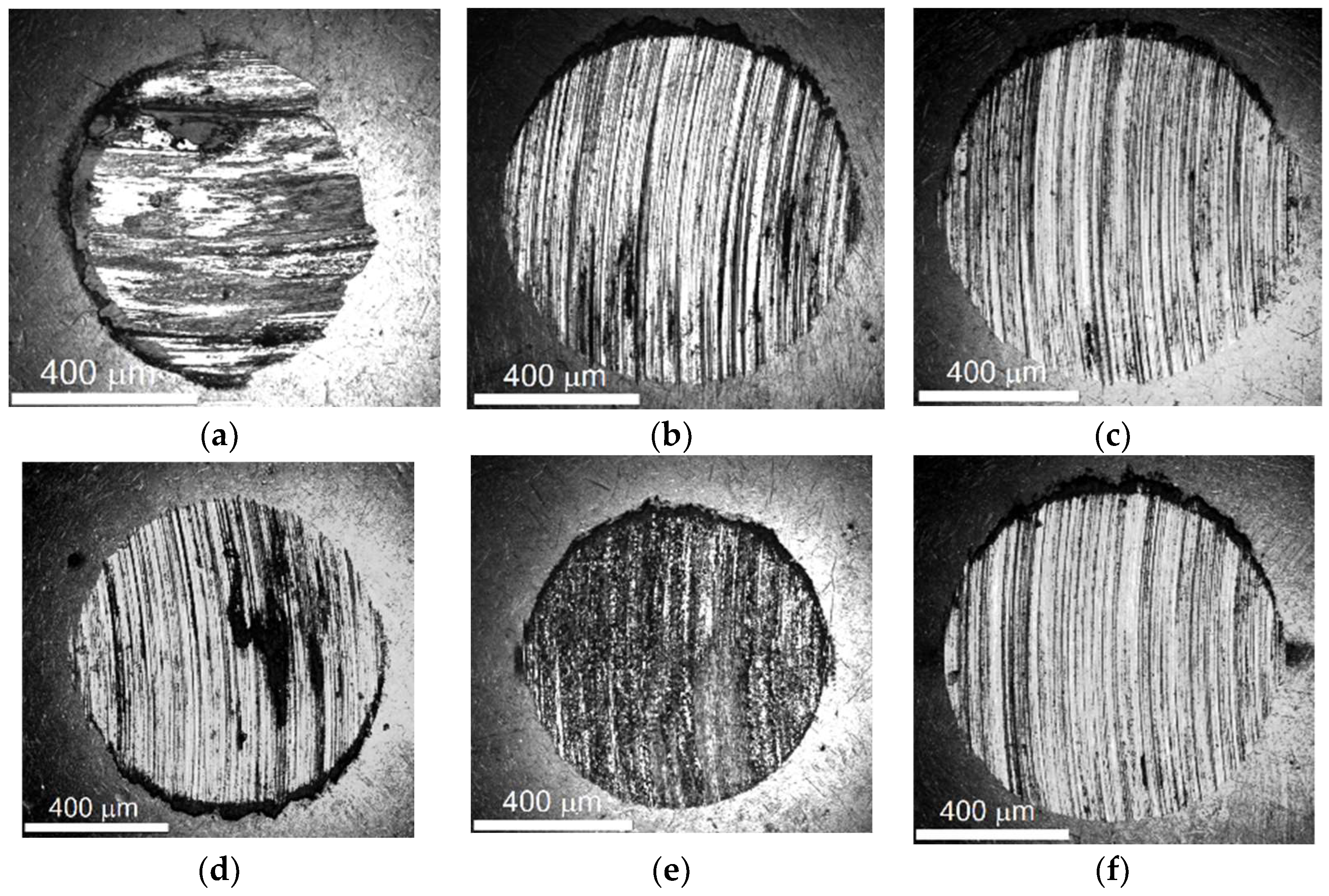
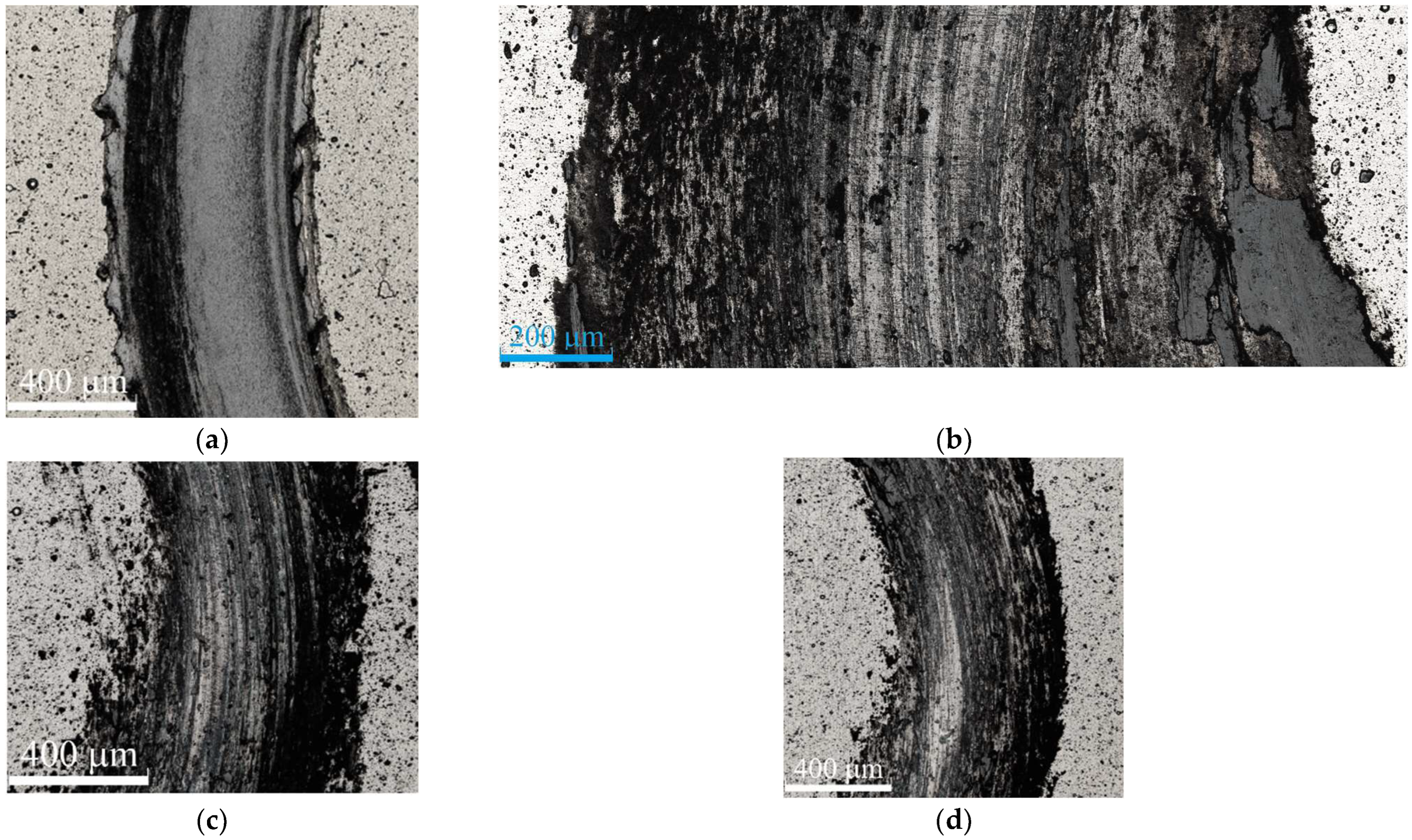
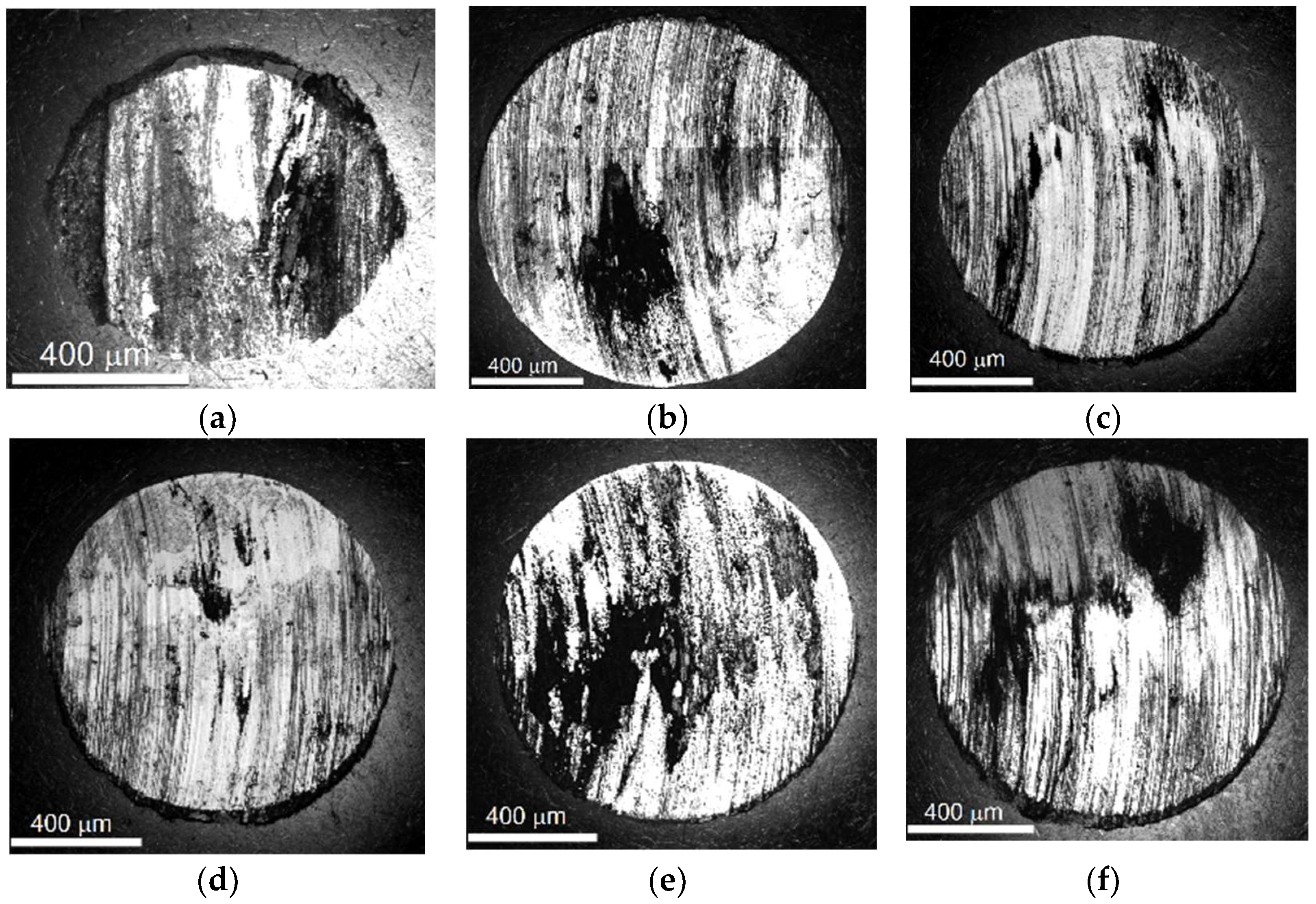
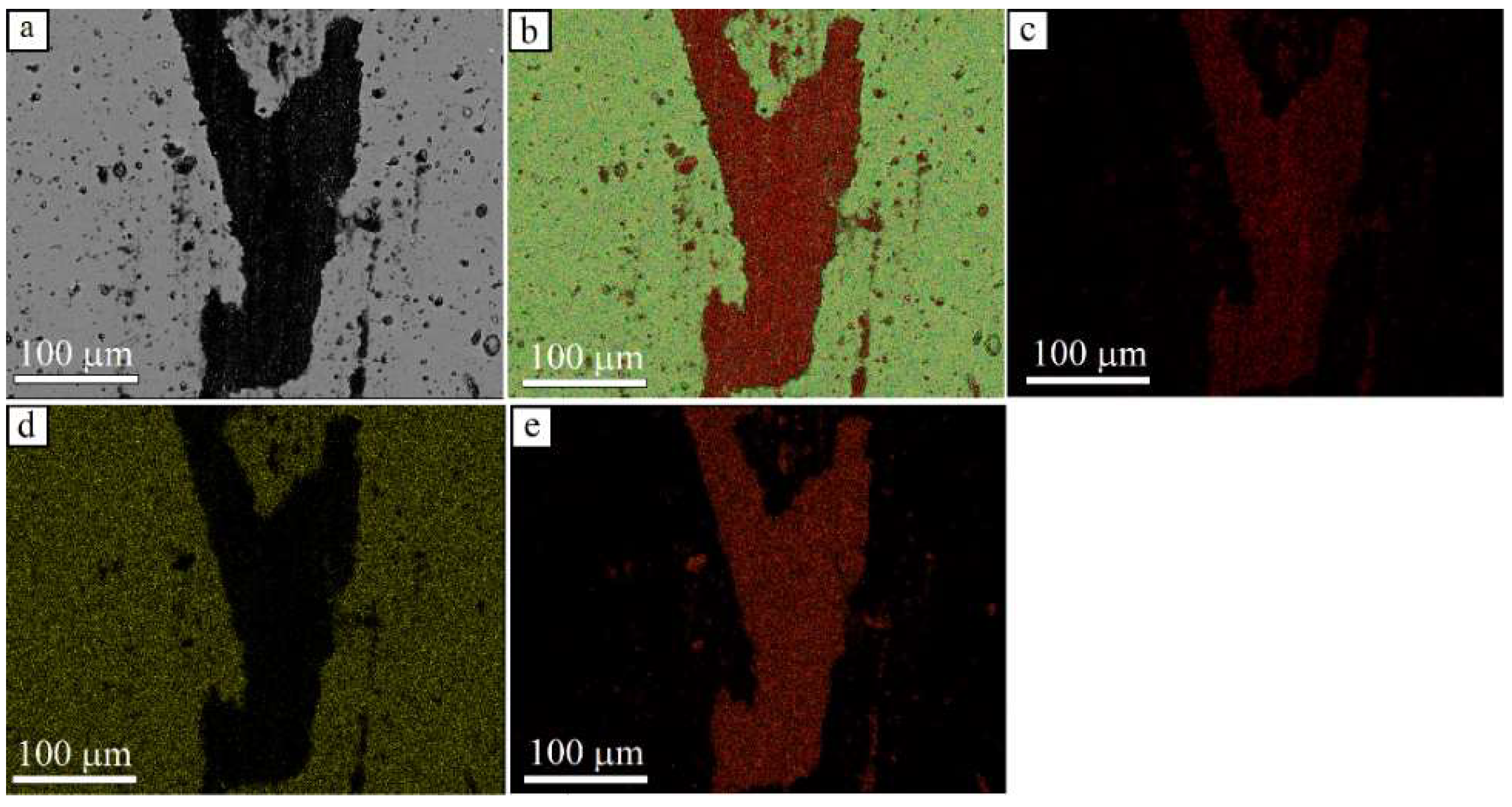
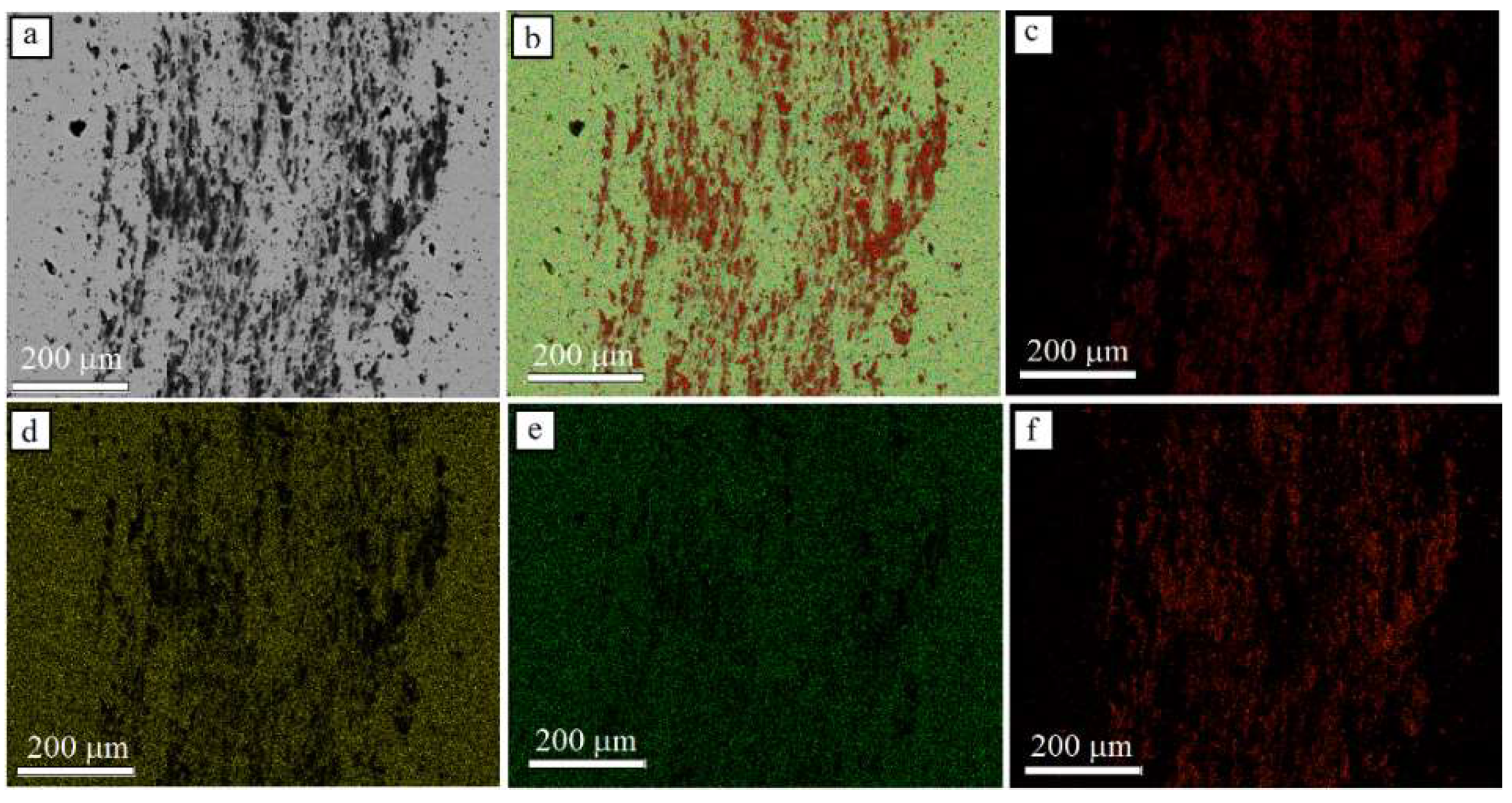
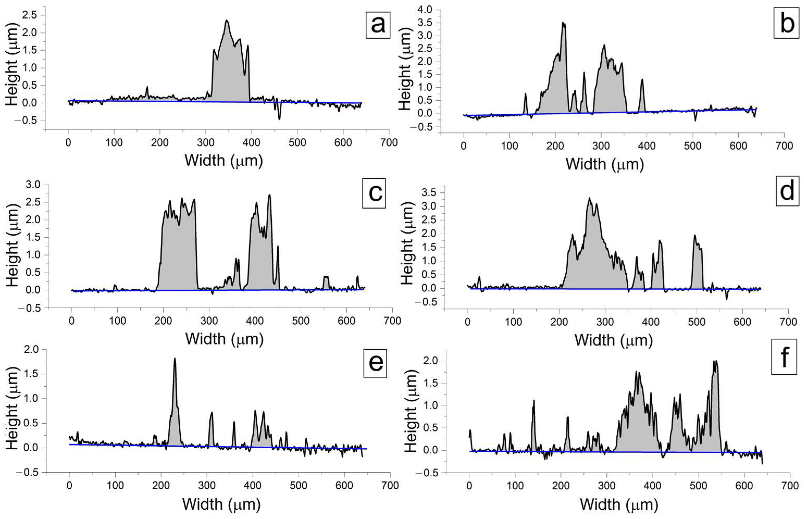
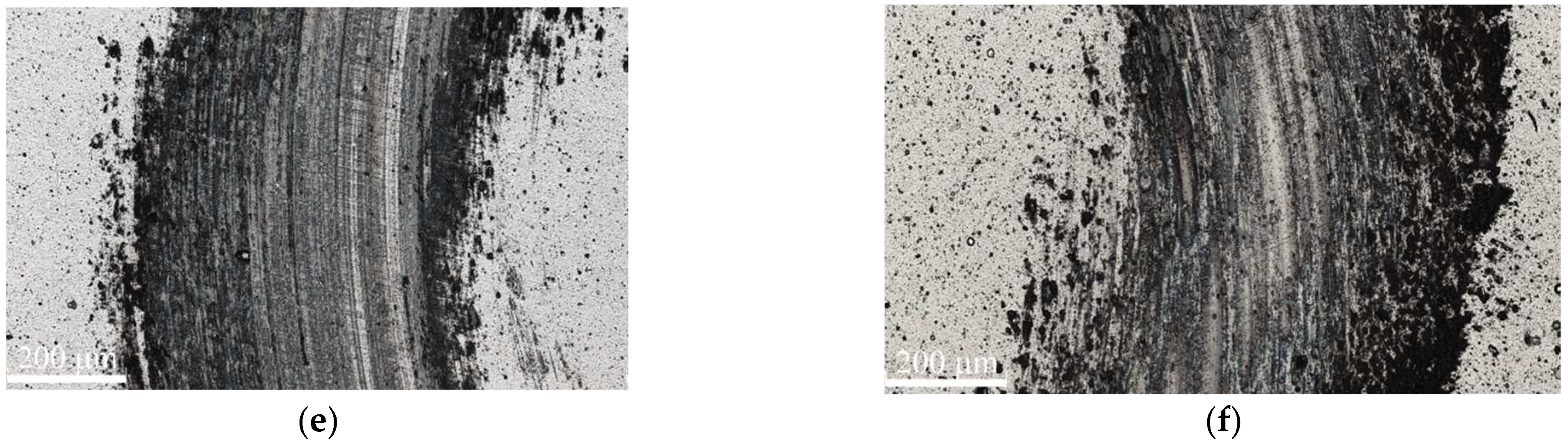
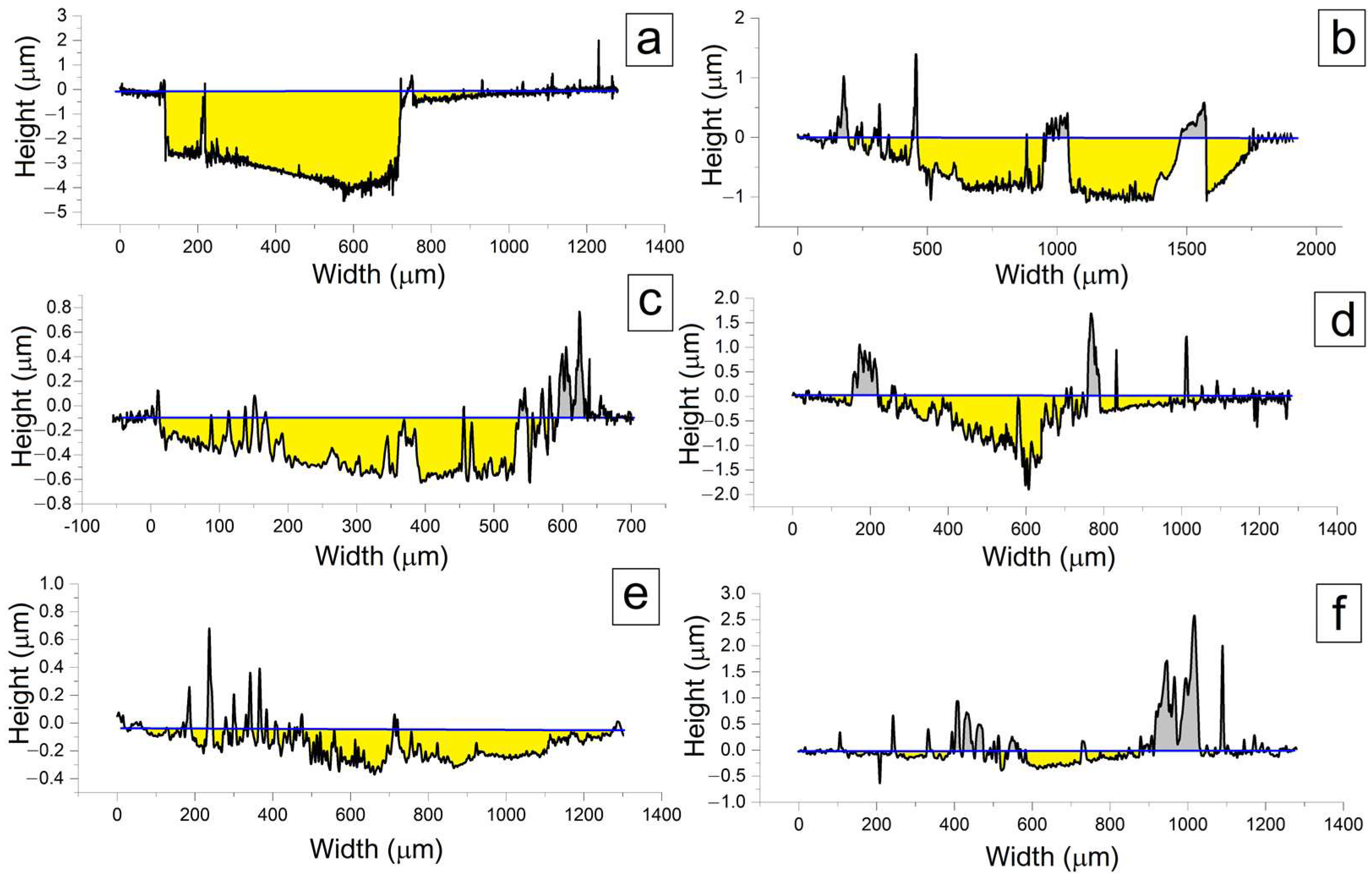
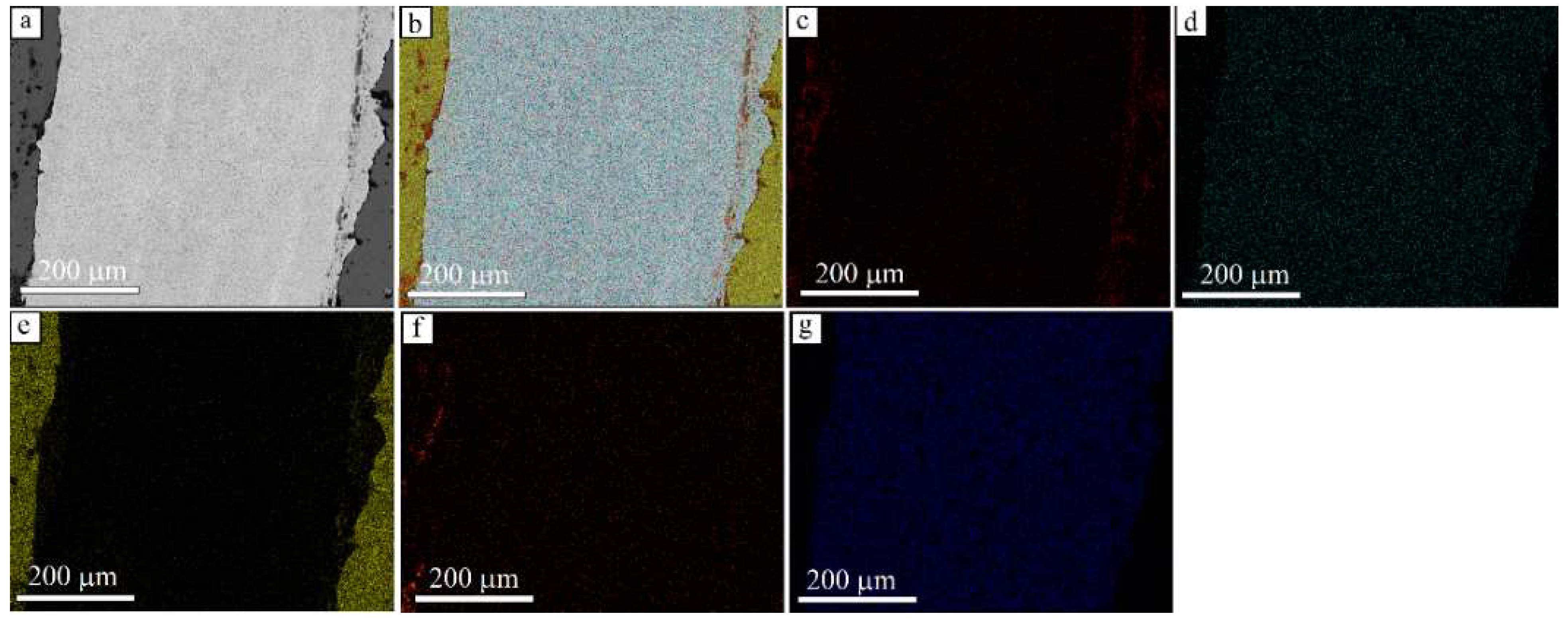
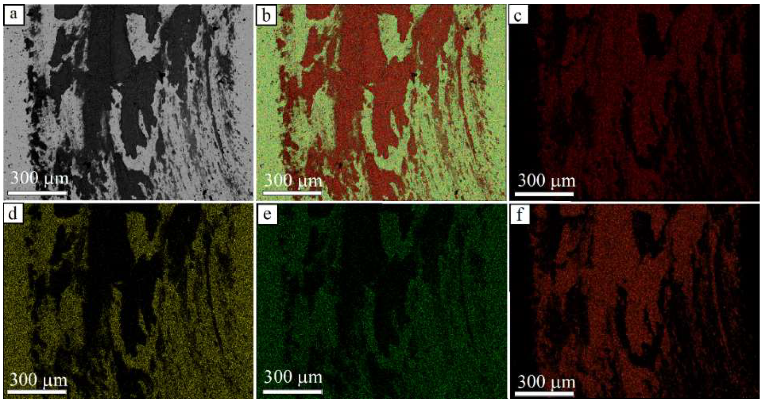
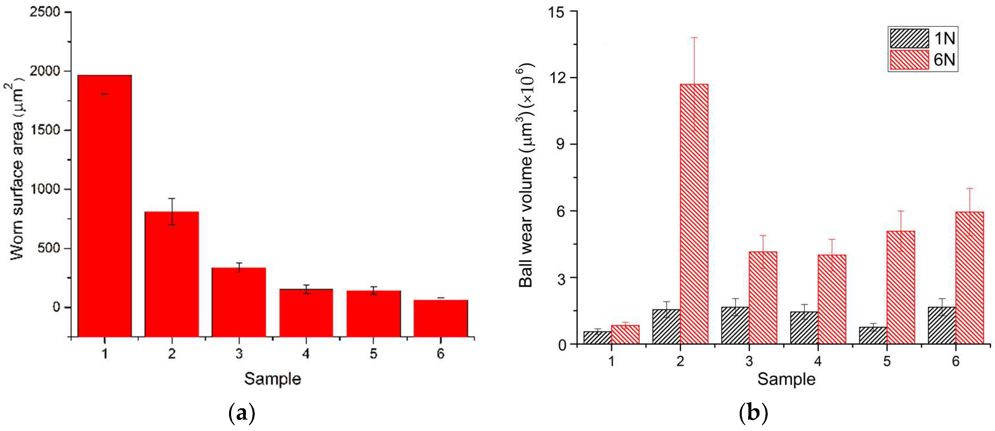
3.2. Worn Surface Characterization

After sliding at 1N, the dark areas elongated with respect to sliding direction were observed on the worn surfaces of all the samples with coatings (Figure 5). Using laser scanning microscopy, it was revealed that, in all cases, the dark areas were formed by oxidized and transferred material of the ball (Figure 6) since no traces of wear or deterioration were found on the worn surface of the coatings. The mean thickness of the transfer layers adhered to the coatings is about 1–4 microns (Figure 6). These transfer layer areas are located as patches on the coating surface, which is most likely due to their low adhesion to the coating material. As a result, these transfer layer patches can be transferred back to the ball, carried away and again adhere to the coating or be removed from it in the form of wear debris.
When analyzing the wear tracks, it becomes obvious that they have different widths. This qualitatively agrees with the change in the diameter of the wear scar on corresponding steel ball surfaces (Figure 7). Wear grooves (scratches) are clearly visible on the worn surface of the steel balls as formed along the sliding direction. In the case of sliding of the ZrN-coated sample, the wear scar on the ball is geometrically uneven and contains traces of material reverse transfer.
After sliding at 6N of normal load, the transfer layer areas become continuous as well as mechanical wear traces appear on the worn surfaces of coatings (Figure 8). The optical micrographs also indicate a noticeable increase in the wear track width as compared to those obtained after sliding at 1N load.
The wear track cross-section profiles were reconstructed (Figure 9), which allowed assessing the degree of wear of the coatings and thus confirming the presence of transfer layer areas. As can be seen from the presented profiles, the wear of coatings varies significantly. Thus, the ZrN coating was completely destructed (Figure 8a and Figure 9a) so that traces of material extrusion became visible on the periphery of the wear track. A narrow black band is clearly visible on the surface of this wear track, which is the result of adhesion of oxidized wear products.
The CrN coating experienced intensive wear, but some of the coating thickness is still retained, which means that it had higher wear resistance as compared to that of the ZrN coating. In this case, the wear track width was the largest, and transfer layer fragments were observed on its surface. This is partly due to the wear of the coating, but, to a greater extent, it is the result of the ball wearing that the wear track width increased as compared to those in other cases. In addition, a large number of wear particles were formed, which were then trapped in the micro-roughness of the wear track and created an oxidized layer on the surface of the coating.
Based on the data obtained, it can be observed that the wear of multi-layer coatings is significantly less than that of both ZrN and CrN coatings. In all cases, the wear track depth did not exceed the thickness of the coatings. The wear tracks were narrower, with fewer transfer layer areas in comparison with those on the worn CrN coating. The surface of the wear tracks looked irregular (Figure 8c–f), as can be observed from Figure 9c–f.
Significant wear was observed on the surface of all the balls (Figure 10) with wear grooves aligned with the direction of sliding. In addition, all the balls showed oxidized areas as well as small patches of transfer layer.
Scanning electron microscopy (SEM) with EDS was used to analyze the transfer layer as well as oxidized areas on the wear track surfaces. Two sets of samples with the most characteristic wear features were used. First, these were samples with a ZrN coating, which showed their sufficient wear-resistance in sliding at 1N load, contained oxides on the worn surface and were severely worn in sliding at 6N.
Second, these were ZrCrN(5) samples that were typical representatives of the multi-layer coatings studied in this work and whose wear resistance depended on the load being either high or sufficient. Figure 11a shows an SEM image from the wear track surface with a characteristic dark spot similar to those observed in Figure 5a and formed after sliding at 1N. The EDS element distribution maps in Figure 11b show the composition difference between the transfer layer and ZrN coating. Upon closer examination, it becomes obvious that this transfer layer is composed of iron oxide since Fe (Figure 11c) and O (Figure 11e) are its main components, whereas Zr (Figure 11d) is detected outside of the spot.
Because of increasing the load to 6N, a distinct wear track was formed on the surface, as demonstrated by the SEM image in Figure 12a. The combined image (Figure 12b) obtained for the sum of chemical elements Zr, Fe, O, W and Co shows that the coating was completely removed from the track surface while retained on its edges (Figure 12e). Oxidation is partially present precisely on the retained part of the coating (Figure 12c), and only barely noticeable presence of O is observed on the surface of the WC-Co substrate. In addition, there are only traces of Fe remaining on the retained part of the coating (Figure 12f), which coincide in location with the area containing O and thus indicate the presence of iron oxides.
As a rule, a patchy layer of oxidized transfer material is formed on the worn surfaces of the samples of the multi-layer coatings rubbed at 1N and studied in this work (Figure 5c–f). The SEM image of a typical sample shows that its worn surface is covered with fragments of iron oxides. This is confirmed by the results of EDS analysis. Judging by the obtained data, O (Figure 13c) and Fe (Figure 13a) are detected exactly within the dark spots (Figure 13a), while Zr (Figure 13d) and Cr (Figure 13e) are located on the friction track surface, thus confirming the retained integrity of the coating.
As the load increased to 6N, the layer of oxidized material on the surface of the multi-layer-coated sample began to occupy noticeably larger areas on the wear track (Figure 14a) as compared to those resulting from sliding at 1N. As discussed above, both O (Figure 14c) and Fe (Figure 14f) are concentrated in the dark areas on the SEM image (Figure 14a). The rest of the surface is characterized by the presence of only Zr (Figure 14d) and Cr (Figure 14e), which confirms retention despite some wear (Figure 8e and Figure 9e) integrity of the coating.
To identify the oxides formed on the surface of the samples with coatings after testing, X-ray diffraction analysis was carried out (Figure 15). Samples obtained after sliding at 6N will be further considered here as typical examples. When reconstructing the diffractograms, the logarithmic scale of the reflection intensity axis was used for better identification of the phases. All the diffraction patterns clearly show WC reflections, which may originate from the WC-Co substrate. When examining a sample coated with ZrN, Co reflections were also detected due to the fact that part of the ZrN coating was removed. In other cases, the Co reflections have not been observed unless there was full deterioration of the coating and exposure of the substrate. The reflections of both ZrN and CrN are well distinguishable when obtained from the single-layer coatings (Figure 15a,b). Based on the analysis of other reflections observed in all cases, the sliding-formed oxides can be identified as Fe3O4. No other phases or oxides were found.

4. Discussion

To analyze the results, the wear characteristics were obtained and plotted in the form of graphs in Figure 16. These wear characteristics were represented by the wear track cross-section profile areas on the coatings (Figure 16a) and volume losses on steel balls (Figure 16b).
The results obtained are unexpected ones for a number of reasons. First, even mild wear of the coatings was not achieved during sliding at 1N due to the insufficient intensity of the mechanical action. This was one of the conditions for recording the AE and vibration signals and then assessing the applicability of the AE-base criteria of wear previously established for monitoring the processes of sliding and metal cutting [31,32,33,34,35,36].
Second, as found earlier [37], the nanohardness of the coatings is 21.6 GPa for the CrN coating, 29.8 GPa for the ZrN coating, 34 GPa for the ZrCrN(0.5) coating, 37.5 GPa for the ZrCrN(3.5) coating, 39.3 GPa for the ZrCrN(5) and 45 GPa for the ZrCrN(8) coating. The nanohardness of AISI 52100 steel is about ~8 GPa, which is consistent with the data of [38]. Consequently, the wear of steel balls may be higher because of their lower mechanical properties. As a result of sliding, the steel ball wear particles are formed and transferred to the coating being oxidized in the process, thus creating a thin layer of oxides on the surface of the wear tracks. This layer may reduce the intensity of the mechanical impact on the rubbing surfaces.
Third, with the increase in the normal load to 6N, wear is observed not only on steel balls but also on the coated samples. As a result, there is an opportunity to evaluate the wear resistance of the studied multi-layer coatings and simultaneously record the AE and vibration signals under conditions of complete wear of the ZrN, CrN and ZrN/CrN multi-layer coatings. This may contribute to development of methods for monitoring the process of sliding wear using the AE and vibration signals. The wear of multi-layer coatings turned out to be significantly less than that of the single-layer CrN and ZrN coatings. This is determined by their higher mechanical properties, namely nanohardness, which is consistent with the previously published data [39]. Their high nanohardness is due to the multi-layer structure, and the differences are determined by the thickness of the layers, which was previously established [37]. Similar observations were demonstrated in the form of an increase in the wear resistance of nitride coatings containing chromium and zirconium, which was due to their solid solution hardening and an increase in internal stresses [40,41,42,43]. The destruction of the ZrN coating is apparently caused by its insufficiently good adhesion to the substrate material, as a result of which it is delaminated and crushed with an increase in the load. This was also indirectly confirmed by the fact that even fragmentary remnants of the coating were not preserved on the friction tracks.
Summarizing the data on the CoF value, vibration and AE signal parameters, the graphs were reconstructed that showed the average values of these characteristics during sliding at 1N (Figure 17a) and 6N (Figure 17b). The higher value of CoF in sliding at 6N is due to a change in the tribocontact conditions. At a load of 1N, a layer of iron oxides is observed on the surface of the samples, which contributes to the decrease in CoF. During friction with a load of 6N, more intensive wear of the coatings is observed; therefore, the oxide layer is less stable and might be carried away so that contacting occurs on the denuded coating surfaces. The third body (transfer layer) is removed, and, as a result, adhesion between the surfaces increases, thus causing the increase in CoF. A similar analogy can be followed when analyzing the adhesion during sliding between the steel surfaces [44], as well as in the presence friction modificators, which serve as a third body [45].
It is also worth noting that the increase in vibration acceleration amplitude in the normal direction (the direction used for measuring in this work as shown on the test scheme) coincides with the friction reduction, which is also consistent with the results reported [23]. Vibration accelerations, in contrast to CoF, decrease with increasing the load from 1N to 6N. The large value of vibration accelerations is due to formation of rough transfer layer patches with thicknesses in the order of 1–4 μm and consisting of oxidized wear particles on the surface of the coatings (Figure 5 and Figure 6). This layer does not have good adhesion to the coating material and, therefore, breaks up periodically and is removed from the area where friction tracks are formed. As a result, there is significant roughness on the worn surface, and the destroyed oxide layer is transferred to and back between the rubbing surfaces.
All this leads to generation of periodic oscillations transmitted to the ball holder and then recorded by the accelerometer in the form of vibration accelerations. With the increase in the load, the adhering transfer layer material is usually observed on the periphery of the wear track. Less transfer layer is observed on the main part of the tracks since it is concentrated mostly in micro-roughness formed during the wear process (Figure 8 and Figure 9). As a result, friction occurs with fewer oscillations. Similar conclusions were reached by the authors [46], who, using in situ experiments, showed that friction force and oscillations of the tribosystem change during formation and destruction of the third body (oxide layer).
It was also shown [47] that, during friction at low CoF, the dynamic oscillations of the tribosystem increase due to the non-uniformity of the friction process, which is consistent with the results obtained in this work. The AE energy in high load sliding (6N) is generally higher than that in low load friction (1N). It is also noticeable that, during friction of the CrN sample, the AE energy decreases more significantly than in other cases. Its value becomes lower than that recorded during sliding of this sample at 1N. This may be due to the most intensive wear of the steel ball during sliding of this coating at 6N (Figure 16b). The result is adhesive seizing and formation of a large number of wear particles that can adhere to the surface of the wear track (Figure 8b), thus forming mechanical mixed layers (MML).
Consequently, the AE signals recorded during the sliding are formed due to the wear of the steel ball as well as the formation and destruction of MML and wear of the coating. The obtained data indicate that AE signal energy shows a tendency to decrease with wear of multi-layer coatings during friction at 6N, whereas the AE energy is approximately at the same level for the same samples rubbed without pronounced wear. Therefore, AE energy value can be considered as a wear intensity criterion. An increase in the intensity of AE signals, and, consequently, their energy, in the process of adhesive wear of a silver coating was also noted elsewhere [48], which indicates the reliability of our conclusions.
The ZrN coating was fully destructed in sliding at 6N and the recorded AE parameters (energy and median frequency) in this case differ significantly from the others considered. The high energy of the AE signal can be associated with the process of destruction of the coating, in the course of which cracks are formed that generate the high energy signals. It was also previously established [32] that, when brittle materials fail by cracking, the median frequency decreases significantly as compared to that of more ductile materials. This is consistent with the results of the current observation. During the wear destruction of the ZrN coating in sliding at 6N, the recorded AE signals had a median frequency approximately two times lower than that obtained from sliding of all the other coatings, both at low and high loads. In the case of friction at 6N (with the exception of the ZrN coating), the averaged values of the median AE frequency do not show any significant changes, as determined on other coatings. Moreover, there are no regularities in its change during friction with a small load of 1N. Consequently, this parameter in the current tests turned out to be an ineffective means of monitoring the friction process. If we compare tests with different loads during friction of multi-layer coatings, one can see that the median AE frequency with noticeable wear is somewhat higher than that during friction without any wear. This may be due to more intensive wear of steel balls with the increasing load. Their wear will have a less adhesive nature, which, as shown in [49,50], leads to viscoelastic fracture. In this context, the increase in the median frequency is due to the mechanism of wear of steel balls and is similar in nature to that previously observed in [32].

5. Conclusions

The single-layer ZrN and CrN, as well as multi-layer ZrN/CrN coatings deposited by vacuum arc deposition, were tested under sliding conditions at normal loads of 1N and 6N that served to provide different friction and wear conditions. During the tests, AE and vibration signals were recorded. Based on the obtained experimental results, the following conclusions were drawn:
  • Under conditions of dry sliding friction with a normal load of 6N, the wear of multi-layer ZrN/CrN coatings turned out to be significantly less (by a factor of 2.4–12) than that of monolithic CrN coatings. This is determined by their higher mechanical properties, namely nanohardness.
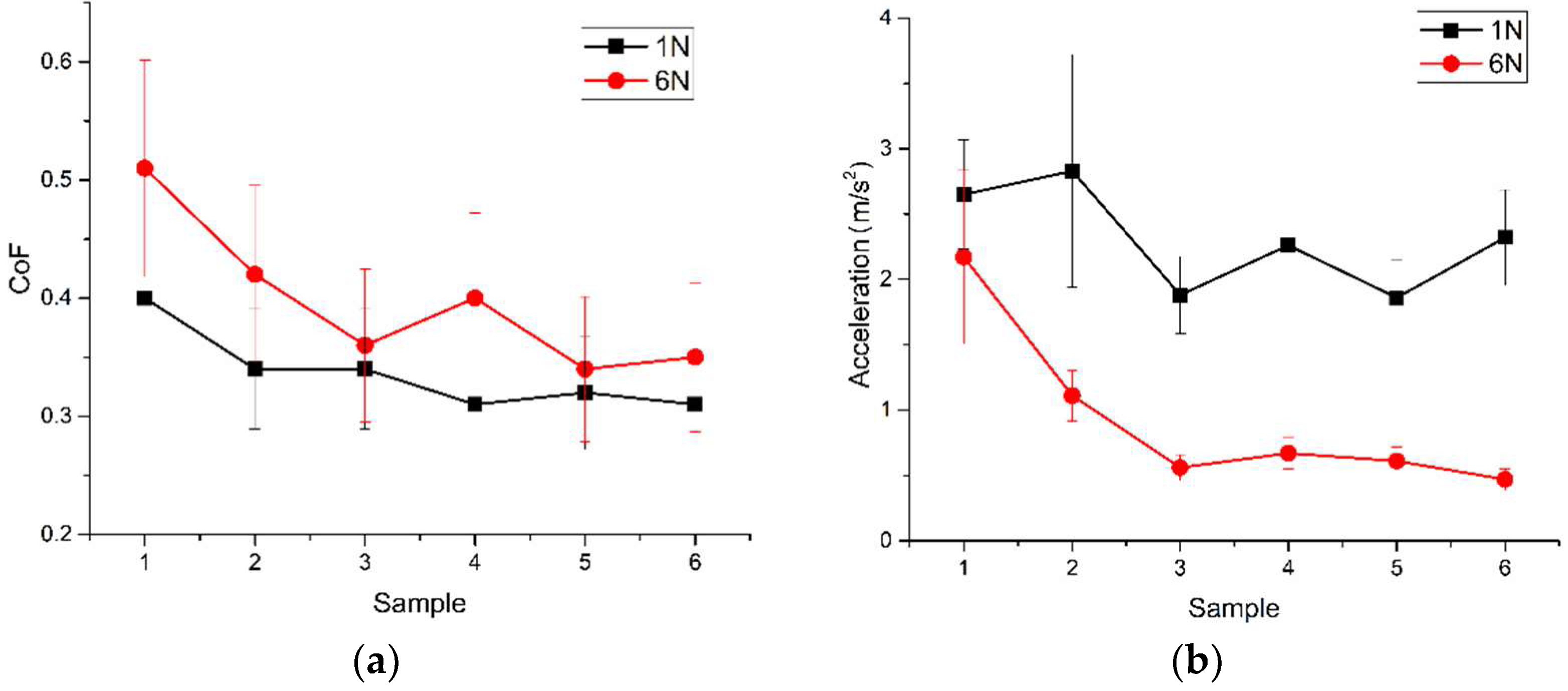
  • The change in the value of CoF during dry sliding friction is due to a change in the conditions of the tribocontact. An increase in load leads to uneven formation of a transfer layer, which is unstable under load and, being destroyed, exposes the surface of the coating, contributing to an increase in the adhesive interaction in the tribocoupling. This, in turn, leads to an increase in the friction force. In the friction of ZrN/CrN multi-layer coatings, CoF is reduced by 5–50% in friction with a normal load of 6N and by 9–29% in friction with a normal load of 1N compared with single-layer coatings of CrN and ZrN.
  • Vibration accelerations (vibrations) decrease by 2.5–4.9 times, while load increases from 1N to 6N. The large value of vibration accelerations is due to the rough worn surface of the wear tracks covered by 1–4 μm thick transfer layers. The counterbody sliding on such a surface is accompanied by oscillations of the tribosystem.
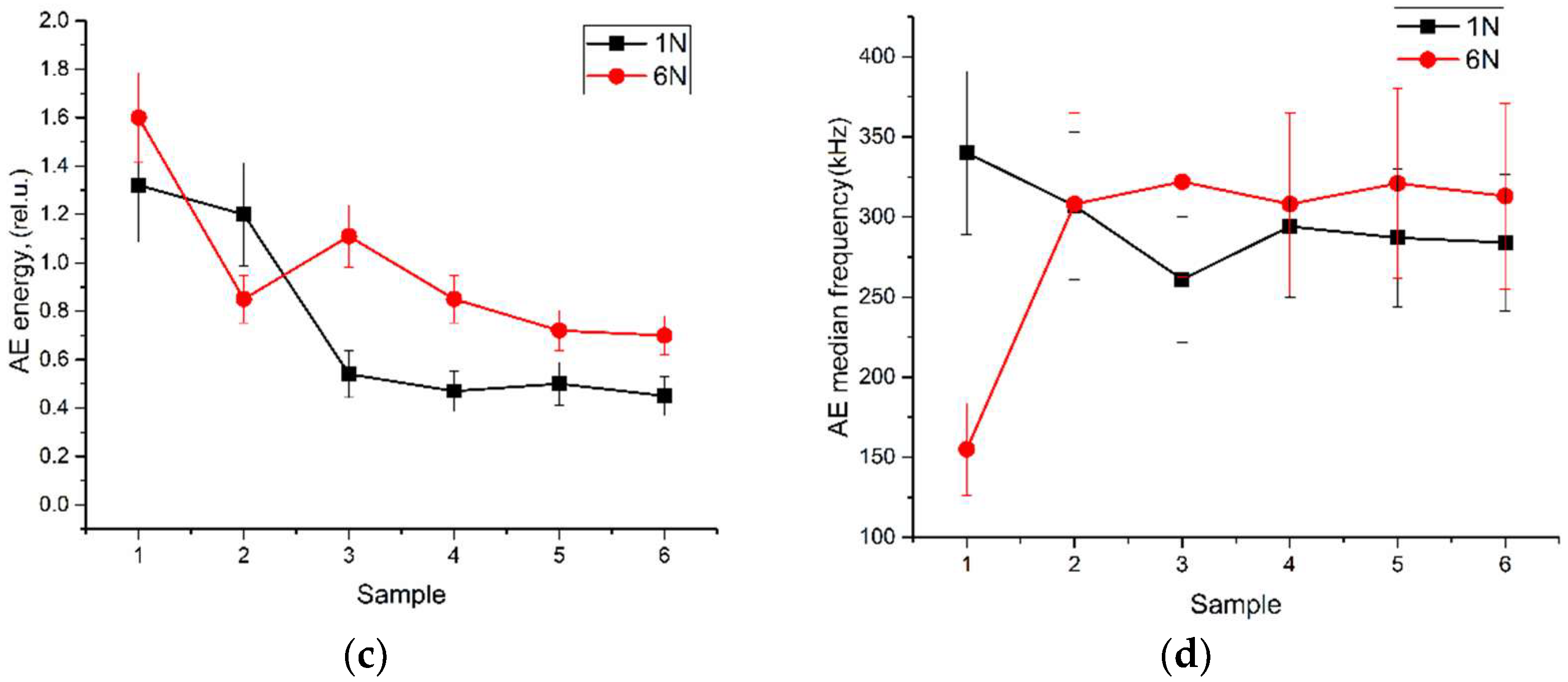
  • The data obtained indicate that the AE energy tends to decrease as the wear of samples with multi-layer coatings decreases during friction with a normal load of 6N. The AE energy is approximately at the same level for the same samples in sliding without pronounced wear. Therefore, if the friction pair similarity condition (multi-layer coating vs. steel ball) is satisfied, the AE energy value can be considered as a wear intensity criterion.
  • During dry sliding on samples with coatings, the averaged values of the median AE frequency do not change significantly. Consequently, this parameter turned out to be an ineffective means of monitoring the friction process. With an increase in the normal load, the median frequency increases, which is due to more intensive wear of the steel balls.

Author Contributions

Conceptualization, writing—original draft preparation, A.F. and O.N.; methodology, writing—review and editing, A.F. and S.T.; validation, A.V. and Y.D.; formal analysis, N.S.; visualization, investigation, E.M. and E.K.; data curation, A.L. and V.D.; supervision, S.T. and V.D. All authors have read and agreed to the published version of the manuscript.

Funding

The work was carried out with the financial support of the Russian Federation, represented by the Ministry of Science and Higher Education (project No. 075-15-2021-1348) within the framework of event No. 1.1.16.

Institutional Review Board Statement

Not applicable.

Informed Consent Statement

Not applicable.

Data Availability Statement

Data will be made available based on request to the authors.

Acknowledgments

SEM investigations have been carried out using the equipment of Share Use Centre “Nanotech” of the ISPMS SB RAS.

Conflicts of Interest

The authors declare no conflict of interest.

References

  1. Stueber, M.; Holleck, H.; Leiste, H.; Seemann, K.; Ulrich, S.; Ziebert, C. Concepts for the Design of Advanced Nanoscale PVD Multilayer Protective Thin Films. J. Alloys Compd. 2009, 483, 321–333. [Google Scholar] [CrossRef]
  2. Khadem, M.; Penkov, O.V.; Yang, H.-K.; Kim, D.-E. Tribology of Multilayer Coatings for Wear Reduction: A Review. Friction 2017, 5, 248–262. [Google Scholar] [CrossRef] [Green Version]
  3. Liu, Y.; Yu, S.; Shi, Q.; Ge, X.; Wang, W. Multilayer Coatings for Tribology: A Mini Review. Nanomaterials 2022, 12, 1388. [Google Scholar] [CrossRef] [PubMed]
  4. Zhang, S.; Wang, J.; Wu, R.; Liu, L.; Pan, B.; Liu, C. Structural and Corrosion Resistance Properties of Sputtered Zirconium Nitride Thin Films as Electrode Material for Supercapacitor. J. Alloys Compd. 2022, 900, 163506. [Google Scholar] [CrossRef]
  5. Guan, X.; Zhao, M.; Shi, H.; Wang, Y.; Wang, Z.; Cheng, Y.; Liu, M. CrZrN/ZrN Multilayer Coatings on 316L Stainless Steel towards Anticorrosion Application. Thin Solid Films 2022, 755, 139330. [Google Scholar] [CrossRef]
  6. Uchida, M.; Nihira, N.; Mitsuo, A.; Toyoda, K.; Kubota, K.; Aizawa, T. Friction and Wear Properties of CrAlN and CrVN Films Deposited by Cathodic Arc Ion Plating Method. Surf. Coatings Technol. 2004, 177–178, 627–630. [Google Scholar] [CrossRef]
  7. Wan, S.; Wang, H.; Xia, Y.; Tieu, A.K.; Tran, B.H.; Zhu, H.; Zhang, G.; Zhu, Q. Investigating the Corrosion-Fatigue Wear on CrN Coated Piston Rings from Laboratory Wear Tests and Field Trial Studies. Wear 2019, 432–433, 202940. [Google Scholar] [CrossRef]
  8. Ferreira, R.; Carvalho, Ó.; Sobral, L.; Carvalho, S.; Silva, F. Influence of Morphology and Microstructure on the Tribological Behavior of Arc Deposited CrN Coatings for the Automotive Industry. Surf. Coatings Technol. 2020, 397, 126047. [Google Scholar] [CrossRef]
  9. Chowdhury, M.S.I.; Bose, B.; Yamamoto, K.; Shuster, L.S.; Paiva, J.; Fox-Rabinovich, G.S.; Veldhuis, S.C. Wear Performance Investigation of PVD Coated and Uncoated Carbide Tools during High-Speed Machining of TiAl6V4 Aerospace Alloy. Wear 2020, 446–447, 203168. [Google Scholar] [CrossRef]
  10. Krysina, O.V.; Ivanov, Y.F.; Prokopenko, N.A.; Shugurov, V.V.; Petrikova, E.A.; Denisova, Y.A.; Tolkachev, O.S. Influence of Nb Addition on the Structure, Composition and Properties of Single-Layered ZrN-Based Coatings Obtained by Vacuum-Arc Deposition Method. Surf. Coatings Technol. 2020, 387, 125555. [Google Scholar] [CrossRef]
  11. Vasylyev, M.A.; Mordyuk, B.N.; Sidorenko, S.I.; Voloshko, S.M.; Burmak, A.P.; Kruhlov, I.O.; Zakiev, V.I. Characterization of ZrN Coating Low-Temperature Deposited on the Preliminary Ar+ Ions Treated 2024 Al-Alloy. Surf. Coatings Technol. 2019, 361, 413–424. [Google Scholar] [CrossRef]
  12. Jasempoor, F.; Elmkhah, H.; Imantalab, O.; Fattah-alhosseini, A. Improving the Mechanical, Tribological, and Electrochemical Behavior of AISI 304 Stainless Steel by Applying CrN Single Layer and Cr/CrN Multilayer Coatings. Wear 2022, 504–505, 204425. [Google Scholar] [CrossRef]
  13. Guan, X.; Wang, Y.; Xue, Q. Effects of Constituent Layers and Interfaces on the Mechanical and Tribological Properties of Metal (Cr, Zr)/Ceramic (CrN, ZrN) Multilayer Systems. Appl. Surf. Sci. 2020, 502, 144305. [Google Scholar] [CrossRef]
  14. Feng, P.; Borghesani, P.; Smith, W.A.; Randall, R.B.; Peng, Z. A Review on the Relationships Between Acoustic Emission, Friction and Wear in Mechanical Systems. Appl. Mech. Rev. 2020, 72, 020801. [Google Scholar] [CrossRef]
  15. Babici, L.M.; Tudor, A.; Romeu, J. Stick-Slip Phenomena and Acoustic Emission in the Hertzian Linear Contact. Appl. Sci. 2022, 12, 9527. [Google Scholar] [CrossRef]
  16. Varga, M.; Haas, M.; Schneidhofer, C.; Adam, K. Wear Intensity Evaluation in Conveying Systems—An Acoustic Emission and Vibration Measurement Approach. Tribol. Int. 2020, 149, 105549. [Google Scholar] [CrossRef]
  17. Haas, M.; El Syaad, K.; Cihak-Bayr, U.; Pauschitz, A.; Gröschl, M. Examination of Undisturbed Acoustic Emission Generated by Experimentally Modelled Two-Body Abrasive Wear Events. Tribol. Int. 2020, 141, 105912. [Google Scholar] [CrossRef]
  18. Hase, A. Early Detection and Identification of Fatigue Damage in Thrust Ball Bearings by an Acoustic Emission Technique. Lubricants 2020, 8, 37. [Google Scholar] [CrossRef] [Green Version]
  19. Hase, A.; Mishina, H.; Wada, M. Correlation between Features of Acoustic Emission Signals and Mechanical Wear Mechanisms. Wear 2012, 292–293, 144–150. [Google Scholar] [CrossRef]
  20. Xu, C.; Li, B.; Wu, T. Wear Characterization under Sliding–Rolling Contact Using Friction-Induced Vibration Features. Proc. Inst. Mech. Eng. Part J J. Eng. Tribol. 2022, 236, 634–647. [Google Scholar] [CrossRef]
  21. Feng, K.; Smith, W.A.; Borghesani, P.; Randall, R.B.; Peng, Z. Use of Cyclostationary Properties of Vibration Signals to Identify Gear Wear Mechanisms and Track Wear Evolution. Mech. Syst. Signal Process. 2021, 150, 107258. [Google Scholar] [CrossRef]
  22. Feng, K.; Borghesani, P.; Smith, W.A.; Randall, R.B.; Chin, Z.Y.; Ren, J.; Peng, Z. Vibration-Based Updating of Wear Prediction for Spur Gears. Wear 2019, 426–427, 1410–1415. [Google Scholar] [CrossRef]
  23. Popov, M. The Influence of Vibration on Friction: A Contact-Mechanical Perspective. Front. Mech. Eng. 2020, 6, 69. [Google Scholar] [CrossRef]
  24. Brunetti, J.; D’Ambrogio, W.; Fregolent, A. Evaluation of Different Contact Assumptions in the Analysis of Friction-Induced Vibrations Using Dynamic Substructuring. Machines 2022, 10, 384. [Google Scholar] [CrossRef]
  25. Chen, F.; Ouyang, H.; Wang, X. A New Mechanism for Friction-Induced Vibration and Noise. Friction 2022, 11, 302–315. [Google Scholar] [CrossRef]
  26. Tomastik, J.; Ctvrtlik, R.; Drab, M.; Manak, J. On the Importance of Combined Scratch/Acoustic Emission Test Evaluation: SiC and SiCN Thin Films Case Study. Coatings 2018, 8, 196. [Google Scholar] [CrossRef] [Green Version]
  27. Choudhary, R.K.; Mishra, P. Use of Acoustic Emission During Scratch Testing for Understanding Adhesion Behavior of Aluminum Nitride Coatings. J. Mater. Eng. Perform. 2016, 25, 2454–2461. [Google Scholar] [CrossRef]
  28. Zawischa, M.; Bin Mohamad Supian, M.M.A.; Makowski, S.; Schaller, F.; Weihnacht, V. Generalized Approach of Scratch Adhesion Testing and Failure Classification for Hard Coatings Using the Concept of Relative Area of Delamination and Properly Scaled Indenters. Surf. Coatings Technol. 2021, 415, 127118. [Google Scholar] [CrossRef]
  29. Vorontsov, A.; Filippov, A.; Shamarin, N.; Moskvichev, E.; Novitskaya, O.; Knyazhev, E.; Denisova, Y.; Leonov, A.; Denisov, V. Microstructure and Residual Stresses of ZrN/CrN Multilayer Coatings Formed by the Plasma-Assisted Vacuum-Arc Method. Met. Work. Mater. Sci. 2022, 24, 76–89. [Google Scholar] [CrossRef]
  30. Vorontsov, A.; Filippov, A.; Shamarin, N.; Moskvichev, E.; Novitskaya, O.; Knyazhev, E.; Denisova, Y.; Leonov, A.; Denisov, V.; Tarasov, S. High-Temperature Oxidation of CrN/ZrN Multilayer Coatings. Metals 2022, 12, 1746. [Google Scholar] [CrossRef]
  31. Filippov, A.V.; Tarasov, S.Y.; Fortuna, S.V.; Podgornykh, O.A.; Shamarin, N.N.; Rubtsov, V.E. Microstructural, Mechanical and Acoustic Emission-Assisted Wear Characterization of Equal Channel Angular Pressed (ECAP) Low Stacking Fault Energy Brass. Tribol. Int. 2018, 123, 273–285. [Google Scholar] [CrossRef]
  32. Filippov, A.V.; Rubtsov, V.E.; Tarasov, S.Y. Acoustic Emission Study of Surface Deterioration in Tribocontacting. Appl. Acoust. 2017, 117, 106–112. [Google Scholar] [CrossRef]
  33. Savchenko, N.L.; Filippov, A.V.; Tarasov, S.Y.; Dmitriev, A.I.; Shilko, E.V.; Grigoriev, A.S. Acoustic Emission Characterization of Sliding Wear under Condition of Direct and Inverse Transformations in Low-Temperature Degradation Aged Y-TZP and Y-TZP-AL2O3. Friction 2018, 6, 323–340. [Google Scholar] [CrossRef] [Green Version]
  34. Filippov, A.V.; Nikonov, A.Y.; Rubtsov, V.E.; Dmitriev, A.I.; Tarasov, S.Y. Vibration and Acoustic Emission Monitoring the Stability of Peakless Tool Turning: Experiment and Modeling. J. Mater. Process. Technol. 2017, 246, 224–234. [Google Scholar] [CrossRef]
  35. Filippov, A.V.; Rubtsov, V.E.; Tarasov, S.Y.; Podgornykh, O.A.; Shamarin, N.N. Detecting Transition to Chatter Mode in Peakless Tool Turning by Monitoring Vibration and Acoustic Emission Signals. Int. J. Adv. Manuf. Technol. 2018, 95, 157–169. [Google Scholar] [CrossRef]
  36. Filippov, A.V.; Tarasov, S.Y.; Fortuna, S.V.; Podgornykh, O.A.; Shamarin, N.N.; Vorontsov, A.V. Wear, Vibration and Acoustic Emission Characterization of Sliding Friction Processes of Coarse-Grained and Ultrafine-Grained Copper. Wear 2019, 424–425, 78–88. [Google Scholar] [CrossRef]
  37. Filippov, A.; Shamarin, N.; Moskvichev, E.; Novitskaya, O.; Knyazhev, E.; Denisova, Y.; Leonov, A.; Denisov, V. Investigation of the Structural-Phase State and Mechanical Properties of ZrCrN Coatings Obtained by Plasma-Assisted Vacuum Arc Evaporation. Met. Work. Mater. Sci. 2022, 24, 87–102. [Google Scholar] [CrossRef]
  38. Šmeļova, V.; Schwedt, A.; Wang, L.; Holweger, W.; Mayer, J. Electron Microscopy Investigations of Microstructural Alterations Due to Classical Rolling Contact Fatigue (RCF) in Martensitic AISI 52100 Bearing Steel. Int. J. Fatigue 2017, 98, 142–154. [Google Scholar] [CrossRef]
  39. Zhang, J.J.; Wang, M.X.; Yang, J.; Liu, Q.X.; Li, D.J. Enhancing Mechanical and Tribological Performance of Multilayered CrN/ZrN Coatings. Surf. Coatings Technol. 2007, 201, 5186–5189. [Google Scholar] [CrossRef]
  40. Aissani, L.; Fellah, M.; Chadli, A.H.; Samad, M.A.; Cheriet, A.; Salhi, F.; Nouveau, C.; Weiß, S.; Obrosov, A.; Alhussein, A. Investigating the effect of nitrogen on the structural and tribo-mechanical behavior of vanadium nitride thin films deposited using R.F. magnetron sputtering. J. Mater. Sci. 2021, 56, 17319–17336. [Google Scholar] [CrossRef]
  41. Aissani, L.; Fellah, M.; Belgroune, A.; Obrosov, A.; Samad, M.A.; Alhussein, A. Effect of O2 flow rate on the structure, wettability and tribo-mechanical behaviour of Zr-O-N thin films. Surf. Interf. 2021, 26, 101441. [Google Scholar] [CrossRef]
  42. Salhi, F.; Aissani, L.; Fellah, M.; Chadli, A.; Cheriet, A.; Belgroune, A.; Nouveau, C.; Obrosov, A.; Samad, M.A.; Alhussein, A. Experimental investigation of structural, wetting, mechanical and Tribological properties of TiZrN thin films deposited by magnetron sputtering. Surf. Interf. 2021, 27, 101519. [Google Scholar] [CrossRef]
  43. Aissani, L.; Belgroune, A.; Saoudi, A.; Hmima, A.; Fellah, M.; Obrosov, A.; Alhussein, A. Tribo-mechanical performance and antibacterial activity in (Cu, Zr)-alloyed Ti(Al)N coatings synthesized by reactive magnetron sputtering. J. Mater. Sci. 2022, 57, 19612–19630. [Google Scholar] [CrossRef]
  44. Wang, Q.; Wang, Z.; Mo, J.; Zhang, L. Nonlinear Behaviors of the Disc Brake System under the Effect of Wheel−rail Adhesion. Tribol. Int. 2022, 165, 107263. [Google Scholar] [CrossRef]
  45. Li, Q.; Wu, B.; Ding, H.; Galas, R.; Kvarda, D.; Liu, Q.; Zhou, Z.; Omasta, M.; Wang, W. Numerical Prediction on the Effect of Friction Modifiers on Adhesion Behaviours in the Wheel-Rail Starved EHL Contact. Tribol. Int. 2022, 170, 107519. [Google Scholar] [CrossRef]
  46. Singla, N.; Brunel, J.-F.; Mège-Revil, A.; Kasem, H.; Desplanques, Y. Experiment to Investigate the Relationship Between the Third-Body Layer and the Occurrence of Squeals in Dry Sliding Contact. Tribol. Lett. 2020, 68, 4. [Google Scholar] [CrossRef]
  47. Voitov, V.; Stadnychenko, V.; Varvarov, V.; Stadnychenko, N. Mechanisms of Self-Organization in Tribosystems Operating under Conditions of Abnormally Low Friction and Wear. Adv. Mech. Eng. 2020, 12, 168781402096384. [Google Scholar] [CrossRef]
  48. Hase, A.; Sato, Y.; Shinohara, K.; Arai, K. Identification of the Wear Process of a Silver-Plating Layer by Dual Acoustic Emission Sensing. Coatings 2021, 11, 737. [Google Scholar] [CrossRef]
  49. Wu, A.; Shi, X. Numerical Investigation of Adhesive Wear and Static Friction Based on the Ductile Fracture of Junction. J. Appl. Mech. 2013, 80, 041032. [Google Scholar] [CrossRef]
  50. Zhang, H.; Goltsberg, R.; Etsion, I. Modeling Adhesive Wear in Asperity and Rough Surface Contacts: A Review. Materials 2022, 15, 6855. [Google Scholar] [CrossRef]
Figure 1. Scheme of the experiment. 1—disk with coatings, 2—steel ball, 3—AE sensor, 4—accelerometer, 5—tribometer, 6—normal load, 7—sliding direction.
Metals 12 02046 g001
Figure 2. CoFs vs. time dependencies for sliding at 1N (a) and 6N (b) normal load.
Metals 12 02046 g002
Figure 3. Vibration acceleration waveforms from sliding at 1N (a) and 6N (b).
Metals 12 02046 g003
Figure 4. Relationships between AE median frequency and AE energy for the samples slid (a,b), CrN (c,d), ZrCrN(0.5) (e,f), ZrCrN(3.5) (g,h), ZrCrN(5) (i,j) ZrCrN(8) (k,l). Normal load 1N (a,c,e,g,i,k) and 6N (b,d,f,h,j,l).
Metals 12 02046 g004
Figure 5. Optical micrographs of the worn surfaces on the ZrN (a), CrN (b), ZrCrN(0.5) (c), ZrCrN(3.5) (d), ZrCrN(5) (e) and ZrCrN(8) (f) samples after sliding at 1 H.
Metals 12 02046 g005
Figure 6. The wear track cross-section profiles on ZrN (a), CrN (b), ZrCrN(0.5) (c), ZrCrN(3.5) (d), ZrCrN(5) (e) and ZrCrN(8) (f) samples after sliding at 1 H.
Metals 12 02046 g006
Figure 7. The wear scar images on steel balls rubbed against ZrN (a), CrN (b), ZrCrN(0.5) (c), ZrCrN(3.5) (d), ZrCrN(5) (e) and ZrCrN(8) (f) samples at 1 H.
Metals 12 02046 g007
Figure 8. Optical images of wear tracks on ZrN (a), CrN (b), ZrCrN(0.5) (c), ZrCrN(3.5) (d), ZrCrN(5) (e) and ZrCrN(8) (f) after sliding at 6 H.
Metals 12 02046 g008aMetals 12 02046 g008b
Figure 9. The wear track profiles on ZrN (a), CrN (b), ZrCrN(0.5) (c), ZrCrN(3.5) (d), ZrCrN(5) (e) and ZrCrN(8) (f) after sliding at 6 H.
Metals 12 02046 g009
Figure 10. Optical images of wear scars on steel balls rubbed against ZrN (a), CrN (b), ZrCrN(0.5) (c), ZrCrN(3.5) (d), ZrCrN(5) (e) and ZrCrN(8) (f) coatings at 6 H.
Metals 12 02046 g010
Figure 11. SEM image (a) and EDS element distribution maps for Zr, Fe and O (b), O (c), Zr (d) and Fe (e) obtained from the worn surface of the ZrN coating after sliding at 1N.
Metals 12 02046 g011
Figure 12. SEM image (a) and EDS element distribution maps for all elements (b), O (c), W (d), Zr (e), Fe (f) and Co (g) obtained from the worn surface of the ZrN coating after sliding at 6N.
Metals 12 02046 g012
Figure 13. SEM image (a) and EDS element distribution maps for all elements (b), O (c), W (d), Zr (e), and Fe (f) obtained from the worn surface of the ZrCrN(5) coating after sliding at 1N.
Metals 12 02046 g013
Figure 14. SEM image (a) and EDS element distribution maps for all elements (b), O (c), Zr (d), Cr (e) and Fe (f) obtained from the worn surface of the ZrCrN(5) coating after sliding at 6N.
Metals 12 02046 g014
Figure 15. X-ray diffractograms obtained from the worn surfaces of coatings rubbed against the steel balls at 6N. Samples: ZrN (a), CrN (b), ZrCrN(0.5) (c), ZrCrN(3.5) (d), ZrCrN(5) (e) and ZrCrN(8) (f).
Metals 12 02046 g015
Figure 16. The wear track cross-section profile areas on coatings (a) and steel ball volume losses (b) resulted from sliding at 6N. Sample: 1—ZrN, 2—CrN, 3—ZrCrN(0.5), 4—ZrCrN(3.5), 5—ZrCrN(5) and 6—ZrCrN(8).
Metals 12 02046 g016
Figure 17. Averaged CoF values (a), vibration acceleration (b), AE energy (c) and AE median frequency (d) obtained from samples in sliding at 1N and 6N normal load: 1—ZrN, 2—CrN, 3—ZrCrN(0.5), 4—ZrCrN(3.5), 5—ZrCrN(5) and 6—ZrCrN(8).
Metals 12 02046 g017aMetals 12 02046 g017b
Table 1. Coatings and characteristics.
CoatingLayer Thickness, μmNanohardness, GPa
ZrN4 ± 0.329.8 ± 2.1
CrN4 ± 0.321.6 ± 2
ZrCrN(0.5)0.1 ± 0.0234 ± 2.2
ZrCrN(3.5)0.02 ± 0.00537.5 ± 2.5
ZrCrN(5)0.012 ± 0.00339.3 ± 2.3
ZrCrN(8)0.004 ± 0.00245 ± 2.8
Publisher’s Note: MDPI stays neutral with regard to jurisdictional claims in published maps and institutional affiliations.

