Article

Determining the Optimal Cutting Parameters for Required Productivity for the Case of Rough External Turning of AISI 1045 Steel with Minimal Energy Consumption

Faculty of Mechanical Engineering, University of Niš, 18000 Niš, Serbia
*
Author to whom correspondence should be addressed.
Metals 2022, 12(11), 1793; https://doi.org/10.3390/met12111793
Submission received: 19 September 2022 / Revised: 20 October 2022 / Accepted: 20 October 2022 / Published: 24 October 2022
(This article belongs to the Section Metal Casting, Forming and Heat Treatment)

Abstract

:
One of the most important challenges for every machining shopfloor, especially a small one, is to achieve the required productivity with minimal energy consumption and engaged power. The paper presents a way to determine the optimal combination of values of cutting parameters such as depth of cut, feed rate and cutting speed from the range of their recommended values, which are usually additionally limited by the real conditions of available machines and tools. The optimal combination is the one which ensures targeted productivity and maximum energy savings at the same time. As an example, a real practice case of external rough turning of an AISI 1045 steel workpiece is presented. The selection of the optimal combination of cutting parameter values is based on a model which is developed using in situ measurements of energy consumption and engaged power in an experiment that emulates the critical operation in terms of energy consumption. The results show that optimization of cutting parameter values that enables the minimum of total energy consumption while achieving target productivity, does not necessarily enable the maximum of energy savings for a given operation. In the example from real practice shown in the paper, this optimization approach can cause higher total energy consumption by as much as 15.9% compared to the combination of parameters that ensure maximum productivity.

1. Introduction

In recent years, fast technological changes, the appearance of new markets, and changing customer needs and expectations have resulted in fierce competition on the market worldwide [1]. In parallel with that energy is becoming more and more valuable because of its depletion, and as planet pollution is one of the major concerns of today’s world, everyone should do their part in trying to minimize the contamination of the world that we live in. As the manufacturing industry is one of the major polluters, the scientific society is constantly pushing to investigate the possibilities of lowering the environmental impact of manufacturing processes. Machining is probably one of the most widely used manufacturing processes. It has been investigated from many different aspects including process mechanics, quality issues, productivity, costs as well as machinability aspects [2]. In recent years, it has also been thoroughly investigated from the aspect of environmental protection and resource conservation. Kara and Li [3] stated that environmental studies on the use of machine tools for material removal processes indicate that the consumption of electrical energy is responsible for more than 99% of the environmental impact of the industry. By reducing energy consumption in machining processes, one can greatly reduce the environmental impact of these processes. Jeswiet and Kara [4] proposed a simple way of finding how much carbon is emitted during the machining of one part (or multiple parts) by using Carbon Emission Signature (CESTM), which connects the electrical energy consumption in manufacturing to carbon emissions. A connection between energy consumption and process rate in machining processes was first introduced by Gutowski et al. [5]. In addition, they thoroughly investigated energy consumption in manufacturing processes (for example, trends on how materials and energy resources are used in manufacturing). Duflou et al. [6] suggested that the environmental impact of manufacturing industry can be reduced in two ways: (1) by developing energy-efficient machines or (2) optimizing existing machining processes. The development of energy-efficient machines entails changing the design of the machine tool, for which lot of financial resources are needed. On the other hand, the topic of optimization of existing machining processes is much cheaper and easier to do and above all it enables existing production systems to be used as efficiently as possible. Therefore, the majority of the research that has been done in this field can be classified into one of the two groups [7]: research focused on creating mathematical models for describing energy consumption and research done on optimization of parameters used for machining.
Zhou et al. [8] and Zhao et al. [9] also followed the same classification of research papers as Duflou et al. [6] and Warsi et al. [7]. They did a great work of reviewing the research on modelling of energy consumption, by giving a comprehensive overview of this field, so one can get a good grasp of what has already been done, and what will most likely be needed in the future. Zhou et al. [8] gave the most often used definitions of machine energy efficiency, specific energy consumption (SEC), and discussed how to design and optimize energy consumption of machine tool elements or how to take advantage of scheduling in machining processes, all through examples of mathematical models from reviewed literature. Zhao et al. [9] also discussed the classification of energy consumption, mathematical models for its prediction, and possible strategies for reduction of energy consumption in manufacturing processes. One of the conclusions from this paper was that energy consumption was most influenced by depth of cut, followed by cutting speed and feed rate, which is different from what Camposeco-Negrete [10] concluded. This author concluded that depth of cut as well as feed rate needed to be at their maximum values to ensure minimal energy consumption. Kumar et al. [11] analysed 268 documents from the Scopus database (by using keywords for classifications and analysis), spanning from 2001 to 2020 and related to specific energy consumption in machining operations. Among the many useful conclusions from this paper, one that was the most interesting was that a “gap exists in decision-making methods and optimization of parameters while taking SEC as a response in machining operations”. This conclusion can prompt one to think about what combination of machining parameters should be used in specific cases of serial production, when the goal is to produce a set quantity of finished parts within the given time period, with minimal energy consumption. Li et al. [12] systematically explored energy efficiency improvement of Computerized Numerical Controlled (CNC) machines, and analysed what the biggest influence factors on energy efficiency are (standby power, auxiliary power, unload power, material removal power, air cutting time, cutting time, setup time, machine idle time and tool life). Through a thorough literature review, some research directions that need to be addressed in the future were depicted.
Balogun and Mativenga [13] presented a new mathematical model (and logic behind it) for predicting direct electrical energy requirements in different machining tool paths. The authors built upon the work previously done by Gutowski et al. [5], Mori et al. [14], Diaz et al. [15] and He et al. [16]. They introduced an additional state of the machine called Ready State, which is explained as energy needed for bringing the tool and workpiece to the correct positions before cutting operations. This state is positioned between Basic State (energy needed for activation of machine tool components) and Cutting State (energy needed for cutting operations). Kara and Li [3] developed an empirical model to define the relationship between energy consumption and variables of the material removal processes. Material removal rate (MRR) was used as a key process variable, and SEC was selected as a key output. Xie et al. [17] developed a model for predicting SEC in manufacturing processes under different conditions, but focused on energy consumption of a spindle system. Experimental validation trials showed that the developed model achieves less than 10% error in the prediction of SEC. Zhao et al. [18] created a novel prediction model for energy consumption for turning of hard to process materials, one that was based on tool wear, spindle speed, and material removal rate. The experimental findings demonstrated that the proposed model was more accurate at making predictions; the largest relative error between the anticipated value and the true value was 2.9%.
Multiple optimization methods and approaches have been applied in order to optimize machining processes [19]. When looking at papers dealing with optimization of machining parameters, Rajemi et al. [20] developed an optimization methodology by analysing turning operations of AISI 1040 steel. The minimization of energy consumption and optimal tool life were observed in dry conditions. Some of the conclusions were that flank wear increases with a cutting speed increase, and that only between 30% and 40% of total power consumption was attributed to machining processes, so much more energy is being used while a machine is in the idle or some other state. Guo et al. [21] optimized cutting parameters in finish turning for achieving minimum energy consumption while still achieving required surface quality. Machine parameter optimization was done through selection of parameter combination for required surface roughness, from the roughness model, and then applying energy model to ensure minimal consumption of energy. Camposeco-Negrete [10] optimized cutting parameters to achieve minimum energy consumption and surface roughness, and maximize material removal rate (MRR). For the minimization of total specific energy consumption, feed rate and depth of cut needed to be at their maximum values, but cutting speed at the lowest value, with feed rate also being responsible for the best results of surface roughness. As a result, 14.41% reduction in energy consumption was achieved. Lu et al. [22] studied machining quality and energy consumption in multi-pass turning operations, and developed a novel multi-objective backtracking search algorithm (named MOBSA). The algorithm was compared to other classical multi-objective algorithms, and the experiments showed that MOBSA outperformed them. Bagaber and Yusoff [23] used the response surface methodology (RSM) to optimize cutting parameters in dry conditions, in order to minimize costs and tool wear, while getting the best possible surface roughness. The parameter combination obtained after optimization resulted in a decrease in power consumption by 14.94%, surface roughness by 4.71% and tool wear by 13.98%. By using Grey Relation Analysis (GRA), Su et al. [24] converted a turning multi-objective optimization problem into a single objective optimization problem. Then by using RSM the authors determined optimal parameter combination values. With those parameters, surface roughness and specific energy consumption (SEC) decreased by 66.9% and 81.46%, respectively, and MRR increased by 8.82%. Zhu et al. [25] optimized milling conditions to achieve better energy efficiency in spiral milling of wood-plastic composites, without deteriorating the surface appearance. In addition, a mathematical model for predicting the power efficiency was developed. They concluded that the most influence on power efficiency is exerted by milling depth (89.72%), then feed per tooth (2.28%) and spiral angle (1.21%). Salur et al. [26] investigated effects of milling of AISI 1040 steel in minimum quantity lubrication (MQL) environment and in dry condition environment. The result showed that MQL system reduced tool wear, cutting temperature and power consumption, when compared to milling in dry conditions. In addition to machining environment, cutting speed and feed rate were studied. Study showed that for ensuring minimum power consumption and tool wear in MQL conditions, lower cutting speed and feed rate should be selected under MQL conditions, while the better temperatures were achieved applying higher feed rate and lower cutting speed. Warsi et al. [7] provided a new energy mapping method for determining specific cutting energy consumption in relation to cutting parameters. The authors stated that increasing feed rate will decrease the required specific cutting energy. They managed to decrease the required energy for removing one kg of material by 27%. Their energy map can be used for selecting cutting parameters that will result in lowest energy consumption during cutting operations. Kant and Sangwan [27] and Sangwan and Kant [28] developed a predictive and optimization model for determining minimal power consumption based on cutting speed, feed rate, and depth of cut, by using RSM and genetic algorithm (GA). They, however, did not directly measure energy consumption; instead, they measured cutting forces (with Kistler Type 9272 dynamometer) and calculated the energy consumption through it. Sidhu et al. [29] offered a useful method for boosting an industry’s machining operations’ sustainability. The importance of electric parameters in the active power consumption of machining operations was highlighted in the article. It included a methodical strategy for determining the energy-intensive machining processes. A hybrid decision making techniques were used, based on TOPSIS method, AHP method and other. Zebala et al. [30] showed that titanium alloy Ti6A14V, which is difficult to cut, does not always need to be machined with high-pressure cooling system. Authors presented a general algorithm for optimization of machining based on chip geometry. It was shown that chip geometry, which was acceptable, could be obtained with reduced power consumption of about 0.5kW. A summary of the papers related to parameter optimization can be seen in Table 1.
Based on the reviewed literature, most often used parameters to be optimized are feed rate, cutting speed and depth of cut, and for the output parameters (parameters that were measured as an output of the experiments), surface roughness, energy consumption and tool wear stand out. Multiple methods for optimization have been used, with RSM and the Taguchi method being the most frequent ones. However, to the best of the authors’ knowledge, not many papers have investigated minimizing energy consumption through parameter optimization using in situ measurements in turning of AISI 1045 steel other than Qasim et al. [33]. Adding to this, for processes that need a set quantity of parts to be finished in a specific timeframe, through parameter optimization one can make an adequate decision about which parameter combination should be used to achieve the set goal, but with the minimal energy consumption and power engagement.

2. Research Task and Application
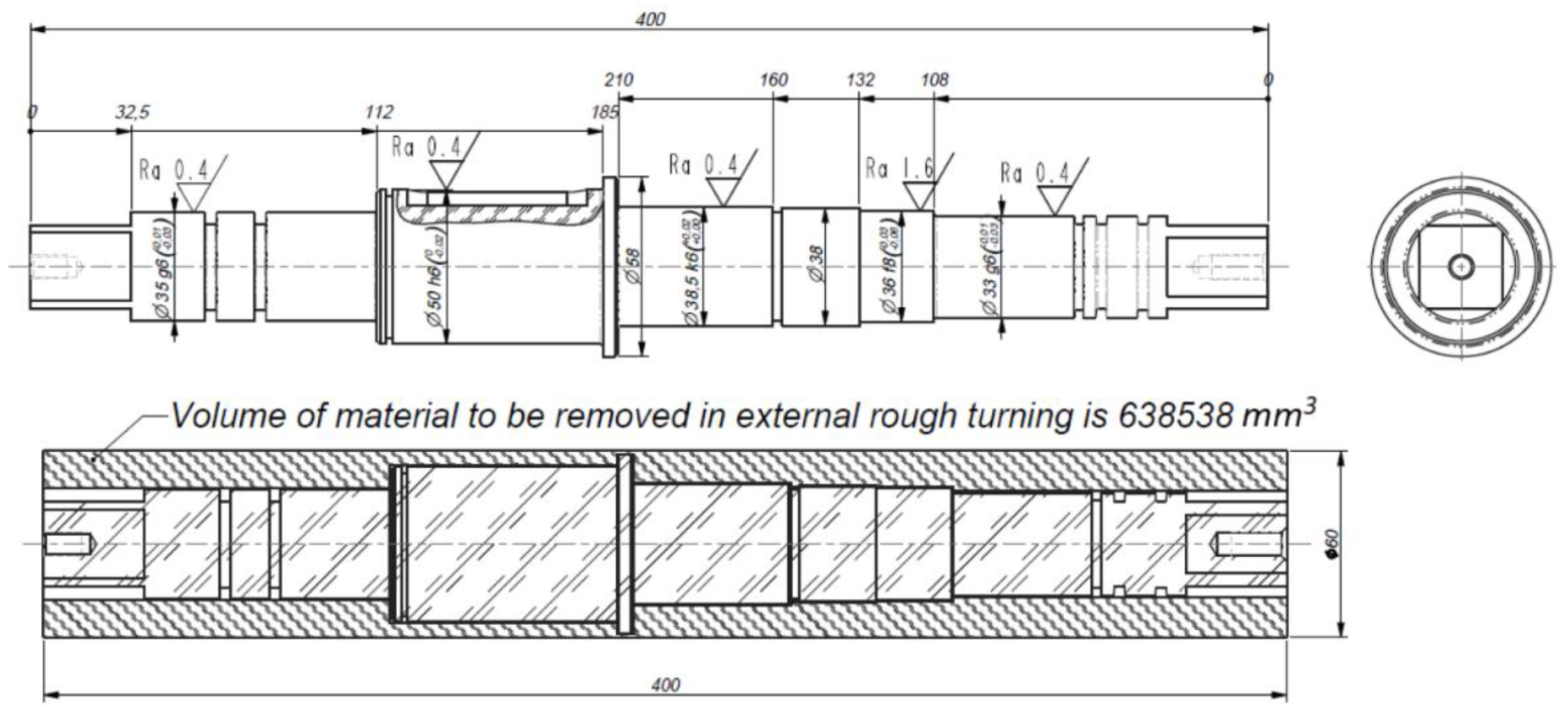
The case which motivated the research is based on a scenario from real practice, where a small manufacturing facility with limited production resources had a contract to produce 5800 driving shafts made of steel (AISI 1045) in a period of one year. Most of the milling and turning machines which the company had at its disposal were from 2000 to 2010 and it was not possible to purchase, install and put into use new, more productive machines in a short period of time. To meet the required production volume in a given period, production management suggested performing a few experiments to identify the optimal values of cutting parameters (cutting speed—vc, depth of cut—ap, and feed rate—f) for the machining operations that were critical in terms of energy consumption and engaged power (the so-called energy highly-consumptive machining operation). Even small savings in energy consumption that could be made for each machining operation would accrue into large overall savings bearing in mind the numerous repetitions over the year. Besides energy savings, it was important to measure the engaged power needed for performing the critical machining operations so the production scheduling could avoid generating electric power peaks during the specific periods of a working day. The optimal combination of cutting parameter values was the one which ensured the required productivity, i.e., material removal rate of the specific operation while the energy consumption and engaged power remained minimal. Cutting parameter ranges were selected considering recommended ranges for the insert, machine tool characteristics (motor power and maximum spindle speed), and workpiece diameter.
To avoid confusion regarding the physical quantities, measured values and parameters used in the paper, here is a list of abbreviations and their meanings (Table 2).

The Case Study

In this very particular case, the production process of the shaft shown in Figure 1 required several different turning and milling operations.
Simulations made in the CAM module of Catia V5-6 R2018 software (Dassault Systemes SE, Vélizy-Villacoublay, France) showed that external rough turning takes approximately 30% of a whole machining time, which is the greatest portion of the whole machining process. In addition, it is the operation which consumes energy far more than fine turning, so it was important to determine what the optimal combination of cutting parameter values for this operation was so that the required material removal rate (productivity) could be provided with the least energy consumption and engaged power. The surface roughness was not considered in this paper since the rough turning operation is followed by the finishing operation. In practice, cutting parameter values for rough machining operations (in this case, the turning operation) are usually selected based on experience. At the same time, it should not be neglected that performing rough and semi-finishing machining operations requires considerably higher energy consumption and engaged power compared to fine machining.
The material volume of 6.39 × 105 mm3 should be removed by external rough turning for each workpiece. Since the series is 5800 pcs/year, the total volume that should be removed by this operation is 3.7 × 109 mm3/year. On the other hand, the calculation of available time to perform external rough turning (shown below) shows that all these 3.7 × 109 mm3 should be removed in 2.208 × 10⁶ seconds, which, finally, indicates that the minimal required, target material volume removal rate (MRR) should be 1677 mm3/s.
  • Number of working days = 260 days/year;
  • Maintenance operations days = 30 days/year;
  • Number of working hours total (2 shifts) = 3680 h/year;
  • Number of operating seconds on the machine per year = 6.624 × 10⁶ s/year;
  • 30% of time is reserved for external rough turning = 2.208 106 s/year;
  • Target material volume removal rate = 1677 mm3/s.

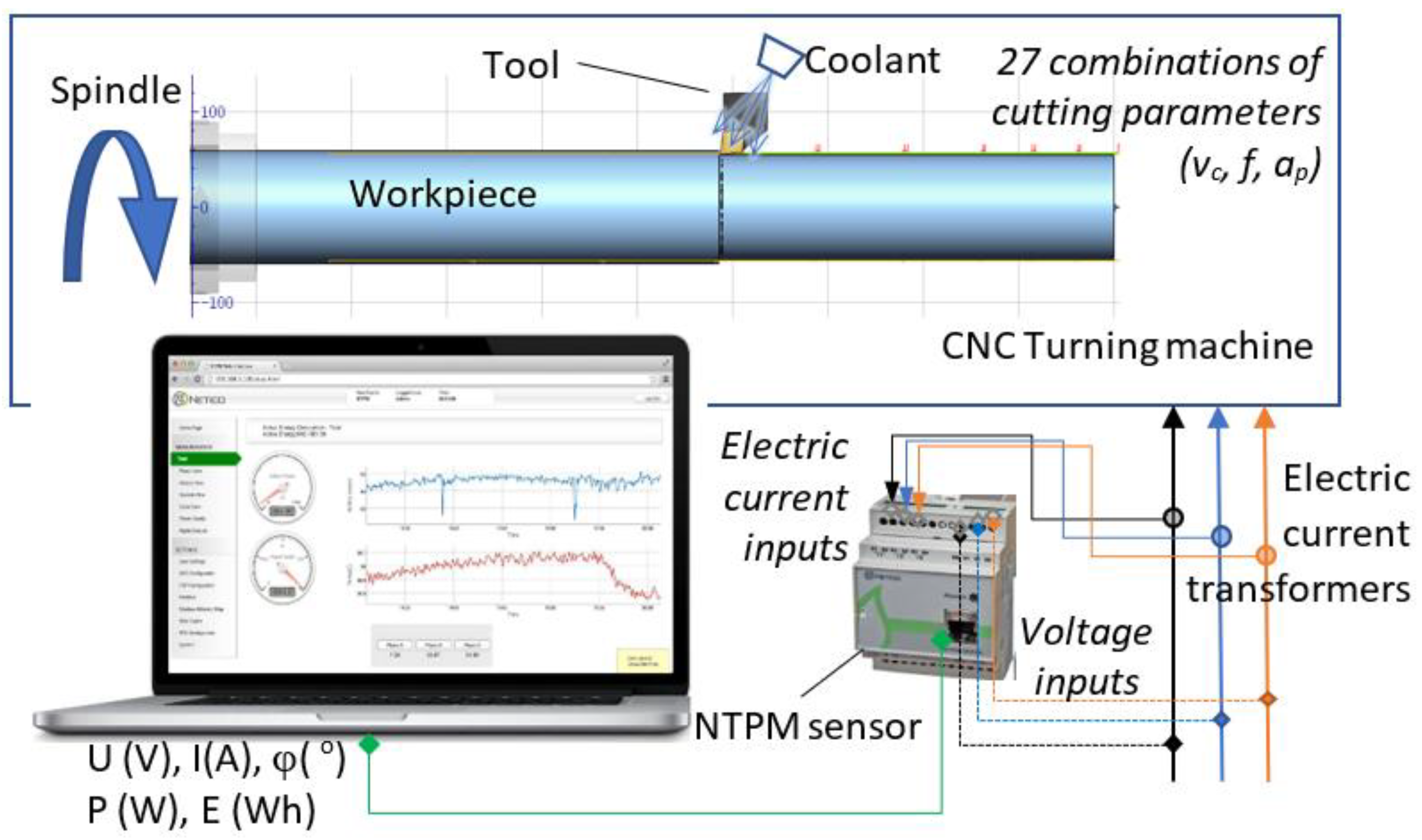
3. Experiment and Measuring Setup

To be able to develop a mathematical model that should be used for finding the optimal combination of cutting parameter values, which would ensure the target volume removal rate with minimal energy consumption, a series of experimental trials, that is, in situ measurements were done. To provide as realistic conditions for the measurements as possible, experimental workpieces (bars) were pre-machined to the same geometry as the geometry of the real workpiece that was going to be used for series production. This also allowed the mounting of the workpiece on the CNC lathe for the experiment in the same way (Figure 2). To ensure regular and uniform working conditions, the geometric (such as cylindricity and radial runout) and dimensional tolerances of each experimental workpiece were checked after pre-machining.

3.1. Materials: Workpiece, Machine, Tool System, Energy and Power Measuring Equipment

The workpiece material is AISI 1045 steel with the following properties: hardness HB = 206, specific cutting force for the unit cutting cross-section kc1 = 2000 N/mm2, mc = 0.15 (Source: SECO tools).
The CNC lathe that was used for rough external turning of the shaft was a Gildemeister NEF 520 (DMG Mori, Bielefeld, Germany) with the motor of 12 kW, maximum spindle speed of 3000 rev/min equipped with Manual Plus 4110 (Heidenhain, Traunreut, Germany) control unit. The machining was performed using a cutting fluid (cutting oil: FAM SG 15 N, ISO 6743-7, L-MHE; ISO/TS 12927, Fabrika Maziva FAM a.d. Kruševac, Serbia) that could be supplied into the cutting zone through the turret or through the flexible hose.
The cutting tool is a toolholder DCLNL 2020K 12 (Sandvik Coromant, Sandviken, Sweden) (cutting edge angle of κ = 95°, and rake angle of γ0h = −6°) with a CNMG120408-PM insert (Zhuzhou Cemented Carbide Cutting Tools Co., Zhuzhou, China), rake angle γ0i = 20°, cutting edge length le = 12 mm, nose radius rε = 0.8 mm, and grade of YBC252 (coated carbide). Effective rake angle is γ0 = 14°. The insert manufacturer recommendations for cutting parameters are:
  • ap = 0.5–4 (mm); ap_recommended = 2 mm;
  • f = 0.1–0.5 (mm/rev); f_recommended =0.25 mm/rev;
  • vc = 240–360 (m/min); vc_ recommended = 280 m/min.
Measuring schema is shown in Figure 3.
A Netico Solutions NTPM 100 sensor (Netico Solutions, Niš, Serbia) was used for energy consumption and engaged power measurement, Figure 4a. Metering current transformers are attached to three phases for electric current metering, while voltage outputs are directly attached to the sensor inputs (Figure 4b). The NTPM sensor samples the electric current and voltage every 60 (ms) and computes the total active electric energy consumption (Wh) and the total active engaged power (W).

3.2. Plan of Experiment

Considering the motor power and maximum spindle speed of the CNC lathe, which should be calculated for the minimal diameter on the real shaft for roughing Dmin = 34 mm, the upper limits of the cutting parameters ranges were adjusted as follows: fmax = 0.3 mm/rev, vc_max = 300 m/min, ap_max = 2.5 mm. On the other hand, the depth of cut should not be less than the insert nose radius re, so the lower limits of the cutting parameters ranges were set as follows: fmin = 0.1 mm/rev, vc_min = 240 m/min, ap_min = 1 mm. Cutting parameter ranges and levels used in the experiments were:
  • ap = {1, 1.75, 2.5} mm;
  • f = {0.1, 0.2, 0.3} mm/rev;
  • vc = {240, 270, 300} m/min.
Based on these values, 27 different combinations of cutting parameter values, in accordance with 33 full factorial design, were used for measuring the energy consumption and engaged power. This design was adopted since it represents a high-resolution design which enables the analysis of two-factorial interactions of the considered machining parameters as well as the development of a second order prediction model. The experiment and the measurements were conducted with three identical bars. Each bar (workpiece of initial diameter of 58 mm) was machined with one depth of cut value and nine combinations of cutting speed and feed rate values (Figure 5).
To determine the repeatability of the measured data, that is, the validity of measurement, each workpiece, after the initial machining experiment, was used for additional measurements, but with a different starting diameter (Table 3).
In this way, the complete measurements for each workpiece involved three times three different depths of cut which led to 81 measurements in total. The experiments were planned in a way to allow the NTPM sensor to record nine values of engaged power and energy consumption for each combination of cutting speed and feed rate. Since the NTPM sensor calculates and records these values every second, to get nine values, machining sequences featured by the same cutting speed and feed rate were programmed to last at least nine seconds. Each of these values (per second) was calculated as the arithmetic mean of 16 measurements (every single measurement of the electric current and voltage was done at 60 ms). Later, the specific total energy consumption in time (Wh/s) was calculated for these periods of nine seconds, i.e., for the corresponding cutting parameter combinations (Figure 6).

3.3. Measurements

The measurement of energy consumption and engaged power was done for three different working conditions:
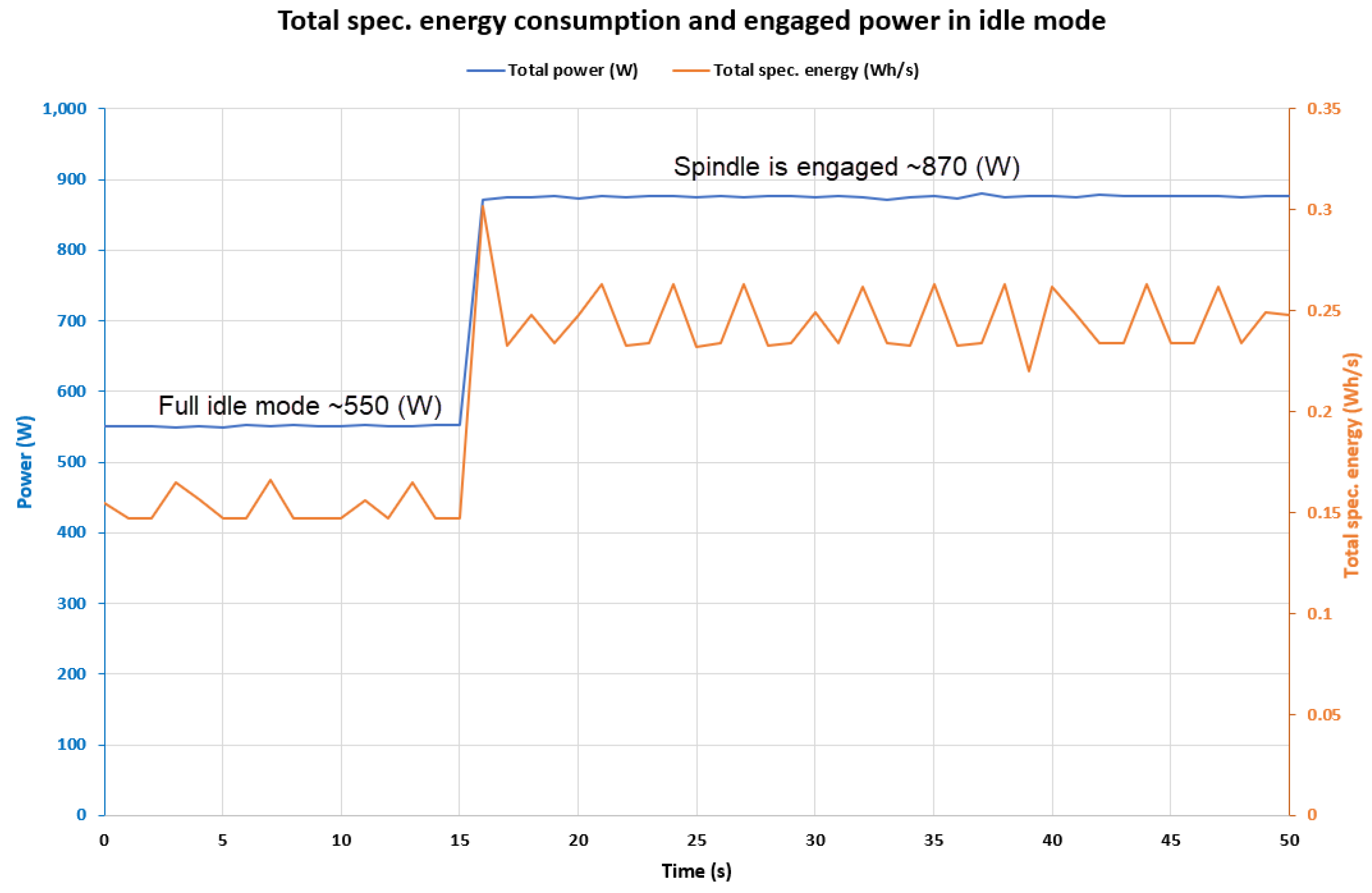
  • Idle state—the CNC lathe is turned on, but the workpiece does not rotate, nor is the coolant supplied (Figure 7).
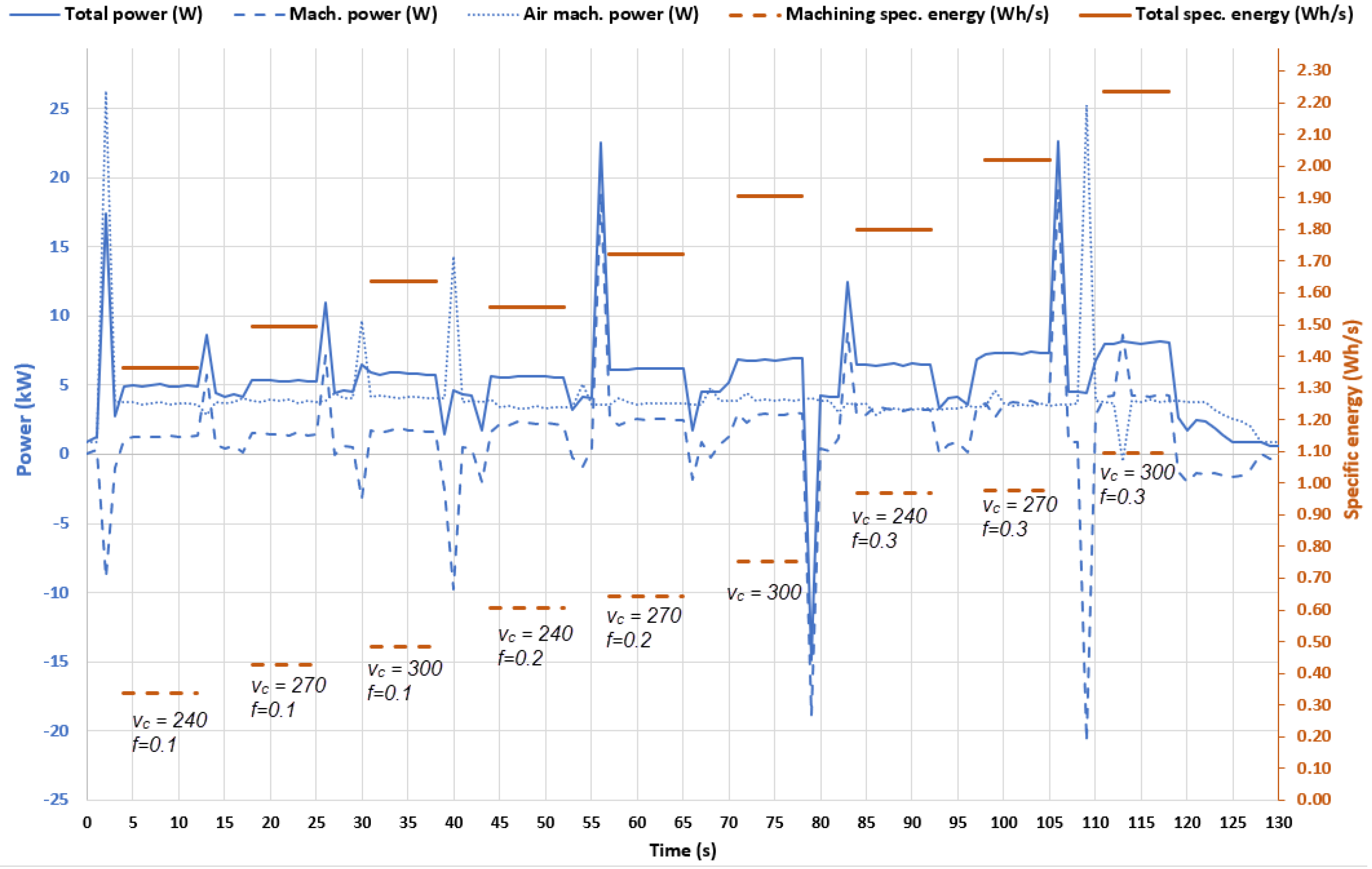
  • “Air machining”—the workpiece rotates in accordance with the NC program, the coolant floods the tool and the workpiece, the tool performs programmed movements, but the toolpath is offset 0.5 (mm) from the workpiece outer contour (Figure 8).
  • Machining—the workpiece rotates in accordance with the NC program and the turret/tool perform movements in accordance with the NC program, the tool performs programmed movements, the material is removed, the coolant floods the tool, workpiece and cutting zone (Figure 8).
Having all these measurements (Table 4) for each workpiece, it is easy to determine the difference between the energy consumption and the engaged power for all three modes. It is important to notice that the measured time-specific total energy consumption (STEC) is expressed in Wh/s and not in Wh/mm3 which is more common in the literature (denoted as SEC). Having in mind the specificity of the case and its objectives—to provide target productivity mm3/s of the specific machining operation along the production period, this unit (Wh/s) seems to be more appropriate to use. Moreover, it is possible to determine the influence of each cutting parameter on energy consumption and develop an appropriate optimization model.
Material volume removal rate given in Table 4 is calculated by using Equation (1) where feed rate is given in mm/s. (Equation (2) shows the transformation from mm/min to mm/s). Since the measurements are done for three different values of depth of cut, medium diameter Dmid is expressed as a difference between initial diameter D0 and depth of cut ap as shown in Equation (3). Finally, Equation (4) provides the well-known product of three quantities (ap mm, f mm/min, vc m/min):
M R R   mm 3 s = f s   mm s · a p mm · D m i d mm · π
f s   mm s = n   rev min · f mm rev · 1   min 60   s = v c m min · 1000   mm m D 0 ·   π   mm rev   · f mm rev · 1   min 60   s
D m i d mm = D 0 mm a p mm
M R R   mm 3 s = a p mm · f mm rev · v c m min · 1000   mm m 60   s min · 1 a p mm D 0 mm
The measured value for the engaged power for the machining working conditions applying the maximum values of cutting parameters (fmax = 0.3 mm/rev, vc_max = 300 m/min, ap_max = 2.5 mm) is 8613 W which is 11.4% greater than the engaged power obtained through the expression in Equation (5):
P = a p · f n · v c · k c 60,000 ,       where   k c = k c 1 · h m m c · 1 γ 0 100 = 7731   W
The value of engaged power for the air machining mode with the same set of cutting parameters is 3818 W. This proves that the measurements are in the expected range.
To provide better visualization of the data given in Table 4, a series of charts are presented (Figure 9, Figure 10, Figure 11 and Figure 12). These charts show the functional dependence of STEC, TEP, MRR, SEC on the combinations of cutting parameters values.
Even though, they were not the focus of this research, the appropriate measurements of roughness were done using a Mahr MarSurf XR 1 roughness measuring station (Mahr-Group Göttingen, Germany), but those data will be analysed in detail on some other occasion. However, purely informatively, a summary of the values will be given here in Table 5.

3.4. Energy Consumption Empirical Model

Based on the applied experimental design and in situ measurements of time-specific total energy consumption (STEC), the following empirical model in the form of a second-order polynomial with interactions was developed in Equation (6):
S T E C = 1.925 + 0.394 · a p + 0.387 · f + 0.206 · v c + 0.191 · a p 2 + 0.033 · f 2 + 0.06 · v c 2 + 0.153 · a p · f + 0.038 · a p · v c + 0.068 · f · v c
To process experimental the results, the least square method was applied to estimate model parameters, while statistical analysis for the assessment of the empirical model appropriateness involved the estimation of the following statistics: coefficient of determination, R2 = 0.995, predicted coefficient of determination R2pred = 0.985 and adjusted coefficient of determination R2adj = 0.992. Moreover, p values from the ANOVA analysis also proved the model’s statistical adequacy as well as the statistical significance of all model terms, excluding the quadratic effect of cutting speed and feed rate. Based on the previous analysis, one can argue that the effects of the considered parameters (depth of cut, cutting speed and feed rate) on the STEC can be analysed using the developed empirical model. For this purpose, three charts were generated to show the synergistic effects of two parameters at the time, while the third parameter was set at its middle level (Figure 13, Figure 14 and Figure 15).
From Figure 13, Figure 14 and Figure 15 one can observe that all three cutting parameters are positively correlated with the response, that is, STEC. In other words, with an increase in either depth of cut, cutting speed or feed rate, STEC increases. What can also be observed, is the fact that the effect of a given cutting parameter is more pronounced for the threshold value of another parameter. Thus, the rise in STEC is more substantial with an increase in cutting speed when the depth of cut is at its highest level ap = 2.5 mm (Figure 11) or when the feed rate is at its highest level (Figure 13). The same trend can be observed for the effect of feed rate (Figure 14 and Figure 15) and depth of cut (Figure 13 and Figure 14).
Such an effect could be expected considering that high values of cutting speed, feed rate and depth of cut result in higher consumption by spindle and feed drive motors as well as higher cutting forces in machining [34]. In that experimental investigation it was revealed that turning of 10 cm3 of 450-10S material using multi-functional machine tools NTX2000 (DMG Mori, Bielefeld, Germany) consumes from 20.9 to 55.8 Wh of electric energy (with an average of 29.8 Wh). In the present experimental investigation, the removal of 10 cm3 (106 mm3) material at lowest MRR (ap = 1 mm, vc = 240 m/min and f = 0.1 mm/rev, MRR = 0.4 cm3/s) resulted in the consumption of 34 Wh. On the other hand, with the highest MRR of 3.75 cm3/s, which is obtained under the cutting regime ap = 2.5 mm, vc = 270 m/min and f = 0.3 mm/rev, the energy consumption drops to about 9.26 Wh. The observed trend of decrease in energy consumption with an increase of MRR, i.e., decrease in machining time, is in accordance with previous experimental studies [15]. As discussed by Diaz et al., [15], a decrease in energy consumption is the result of reduced machining time, which effectively dominates over the increase in power demand due to increased loads.
In order to assess the specific energy consumption for the considered CNC lathe and machining system, the change in total energy consumption per 1 cm3 of removed material is shown in Figure 16.
As can be observed from Figure 16, the total energy consumption, which accounts for air machining and machining, was found to have a strong relationship with the MRR in the form of a power model. The total energy consumption rapidly decreases until the MRR of about 1.5 cm3/s. This is because within this region the required machining time (for removal of 1 cm3) is diminished by a factor of 3.8 (from needed 2.5 s when using ap = 1 mm, vc = 240 m/min and f = 0.1 mm/rev, to needed 0.66 s when using ap = 1.7 mm, vc = 270 m/min and f = 0.2 mm/rev). Afterwards, at MRR greater than 1.5 cm3/s, the total energy consumption decreases more slowly. Further reduction is, however, constrained by the allowable cutting regimes with respect to the machine tool and cutting tool. Generally, for the covered experimental hyper-space, one can state that the average total energy needed to remove a unit of material volume using the CNC lathe is approximately 1.64 Wh.
In finish turning of hardened stainless steel AISI 420, by using the resultant cutting force, Nur et al. [35] observed that maximal energy for the turning process is obtained at the lowest cutting speed and feed rate, which corresponds to the minimal MRR.

4. Results

Having verified the statistical validity of the energy consumption model, the main and synergistic effects of the considered parameters on the change in STEC were investigated. Also, an attempt was made to correlate the total energy consumption with MRR and it was observed that for the considered CNC lathe, the removal of 1 cm3 of material requires somewhat less than 1 Wh (when using “hard” regimes which enable high MRR and short machining time) or somewhat more than 3 Wh (when using “soft” regimes which enable low MRR and long machining time).
For a practical application, along with the analysis of changes in certain performance characteristics, which are realized through the change of cutting regimes, in many real case studies it is necessary to achieve certain goals and trade-off between performances that are, as a rule, contradictory. In that sense, the developed empirical model for the total energy consumption plays a key role as it can predict the total energy consumption for an arbitrarily selected set of cutting parameter values, and can be used together with other empirical or analytical models for optimization problem formulation in some case studies. In this way, one can increase the utilization of production capacities and market competitiveness at the same time [36].

Proposed Machining Optimization Model

In every machining process planning, there are often a number of allowable combinations of cutting parameters that can be used to machine a particular feature. The selection of these parameters is usually based on the prior experience and knowledge of process planners, recommendations of cutting tool manufacturers, expert knowledge bases, etc. However, when it comes to fulfilling different conflicting objectives, in terms of requirements related to machining characteristics, a machining optimization is needed. In accordance with the described case study, the following goal of the machining optimization model was set:
Determine the optimal combination of values of cutting parameters ap, vc and f that will ensure minimum consumption of time-specific total energy (STEC Wh/s) while the material removal rate (MRR) should be kept at 1677 mm3/s. Therefore, the following nonlinear optimization problem with constraints was proposed:
Minimize   [ STEC ( Wh / s ) ]   Subject   to   MRR = a p · f · v c = 1677   mm 3 / s 1 a p 2.5   mm ,   240 v c 300   m / min ,   0.1 f 0.3   m / rev
In the present study, considering the optimization problem type and complexity, a sequential quadratic programming (SQP) method with active set strategy is adopted to determine optimal values of depth of cut, cutting speed and feed rate. This optimization approach is one the best approaches for solving constrained nonlinear optimization problems [37]. More details regarding this optimization method with applications for solving engineering optimization problems are given elsewhere [38].
By solving the constrained non-linear optimization problem, as given in Equation (7), optimal values of cutting parameters (ap, vc and f) were reached. The optimization solution suggests that the combination of ap = 1.647 mm, vc = 240 m/min and f = 0.255 mm/rev provides the minimal time-specific total energy consumption of 1.852 Wh/s and the target MRR of 1677 mm3/s is achieved. In order to verify the determined optimization solution this particular combination of cutting parameters values was set on the CNC lathe and another validation experimental trial was performed (Figure 17).
The mean value for the specific total energy consumption, calculated from the measured data of the specific total energy consumption for optimal set of cutting parameters values is 1.826 Wh/s. The measured STEC is 1.4% lower than the value predicted by the optimization model.

5. Discussion

The comparison of the total energy consumption values for the entire series of shafts (Ets) for the determined optimization solution and the cutting regime recommended by the cutting tool manufacturer is given in Table 6.
In accordance with the calculated target machining time for the external rough turning of 2.208 106 s/year and minimum target productivity of 1677 mm3/s, the optimal combination of cutting parameter values gives STEC 1.852 Wh/s, which means that for the entire series of shafts (3.7 × 109 mm3) the CNC lathe will consume 4089 kWh. On the other hand, for the recommended cutting regime (ap = 2 mm, f = 0.25 mm/rev and vc = 280 m/min), the productivity is 2333 mm3/s, so the total volume of material (3.7 × 109 mm3) can be removed in 1.587 × 10⁶ s which is 28.1% shorter than the target machining time. Since the STEC for this combination of cutting parameter values is 2.389 Wh/s (obtained from the STEC prediction model), to remove all the material in rough external turning the same CNC lathe will consume 3792 kWh. Compared to the total energy consumption for the determined optimization solution, this combination gives better performance, i.e., energy saving of 7.83%. Considering that the optimal set of values of cutting parameters is chosen for the target minimum productivity, there is a risk of completing the job just-on-time. Should a small deviation in the production plan appear, this would be enough for the facility not to be able to produce a required number of shafts if it adheres to the optimal values of the cutting parameters. For the case of applying the combination of cutting parameter values that gives the minimum of SEC (as measured, this is 9.527 × 10⁻⁴ Wh/mm3 for ap = 2.5 mm, f = 0.3 mm/rev and vc = 270 m/min), time saving goes up to 48% and total energy consumption for the entire series of shafts is even 15.9% lower compared to the determined optimization solution (for targeted MRR). However, the engaged power for this case reaches the upper limit of CNC lathe motor power and, even more importantly, there is a great risk for the workshop to exceed the agreed maximum of engaged power (engaged power peaks). Moreover, the regimes characterized by higher cutting speed and greater depth of cut can significantly decrease tool life, which, ultimately, can lead to longer production times as more frequent tool changes will be required.
For the researched experimental hyper-space, it can be concluded that the specific total energy consumption is mostly affected by depth of cut, followed by feed rate and cutting speed. Although one can expect a constant positive correlation between the considered parameters and process performance, one may not guarantee that, in another experimental hyper-space or machining system, the order of influence of the parameters would be the same. Given that machining processes are complex, stochastic, and diffuse, one may expect different system behaviors in different experimental hyper-spaces, which justifies numerous empirical studies even for the most explored materials. Considering that the total consumed energy decreases by the power model (Figure 16) with an increase in MRR, in machining practice one should strive to achieve the highest possible MRR; at the same time, one must also consider the possibilities of the used machine tool, cutting tool as well as imposed criteria, related to manufacturing time, cost, quality characteristics etc.
The second important observation is the one related to the energy consumption for the so-called idle state. It is obvious from the measurements (Figure 7) that the CNC lathe consumes a large portion of total energy when it does not operate (rotate the workpiece) which may be considered as the pure waste of the energy. Due to this, machine tool manufacturers should consider technical solutions which can minimize energy consumption in the so-called idle state as well as during the accelerations/decelerations of masses (workpieces and tool turrets). In addition, concerning the engaged power peaks, the accelerations of the CNC lathe components during machining contribute considerably and one should have that in mind when the production process is being planned. Having the possibility to measure electric current and voltage every 60 milliseconds and less, the focus of the research in future will move to the transient processes such as plunging the tool into the material and other such acceleration characteristics of the rapid movements.

6. Conclusions

Even though, there are numerous studies related to the optimization of cutting parameters as well as recommendations given by cutting tool manufacturers for this or some other material, in practice, often, there are specific limitations related to the production conditions that make the recommended cutting parameter values inapplicable. Whether it is production resource limitation (low machine performance or lack of a proper tool) or short production time or limited power level that a workshop can engage, when the challenge for some reason is to adjust the recommendations of the cutting parameter values, then it can be very useful to have a prepared method for determining the optimal set of cutting parameter values adjusted to specific production conditions. Having in mind this challenge and the research that was conducted, here are the main findings, briefly stated:
  • The main difference from the majority of previous studies comes from the determination to deal with a specific real-practice case, which concerns a lot of small workshops limited by the existing production facility resources to find the optimal selection of cutting parameter values that are adjusted to their limitations. This kind of optimization is especially important for the machining operations that consume a large amount of energy and engage high power.
  • The methods used for both modelling and optimization are not new by themselves, but the presented approach of determining the optimal cutting parameters against the additional constraints seems very usable and efficient in real practice. Thus, the practical relevance of the research is that it can be seen as a kind of template procedure that is developed for determination of optimal selection of cutting parameter values adjusted to the specific limitations originating from the real production conditions. Of course, it is worthwhile conducting the procedure for serial production where numerous repetitions of the critical operation justify it.
  • The advantage of the applied procedure is the continuous change of parameters in real time and the direct monitoring of power and energy consumption. In this way, the influence of the parameters, as well as the area of research, can be determined easily. In addition, the advantage is that this method of measurement can indicate in real time whether there has been any significant wear of the tool, which would be reflected in an increase in power for the cutting summary constants;
  • The proposed template procedure represents a general approach which can also be applied to other workpiece materials, cutting tool materials and machining processes, operations and features (drilling, chamfering, facing, boring, finish turning, multi-pass turning, etc).

Author Contributions

Conceptualization, M.S., M.M. and M.T.; methodology, M.S., M.M. and M.T; software, M.S.; validation, M.T., R.T. and M.M.; formal analysis, M.S.; investigation, M.S., M.T. and R.T.; resources, M.T., R.T. and M.M.; data curation, M.S.; writing—original draft preparation, M.S. and R.T.; writing—review and editing, M.S., M.M., M.T. and R.T.; visualization, M.S.; supervision, M.T.; project administration, R.T.; All authors have read and agreed to the published version of the manuscript.

Funding

This research was funded by Ministry of Education, Science and Technological Development of the Republic of Serbia, grant number No. 451-03-68/2022-14/ 200109.

Institutional Review Board Statement

Not applicable.

Informed Consent Statement

Not applicable.

Data Availability Statement

Not applicable.

Acknowledgments

The authors are grateful to Netico-Solutions for technical support preparing the experiments.

Conflicts of Interest

The authors declare no conflict of interest.

References

  1. Zolfani, S.H.; Bazrafshan, R.; Akaberi, P.; Yazdani, M.; Ecer, F. Combining the suitability-feasibility-acceptability (SPA) strategy with the MCDM approach. Facta Univ. Ser. Mech. Eng. 2021, 19, 579–600. [Google Scholar]
  2. Stanojković, J.; Radovanović, M. Influence of the cutting parameters on force moment and surface roughness in the end milling of aluminum 6082-T6. Facta Univ. Ser. Mech. Eng. 2022, 20, 157–165. [Google Scholar] [CrossRef]
  3. Kara, S.; Li, W. Unit process energy consumption models for material removal processes. CIRP Ann. Manuf. Technol. 2011, 60, 37–40. [Google Scholar] [CrossRef]
  4. Jeswiet, J.; Kara, S. Carbon emissions and CESTM in manufacturing. CIRP Ann. Manuf. Technol. 2008, 57, 17–20. [Google Scholar] [CrossRef]
  5. Gutowski, T.; Dahmus, J.; Thiriez, A. Electrical energy requirements for manufacturing processes. In Proceedings of the 13th CIRP International Conference of Life Cycle Engineering, Lueven, Belgium, 31 May–2 June 2006. [Google Scholar]
  6. Duflou, J.R.; Sutherland, J.W.; Dornfeld, D.; Herrmann, C.; Jeswiet, J.; Kara, S.; Hauschild, M.; Kellens, K. Towards energy and resource efficient manufacturing: A processes and systems approach. CIRP Ann. Manuf. Technol. 2012, 61, 587–609. [Google Scholar] [CrossRef] [Green Version]
  7. Warsi, S.S.; Jaffery, S.H.I.; Ahmad, R.; Khan, M.; Ali, L.; Agha, M.H.; Akram, S. Development of energy consumption map for orthogonal machining of Al 6061-T6 alloy. Proc. Inst. Mech. Eng. Part B J. Eng. Manuf. 2018, 232, 2510–2522. [Google Scholar] [CrossRef]
  8. Zhou, L.; Li, J.; Li, F.; Meng, Q.; Li, J.; Xu, X. Energy consumption model and energy efficiency of machine tools: A comprehensive literature review. J. Clean. Prod. 2016, 112, 3721–3734. [Google Scholar] [CrossRef]
  9. Zhao, G.Y.; Liu, Z.Y.; He, Y.; Cao, H.J.; Guo, Y.B. Energy consumption in machining: Classification, prediction, and reduction strategy. Energy 2017, 133, 142–157. [Google Scholar] [CrossRef]
  10. Camposeco-Negrete, C. Optimization of cutting parameters using Response Surface Method for minimizing energy consumption and maximizing cutting quality in turning of AISI 6061 T6 aluminum. J. Clean. Prod. 2015, 91, 109–117. [Google Scholar] [CrossRef]
  11. Kumar, R.; Singh, S.; Sidhu, A.S.; Pruncu, C.I. Bibliometric analysis of Specific Energy Consumption (SEC) in machining operations: A sustainable response. Sustainability 2021, 13, 5617. [Google Scholar] [CrossRef]
  12. Li, L.; Li, C.; Tang, Y.; Yi, Q. Influence factors and operational strategies for energy efficiency improvement of CNC machining. J. Clean. Prod. 2017, 161, 220–238. [Google Scholar] [CrossRef]
  13. Balogun, V.A.; Mativenga, P.T. Modelling of direct energy requirements in mechanical machining processes. J. Clean. Prod. 2013, 41, 179–186. [Google Scholar] [CrossRef]
  14. Mori, M.; Fujishima, M.; Inamasu, Y.; Oda, Y. A study on energy efficiency improvement for machine tools. CIRP Ann. Manuf. Technol. 2011, 60, 145–148. [Google Scholar] [CrossRef]
  15. Diaz, N.; Redelsheimer, E.; Dornfeld, D. Energy consumption characterization and reduction strategies for milling machine tool use. In Proceedings of the Glocalized Solutions for Sustainability in Manufacturing: Proceedings of the 18th CIRP International Conference on Life Cycle Engineering, Braunschweig, Germany, 2–4 May 2011; pp. 263–267. [Google Scholar]
  16. He, Y.; Liu, F.; Wu, T.; Zhong, F.P.; Peng, B. Analysis and estimation of energy consumption for numerical control machining. Proc. Inst. Mech. Eng. Part B J. Eng. Manuf. 2012, 226, 255–266. [Google Scholar] [CrossRef]
  17. Xie, J.; Liu, F.; Qiu, H. An integrated model for predicting the specific energy consumption of manufacturing processes. Int. J. Adv. Manuf. Technol. 2016, 85, 1339–1346. [Google Scholar] [CrossRef]
  18. Zhao, G.; Zhao, Y.; Meng, F.; Guo, Q.; Zheng, G. Prediction model of machine tool energy consumption in hard-to-process materials turning. Int. J. Adv. Manuf. Technol. 2020, 106, 4499–4508. [Google Scholar] [CrossRef]
  19. Jozić, S.; Dumanić, I.; Bajić, D. Experimental analysis and optimization of the contorllable parameters in turning of en AW-2011 alloy: Dry machining and alternative cooling techniques. Facta Univ. Ser. Mech. Eng. 2020, 18, 13–29. [Google Scholar]
  20. Rajemi, M.F.; Mativenga, P.T.; Aramcharoen, A. Sustainable machining: Selection of optimum turning conditions based on minimum energy considerations. J. Clean. Prod. 2010, 18, 1059–1065. [Google Scholar] [CrossRef]
  21. Guo, Y.; Loenders, J.; Duflou, J.; Lauwers, B. Optimization of energy consumption and surface quality in finish turning. Procedia CIRP 2012, 1, 512–517. [Google Scholar] [CrossRef]
  22. Lu, C.; Gao, L.; Li, X.; Chen, P. Energy-efficient multi-pass turning operation using multi-objective backtracking search algorithm. J. Clean. Prod. 2016, 137, 1516–1531. [Google Scholar] [CrossRef] [Green Version]
  23. Bagaber, S.A.; Yusoff, A.R. Multi-objective optimization of cutting parameters to minimize power consumption in dry turning of stainless steel 316. J. Clean. Prod. 2017, 157, 30–46. [Google Scholar] [CrossRef] [Green Version]
  24. Su, Y.; Zhao, G.; Zhao, Y.; Meng, J.; Li, C. Multi-Objective optimization of cutting parameters in turning AISI 304 austenitic stainless steel. Metals 2020, 10, 217. [Google Scholar] [CrossRef]
  25. Zhu, Z.; Buck, D.; Guo, X.; Xiong, X.; Xu, W.; Cao, P. Energy efficiency optimization for machining of wood plastic composite. Machines 2022, 10, 104. [Google Scholar] [CrossRef]
  26. Salur, E.; Kuntoglu, M.; Asian, A.; Pimenov, D.Y. The effects of MQL and dry environment on tool wear, cutting temperature, and power consumption during end milling of AISI 1040 steel. Metals 2021, 11, 1674. [Google Scholar] [CrossRef]
  27. Kant, G.; Sangwan, K.S. Prediction and optimization of machining parameters for minimizing power consumption and surface roughness in machining. J. Clean. Prod. 2014, 83, 151–164. [Google Scholar] [CrossRef]
  28. Sangwan, K.S.; Kant, G. Optimization of machining parameters for improving energy efficiency using Integrated Response Surface Methodology and Genetic Algorithm Approach. Procedia CIRP 2017, 61, 517–522. [Google Scholar] [CrossRef]
  29. Sidhu, A.S.; Singh, S.; Kumar, R.; Pimenov, D.Y.; Giasin, K. Prioritizing Energy-Intensive Machining Operations and Gauging the Influence of Electric Parameters: An Industrial Case Study. Energies 2021, 14, 4761. [Google Scholar] [CrossRef]
  30. Zębala, W.; Struzikiewicz, G.; Słodki, B. Reduction of Power Consumption by Chip Breakability Control in Ti6Al4V Titanium Alloy Turning. Materials 2020, 13, 2642. [Google Scholar] [CrossRef]
  31. Kuntoglu, M.; Saglam, H. Investigation of progressive tool wear for determining of optimized machining parameters in turning. Measurement 2019, 140, 427–436. [Google Scholar] [CrossRef]
  32. Usca, U.A.; Sap, S.; Uzun, M.; Kuntoglu, M.; Salur, E.; Karabiber, A.; Pimenov, D.Y.; Giasin, K.; Wojciechowski, S. Estimation, optimization and analysis based investigation of the energy consumption in machinability of ceramic-based metal matrix composite materials. J. Mater. Res. Technol. 2022, 17, 2987–2998. [Google Scholar] [CrossRef]
  33. Qasim, A.; Nisar, S.; Shah, A.; Khalid, M.S.; Sheikh, M.A. Optimization of process parameters for machining of AISI-1045 steel using Taguchi design and ANOVA. Simul. Model. Pract. Theory 2015, 59, 36–51. [Google Scholar] [CrossRef]
  34. Oda, Y.; Fujishima, M.; Takeuchi, Y. Energy-saving machining of multi-functional machine tools. Int. J. Autom. Technol. 2015, 9, 135–142. [Google Scholar] [CrossRef]
  35. Nur, R.; Yusof, N.M.; Sudin, I.; Nor, F.M.; Kurniawan, D. Determination of energy consumption during turning of hardened stainless steel using resultant cutting force. Metals 2021, 11, 565. [Google Scholar] [CrossRef]
  36. Jozić, S.; Bajić, D.; Dumanić, I.; Bagavac, Ž. Optimization for an efficient and highly productive turning process. Rep. Mech. Eng. 2021, 2, 212–221. [Google Scholar] [CrossRef]
  37. Liu, X.W. Global convergence on an active set SQP for inequality constrained optimization. J. Comput. Appl. Math. 2005, 180, 201–211. [Google Scholar] [CrossRef]
  38. Belegundu, A.D.; Chandrupatla, T.R. Optimization Concepts and Applications in Engineering, 3rd ed.; Cambrige University Press: Cambrige, UK, 2019. [Google Scholar]
Figure 1. The shaft geometry and the volume of workpiece material to be removed by rough external turning (all dimensions shown in the figure are given in mm except the average roughness values, which are given in μm).
Metals 12 01793 g001
Figure 2. The workpiece geometry and the way of mounting (clamping and supporting). The dimensions shown in the figure are given in mm.
Metals 12 01793 g002
Figure 3. Schematic of measuring the (total) electric energy consumption and engaged power of the turning machine.
Metals 12 01793 g003
Figure 4. The current and voltage measurement setup: (a) installation of three metering current transformers and NTPM sensor in the energy cabinet of the CNC lathe. (b) NTPM sensor receives, processes and sends measured data through the ethernet.
Metals 12 01793 g004
Figure 5. Machining plan for each workpiece was performed with one depth of cut.
Metals 12 01793 g005
Figure 6. Recording energy consumption and engaged power measurements was done at discrete moments every second. The figure also shows how total engaged power (TEP) and specific total energy consumption in time (STEC) were calculated.
Metals 12 01793 g006
Figure 7. Total specific energy consumption and engaged power for the idle mode.
Metals 12 01793 g007
Figure 8. Total engaged power and mean specific energy consumption for the air-machining mode and machining mode for the workpiece machined with the depth of cut of 1 mm.
Metals 12 01793 g008
Figure 9. Total time-specific energy consumption (STEC) in relation to the selected range of ap, f, vc.
Metals 12 01793 g009
Figure 10. Total engaged power (TEP) in relation to the selected range of ap, f, vc.
Metals 12 01793 g010
Figure 11. Material volume removal rate (MRR) in relation to the selected range of ap, f, vc.
Metals 12 01793 g011
Figure 12. Specific energy consumption (SEC) as a ratio of time-specific total energy consumption per material volume removal rate (mm3/s) in relation to the selected range of ap, f, vc.
Metals 12 01793 g012
Figure 13. Change in STEC with respect to cutting speed and depth of cut.
Metals 12 01793 g013
Figure 14. Change in STEC with respect to feed rate and depth of cut.
Metals 12 01793 g014
Figure 15. Change in STEC with respect to feed rate and cutting speed.
Metals 12 01793 g015
Figure 16. Total energy consumption as a function of MRR (material volume removal rate is given in cm3, 1 cm3 = 103 mm3).
Metals 12 01793 g016
Figure 17. Measurement of the STEC for optimal set of cutting parameters values.
Metals 12 01793 g017
Table 1. Summary of work related to parameter optimization.
RefAuthors (Year)Material
(Machining Process)
Input Parameters 1Output
Parameters
Optimization Methodology
[20]Rajemi et al. (2010)ASI 1040 steel (turning, dry conditions)vc (300, 400, 500 m/min), f (0.15 mm/rev), ap (1 mm)Energy consumption, tool wear-
[21]Guo et al. (2012)11SMnPb30 steel, AlCuMgPb aluminum (finish turning, dry conditions)vc (60~800 m/min), f (0.05~0.3 mm/rev), ap (0.5~2 mm)Energy consumption (total specific energy), surface roughness-
[10]Camposeco-Negrete (2015)AISI 606 T6 aluminum (rough turning, wet conditions)vc (266–434 m/min), f (0.12–0.28 mm/rev), ap (0.66–2.34 mm)Specific energy consumption (SEC), surface roughnessMRRCentral composite design (for experiment setup), RSM
[22]Lu et al. (2016)C45 carbon steel forging bar (rough and finish multi-pass turning, wet conditions)vc (50–500 m/min), f (0.1–0.9 mm/rev), ap (1–3 mm), number of roughing passes (1–7), tool life, etc.Energy consumption, machining precisionMOBSA
[23]Bagaber and Yusoff (2017)AISI 316 stainless steel (turning, dry conditions)vc (89.5–190.4 m/min), f (0.066–0.23 mm/rev), ap (0.6–1.6 mm)Energy consumption, surface roughness, tool wearRSM
[7]Warsi et al. (2018)Al 6061-T6 alloy (orthogonal pipe machining, dry conditions)vc (250, 500, 750, 1000 m/min), f (0.1, 0.2, 0.3, 0.4 mm/rev)Specific energy consumption, chip formation-
[24]Su et al. (2020)AISI 304 austenitic stainless steel, (turning, wet conditions)vc (50–80 m/min), f (0.15–0.35 mm/rev), ap (0.2–2.2 mm)Specific energy consumption, surface roughnessMRRTaguchi method, GRA, RSM
[31]Kuntoglu and Saglam (2019)AISI 1050, (turning, dry conditions)vc (135, 194, 207 m/min), f (0.171, 0.214. 0.256 mm/rev), tool tipCutting tool, tangential cutting force, acoustic emissionTaguchi method, ANOVA
[32]Usca et al. (2022)Cu/B-CrC composites (milling)vc (125, 175 m/min), f (0.2, 0.4 mm/rev), reinforcement ratio (0, 5, 10, 15%)Energy consumptionTaguchi method, fuzzy inference system
1 vc—cutting speed, f—feed rate, ap—depth of cut.
Table 2. Abbreviations, meanings and units of values used in the paper.
AbbreviationMeaningUnit
apDepth of cutmm
fFeed ratemm/rev
vcCutting speedm/min
MRR Material (volume) removal ratecm3/s, mm3/s
TECTotal active electric energy consumptionWh
SECSpecific energy consumptionWh/mm3
STECSpecific total energy consumption in time (or Time-specific total energy consumption)Wh/s
TEPTotal active engaged powerW
EtsTotal energy consumption for the particular shaftkWh
Table 3. Series of initial and additional measurements that were used to check the validity of data.
Workpiece NumberInitial MeasurementAdditional Measurements
From D0 to D1, apFrom D0′ to D1′, apFrom D0″ to D1″, ap
1st workpiece58 to 56, ap = 1 mm56 to 52.6 ap = 1.7 mm52.6 to 47.6 ap = 2.5 mm
2nd workpiece58 to 54.6, ap = 1.7 mm54.6 to 52.6, ap = 1 mm52.6 to 47.6, ap = 2.5 mm
3rd workpiece58 to 53, ap = 2.5 mm53 to 51, ap = 1 mm51 to 47.6, ap = 1.7 mm
Table 4. Cutting parameter combinations and corresponding measured values of total engaged power (TEP) and time-specific total energy consumption (STEC) as well as the calculated values of material volume removal rate (MRR) and specific total energy consumption (SEC) in terms of material removal.
ap
(mm)
f
(mm/rev)
vc
(m/min)
MRR
(mm3/s)
TEP
(W)
STEC
(Wh/s)
SEC
(Wh/mm3)
10.1240393.104935.061.373.474 × 10−3
10.1270442.245322.911.493.376 × 10−3
10.1300491.385835.521.643.329 × 10−3
10.2240786.215608.111.551.977 × 10−3
10.2270884.486175.241.721.949 × 10−3
10.2300982.766837.591.911.939 × 10−3
10.32401179.316492.261.801.526 × 10−3
10.32701326.727299.552.021.523 × 10−3
10.33001474.148051.622.231.515 × 10−3
1.70.1240649.975512.271.512.326 × 10−3
1.70.1270731.225900.721.642.249 × 10−3
1.70.1300812.476264.621.742.140 × 10−3
1.70.22401299.956199.091.711.316 × 10−3
1.70.22701462.446867.041.911.309 × 10−3
1.70.23001624.937592.232.121.305 × 10−3
1.70.32401949.927428.402.051.052 × 10−3
1.70.32702193.668340.292.301.050 × 10−3
1.70.33002437.409136.012.561.051 × 10−3
2.50.1240955.366533.281.811.895 × 10−3
2.50.12701074.787166.881.981.845 × 10−3
2.50.13001194.207772.732.131.784 × 10−3
2.50.22401910.718184.402.281.194 × 10−3
2.50.22702149.559082.342.521.170 × 10−3
2.50.23002388.3910,018.382.781.165 × 10−3
2.50.32402866.079995.082.789.699 × 10−4
2.50.32703224.3311,216.103.079.528 × 10−4
2.50.33003582.5912,432.053.479.681 × 10−4
Table 5. Summary of measurements of average roughness for the whole range of values of cutting speed vc = {240, 270, 300} m/min, and depth of cut ap = {1, 1.7, 2.5} mm.
Average Roughnessf = 0.1 (mm/rev)f = 0.2 (mm/rev)f = 0.3 (mm/rev)
Ra min0.945 (μm)1.238 (μm)2.332 (μm)
Ra max0.986 (μm)1.522 (μm)2.789 (μm)
Table 6. Comparison of obtained results for different cutting parameters’ values.
Cutting Parametersap (mm)vc (m/min)f (mm/rev)MRR (mm3/s)Time 1
(s)
STEC (Wh/s)Ets (kWh)
Determined optimization solution for minimum STEC and target MRR1.6472400.25516772.208 × 1061.8524089
Recommended cutting regime22800.2523331.587 × 1062.3893792
According to minimum measured value of SEC (Wh/mm3) (Table 2 and Figure 10)2.52700.332241.1486 × 1063.0723528
1 Time to remove 3.7 × 109 mm3 of material.
Publisher’s Note: MDPI stays neutral with regard to jurisdictional claims in published maps and institutional affiliations.

