Article

Simulation Study of Ultrasonic Elliptical Vibration Cutting of TiC Particle-Reinforced Titanium Matrix Composites

1
School of Mechanical Engineering, Yancheng Institute of Technology, Yancheng 224051, China
2
College of Mechanical and Electrical Engineering, Nanjing University of Aeronautics and Astronautics, Nanjing 210016, China
*
Author to whom correspondence should be addressed.
Metals 2022, 12(10), 1769; https://doi.org/10.3390/met12101769
Submission received: 13 September 2022 / Revised: 12 October 2022 / Accepted: 19 October 2022 / Published: 21 October 2022
(This article belongs to the Special Issue Advanced Metal Cutting Technology and Tools)

Abstract

:
In order to investigate the characteristics of elliptical ultrasonic vibration cutting of TiC particle-reinforced titanium matrix composites, a two-dimensional thermodynamic coupled finite element cutting model was established based on the Johnson-Cook intrinsic structure model using ABAQUS simulation software, and the changes in cutting force, cutting temperature, machined surface shape, and particle fragmentation were obtained under the traditional cutting method and ultrasonic elliptical vibration cutting method. The results show that under the same process parameters, ultrasonic elliptical vibration cutting is better than conventional cutting in terms of surface profile; the stress direction tends to be horizontal during cutting and the TiC particles are mainly removed by cutting off. The average cutting force is significantly lower than conventional cutting, with a maximum reduction of 60%. The cutting temperature is also reduced, with a reduction of approximately 17.6%.

1. Introduction

Titanium alloys are mainly used in transportation (mainly aerospace structures) and medicine [1,2] due to their unique properties. Among them, particle-reinforced titanium matrix composites (hereafter referred to as PTMCs). It is a composite material obtained by adding high-strength, high-hardness, and high-modulus hard-particle-reinforced phases to the titanium alloy as the matrix. Compared with traditional titanium alloys, it has superior physical and mechanical properties such as creep resistance and high temperature resistance. It is widely used in the fields of aerospace, automotive machinery, and medical devices [3]. However, PTMCs make the material more resistant to deformation due to the presence of the high-strength ceramic particle reinforcement phase. This makes it difficult to machine workpieces with complex contour shapes. Moreover, the room temperature plasticity of the material is very poor, which increases the difficulty of heat deformation processing. Therefore, further research on the processing technology of PTMCs is of great practical importance [4]. Additionally, ultrasonic vibration cutting can effectively improve cutting performance due to intermittent cutting, which can significantly improve cutting forces [5], among ultrasonic vibration cutting, ultrasonic elliptical vibration cutting (UEVCT) is widely recognized by researchers for its unique cutting characteristics. Ultrasonic elliptical vibration-assisted cutting is a rotational cutting engineering based on ordinary cutting (CCT) processing that uses an ultrasonic vibration driver to excite the cutting tool to generate additional forced vibrations in two directions and adjust the appropriate phase to form an elliptical motion trajectory so that the cutting edge of the tool shows an elliptical trajectory [6]. This type of separate cutting can effectively inhibit the generation of chip tumors, and also avoid violent friction between the rear tool face and the machined surface, which in turn significantly reduces the cutting force and cutting zone temperature, reduces the residual stress on the workpiece surface, thus achieving the purpose of improving the surface machining quality of difficult-to-machine materials and alleviating tool wear [7].
With the improvement of computer hardware and software performance, finite element analysis software can greatly improve the efficiency of research; domestic and foreign scholars have made a lot of research with the help of finite element technology at the same time to achieve many very valuable reference research results: Muhammad et al. [8] established a 3D finite element model of a titanium-based high-temperature alloy to compare ultrasonic vibration-assisted cutting with conventional cutting, and found that the tangential and radial components of ultrasonic vibration cutting forces were reduced by 65% and 57%, respectively, compared to conventional cutting in both directions. Dong et al. [9] carried out ultrasonic elliptical vibration cutting simulation analysis on an aluminum alloy using ABAQUS software, and compared with traditional cutting, it was found that the Mises stress distribution of ultrasonic elliptical vibration cutting is more conducive to chip formation and excretion, which can significantly reduce the cutting force and reduce the cutting temperature to a certain extent. Tan et al. [10] used a CCT process and UEVCT process for micro-grooving experiments on titanium alloy surfaces. It was found that irregular defects such as bumps, hollows, and tear marks appeared on the surface machined by CCT compared to the surface machined by UEVCT, which had almost no surface defects, indicating that the application of UEVCT technology significantly improved the surface integrity of the cutting process. Tong et al. [11] used an ultrasonic longitudinal-torsional composite vibration machining method and found that the tool’s rear-face wear was reduced after the application of ultrasound, the surface roughness of the workpiece was reduced, and the tool life was extended. Zhang et al. [12] conducted comparative cutting experiments on 7050-T7451 aluminum alloy and the results showed that the cutting force required by UEVCT was approximately three-fifths of that required by CCT under the same cutting parameters and its cutting surface quality was much higher than that of CCT. Usman et al. [13] used a numerical simulation to model the effect of machining variables on surface functional parameters and showed that the UEVCT process was more beneficial than the CCT process in improving the tribological properties of the machined surface. Through the above scholars’ results, it can be found that the cutting performance of ultrasonic elliptical vibration cutting is much better than that of traditional machining, but most scholars are currently concentrating on the study of elliptical vibration cutting machining of aluminum-based or other metal-based composites, and there are still few simulation studies for PTMCs [8,9,10,11,12,13,14].
Therefore, in this paper, a comparative simulation between conventional cutting and ultrasonic elliptical vibration cutting will be conducted for TiC/Ti-6Al-4V material; this has not been reported before. The task of this study is to establish a two-dimensional cutting simulation and explore the effect of UEVCT on the cutting results. Specifically, the changing regulation of cutting force and cutting temperature under two cutting methods and the breaking of TiC particles during the cutting process were analyzed in the simulation results.

2. Ultrasonic Elliptical Vibration Kinematic Model

Elliptical motion is the synthesis of two simple harmonic motions in the X and Y directions of a plane that are mutually perpendicular and have a certain phase difference at the same frequency [15]. The equations of motion in the X and Y directions are assumed to be:
{ X = A sin ( 2 π f + β ) Y = B sin ( 2 π f )
where A and B are the amplitudes in the X and Y directions, respectively; f is the elliptical frequency of vibration; β is the phase difference in the X and Y directions. The above equations are combined into a single equation that is the equation of motion of the tool in the X and Y directions:
X 2 ( A sin β ) 2 2 cos β A B sin 2 β X Y + cos 2 β ( B sin β ) 2 Y 2 = 1
The trajectory is a positive ellipse when β = 90°, at which point the equation of the trajectory is:
{ X ( t ) = A cos ( 2 π f t ) Y ( t ) = B sin ( 2 π f t )
Similarly, the equation of the tool trajectory is:
{ X ( t ) = A cos ( 2 π f t ) + v t Y ( t ) = B sin ( 2 π f t )
The derivative of Equation (4) gives the equation for the speed of tool motion as:
{ v x ( t ) = 2 π f A sin ( 2 π f t ) + v v Y ( t ) = 2 π f B cos ( 2 π f t )
Elliptical vibration cutting is the application of ultrasonic vibration in the cutting speed direction and feed direction while the tool is cutting at a constant speed [16], so that the instantaneous decomposition speed of the tool satisfies Equation (5).
The entire period of the tool when cutting a workpiece can be divided into three phases as shown in Figure 1 below:
Figure 1 shows the schematic diagram of elliptical vibration cutting, with the tool moving clockwise from d to c. The entire elliptical vibration period can be divided into three phases [17]: From the start of the cutting position a to the end of the cutting position b is the cutting feed stage, this process, in which the relative motion of the workpiece and the tool is in opposite directions, is the main cutting process and has the highest material removal rate; From b to c is the retreat stage, when the relative motion of the tool and the workpiece is the same, and the upward movement of the tool causes the direction of friction between the tool rake face and the chip to reverse, which is also where the elliptical vibration cutting characteristic lies and can effectively inhibit the generation of chip tumors and promote chip removal [18]; From c to d is the tool free walking phase, when the tool is fully separated from the substrate and chip, the tool is cooled at this stage and the tool reaches position d, the end of the entire cutting period.

3. Finite Element Simulation Modeling

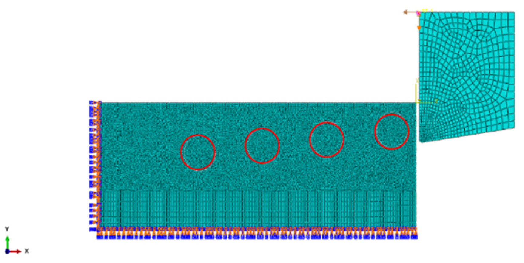
This study used ABAQUS finite element simulation software (Abaqus 2020, Dassault SIMULIA., Providence, RI, USA)to establish a two-dimensional thermodynamic coupled cutting model. A PCD tool (Jiaxing Worldia Diamond Tools Co., Ltd., Jiaxing, China) with excellent cutting performance [19] was used to simulate the cutting of a workpiece with TC4 titanium alloy as the substrate and TiC particles as the reinforcing particles. At the same time, in order to study the failure of particles at different positions during cutting, this simulation establishes four different position particle models, binding four reinforcing particles within the matrix, and the particle positions are shown in Figure 2.
To reduce analysis time, the workpiece mesh was partitioned. The mesh cell type was a four-node thermodynamically coupled plane strain quadrilateral reduced integral cell [20]. The vibration frequency of the tool during the simulation is f = 20 kHz, the amplitude A = 12.5 μm and B = 3 μm. The conventional cutting speed v = 30 m/min. The critical cutting speed is 1570 mm/s, which is greater than three times the cutting speed and is a detached cut [21]. The workpiece is completely fixed, and the predefined temperature field is 20°. A periodic simple harmonic vibration amplitude with initial velocity is applied in the X direction at the reference point of the tool to achieve a reciprocating feed vibration cut in the X direction, on top of which a periodic simple harmonic vibration amplitude in the Y direction is applied to achieve a double excitation vibration cut. The final simulation modeling is shown in Figure 3.
The TC4 matrix uses the classical Johnson-Cook plasticity ontological model [22], which is widely used in metal cutting simulations for large strain, elastic large deformation situations [23], with the following equations:
σ ˉ = ( A + B ε n ) [ 1 + C ln ( ε ˙ ε ˙ 0 ) ] [ 1 ( T T r o o m T m e l t T r o o m ) m ] ,
where: σ ˉ is the equivalent stress; ε ˙ 0 is the equivalent elastic strain; ε ˙ is the equivalent elastic strain rate; ε ˙ 0 is the reference equivalent elastic strain rate; T is the current temperature of the workpiece; T r o o m is the room temperature; T m e l t is the melting temperature; A is the yield stress; B is the hardening modulus; C, m, and n are the property factors, thermal softening factor, and work hardening index [24]. The J-C intrinsic model simulation parameters for the matrix material TC4 are shown in Table 1.
TiC reinforced particles in particle-reinforced titanium matrix composites are typically brittle and rigid materials, for which the brittle fracture criterion is usually chosen to describe the relationship between stress and strain in material deformation [25]. The stress–strain relationship can be described by Hooke’s law. The properties of TiC materials are shown in Table 2:
In this study, the J-C fracture failure criterion is used as the fracture failure criterion for TC4 and the cell damage can be defined as the following equation:
D = Δ ε ε f
where Δ ε is the change in equivalent plastic strain per period of integration; 𝜀𝑓 is a function of temperature, strain rate, equivalent force and pressure to represent the equivalent plastic strain at the onset of damage. D is the parameter that quantifies the damage to the unit, when D = 1 damage will occur, and the fracture strain can be calculated according to the following expression:
ε f = [ D 1 + D 2 exp ( D 3 σ * ) ] 1 + D 4 ln ( ε ˙ ε ˙ 0 ) [ 1 + D 5 ( T T room T melt T room ) ] ,
D1, D2, D3, D4, and D5 are the damage parameters for TC4 material, which can be obtained from material tests, as shown in Table 3:
Currently, the Coulomb friction model has been validated and widely used for the cutting simulation of metal matrix composites [26]. Therefore, in this paper, cutting simulation experiments will be carried out on the basis of this theory.
In this study, a two-dimensional orthogonal cutting model will be established to analyze and compare the changes in cutting force and cutting temperature and their characteristics during conventional cutting and elliptical ultrasonic vibration cutting under certain cutting parameters and certain vibration parameters. This is to analyze the breakage of TiC particles and the stress when the tool contacts the particles and to investigate their effects on the morphology of the machined surface.

4. Simulation Results and Analysis

4.1. Comparison of Surface Morphology

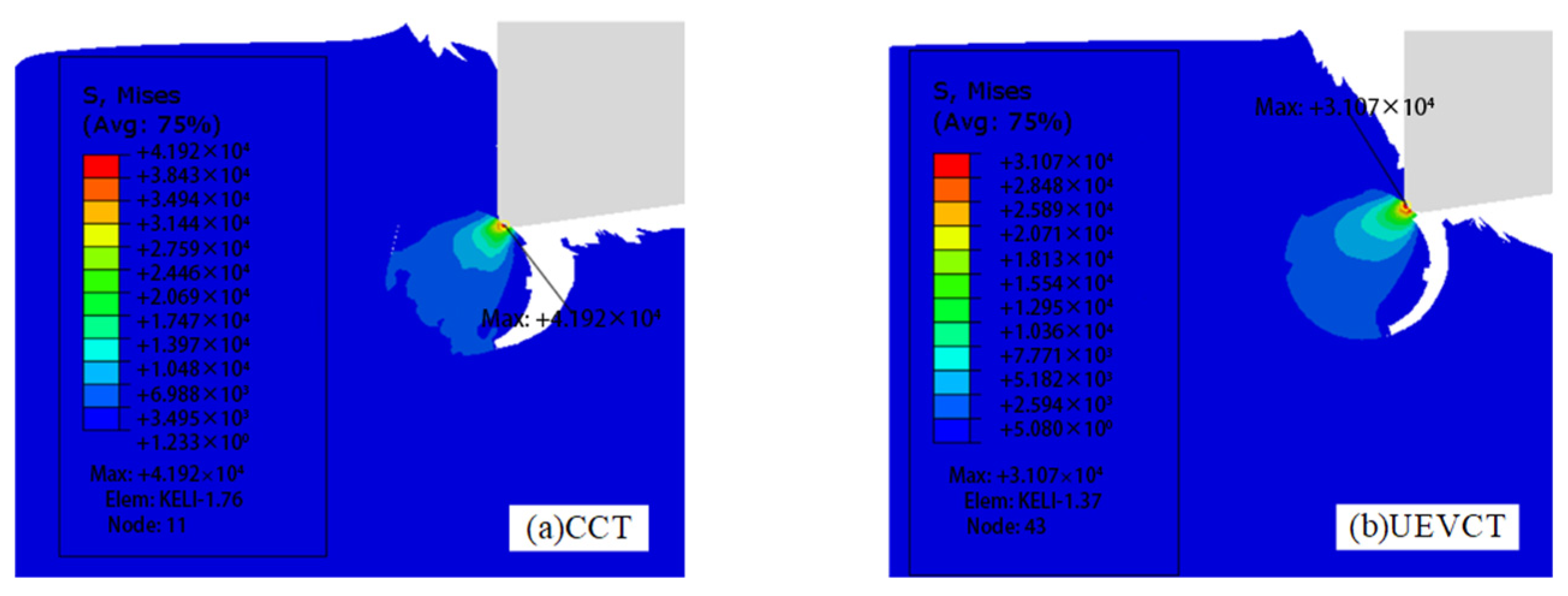
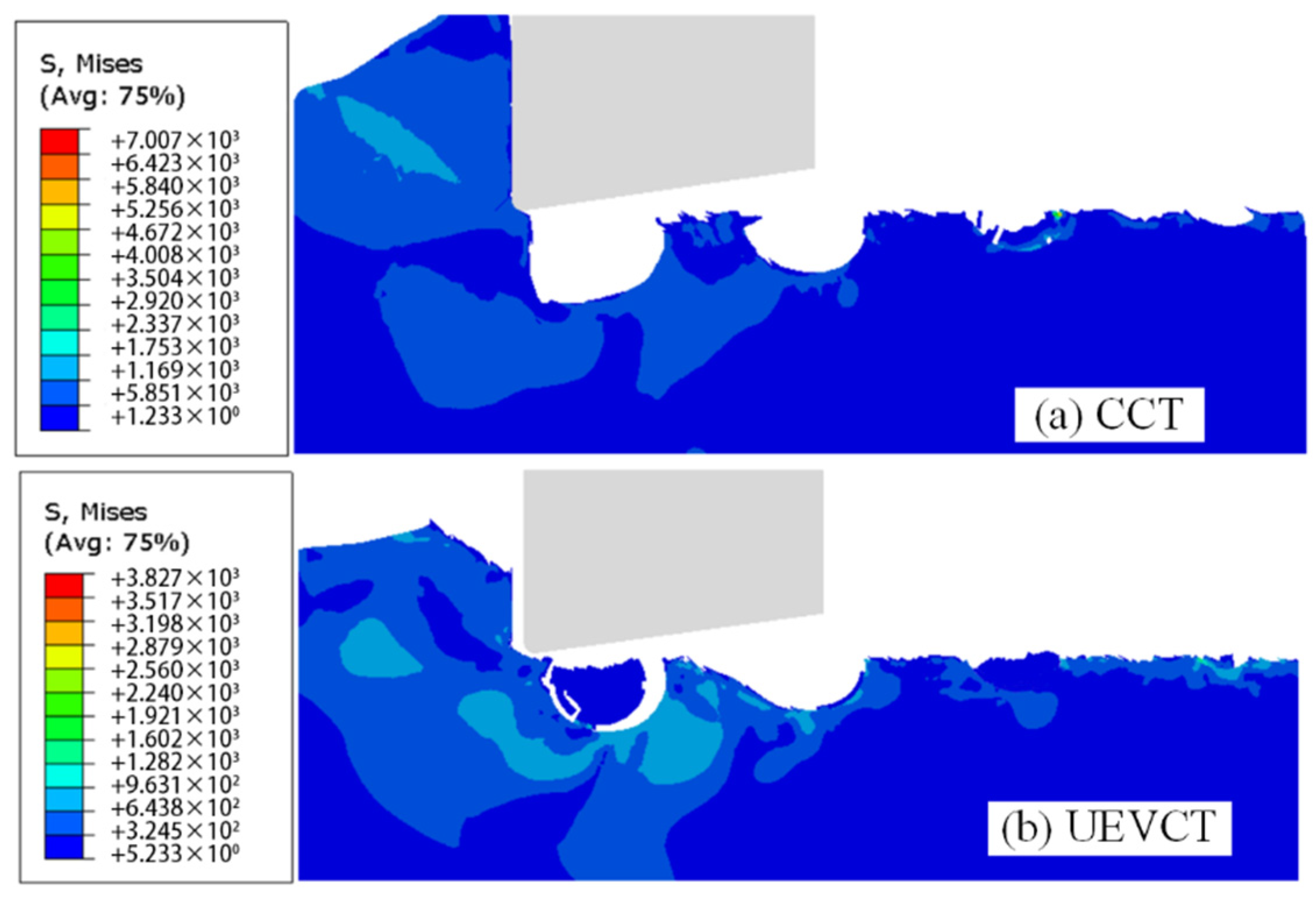
Figure 4 shows the comparison at the maximum stress during the cutting process. It is clear that the equivalent Mises stress of UEVCT is lower compared to CCT, which is conducive to the formation of a better surface; from the overall cutting process (Figure 5), the machined surface quality of UEVCT is significantly improved compared to CCT, and some of the TiC particles remaining within the substrate effectively reduce the machined surface roughness and inhibit the generation of burrs. According to the elliptical cutting characteristics, elliptical vibration cutting can be considered as variable speed cutting [27]. At the moment when the tool tip touches the substrate, the cutting speed is larger compared to CCT; this speed is the critical cutting speed, VC = 2πfA, and the larger the cutting speed, the smaller the cutting force, the smaller the material deformation caused, so UEVCT can relatively reduce the machined surface roughness.

4.2. Comparison of Cutting Forces

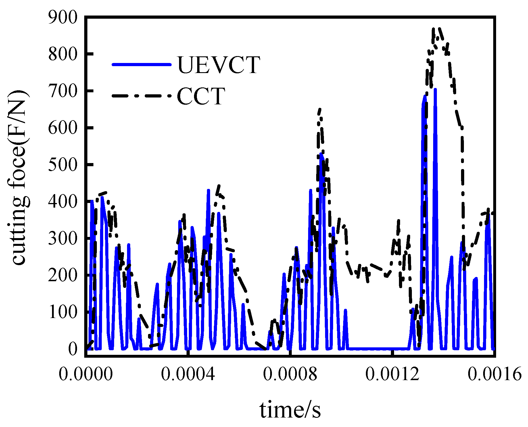
Figure 6 shows a comparison of UEVCT and CCT cutting forces at a cutting speed of 30 min/m and a vibration frequency of 20 kHz. UEVCT also has a significant periodicity of cutting forces due to its simple harmonic vibration cutting characteristics, while it can be seen from Figure 4 above that when the tool cuts particle 4, the stress concentration is most intense due to the strong squeezing of the particle by the tool as the particle is positioned downwards, resulting in a significant increase of cutting forces. The average cutting force for CCT was calculated to be 269.24 N and for UEVCT 107.61 N, a relative reduction of 60%. Due to the elliptical vibration cutting process, in the first-half period for the cutting phase the tool rake face and workpiece contact; for the second-half period for the separation phase, the retreat process tool and workpiece do not contact, thus resulting in the simulation of the cutting force’s output being zero; and, in 1.024 × 10⁻³ s to 1.264 × 10⁻³ s, due to the elliptical vibration variable speed cutting effect of chip fracture separation, the tool emptying away, the cutting force is nearly zero. The above causes a significant reduction in the average UEVCT cutting forces. Due to the elliptical vibration cutting process, in the first-half period for the cutting phase, the tool rake face and the workpiece contact each other; in the second-half period for the separation phase, for the retraction process of the tool, the tool and the workpiece do not contact at this time, thus resulting in the simulation cutting force’s output being zero; and in, 1.024 × 10⁻³ s to 1.264 × 10⁻³ s, due to the elliptical vibration variable speed cutting effect of chip fracture and separation, the tool emptying away. The above causes a significant reduction in the average UEVCT cutting force.

4.3. Comparison of Cutting Temperature

Figure 7 shows the cutting temperature variation curves of the tool tip for the two cutting methods under the same cutting parameters as above. The post-processing uses a point at the rounded corner of the tool tip as the temperature output point to simulate the tool tip temperature variation. Particle 4 rotates under the force of the tool and the heat generated by the intense friction with the substrate and tool causes the tool tip temperature to rise sharply, reaching a peak temperature, which decreases as particle 4 is removed. It is calculated that the average temperature of CCT is 115.7° and the average cutting temperature of UEVCT is 95.3°, a relative reduction of 17.6%. When ultrasonic vibration cutting is adopted, because the rake face of elliptical vibration cutting is separated from the workpiece, the temperature decreases during the separation process, while in traditional cutting, the rake face of the tool is always in contact with the matrix, making the average temperature of the ultrasonic vibration cutting lower than that of traditional cutting, and effectively avoiding the temperature accumulation during the cutting process. The peak temperature of ultrasonic vibration cutting is significantly lower than that of traditional cutting.

4.4. Comparison of Particle Crushing to Remove Processing Defects

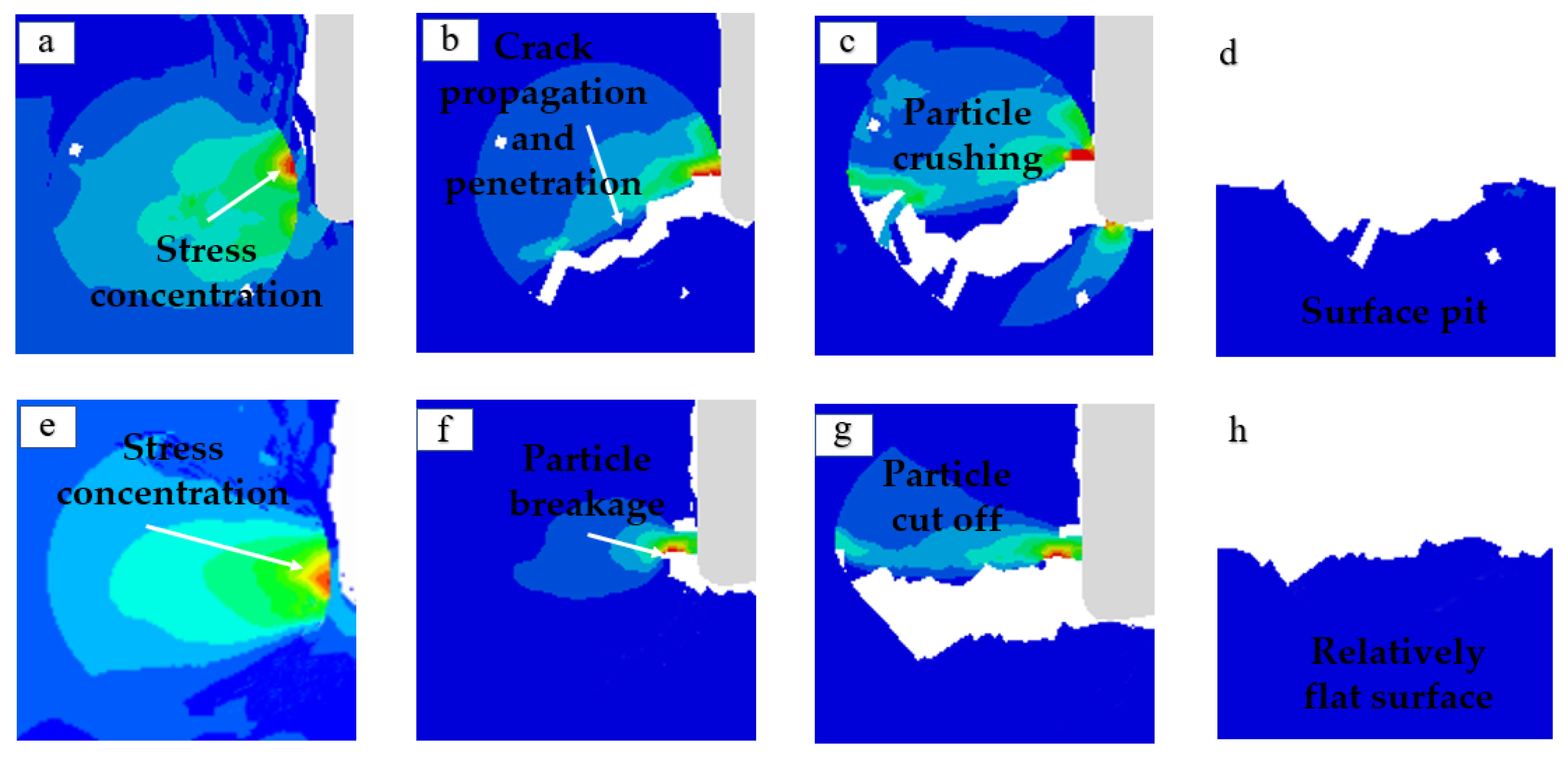
The main defect formed on the processing surface of TiC particle reinforced titanium matrix composites is the pit formed from particle breaking and debonding, which is mainly manifested as particle breaking. The following is a comparative analysis of particle breaking when cutting TiC particles with two cutting methods at the same time: Figure 8 shows the simulation of the failure removal process of TiC particle 1. The cutting process of CCT is relatively gentle; stress concentration occurs inside the particle as the tool advances, followed by interfacial damage at the two-phase interface of the particle matrix [28], TiC particle, matrix two-phase boundary failure, and the formation of interfacial debonding phenomena as in Figure 8b. The left side of the particles sprouted a micro-crack as in Figure 8c. Due to the particle location being relatively high, the crack has not continued to expand as the particle debonding was pulled out. On the contrary, with elliptical vibration cutting: in the cutting feed stage, due to the high instantaneous cutting speed, the rake face impacts the substrate and the stress transfer leads to the first interfacial damage at the two-phase interface of the particle substrate as shown in Figure 8e, followed by the next elliptical period TiC particles not continuing to fail along the two-phase interface under the impact of the tool but cracking at the bottom. In the subsequent elliptical vibration cutting process, the removal of particles is relatively complete under the ironing of the flank tool face.
Figure 9 shows the simulation of the TiC particle 2 failure removal process. In the conventional cutting process, due to the uniform feed of the tool, there is no variable speed cutting, so the TiC particles sprout cracks after the stress concentration and quickly penetrate the whole particles under the effect of the continuous feed and pushing of the tool as shown in Figure 9b, resulting in particle fragmentation. Finally, the upper of particles are removed with the chips and the particles remaining in the substrate form small craters as shown in Figure 9d. During the UEVCT process, as shown in Figure 9e, the TiC particles are subjected to stress concentration by the tool; as the tool advances further, the particles reach the stress limit and start to break, as shown in Figure 9f; at this point, the tool completes an elliptical period of motion and starts to rise, and in the next elliptical vibration period as shown in Figure 9g, the TiC particles are cut off by the impact of the tool during the tool feed stage, and the TiC particles have a flatter fracture.
Figure 10 shows the simulation of the TiC particle 4 failure removal process. In the conventional cutting process, due to the TiC particle position relative to the cutter point downward, the TiC particles are subjected to stress concentration. Then, the interface damage occurs under the continuous feed of the tool as shown in Figure 10b, and the tool drives the particles to rotate counterclockwise within the matrix, resulting in further expansion of the interface damage as shown in Figure 10c. Finally, the TiC particles are unable to carry the tool pressure to decouple and fly out, and the matrix forms irregular large craters as shown in Figure 10d. In the UEVCT process, under the impact of the tool, small interfacial damage appears when the TiC particles start to contact the tool as shown in Figure 10f. During the next elliptical period of cutting, the interfacial damage also appears on the upper left side of the particles as shown in Figure 10g due to the change in cutting force direction, and the upper part of the particles is rapidly cut off under the impact cutting force of the tool in the next elliptical cutting period immediately afterwards. The two-phase interface is also severely damaged, but the surface quality is improved compared with the conventional cutting method.

4.5. Comparison of Cutting Temperature

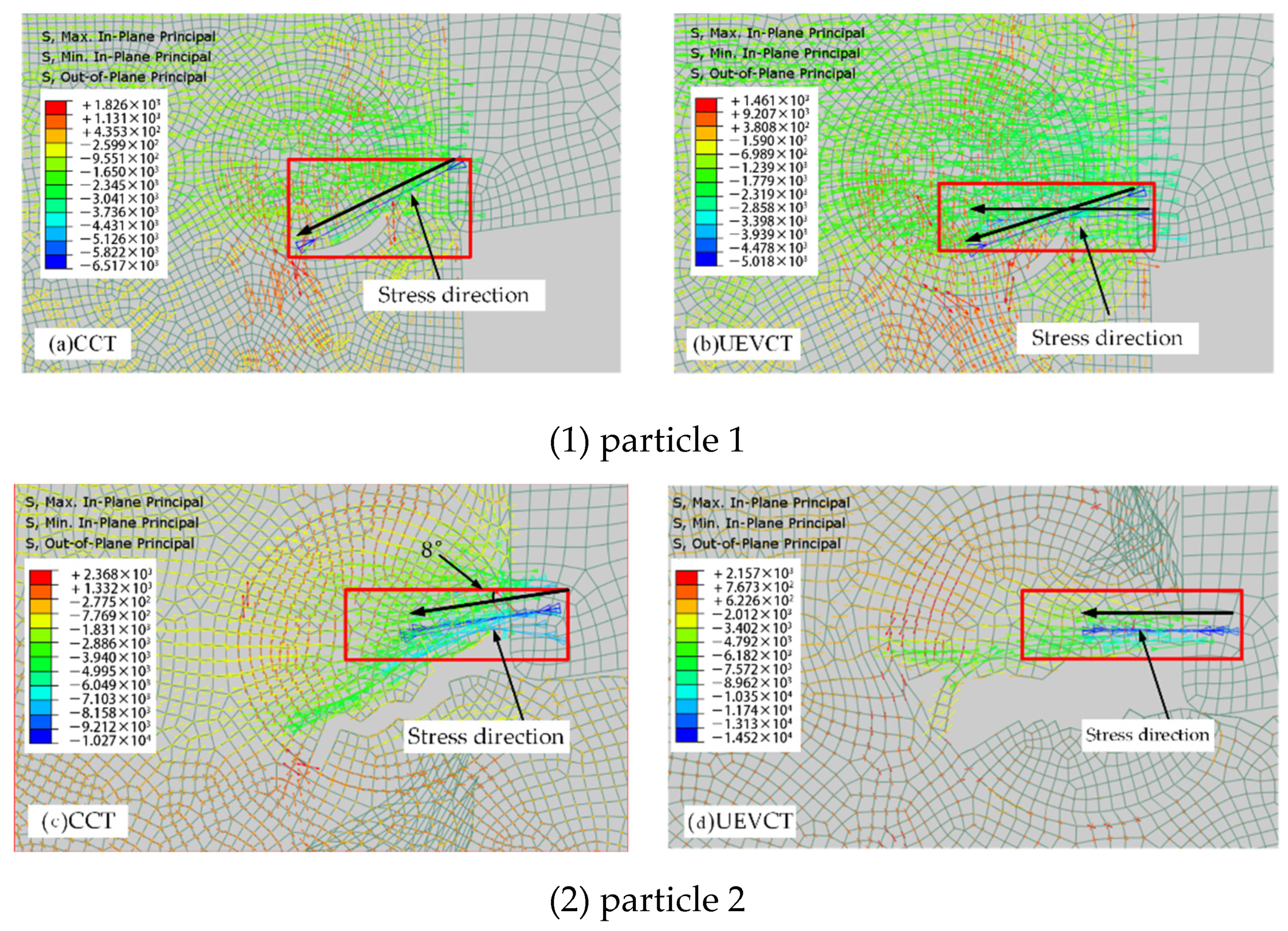
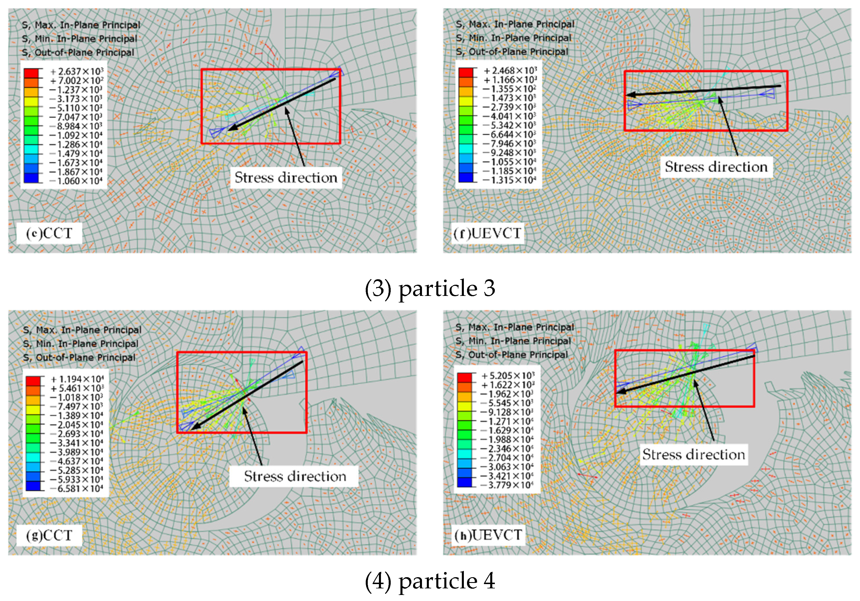
Figure 11 shows the stress distribution of TiC particles under the action of two cutting methods: the traditional cutting method and elliptical vibration cutting method, the compressive stress direction of particle 1 at the beginning of the CCT method has a certain angle with the horizontal direction, while the UEVCT method also has a horizontal force that is beneficial to particle removal when cutting particles; the stress contrast of particle 2 is more obvious, the UEVCT method only has a horizontal compressive stress at this time, and particle 2 is cut off; the situation of particle 3 is the same as particle 2.
As for the particle, due to the mostly downward position, the inclination angle of the stress direction during UEVCT cutting is smaller than CCT. The above analysis of the instantaneous stress direction of the four particles can again show that the direction of force on the particle during elliptical vibration cutting tends to the horizontal direction which is favorable to particle removal.
Figure 12 shows the stress distribution and evolution of the crush removal process of TiC particle 4 in the CCT process, with the backward arrow indicating that the stress suffered is compressive stress and the opposite arrow indicating that the stress suffered is tensile stress. As the position of this particle is below the cutter point, the TiC particles mainly exist as downward extrusions under the advance of the tool, and as the tool advances, the interface between the TiC particles and the substrate fails and rotates counterclockwise in the substrate. The stress at the contact point between the cutter point and the TiC particles is the largest and is mainly compressive stress at the moment of Figure 12c. Finally, the particles reach the yield limit and are crushed, and the crushing leads to the stress being transferred to the substrate, forming large irregular craters and seriously damaging the integrity of the machined surface.
Figure 13 shows the stress distribution and evolution of the cut-off removal process of TiC particle 4 in the UEVCT process at the same moment, while Figure 13a shows that the stress distribution of particles under the action of different cutting methods is different. Under the tool elliptical vibration method, the force on TiC particles is mainly the compressive stress in the horizontal direction, as shown in Figure 13c. The tool is located at the end of cutting moment position b in Figure 1 and the force between the tool and the particles is the largest in this period, followed by the next elliptical vibration cutting period, i.e., Figure 13d, when the transient cutting force is larger due to the elliptical vibration cutting variable speed, thus meaning that the TiC particles cannot be carried and are cut off and removed.

5. Conclusions

  • Ultrasonic elliptical vibration cutting has a significant reduction in average cutting forces due to the periodic nature of the cutting. This is a result of the variable speed cutting action, with a 60% reduction in average cutting forces compared to conventional cutting;
  • Ultrasonic elliptical vibration cutting briefly separates the tool from the chip during the rewind phase of each cutting period, during which the tool is cooled, resulting in a periodic wave-like rise in the temperature profile and a 17.6% reduction in the average cutting temperature compared to conventional cutting methods;
  • By analyzing the stresses between the tool and the particles during co-located particle cutting, ultrasonic elliptical vibration cutting tends to have a horizontal direction of particle fragmentation and cracking, where the TiC particles are mainly removed by cutting off.
Cutting simulations were studied using a simplified model. The errors of cutting force and cutting temperature obtained from the research results are within 15%. However, in a word, this study provides a reference for the elliptical ultrasonic vibration cutting simulation of PTMC materials and provides a theoretical basis for future experiments that can be conducted to measure and compare surface roughness values with the experimental results. A cutting model that is more in line with the actual situation can be established later to study the changes of cutting force, cutting temperature, and stress as well as particle fragmentation more accurately, to the point where the error can be controlled to within 10%.

Author Contributions

Conceptualization, H.H. and W.X.; methodology, K.Z.; software, W.X.; validation, H.H., W.X.; formal analysis, W.X.; investigation, C.Z.; resources, H.H.; data curation, W.X.; writing—original draft preparation, W.X.; writing—review and editing, W.X.; visualization, W.X.; supervision, J.P.; project administration, H.H.; funding acquisition, B.Z. and H.H. All authors have read and agreed to the published version of the manuscript.

Funding

National Natural Science Foundation of China (52205475) and Six talent peaks project in Jiangsu Province (GDZB-064).

Data Availability Statement

All data included in this study are available from the corresponding author on reasonable request.

Conflicts of Interest

The authors declare no conflict of interest.

References

  1. Maciej, M. Titanium Alloys and Titanium-Based Matrix Composites. Metals 2021, 11, 1463. [Google Scholar]
  2. Jung, H.-D. Titanium and Its Alloys for Biomedical Applications. Metals 2021, 11, 1945. [Google Scholar] [CrossRef]
  3. Tan, R.; Zhao, X.; Sun, T.; Zou, X.; Hu, Z. Experimental Investigation on Micro-Groove Manufacturing of Ti-6Al-4V Alloy by Using Ultrasonic Elliptical Vibration Assisted Cutting. Materials 2019, 12, 3086. [Google Scholar] [CrossRef] [Green Version]
  4. Han, Y.; Sun, X.; Qiu, P.; Mao, J.; Zhang, D. Research and progress of advanced processing technology for particle reinforced titanium matrix composites. J. Compos. Mater. 2017, 34, 1625–1635. [Google Scholar] [CrossRef]
  5. Wang, M.; Li, S.; Zheng, Y.; Li, X. Effect of ultrasonic vibration milling parameters on cutting forces. China Mech. Eng. 2014, 25, 2024–2029. [Google Scholar]
  6. Ji, Y.; Li, X.; Zhang, D.Y. Ultrasonic elliptical vibration precision cutting. Aviat. Manuf. Technol. 2005, 4, 92–95. [Google Scholar]
  7. Tan, R. Fundamental Research on Ultrasonic Elliptical Vibration Assisted Ultra-Precision Cutting of Titanium Alloy. Ph.D. Thesis, Harbin Institute of Technology, Harbin, China, 2020. [Google Scholar]
  8. Muhammad, R.; Ahmed, N.; Demiral, M.; Roy, A.; Silberschmidt, V.V. Computational Study of Ultrasonically-Assisted Turning of Ti Alloys. Adv. Mater. Res. 2011, 223, 30–36. [Google Scholar] [CrossRef] [Green Version]
  9. Dong, T.; Zhang, M.; Li, Y.; Chen, J.; Liu, X. Numerical study on ultrasonic elliptical vibration cutting of aviation aluminum alloy. Light Ind. Mach. 2021, 39, 48–55. [Google Scholar]
  10. Tan, R.; Zhao, X.; Guo, S.; Zou, X.; He, Y.; Geng, Y.; Hu, Z.; Sun, T. Sustainable production of dry-ultra-precision machining of Ti–6Al–4V alloy using PCD tool under ultrasonic elliptical vibration-assisted cutting. J. Clean. Prod. 2020, 248, 119254. [Google Scholar] [CrossRef]
  11. Teng, J.; Feng, Z.; Jiao, F.; Zhao, B. Tool Wear in Longitudinal-Torsional Ultrasonic Vibration Milling of Titanium Alloys. Surf. Technol. 2019, 48, 297–303. [Google Scholar]
  12. Zhang, P.; Zhang, X.; Cao, X.; Yu, X.; Wang, Y. Analysis on the tool wear behavior of 7050-T7451 aluminum alloy under ultrasonic elliptical vibration cutting. Wear 2021, 466–467, 203538. [Google Scholar] [CrossRef]
  13. Usman, M.M.; Zou, P.; Ji, B.; Lin, T. Development of empirical models for the prediction of surface functional parameters in ultrasonic elliptical vibration cutting. Int. J. Adv. Manuf. Technol. 2021, 113, 2575–2594. [Google Scholar] [CrossRef]
  14. Teng, L.; Xiang, J.; Tao, W.; Wang, B.; Xie, L. Review upon Simulation of Cutting Process of Particulate Reinforced Metal Matrix Composites. Technology 2019, 53, 3–9. [Google Scholar]
  15. Jiang, Y.; Pi, J.; Yang, G.; Jiang, T.; Shen, Z. Effect of ultrasonic elliptical vibration cutting trajectory on surface morphology. J. Ordnance Eng. 2019, 40, 2170–2176. [Google Scholar]
  16. Chen, W.; Zhang, X. Investigation on the cutting mechanism of SiCp/Al composites in ultrasonic elliptical vibration machining. Int. J. Adv. Manuf. Technol. 2022, 120, 4707–4722. [Google Scholar] [CrossRef]
  17. Dai, C.; Yin, Z.; Zhao, M.; Cao, Z.; Li, H. Effect of Tilt Angle and Speed Ratio on Workpiece Micro Morphology in Ultrasonic Elliptical Vibration Cutting. Tool Technol. 2021, 55, 34–38. [Google Scholar]
  18. Tong, J.; Wei, G. Characterization of cutting forces in ultrasonic elliptical vibration cutting of titanium alloy. Vib. Impact 2019, 38, 208–215. [Google Scholar]
  19. Huan, H.; Xu, J.; Su, H.; Huo, F. Study on tool wear of PCD tool in turning titanium matrix composites. China Mech. Eng. 2016, 27, 1877–1883. [Google Scholar]
  20. Fathipour, M.; Hamedi, M.; Yousefi, R. Numerical and experimental analysis of machining of Al (20 vol% SiC) composite by the use of ABAQUS software. Mater. Werkst. 2013, 44, 14–20. [Google Scholar] [CrossRef]
  21. Li, S.; Han, J.; Yu, H.; Wang, J.; Lu, M.; Tian, Z.; Lin, J. Finite Element Investigation on Cutting Force and Residual Stress in 3D Elliptical Vibration Cutting Ti6Al4V. Micromachines 2022, 13, 1278. [Google Scholar] [CrossRef]
  22. Pantalé, O.; Bacaria, J.L.; Dalverny, O.; Rakotomalala, R.; Caperaa, S. 2D and 3D numerical models of metal cutting with damage effects. Comput. Methods Appl. Mech. Eng. 2004, 193, 4383–4399. [Google Scholar] [CrossRef] [Green Version]
  23. Mebrahitom, A.; Choon, W.; Azhari, A. Side Milling Machining Simulation Using Finite Element Analysis: Prediction of Cutting Forces. Mater. Today Proc. 2017, 4 Pt D, 5215–5221. [Google Scholar] [CrossRef]
  24. Xiang, D.; Shi, Z.; Feng, H.; Wu, B.; Zhang, Z.; Chen, Y.; Niu, X.; Zhao, B. Finite element analysis of ultrasonic assisted milling of SiCp/Al composites. Int. J. Adv. Manuf. Technol. 2019, 105, 3477–3488. [Google Scholar] [CrossRef]
  25. Ghandehariun, A.; Nazzal, M.; Kishawy, H.A.; Umer, U. On modeling the deformations and tool-workpiece interactions during machining metal matrix composites. Int. J. Adv. Manuf. Technol. 2017, 91, 1507–1516. [Google Scholar] [CrossRef]
  26. Chen, G.; Ren, C.; Zhang, P.; Cui, K.; Li, Y. Measurement and finite element simulation of micro-cutting temperatures of tool tip and workpiece. Int. J. Mach. Tools Manuf. 2013, 75, 16–26. [Google Scholar] [CrossRef]
  27. Han, X.; Zhang, D. Effects of separating characteristics in ultrasonic elliptical vibration-assisted milling on cutting force, chip, and surface morphologies. Int. J. Adv. Manuf. Technol. 2020, 108, 3075–3084. [Google Scholar] [CrossRef]
  28. Zheng, W.; Qu, D.; Qiao, G. Multi-phase modeling of SiC particle removal mechanism in ultrasonic vibration–assisted scratching of SiCp/Al composites. Int. J. Adv. Manuf. Technol. 2021, 113, 535–551. [Google Scholar] [CrossRef]
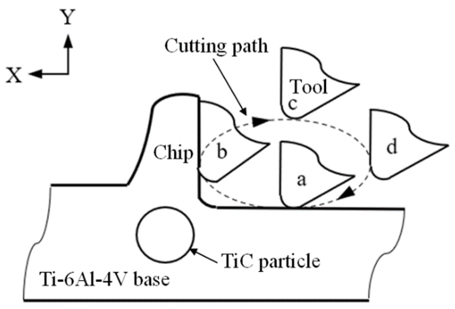
Figure 1. Schematic diagram of elliptical vibration cutting principle.
Metals 12 01769 g001
Figure 2. The relative position between particles and the overall cutting path of the tool.
Metals 12 01769 g002
Figure 3. Cutting finite element model and load diagram. The left side and the bottom are fixed signs. The red circle represents the position of particles.
Metals 12 01769 g003
Figure 4. Comparison of maximum equivalent stress. (a) Maximum stress point during conventional cutting; (b) Maximum stress point during ultrasonic elliptical vibration cutting.
Metals 12 01769 g004
Figure 5. Comparison of overall surface morphology in cutting process. (a) Conventional cutting shape; (b) Ultrasonic elliptical vibration cutting shape.
Metals 12 01769 g005
Figure 6. Comparison curve of cutting force.
Metals 12 01769 g006
Figure 7. Comparison curve of cutting temperature.
Metals 12 01769 g007
Figure 8. Simulation of TiC particle 1 failure removal process. (ad) CCT. (eh) UCT. Different colors represent the stress distribution, the brighter the color the more intense the stress concentration.
Metals 12 01769 g008
Figure 9. Simulation of TiC particle 2 failure removal process. (ad) CCT. (eh) UCT. Different colors represent the stress distribution, the brighter the color the more intense the stress concentration.
Metals 12 01769 g009
Figure 10. Simulation of TiC particle 4 failure removal process. (ad) CCT. (eh) UCT. Different colors represent the stress distribution, the brighter the color the more intense the stress concentration.
Metals 12 01769 g010
Figure 11. Force analysis of particles under two cutting modes. As shown in the picture, (a,c,e,g) is the stress direction of the particle during conventional cutting.(b,d,f,h) is the stress direction of the particle during ultrasonic elliptical vibration cutting.
Metals 12 01769 g011aMetals 12 01769 g011b
Figure 12. Stress evolution of CCT particle removal process. (ad) is the stress of the particle at different moments during CCT.
Metals 12 01769 g012
Figure 13. Stress evolution of UEVCT particle removal process. (ad) is the stress of the particle at different moments during UEVCT.
Metals 12 01769 g013
Table 1. J-C plastic constitutive parameters of TC4 material.
A/MPaB/MPaCnm T m e l t /°C T room /°C
8757930.010.3860.71156020
Table 2. Property parameters of TiC material.
CategoryValue
Density ρ (kg/m3)4930
Poisson’s ratio0.2
E (G Pa)500
Hardness (G Pa)31.4
Hard fracture toughness (MPa·m1/2)3.8
Table 3. J-C damage model parameters.
D1D2D3D4D5
−0.090.27−0.480.0143.87
Publisher’s Note: MDPI stays neutral with regard to jurisdictional claims in published maps and institutional affiliations.