Article

Long-Term Behavior of Clinched Electrical Contacts

1
Institute of Manufacturing Science and Engineering, Technische Universität Dresden, Helmholtzstraße 10, 01069 Dresden, Germany
2
TOX Pressotechnik GmbH & Co., KG, Riedstraße 4, 88250 Weingarten, Germany
3
Institute of Electrical Power Systems and High Voltage Engineering, Technische Universität Dresden, Helmholtzstraße 10, 01069 Dresden, Germany
*
Author to whom correspondence should be addressed.
Metals 2022, 12(10), 1651; https://doi.org/10.3390/met12101651
Submission received: 26 August 2022 / Revised: 15 September 2022 / Accepted: 25 September 2022 / Published: 30 September 2022
(This article belongs to the Special Issue Advances in Mechanical Joining Technologies)

Abstract

:
Joining by forming operations presents powerful and complex joining techniques. Clinching is a well-known joining process for use in sheet metalworking. Currently, clinched joints are focusing on mechanically enhanced connections. Additionally, the demand for integrating electrical requirements to transmit electrical currents will be increased in the future. This integration is particularly important, for instance, in the e-mobility sector. It enables connecting battery cells with electrical joints of aluminum and copper. Systematic use of the process-specific advantages of this joining method opens up the possibility to find and create electrically optimized connections. The optimization for the transmission of electrical currents will be demonstrated for clinched joints by adapting the tool geometry and the clinched joint design. Based on a comparison of the electrical joint resistance, the limit use temperature is defined for the joining materials used based on the microstructural condition and the aging condition due to artificial aging. As a result of the investigations carried out, reliable current transmission at a constant conductor temperature of up to 120 °C can be achieved for clinched copper–copper joints. In the case of pure aluminum joints and mixed joints of aluminum and copper, long-term stable current transmission can be ensured up to a conductor temperature of 100 °C.

1. Introduction

The technical task of joining materials in a way that is capable of carrying current is arising in many areas of industrial production in the context of the energy transition and the electrification of private transport. Combinations of a wide variety of materials, e.g., the combination of copper with aluminum (Figure 1), are becoming increasingly important.
The successful use of material combinations depends, to a large extent, on the joining technology, and comprehensive knowledge of the joining compounds and their behavior in the electrical circuit is of decisive importance. Sheet metals with variable thickness and a variable type of material can be joined by clinching.
By using clinching, the weight is not increased because neither filler material nor auxiliary joining elements are necessary [1]. For this reason and due to the low energy demand during the process, costs are exceptionally low. In many applications, concerning the mechanical properties, the use of clinching is state-of-the-art, especially in automobile manufacturing [2].
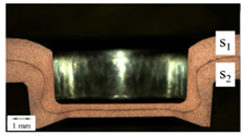
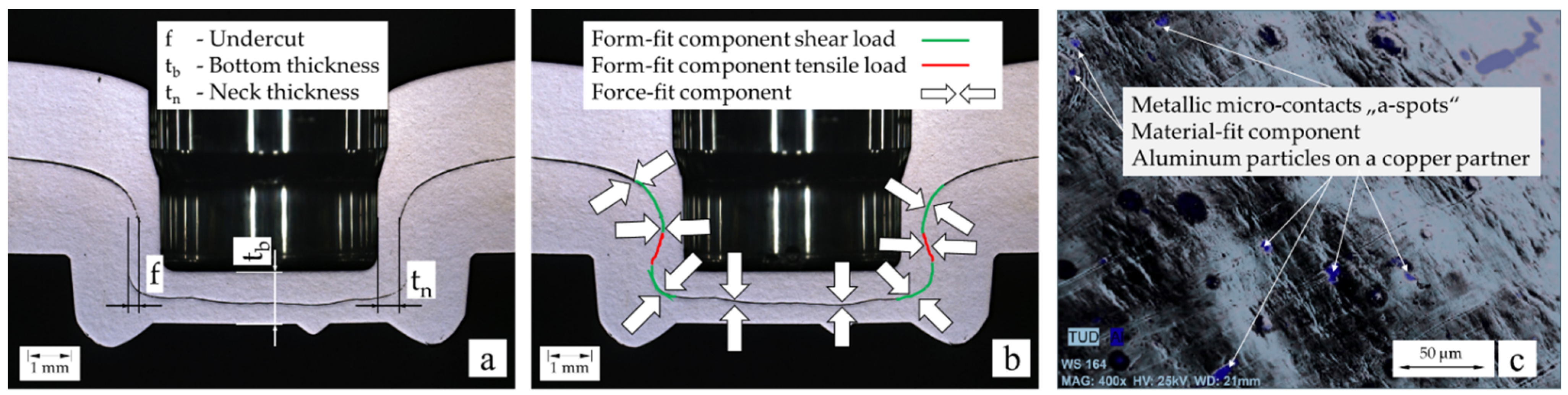
Joining by clinching produces a joint that can be characterized by the binding mechanisms form-, force-, and material-fit. The form-fit component of a clinched joint is determined by the clinching tools (punch and die) and the materials to be joined (mechanical properties and thickness). The force-fit component is determined by the spring back effect after the removal of the joining tools. An existing material-fit component can be generated by the material properties of the joining partners and the joining parameters such as penetration depth and process force. Regarding the mechanical requirements of the clinched joint, the characteristic parameters (Figure 2a) such as neck thickness (tn) and undercut (f) are used for the design of clinched joints as a function of the bottom thickness (tb). The geometrical parameters of this joint can characterize the binding mechanism form-fit of a clinched joint as a function of the main mechanical load direction (Figure 2b). However, the geometric parameters are not suitable for designing a clinch joint in terms of electrical conductivity. For a long-term stable transmission of electrical currents, the force-fit component, and a possible material-fit component, which can occur under certain conditions, here using the example of a mixed joint of aluminum and copper in the neck area (Figure 2c), are more important.
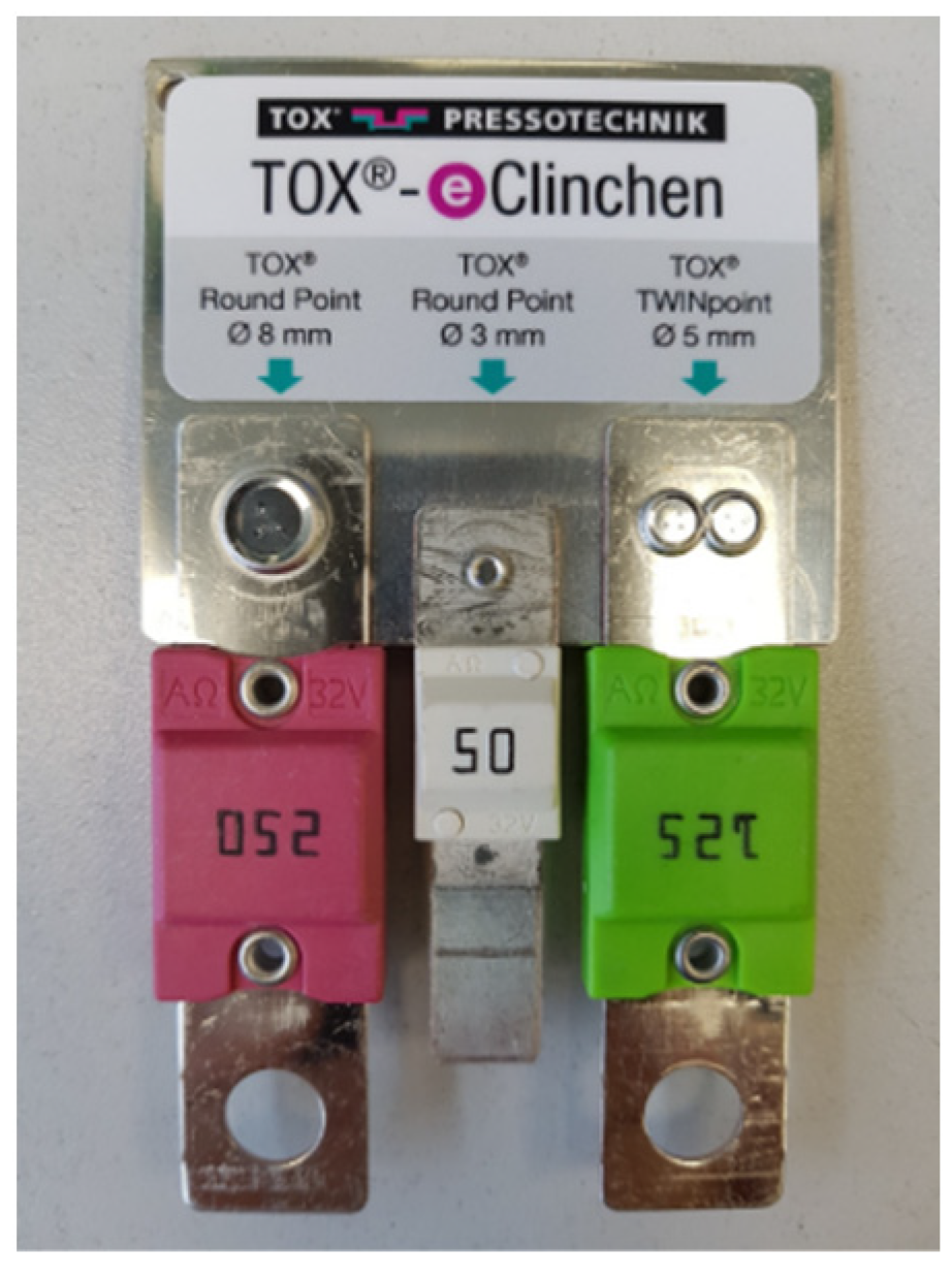
A foreseeable demand seems to be the function of electrical contact in joining technologies because of many advantages (e.g., no heat input) and the trend toward increasing electrification of automobiles, as referenced in [3], or battery packs according to [4]. Another application in the field of electromobility is the clinching of fuses with bus bars (Figure 3).
The trend towards electro-mobility, especially against the backdrop of mixed material joints (e.g., Al-Cu), emphasizes the necessity of such a functional integration. The joint design needs to be extended by the electrical properties for the functional integration of a long-term stable and safe electricity transmission [5]. The result is an expanded, multi-functional range of applications. In electrical operation, the clinched joint represents a closed contact [6]. Electrical contact is defined as the current-carrying contact between two conductive materials [7]. The aim is to transmit the electrical current as loss-free as possible via the joint by point, line, or surface contacts. The total area in the overlap region between the contact pieces is the apparent contact area As [8]. However, electric current cannot be transmitted over the entire apparent contact area [8]. There are insulating impurity layers on the surfaces of the contact pieces that can make contact difficult [9]. These are, for example, oxide layers and layers of oil, grease, and dust that occur due to handling and storage. Impurity layers can be influenced by mechanical and chemical cleaning, but in the case of aluminum, for example, a new oxide layer forms immediately. The contact pieces do not have a flat surface, i.e., there is always a microscopic rough surface. The contact pieces initially touch each other only at the roughness peaks. With sufficiently high contact force, thin impurity layers can be cracked and displaced at the roughness peaks, so that microscopic metallic contacts, also named a-spots, are formed. In adjacent areas, only very thin impurity layers remain. For app. 1.5 nm thick impurity layers, electrons can “tunnel” through these layers. These quasi-metallic contact areas Aqm have a higher resistance Rqm than the a-spot resistance. At the contact area, the current constricts to a relatively small cross-section compared to the prospective conductor. The constriction of the current lines to a smaller cross-section is equivalent to a higher resistance, which is called constriction resistance Re.
According to [6], the constriction resistance can be calculated as follows (Equation (1)):
R e = ρ π 4 · H F C
The constriction resistance depends on the resistivity ρ, the contact hardness H of the contact material, and the contact force FC, which presses the two contact pieces against each other and indicates, hereby, the force-fit component. The determined resistance is referred to as the joint resistance RJ (Equation (2)). The joint resistance is composed [10] of the intrinsic resistance Rb, the constriction resistance Re and the resistance of existing impurity layers Rf.
RJ = Re + Rf + Rb
For the application of these calculations to clinched joints, the knowledge of contact force (a force-fit component of the clinched joint) and the surface condition of the contact pieces is necessary. The first quantitative detection of the force-fit component was conducted in [11] by a torsion test and a Finite Elements Simulation in [12] by calculating the contact normal force between the joining partners. Since different materials have different intrinsic resistivities, it is expedient not to assess the conductivity of a joint solely based on the electrical resistance. The performance factor ku (Equation (3)) is introduced to evaluate the electrical quality [10].
k u = R J R L = R J R L 1 + R L 2 2
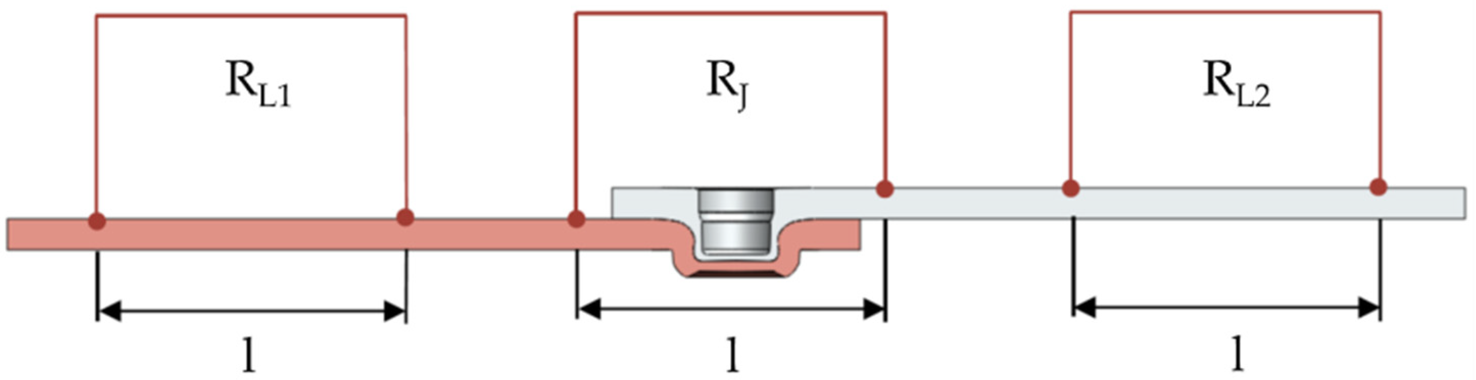
For mixed material joints, joints of two different materials, the conductor resistance RL results from the mean value of the material resistances RL1 and RL2, measured over the measuring length l (Figure 4). This allows samples made of different materials and joining systems to be compared in terms of their interconnect resistance. The performance factor ku represents the ratio of the joint resistance RJ, measured over the joint length, to the average resistance of the contact partners RL1 and RL2 of the same measuring length (Figure 4).
A performance factor ku = 1 indicates that when the joint is energized, no higher power loss occurs than in the rest of the conductor. Since the conductor cross-section increases in the area of the connection due to the overlapping of the conductors, performance factors of ku < 1 can occur with very well-contacted joints. To be able to evaluate the value of the performance factor, a thermal model of the joint was created using the heat network method, and the temperature-equivalent performance factor k
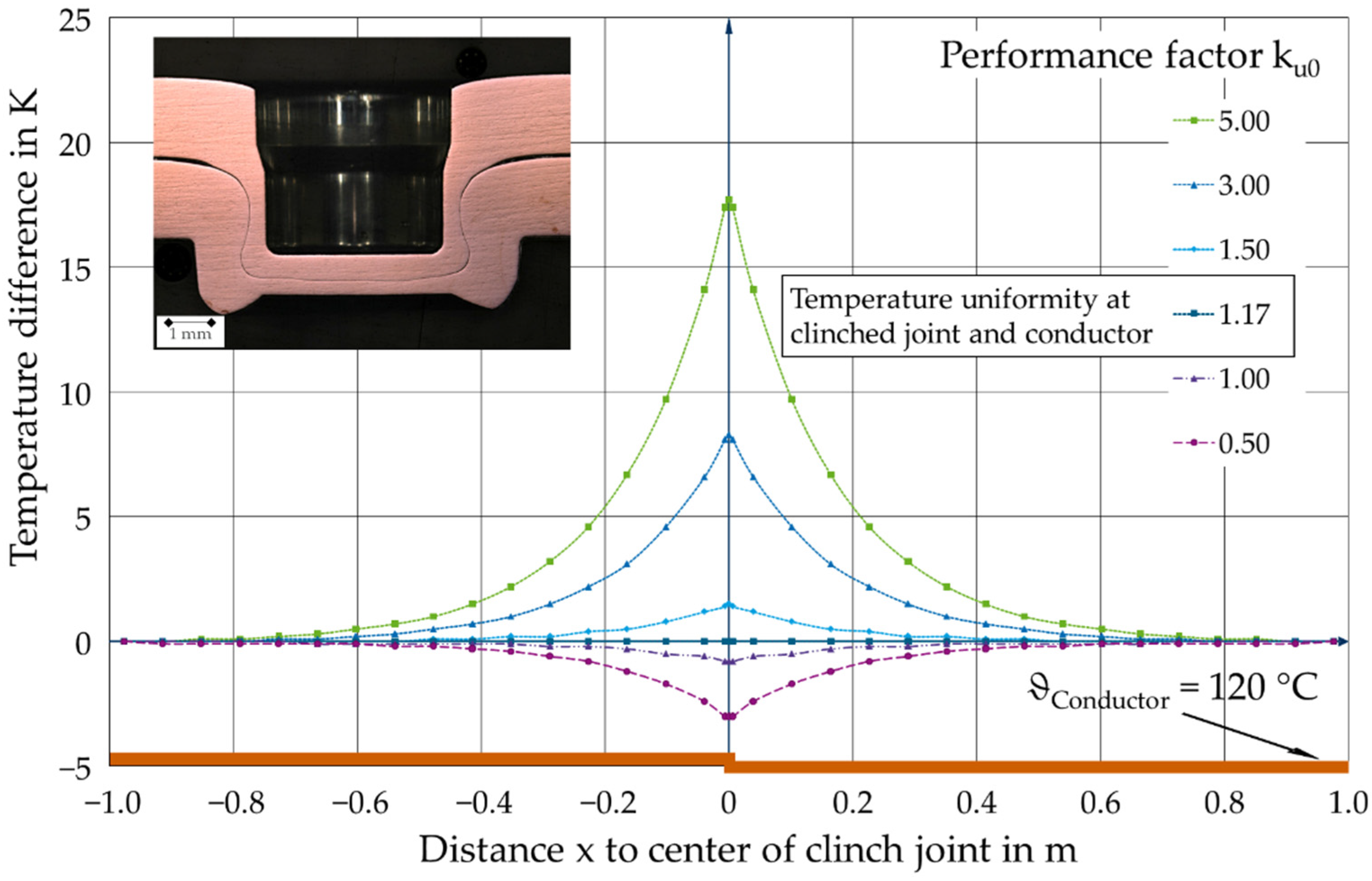
uT-20 was calculated. The temperature-equivalent performance factor describes the value at which joint and connected conductors have the same temperature. The heat network method uses the analogy between electrical and thermal networks. The heat sources describe the current heat losses in the joint and the connected conductors; resistances describe the heat transfer by convection, radiation, and conduction to the environment or into adjacent volume elements of components. Calculating the heating at specific locations can only be performed iteratively due to the temperature dependence of the heat transfer parameters. Therefore, in [5], the heat networks were created and calculated using the program Orcad-Capture/PSpice. The temperature of the joints was calculated as a function of the performance factor or the joint resistance and the temperature of the connected conductor (Figure 5).
The test current Itest, introduced during the tests on the current-carrying conductor, led to a temperature difference between a conductor and joint (hot or cold) depending on the joint resistance RJ. If the temperature of the joint is lower than that of the reference conductor, a requirement for long-term stable operation is given. If an excess temperature occurs θe ≥ θlimit in the joint, the joint resistance may increase due to strong force reduction and subsequent oxidation. From the results, it was possible to determine the excess temperature of the connection compared to the connected conductor (Figure 5). It can be seen that a performance factor lower than ku0 < 1.17 leads to the same temperature at the joint as the conductors. From a performance factor greater than k
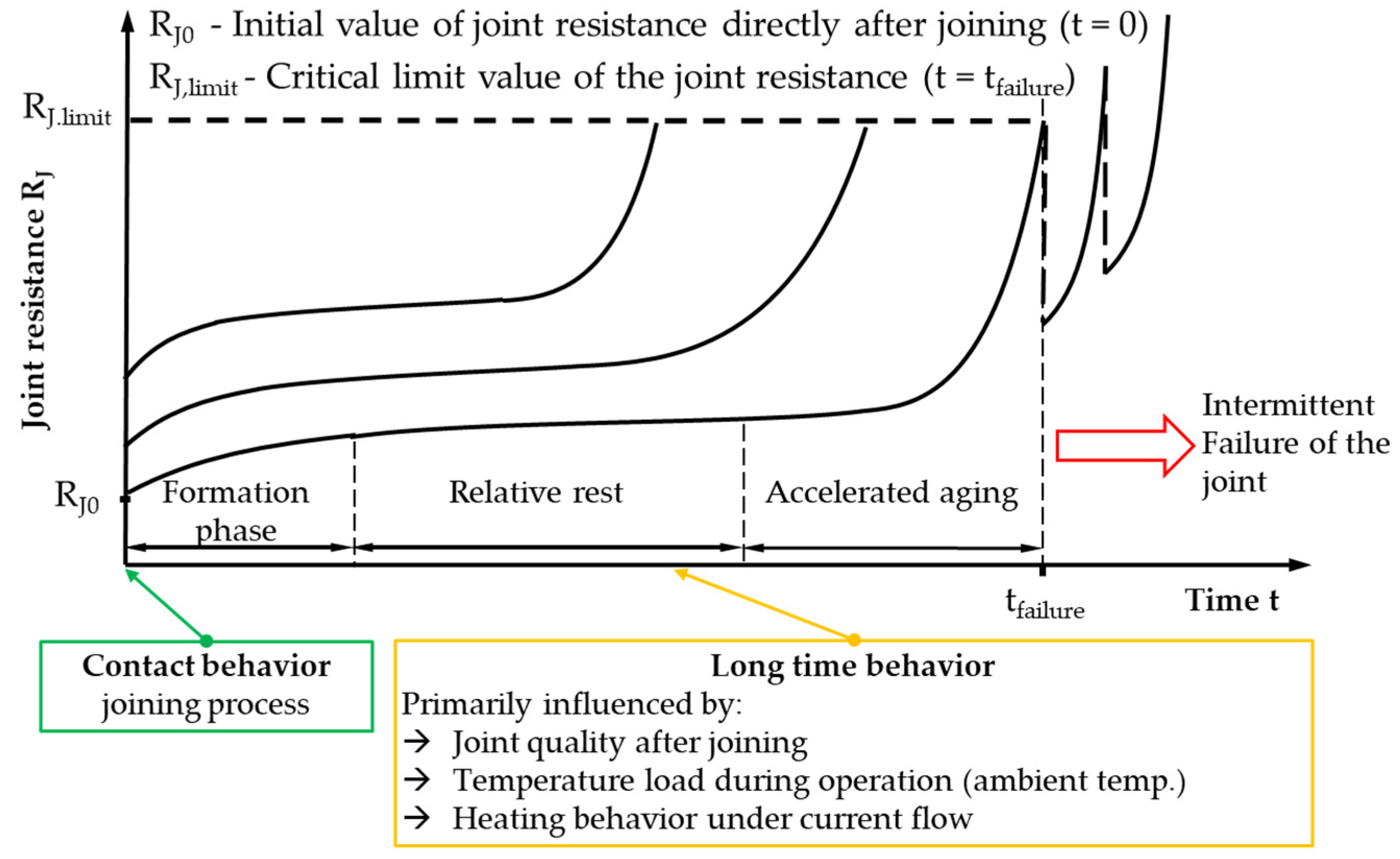
u0 > 1.17, the joint temperature is higher than the temperature of the connected conductor, which can lead to damage to immediately adjacent components and increase the speed of aging. The calculations are always based on the assumption that the load current in the conductors and the joint are identical. In addition to the contact behavior of the compounds at the initial state, their long-term behavior is of essential importance for the application. The typical service life characteristic of a current-carrying joint can be divided into three phases (Figure 6).
After joining, the formation phase begins in which the resistances increase slightly as a result of the first heating depending on the contact behavior of the respective conductors and the construction of the joint, or also decrease, for example, in the case of coated contact surfaces. This is followed by the phase of relative stability, which should cover the entire required service life for a joint with long-term stability. During this period, an infliction point is reached and the joint resistance changes only slightly. In the area of accelerated aging, the resistance of the joint increases significantly until its failure occurs. In addition to the quality of the assembly and the load acting on the joint, the relevant physical aging mechanisms are decisive for the aging process. The five aging mechanisms are force reduction by stress relaxation and/or creeping, chemical reactions (galvanic corrosion, oxide layer formation), which are particularly relevant for the investigated joints [7], inter-diffusion, which can occur in contact partners made of different metallic materials, and electro-migration as well as friction wear are known.
At electrical contacts, a temperature change occurs at the joint as a result of current flow depending on the quality of the joint, characterized by the performance factor ku (Figure 5). Due to the aging of the joining materials in the cold-formed areas of the clinched joint, an increased temperature leads to a force reduction in the joint, which represents a reduction in the force-fit component. The investigations aim to characterize and quantify the long-term behavior of clinched electrical contacts as a function of a thermal load.

2. Materials and Methods

2.1. Joining Materials

2.1.1. Cu-ETP (E-Cu58, C 11000, CW004A)

The Copper material Cu-ETP (Table 1) has very high conductivity for heat and electricity, a very good forming capacity as well as good corrosion resistance to climatic influences and water [14]. The electrical conductivity in the annealed condition is κ = 57 MS/m at 20 °C, 43 MS/m at 100 °C, and 55–57 MS/m at 20 °C in the cold-formed condition [14]. It contains a small amount of oxygen and is, therefore, not suitable for welding and brazing in reducing atmospheres. The Cu-ETP used for the investigations is in the R240 state, which means a minimum tensile strength of 240 N/mm2. The Cu-ETP used for the following investigations is used in bare conditions with thicknesses of s = 1.0 mm and s = 2.0 mm.

2.1.2. EN AW-6016

The aluminum material is used in the T4 heat treatment condition (solution-annealed and work-hardened). After clinching, precipitation hardening to the T6 condition was carried out according to the manufacturer’s instructions [15] for 20 min at 185 °C. It has a passivated surface. In this process, the non-uniform oxide layer of the Al surface is removed and replaced by a defined thin and resistant conversion layer. No further surface treatment or preparation is carried out. The electrical conductivity in the unconsolidated state is κ = 26–30 MS/m at 20 °C [15]. The chemical composition is described in Table 2. This material was used with a thickness of s = 2.0 mm for the investigations carried out.

2.2. Tested Clinch Joints

The tests were carried out on clinch joints with a nominal diameter of 8 mm. A single-stage round joint with a closed die was used. The specimen geometry used for the tests had the dimensions 20 mm × 55 mm with an overlap of 16 mm. This geometry was chosen to achieve comparability of the results with [5].
The clinched joints with conductors of Cu-ETP (Wieland-Werke AG, Ulm, Germany) and mixed joints of Cu-ETP and EN AW-6016 (Novelis Deutschland GmbH, Göttingen, Germany) of the same thickness as well were investigated (Table 3). Long-term behavior was examined by using a climate chamber (temperature uniformity of conductor and joint) and at an electric circuit (temperature difference of conductor and joint).
The aim of these investigations is the clinching of electrical conductors and the targeted exploitation of the effects inherent in the process, such as the surface enlargement and the relative movement of the joining partners and their effect on the joint resistance. The surface enlargement and relative movement during the clinching process are conducive to an increased number and size of a-spots. Due to the relative movement, the oxide layers on the surface of the contact partner crack and the unoxidized material of the contact partners are brought closer together in superposition with the surface pressure occurring between the joining partners. This promotes the formation of a-spots. While manufacturing the clinched joint, impurity layers tear open, which can also be regarded as a cleaning effect. In addition to the neck area, the bottom area of the clinched joints has a large influence on conductivity [16]. However, a-spots can increasingly be created due to a large force-fit component. The mechanical properties are not or only to a small extent influenced.
To indicate these effects, two different Cu-Cu joints were designed. Starting from a clinch joint of two copper conductors with a thickness of s = 1.0 mm each, the manufacturing parameters were changed according to the effects mentioned for the second Cu-Cu combination with component thicknesses of s = 2.0 mm each. A larger penetration depth of the punch increases the relative movement between the joining partners and, thus, the apparent contact area between the joining partners

2.3. Testing

To determine the electrical properties of the clinched joints, the joint resistance and the performance factor were determined. The four-wire measurement method (Kelvin-Method) was used to measure the joint resistance (Figure 7). Jiang [17] uses, for instance, the electrical resistance measurement as a non-destructive test of clinched aluminum and steel joints from a mechanical point of view, but not for electrical tasks.
A micro-ohmmeter (LoRe, Werner GmbH, Kreischa, Germany) is used to inject a direct current Imeasure into the specimen via wires 1 and 2 and measure the voltage drop across the clinched joint through wires 3 and 4, taking into account any thermoelectric voltages that occur. With the injected measuring current Imeasure and the measured voltage drop Umeasure, the connection resistance is calculated via Ohm’s law. In addition, the temperature of the joints was determined to calculate the resistance converted to a reference temperature of 20 °C from all variables.
On the clinched specimens, the resistance across the joint was determined at a distance of 19 mm between the potential measurement points. The overlap length of the conductors was 16 mm, so the resistance of the conductor material present at 1.5 mm was then subtracted from the measured resistance. In addition, a specific reference value of the conductor resistance was determined depending on the used conductor materials.
In the first step, the electrical quality of the joints after clinching, i.e., the contact behavior, was documented by the performance factor ku0. In the next step, the clinched specimens were subjected to thermal stress in a climate chamber for a period of 1000 h at 80 °C, 100 °C, and 120 °C. The selection of the loading temperatures was made according to the temperature classes defined in [18].
This resulted in temperature uniformity between the homogeneous conductor and the clinched joint. During this period, the electrical resistance was measured and evaluated cyclically. Subsequently, the investigations were continued using the same samples for at least another 5000 h in current-carrying tests. Again, the electrical resistance of the clinched connection was measured and documented at time intervals.
For the preparation of the metallographic cross-sections, the specimens were first embedded in a 2-C epoxy resin. After sample separation, grinding was performed in several steps up to a grain size of P4000 (3 microns), followed by polishing with aluminum oxide particle suspension (grain size 0.05 microns) and etching with Barker solution to visualize the microstructure. For image acquisition, a digital microscope of the type Zeiss Smart Zoom 5 (Carl Zeiss Microscopy Deutschland GmbH, Oberkochen, Germany) was used.
The quasi-static shear tensile test (inspekt blue 10 kN, Hegewald & Peschke Meß- und Prüftechnik GmbH, Nossen, Germany) of the clinched specimens was performed according to [1,19]. The test speed was 5 mm/min. The stopping criterion of this test was a force drop of 90% of the maximum force.

3. Results

3.1. Electrical Behavior

The clinch joints with copper materials of thickness 1.0 mm as contact partners show stable long-term behavior over 6000 h for the entire loading period at a constant temperature of 80 °C in the climate chamber. The samples with a thickness of 2.0 mm each behave in the same way at a constant temperature of 120 °C in the climatic chamber and at a homogeneous conductor temperature of 120 °C set by current flow. The only difference between the series is the performance factor ku0 and the load temperature.
The clinched joints with contact partners out of copper materials first pass in both series of the formation phase (Figure 8). In the case of the samples, with an exclusively thermal load in the climatic chamber at 80 °C, this formation phase is completed after approx. 1000 h, and the clinched joint enters the phase of relative stability. In the further course under this load, the performance factor of the specimen does not change significantly, and long-term stable behavior is present until the end of the load after 6000 h. The performance factor ku0 = 1.5 reaches a value of ku6000 = 1.5 after 6000 h.
In a second test series, the samples with a thickness of 2.0 mm each were first subjected again to a constant thermal load in the climate chamber at a temperature application of 120 °C (Figure 8). After a period of 1000 h, the load in the climate chamber was terminated. Further thermal loading was carried out on current-fluxed conductors, whereby a temperature of 120 °C was set in the homogeneous conductor by the test current. As a result of the initial performance factor of ku0 = 1.3, a slight temperature difference between the clinched joint and the homogeneous conductor occurs (compare Figure 5). This temperature difference leads to an increased performance factor, and it stabilizes at a value of 1.4 and does not change anymore until the end of the load after 4000 h, so the marginally increased temperature does not affect the electrical behavior of the clinched joint. With this type of loading, long-term stable behavior of the clinched joints could also be observed.
Clinched joints with conductor materials made of copper and aluminum do not show stable long-term behavior at a constant thermal load of 120 °C in the climate chamber (Figure 9). After only a few hours of thermal stress, the performance factor increases from ku0 = 1.2 to ku1000 = 4 and, after 5000 h, to ku5000 = 27.95. This increase in the performance factor after a short time is not only due to a reduction in the force-fit component but also to the fact that the joint is no longer gas-tight due to the different linear thermal expansion coefficients, and oxidation can occur in the area of the joint. This increased performance factor indicates a significant change in the electrical resistance and leads to an increasing temperature at the joint and, thus, accelerating aging of the a-spots, which leads to a failure of the joint (Figure 9). To exclude the influence of oxidation on aging, experiments were carried out in [5] in a glove box under an inert atmosphere. As a result of these tests, it was found that aging was not prevented but slowed down. Thus, the reduction in the force-fit component at the clinched joint is the dominant aging mechanism.
With the reduction in the thermal load by 20 K, the investigated mixed joints show a long-term stable behavior in both joining part arrangements. A distinction must be made between the arrangement of the thermal-sensitive aluminum (Figure 9). Starting from an initial performance factor of ku0 = 1.2 for the die-side arrangement and ku0 = 1.5 for the punch-side arrangement, quality factors of 1.3 and 1.6 are achieved for the punch-side arrangement of the aluminum material after 3000 h. If the load continues up to a period of 5800 h, the performance factors change only slightly. If the aluminum material is placed on the die-side and a temperature of 80 °C is set, no failure of the clinched joint can be detected even after a loading period of app. 10,000 h.
Evaluation of the long-term behavior of the clinch joints at a temperature of 100 °C shows that the limit temperature of the investigated material pairing and the joining method used is between 100 and 120 °C. At a loading temperature of 120 °C, the homologous temperature of the aluminum THAl is 0.42. At this temperature, creep and recrystallization processes can already occur in the material as a function of the introduced deformation, which leads to a reduction in the force-fit component as a result of the force reduction between the joining partners. The long-term behavior of the clinch joints at a temperature of 100 °C is stable. In addition to the long-term stability, there is also a significantly reduced scatter band of the measured resistance values (Figure 9). Fuhrmann [20] describes and analyses the same temperature- and time-dependent behavior of aluminum materials for bolted joints with aluminum bus bars and determines the permissible limit temperatures at which there is no influence on the operating time.

3.2. Mechanical Behavior

The mechanical tests before and after the thermal and electric-thermal load of the clinch joints made it possible to measure sufficient connection strength to secure the fragile current-carrying a-spots between the joining partners by the form- and force-fit components. During mechanical testing, the form-fit and force-fit components counteract the relative movement of the joining partners at the clinched joint and, thus, mechanically secure the fragile a-spots. To ensure the strength of the joints and to show the changes in the joining component materials caused by thermal and current load, the clinch joints were subjected to a quasi-static shear tensile test before loading and after the various loads (Figure 10). These tests are necessary to be able to show any influences on the form- and force-fit components due to aging over the period of use. The thermal loads are described in Section 3.1. Electrical behavior also affects the load-bearing behavior of the clinch joints.
In the case of the copper series of the same type, an increase in the test loads of approx. 25%, with a simultaneous increase in the scatter band, can be recorded, which can be attributed to strain aging (Figure 10). The clinching process work-hardens the materials to be joined. Subsequent delivery at elevated temperatures leads to a change in the material properties, such as an increase in yield strength due to the blocking of dislocation movements by foreign atoms. This effect of strain aging explains the increased shear forces present in this case. The strain aging is determined by the degree of deformation, the aging time, and the aging temperature. Concerning the specimen failure, an almost identical appearance of a combined geometric and material failure is recognizable.
In the case of mixed joints with conductors made of aluminum and copper (Figure 11), the test load is increased by 70% in comparison to the initial state when the aluminum material is arranged on the punch side after complete aging for 5000 h at 100 °C, which is attributable to the onset of precipitation hardening. After loading at 120 °C, there is a significant drop in the test load, which indicates a stress reduction within the aluminum material. The failure diagrams in Figure 11 for this joining part combination show nearly identical failure behavior. All combinations failed due to neck breakage (material failure) without previous deformation of the punch-side material at the clinched joint. Due to the undefined heat treatment during aging and the inhomogeneous microstructural changes at the clinched joint, the standard deviation increases.
If the aluminum material is arranged on the die side, similar behavior of the test loads can be observed after the quasi-static shear tensile test. After aging at 100 °C, the test load increases significantly compared to the initial state after clinching. After removal from storage at 120 °C, the test load drops again, but not to the level of the initial condition.
These series show an identical fracture pattern to the initial condition (combined failure due to deformation of the punch-side material at the clinched joint and shearing off of the neck area). For the series Al-Cu and Cu-Al, there is no significant difference between the initial and the aged condition at 100 °C about the test load. After aging at a temperature of 120 °C, a higher test load can be measured compared to the punch-side arrangement of the aluminum material, which can be attributed to a less severe stress reduction (lower degrees of deformation in the aluminum joining partner) as a result of the thermal load.

4. Discussion

The deformed state of a material is fundamentally thermodynamically unstable [21]. The strain hardening, produced by the clinching process, affects the residual stress state of the joint. This is superimposed by load stresses and can influence mechanical, thermal, and electrical properties. This depends especially on the degree of deformation of the conductor material and the operating temperature. Residual stress determinations were carried out using X-ray and neutron diffraction on clinch joints of the same type [22]. In both base materials, residual compressive stresses are present in the range up to approx. (4–6) mm from the clinched joint when closed dies are used. Outside this distance of approx. (4–6) mm from the clinched joint, tensile residual stresses are present [22]. Under the influence of thermal load, this residual stress condition will change. The stresses arising at the clinched joint, which are caused by the difference in the coefficients of thermal expansion of the individual conductor, superimpose these residual stresses.
The deformation-induced dislocation structure is not part of the thermodynamic equilibrium. At a sufficiently low forming temperature, the deformation structure is retained because it is mechanically stable. This mechanical stability can be overcome by increasing the temperature [21]. The required temperature to overcome the mechanical stability of the deformation structure depends especially on the material and the degree of deformation involved. The greater the degree of deformation, the lower the temperature for overcoming the deformation structure.
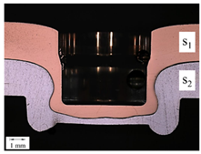
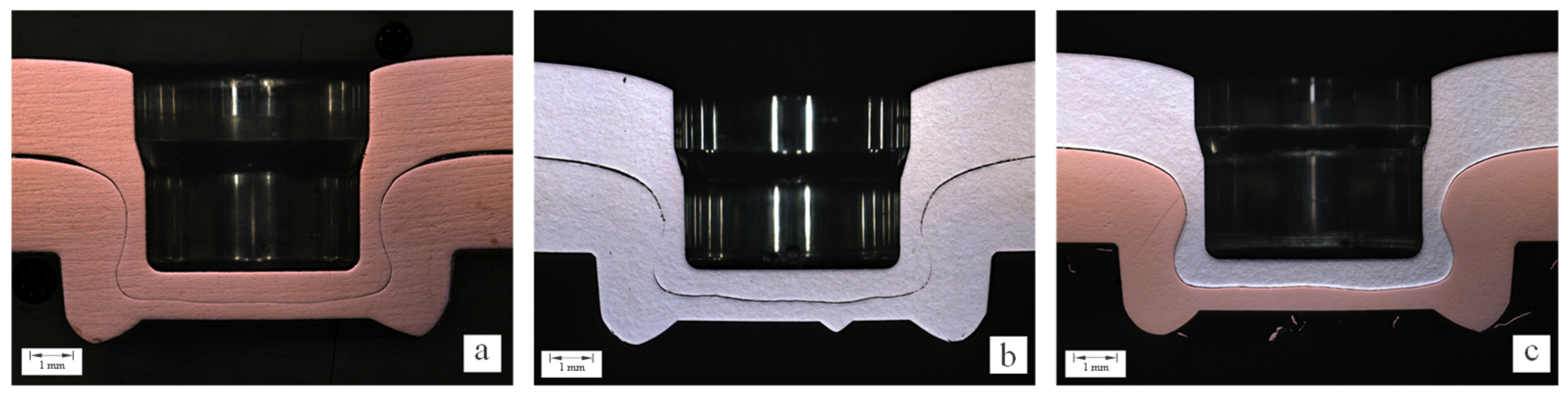
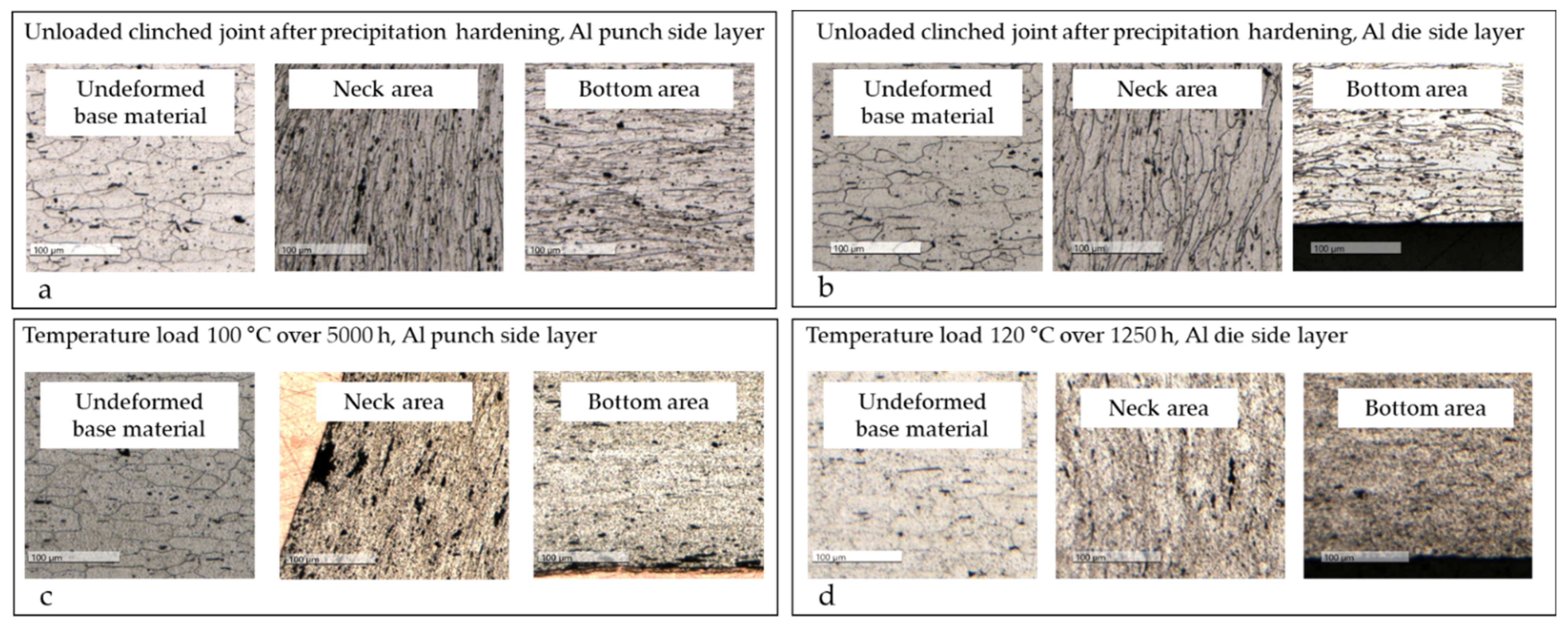
When considering the microstructure of the areas with the greatest deformation (neck and bottom areas), a microstructure change can be seen at the time after joining and without thermal stress, caused by the deformation (Figure 12a).
In the neck area, the crystallites are axially elongated. In the bottom area, the crystallites are radially elongated as a result of the material flow to adjust the bottom thickness. The undeformed material outside of the clinched joint is a basis for comparison. By the arrangement of the aluminum in the die-side position, smaller changes in shape are introduced, which results in less deformation of the crystallites (Figure 12b).
If a thermal load of 100 °C is now applied for 5000 h, a change can be seen in Figure 12c in all three areas. The grain shape and grain orientation in the base material remain unchanged, and only primary precipitations occur. The grain orientation can still be seen in the neck and bottom areas, but the grain boundaries are difficult to identify. A load-related structural change has taken place here, but this does not hurt the long-term behavior of the clinched joint regarding the electrical properties in Figure 9. The operating temperature limit is not reached.
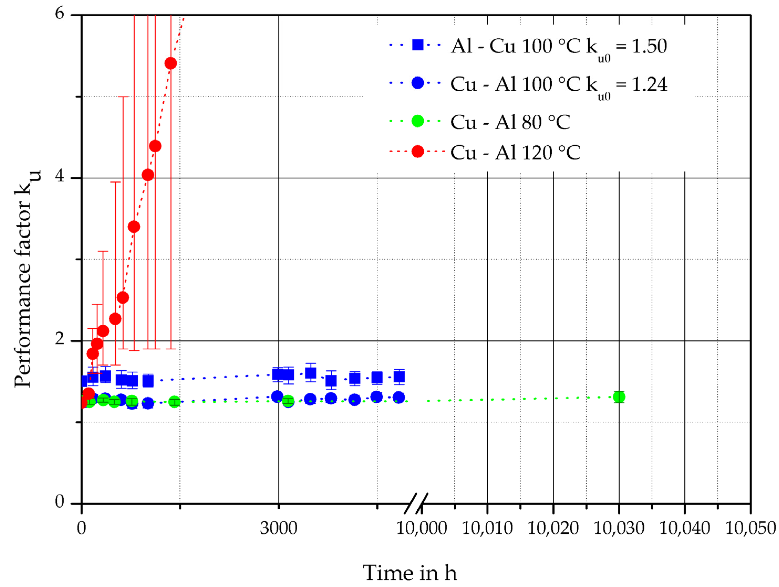
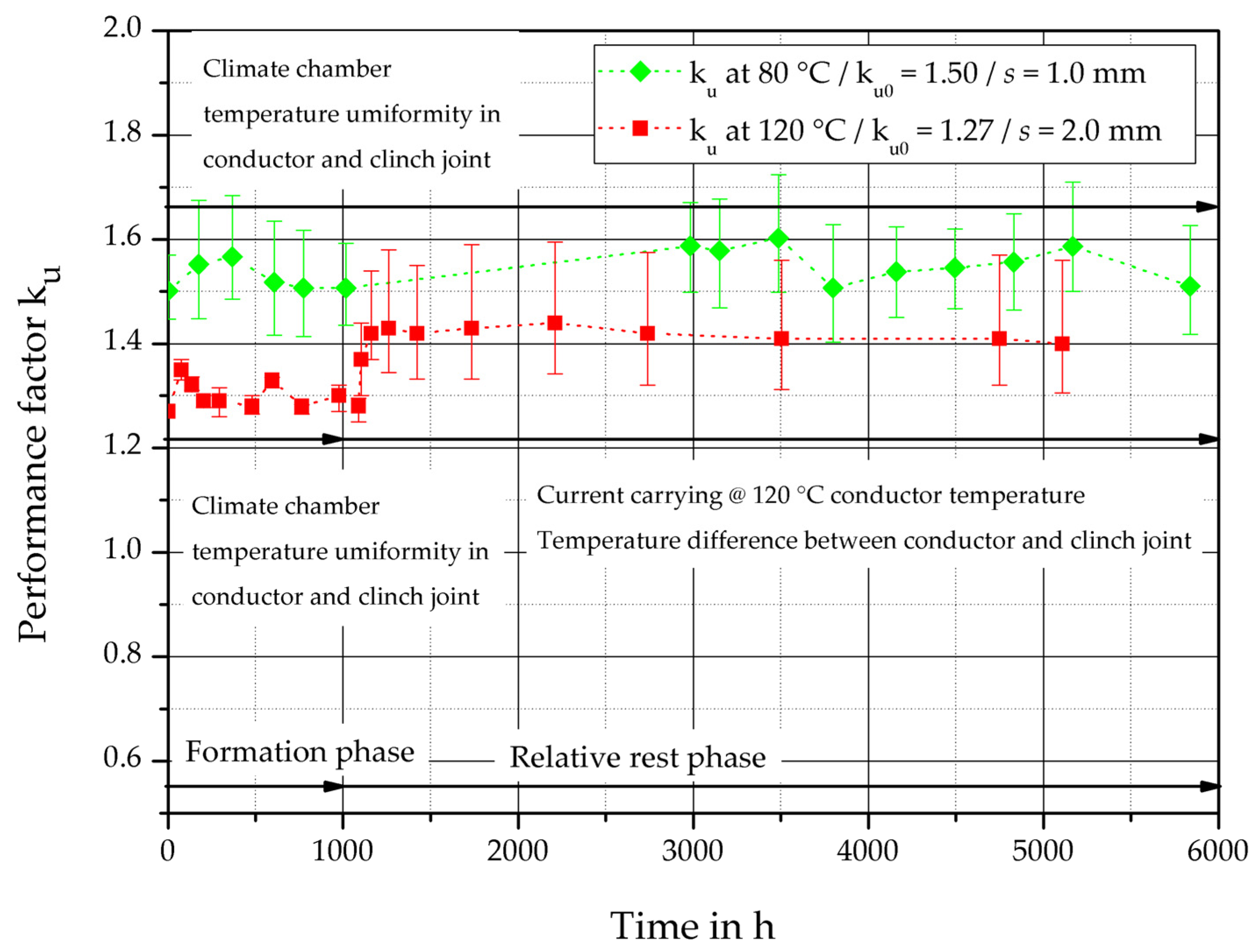
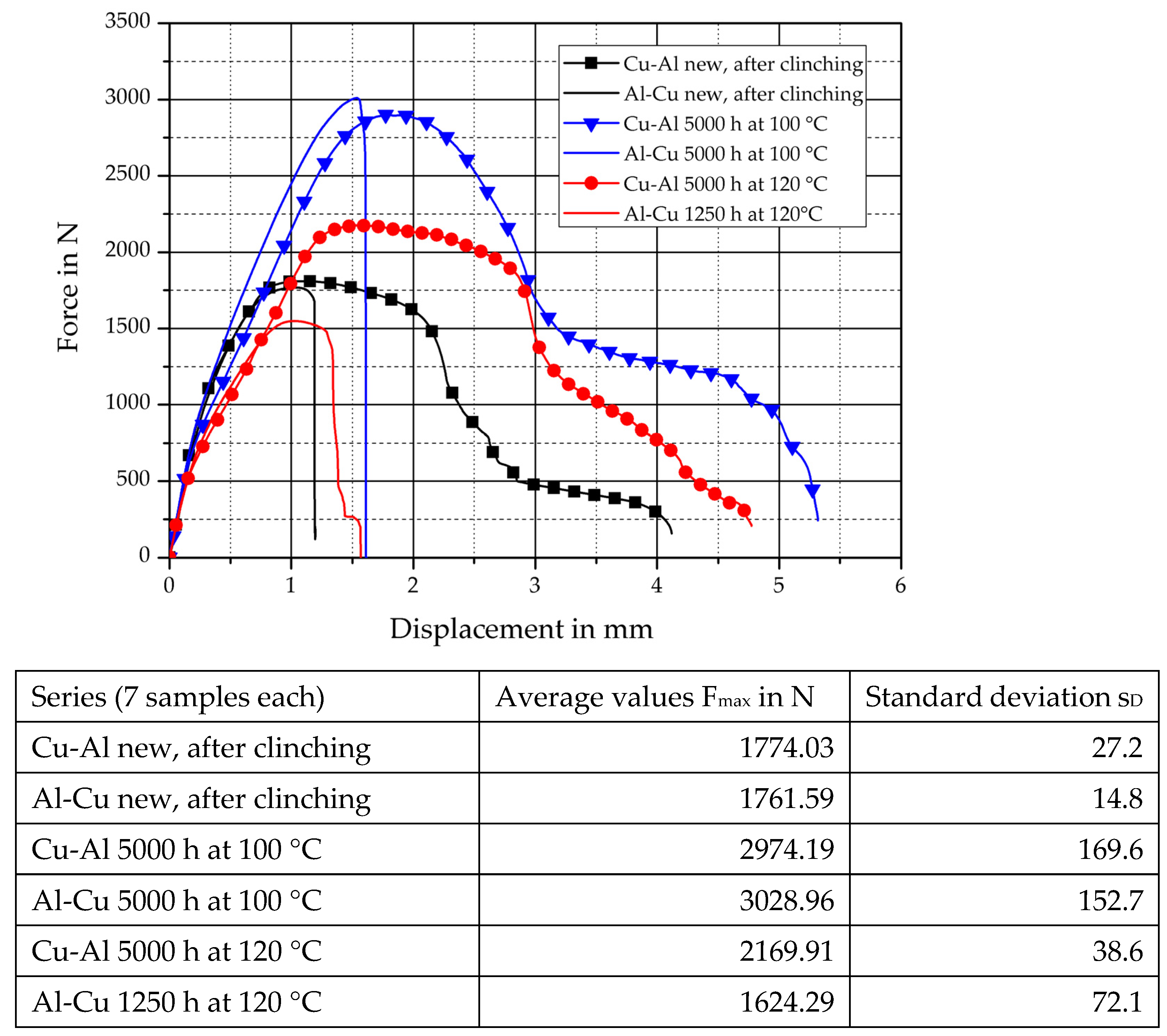
At temperatures of 80 °C and 100 °C, the force dissipation in the joint is low and there is no influence on the joint resistance and, thus, the performance factor during this period. At a temperature load of 120 °C, the performance factor increases significantly even after a very short load duration (Figure 9), so that the performance factor in the electrical test reaches a value of ku = 27.95 after 5000 h, which, from an electrical point of view, represents a failure of the connection. These joints failed due to the significant mechanical stress reduction (reduced force-fit component) between the joining partners caused by reaching the temperature limit in the deformed aluminum. This stress/force reduction between the conductors leads to an increased contact resistance Re, according to Equation (1).
Due to the large deformation of the joining materials, the recrystallization temperature is reduced. In this case, the load temperature is higher than the operating temperature limit. 
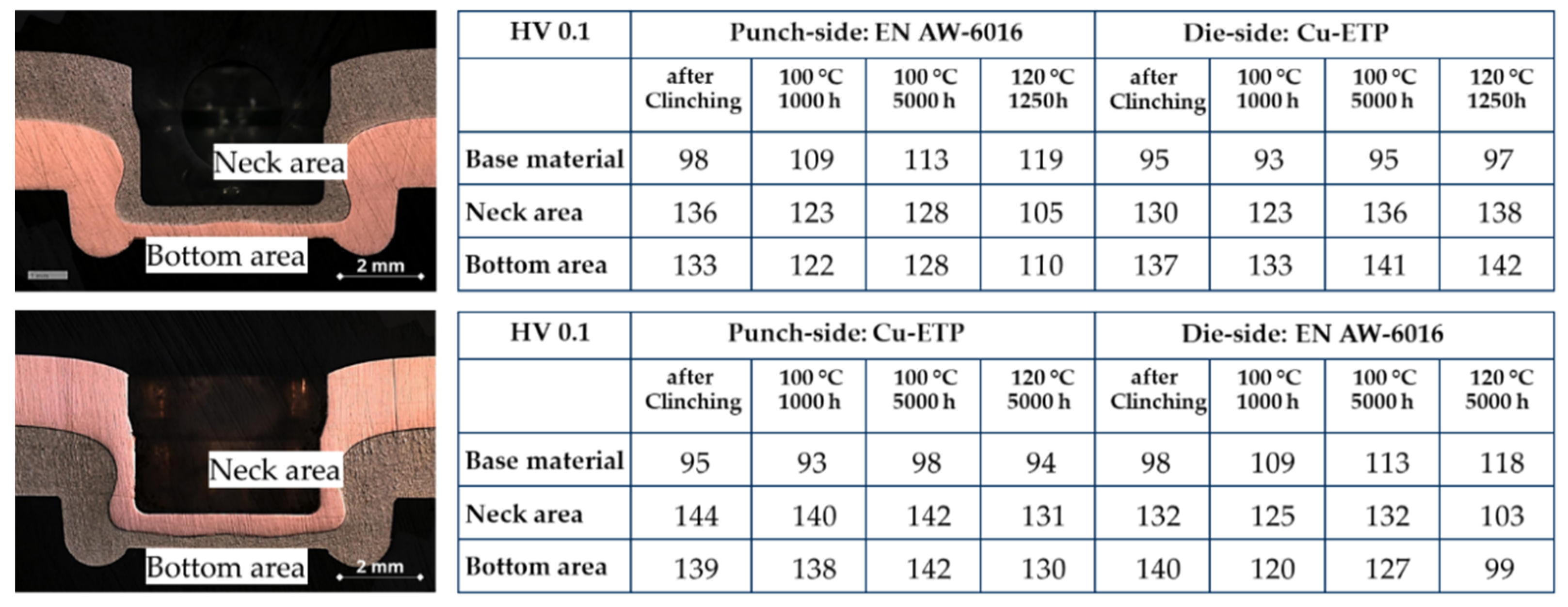
Figure 12d shows the microstructural changes that occurred in the specimens in the aluminum material on the die side, which caused the reduction in the force-fit component between the joining partners. By using hardness measurements (Figure 13), it can be determined that there is no change in hardness at a load of 100 °C in the copper material (Cu-ETP). About the aluminum material on the die side, there is a slight increase in hardness in the unformed base material, which can be attributed to the incipient precipitation hardening effects. There is no change in hardness in the neck area, where cold hardening is superimposed with a slight reduction in stress, whereas in the bottom area, despite cold hardening, there is a slight loss of hardness, but this does not affect the long-term behavior.
The clinch joint is examined in both joining directions. The punch-side arrangement of the copper material has similar effects to the clinched joint described above.
In the case of the aluminum material arrangement on the punch-side (Figure 13), there is a significant drop in hardness in the neck and base area after only a short time at a load of 120 °C, which leads to a reduction in the contact hardness (compare Equation (1)) and a frictional component due to stress relief. This effect has reflected an increase in the performance factor (Figure 9). With a thermal load below 100 °C, the structural changes and stress reduction do not hurt the long-term behavior of the joint (Figure 9).

5. Conclusions

Clinching is a useful joining technology for lightweight construction, multi-material design, and multi-functional joints. The first generation of fundamental statements on the behavior of joints manufactured by clinching in an electrical circuit can be pointed out. The extension of the application range of clinching processes for electro-technical applications can be presented. The clinched joint can be safely used as a current-carrying connection for aluminum materials up to 100 °C and for copper materials up to 120 °C. The performance factor ku can be used as a process and material independent criterion for comparison and evaluation. The optimized design of a clinched joint differs slightly in terms of optimizing the electrical or mechanical properties of the connection. For example, the relative movement of the joining partners during the joining process and the associated leveling of surface roughness, especially in the neck and bottom area, have a beneficial effect on a large contact area. Furthermore, the surface enlargement occurring during the joining process and the associated breaking of the natural oxide layer in aluminum materials, for the generation of a-spots, has a positive effect on electrical contacting.
The surfaces sliding on each other during the relative movement have a cleaning effect due to the removal of particles of the broken oxide layer.
These described effects have a positive effect on electrical contacting and a neutral effect on the mechanical connection strength. The reduction in the hardness of aluminum alloy caused by exceeding the temperature limit leads to the reduction in mechanical as well as electrical stability. This leads to a decrease in force-fit and increase in the joint resistance Rj as well as the temperature of the joint. This effect also takes place in a slower form in the absence of oxygen.
The limit of current and the limit of operation temperature must be adjusted to the joining partner. The take-over of electrical tasks into the joint, manufactured by clinching technologies, could be integrated, depending on the conductor materials and the electric-thermal load. The results of these investigations lead to an extension of the range of applications, products, and joining systems.

Author Contributions

Conceptualization, J.K. and S.S.; methodology, U.F.; validation, J.K., S.S. and L.K.; investigation, J.K., S.S. and L.K.; resources, W.P. and M.M.; writing—original draft preparation, J.K.; writing—review and editing, U.F., W.P., M.M. and S.S.; visualization, L.K.; supervision, U.F.; project administration, U.F.; funding acquisition, U.F. All authors have read and agreed to the published version of the manuscript.

Funding

This research was funded by the Deutsche Forschungsgemeinschaft (DFG, German Research Foundation)-TRR 285-Project-ID 418701707, subproject A04, and the IGF Project (AiF 16952BR) of the European Research Association for Sheet Metal Working was supported via AiF within the program for promoting the Industrial Collective Research (IGF) of the German Ministry of Economic Affairs and Climate Action (BMWK), based on a decision by the German Bundestag.

Institutional Review Board Statement

Not applicable.

Informed Consent Statement

Not applicable.

Data Availability Statement

All data generated in this study were included in this article.

Conflicts of Interest

The authors declare no conflict of interest.

References

  1. Deutscher Verband für Schweißen und Verwandte Verfahren. Taschenbuch DVS-Merkblätter und -Richtlinien, Mechanisches Fügen; DVS-Verl.: Düsseldorf, Germany, 2009; ISBN 9783871552304. [Google Scholar]
  2. Mucha, J. Clinching technology in the automotive industry. Arch. Automot. Eng. Arch. Motoryz. 2017, 76, 75–94. [Google Scholar] [CrossRef]
  3. Zwicker, M.; Moghadam, M.; Zhang, W.; Nielsen, C.V. Automotive battery pack manufacturing—A review of battery to tab joining. J. Adv. Join. Processes 2020, 1, 100017. [Google Scholar] [CrossRef]
  4. Das, A.; Li, D.; Williams, D.; Greenwood, D. Joining Technologies for Automotive Battery Systems Manufacturing. WEVJ 2018, 9, 22. [Google Scholar] [CrossRef]
  5. Füssel, U.; Kalich, J.; Großmann, S.; Schlegel, S.; Ramonat, A. Optimierung Um-Formtechnischer Fügeverfahren zur Kontaktierung Elektrischer Leiter; Europäische Forschungsgesellschaft für Blechverarbeitung e.V: Hannover, Germany, 2019; ISBN 978-3867765596. [Google Scholar]
  6. Rieder, W. Elektrische Kontakte: Einführung in die Kontaktphysik; VDE-Verlag: Berlin, Germany, 2000. [Google Scholar]
  7. Slade, P.G. (Ed.) Electrical Contacts: Principles and Applications, 2nd ed.; CRC Press: Boca Raton, FL, USA, 2014; ISBN 978-1-4398-8131-6. [Google Scholar]
  8. Holm, R. Electric Contacts: Theory and Application, 4th ed.; Springer: Berlin, Germany, 2000; ISBN 3-540-03875-2. [Google Scholar]
  9. Kogut, L. Electrical performance of contaminated rough surfaces in contact. J. Appl. Phys. 2005, 97, 103723. [Google Scholar] [CrossRef]
  10. Böhme, H. Mittelspannungstechnik: Schaltanlagen Berechnen und Entwerfen, 2nd ed.; Huss-Medien Verl. Technik: Berlin, Germany, 2005; ISBN 3-341-01495-0. [Google Scholar]
  11. Kalich, J.; Füssel, U. Influence of the Production Process on the Binding Mechanism of Clinched Aluminum Steel Mixed Compounds. JMMP 2021, 5, 105. [Google Scholar] [CrossRef]
  12. Steinfelder, C.; Kalich, J.; Brosius, A.; Füssel, U. Numerical and experimental investigation of the transmission moment of clinching points. IOP Conf. Ser. Mater. Sci. Eng. 2021, 1157, 12003. [Google Scholar] [CrossRef]
  13. Bergmann, R. Zum Langzeitverhalten des Widerstands Elektrischer Stromschienen-Verbindungen; Dissertation TU Dresden; VDI-Verl.: Düsseldorf, Germany, 1996; ISBN 3183195216. [Google Scholar]
  14. Deutsches Kupferinstitut Berufsverband, e.V. Datasheet Cu-ETP—CW004A (2.0065, 2.0060), Düsseldorf, 2005. Available online: https://www.kupferinstitut.de/wp-content/uploads/2019/11/Cu-ETP.pdf (accessed on 29 September 2022).
  15. Novelis Global Automotive. Datasheet Automotive Novelis Advanz™ 6HF—e200; Novelis Global Automotive: Kuesnacht, Germany, 2019. [Google Scholar]
  16. Füssel, U.; Großmann, S.; Kalich, J.; Schlegel, S.; Schmid, J. Elektrisches Eigenschaftsprofil Umformtechnischer Fügeverbindungen; Europäische Forschungsges für Blechverarbeitung: Hannover, Germany, 2014; ISBN 978-3-86776-432-2. [Google Scholar]
  17. Jiang, T.; Liu, Z.X.; Wang, P.C. Quality inspection of clinched joints of steel and aluminum. Int. J. Adv. Manuf. Technol. 2015, 76, 1393–1402. [Google Scholar] [CrossRef]
  18. Zentralverband Elektrotechnik- und Elektronikindustrie. Technischer Leitfaden—TLF 0214: Validierung von Automotive-Niedervolt-Steckverbindern; Zentralverband Elektrotechnik- und Elektronikindustrie: Frankfurt am Main, Germany, 2021. [Google Scholar]
  19. EN ISO 6892-1:2019; Metallische Werkstoffe—Zugversuch—Teil 1: Prüfverfahren bei Raumtemperatur. Beuth Verlag: Berlin, Germany, 2019.
  20. Fuhrmann, T. Kontakt- und Langzeitverhalten von Stromführenden Schraubenverbindungen Mit Vernickelten und Versilberten Leitern aus Aluminiumwerkstoffen; Technische Universität Dresden: Dresden, Austria, 2020. [Google Scholar]
  21. Gottstein, G. Physikalische Grundlagen der Materialkunde: Mit 28 Tabellen, 3rd ed.; Springer: Berlin/Heidelberg, Germany, 2007; ISBN 978-3-540-71104-9. [Google Scholar]
  22. Gibmeier, J.; Lin, R.; Odén, M.; Scholtes, B. Residual Stress Distributions around Clinched Joints. MSF 2002, 404–407, 617–622. [Google Scholar] [CrossRef]
Figure 1. Cross-section of clinched joints: (a) Cu-Cu, (b) Al-Al, and (c) Al-Cu.
Metals 12 01651 g001
Figure 2. (a) Characteristic designing parameters, (b) closure types of a clinched joint, (c) EDX analysis of surface.
Metals 12 01651 g002
Figure 3. Clinched fuses at a bus bar.
Metals 12 01651 g003
Figure 4. Representation of the tapping of the material resistances and the connection resistance on a clinch sample.
Metals 12 01651 g004
Figure 5. Distribution of the temperature at a temperature of 120 °C on the unaffected conductor depending on the performance factor ku0 of longitudinal connections with contact partners made of Cu-ETP.
Metals 12 01651 g005
Figure 6. Lifetime characteristics of current-carrying connections according to [13].
Metals 12 01651 g006
Figure 7. Principle of the resistance measurement of the clinched samples.
Metals 12 01651 g007
Figure 8. Performance factor ku of clinch joints with a contact partner made of Cu-ETP as a function of time and temperature.
Metals 12 01651 g008
Figure 9. Performance factor ku of clinched connections with contact partners made of Cu-ETP and AlMg0.4Si1.2 as a function of time and temperature load.
Metals 12 01651 g009
Figure 10. Quasistatic shear load—comparison of Cu-Cu clinch joints after long-term tests.
Metals 12 01651 g010
Figure 11. Quasistatic shear load—comparison of Cu-Al and Al-Cu clinch after long-term-tests.
Metals 12 01651 g011
Figure 12. (a,b) Microstructural condition after clinching without load, (c,d) after a thermal load.
Metals 12 01651 g012
Figure 13. Hardness measurement in areas of maximum forming joining combination Cu-ETP, s1 = 2.0 mm/EN AW-6016, s2 = 2.0 mm each materiel as punch and die side layer according to [5].
Metals 12 01651 g013
Table 1. Chemical composition of Cu-ETP [14].
Weight Percentage
CuBiOPbOthers (Excluded Ag, O)
min 99.9max 0.0005max 0.04max 0.0050.03
Table 2. Chemical composition of EN AW-6016 [15].
Weight Percentage
MgSiFeCuMnCrZnTiOthers, Each
≤0.25–0.601.0–1.5≤0.50≤0.20≤0.20≤0.10≤0.20≤0.15≤0.05
Table 3. Overview of the clinch joints examined.
MicrographJoining PartnersLoad
Metals 12 01651 i001Punch-side:
Cu-ETP s1 = 1.0 mm
Die-side:
Cu-ETP s2 = 1.0 mm
The constant temperature at 80 °C (the equal temperature at the conductor and joint)
Metals 12 01651 i002Punch-side:
Cu-ETP s1 = 2.0 mm
Die-side:
Cu-ETP s2 = 2.0 mm
The constant temperature at 100 °C (the equal temperature at conductor and joint)
Constant current with a conductor temperature of 120 °C
Tensile test at shear-load specimen before and after thermal load
Metals 12 01651 i003Punch-side:
Cu-ETP s1 = 2.0 mm
Die-side:
EN AW-6016 s2 = 2.0 mm
Constant temperatures of 80 °C, 100 °C, and 120 °C
Tensile test at shear-load specimen before and after thermal load
Metals 12 01651 i004Punch-side:
EN AW-6016 s1 = 2.0 mm
Die-side:
Cu-ETP s2 = 2.0 mm
Constant temperature 100 °C
Tensile test at shear-load specimen before and after thermal load
Publisher’s Note: MDPI stays neutral with regard to jurisdictional claims in published maps and institutional affiliations.

