
Effect of Titanium Based Alloys on Thermo-Mechanical Behavior in 3D Forging Simulation

 ,
,  , ,
, ,  ,
,  ,
,  and
and
Abstract
:1. Introduction
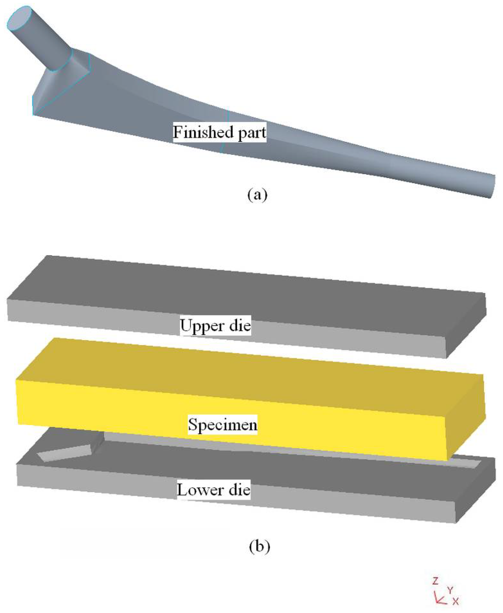
2. Materials and Methods
3. Results
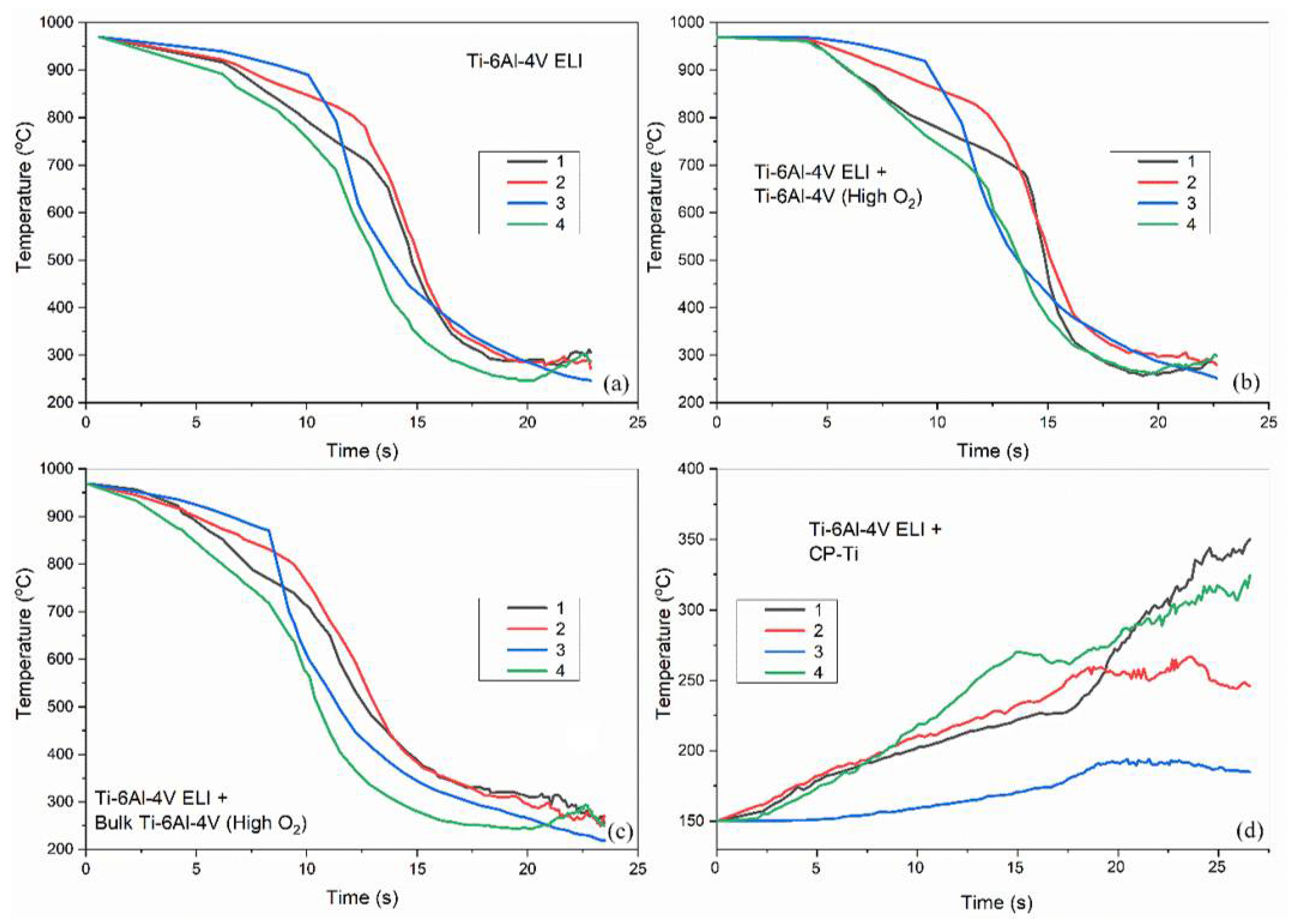
3.1. Mechanical Partition
3.2. Properties Analysis of Finished Part at Different Points
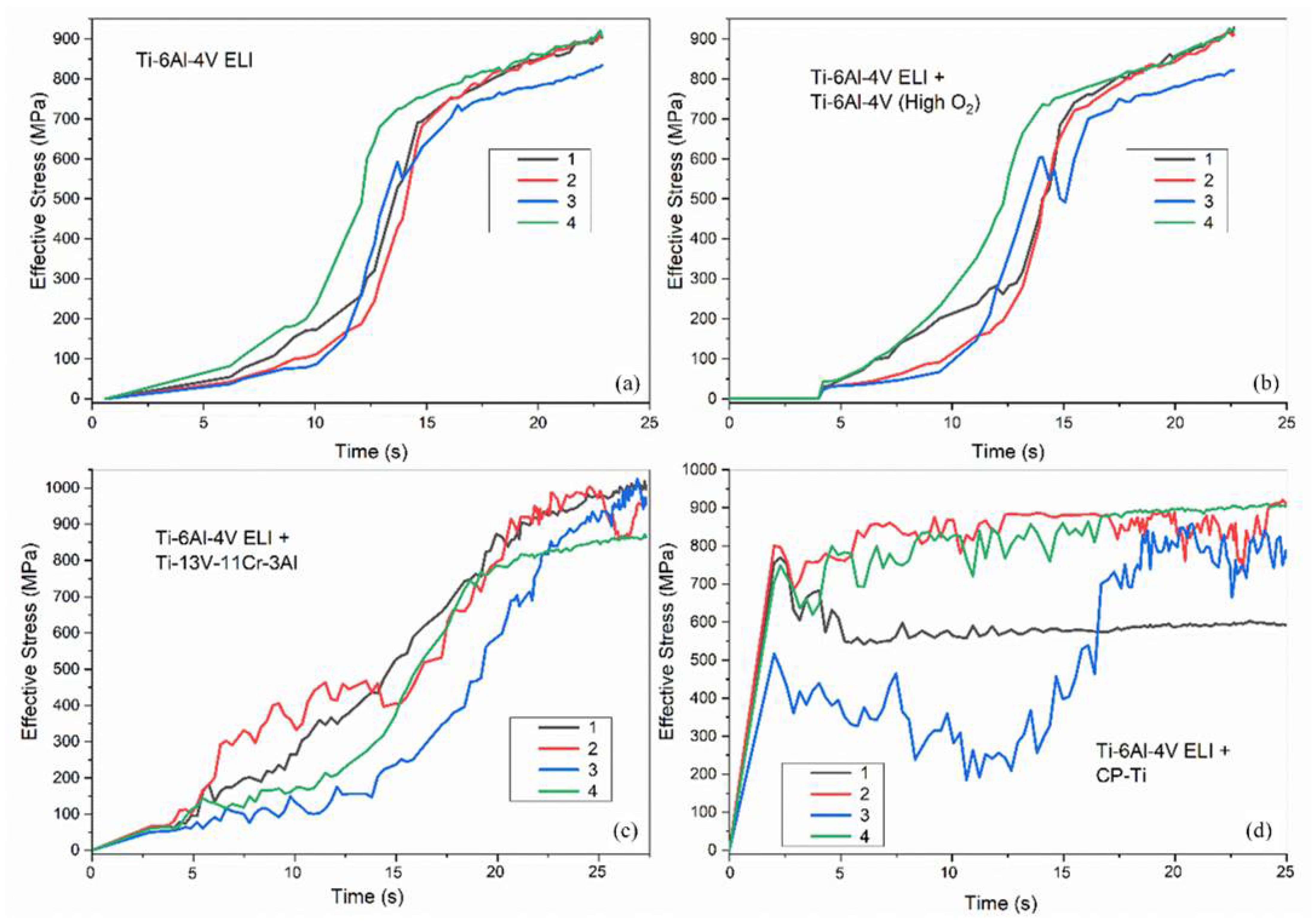
3.3. Effective Stress
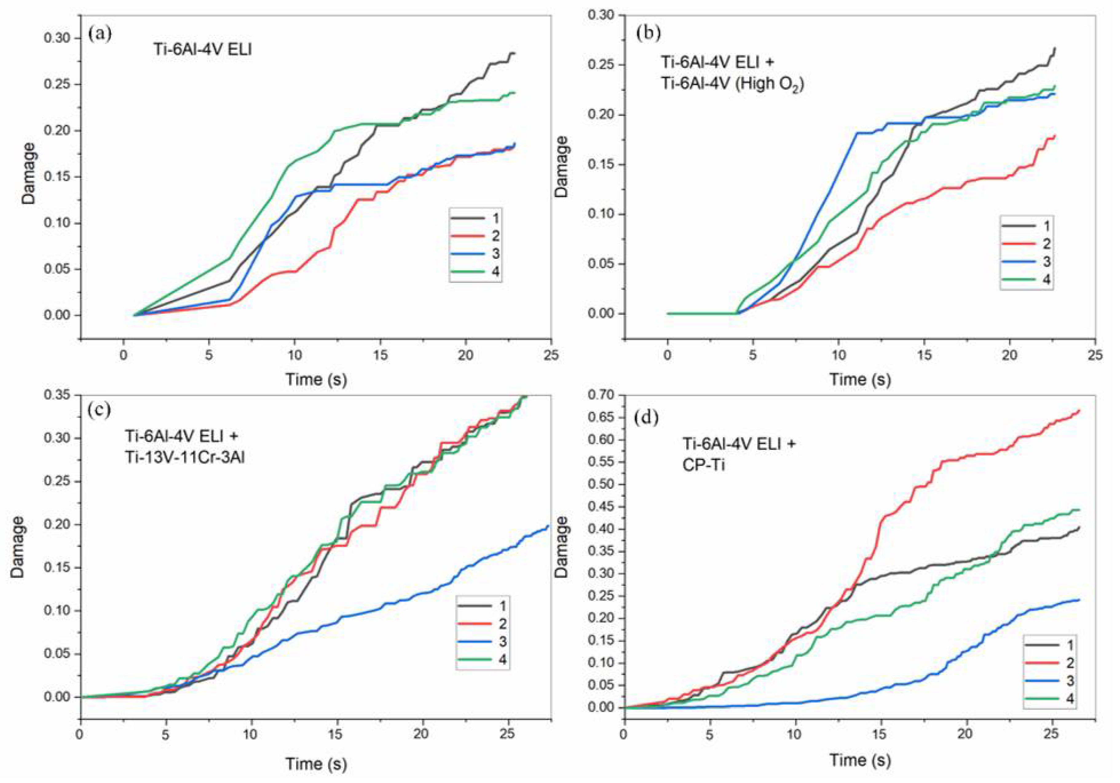
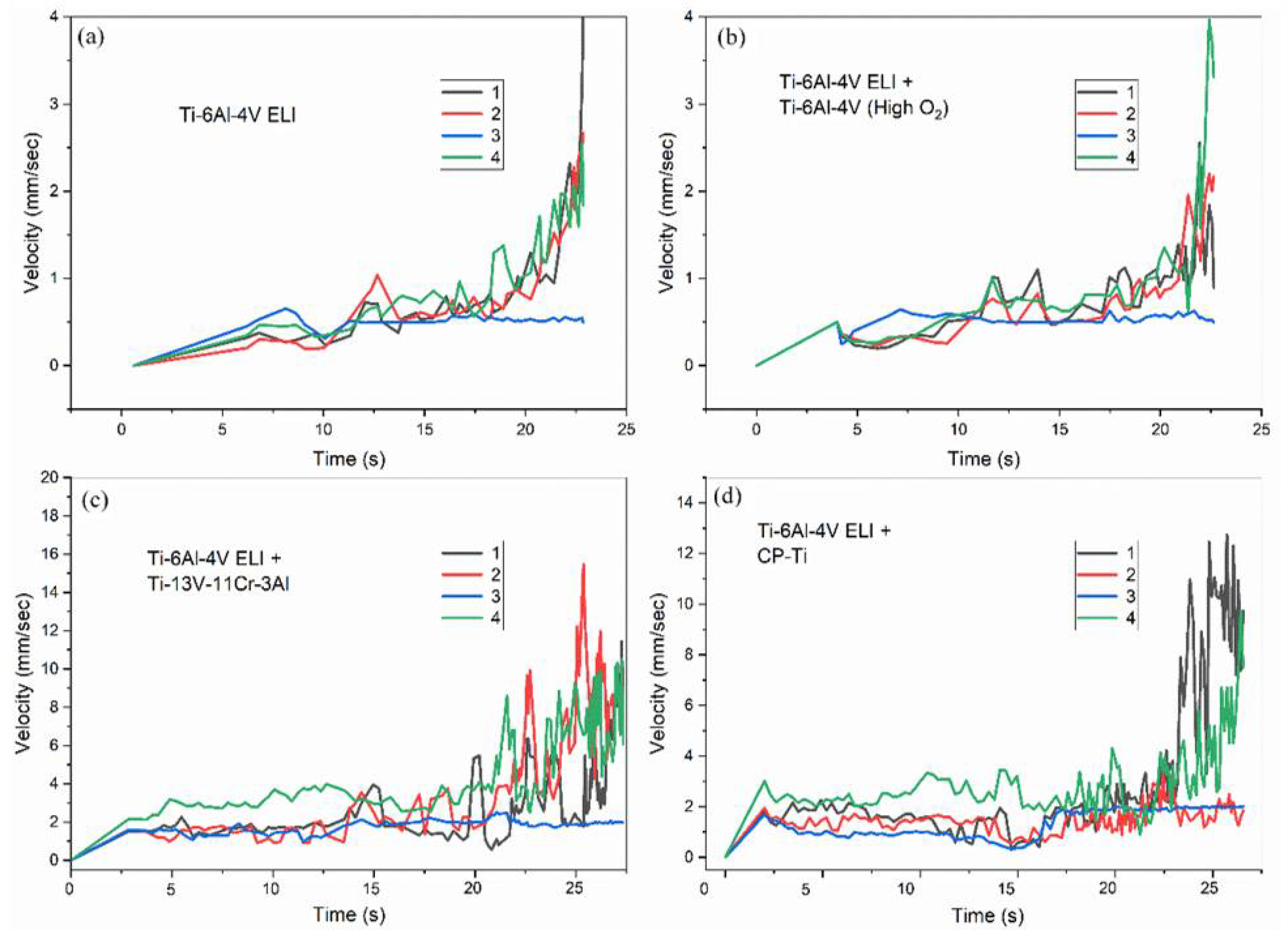
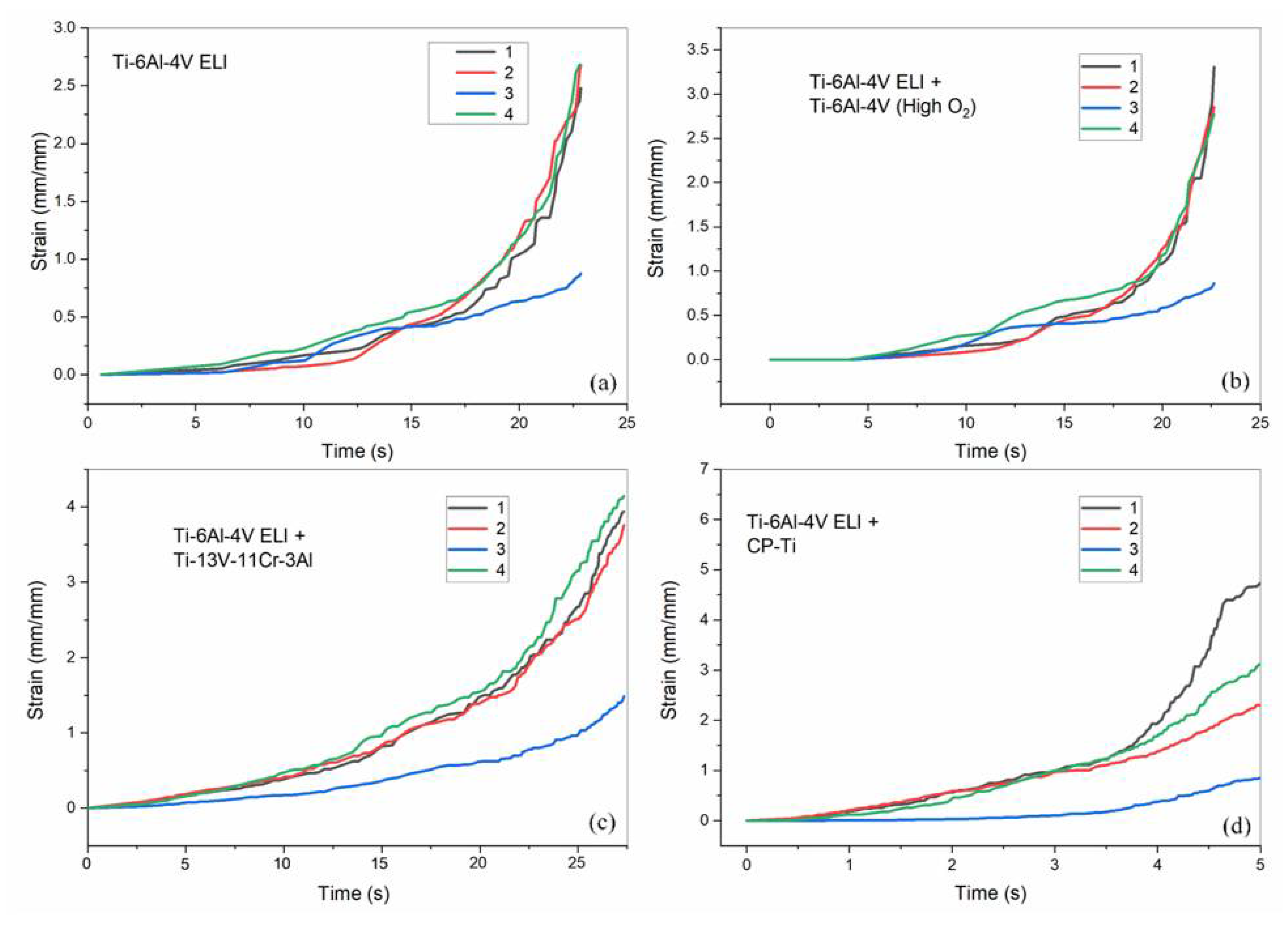
3.4. Damage, Velocity, and Strain
4. Conclusions
Author Contributions
Funding
Institutional Review Board Statement
Informed Consent Statement
Data Availability Statement
Conflicts of Interest
References
- Krishnan, R.; Pandiaraj, S.; Muthusamy, S.; Panchal, H.; Alsoufi, M.S.; Ibrahim, A.M.M.; Elsheikh, A. Biodegradable magnesium metal matrix composites for biomedical implants: Synthesis, mechanical performance, and corrosion behavior—A review. J. Mater. Res. Technol. 2022, 20, 650–670. [Google Scholar] [CrossRef]
- Singh, H.; Prakash, C.; Singh, S. Plasma spray deposition of HA-TiO2 on β-phase Ti-35Nb-7Ta-5Zr alloy for hip stem: Characterization of bio-mechanical properties, wettability, and wear resistance. J. Bionic Eng. 2020, 17, 1029–1044. [Google Scholar] [CrossRef]
- Leventhal, G.S. Titanium, a metal for surgery. JBJS 1951, 33, 473–474. [Google Scholar] [CrossRef]
- Pramanik, A.; Basak, A.K.; Prakash, C. Understanding the wire electrical discharge machining of Ti6Al4V alloy. Heliyon 2019, 5, e01473. [Google Scholar] [CrossRef]
- Turner, R.; Antonic, J.; Warnken, N. 3D Forging simulation of a multi-partitioned titanium alloy billet for a medical implant. J. Manuf. Mater. Process. 2019, 3, 69. [Google Scholar] [CrossRef]
- Wienroth, M.; McCormack, P.; Joyce, T.J. Precaution, governance and the failure of medical implants: The ASR (TM) hip in the UK. Life Sci. Soc. Policy 2014, 10, 1–16. [Google Scholar] [CrossRef]
- Sidambe, A.; Choong, W.; Hamilton, H.; Todd, I. Correlation of metal injection moulded Ti6Al4V yield strength with resonance frequency (PCRT) measurements. Mater. Sci. Eng. A 2013, 568, 220–227. [Google Scholar] [CrossRef]
- Zhao, X.; Chen, J.; Lin, X.; Huang, W. Study on microstructure and mechanical properties of laser rapid forming Inconel 718. Mater. Sci. Eng. A 2008, 478, 119–124. [Google Scholar] [CrossRef]
- Bombač, D.; Brojan, M.; Fajfar, P.; Kosel, F.; Turk, R. Review of materials in medical applications Pregled materialov v medicinskih aplikacijah. RMZ-Mater. Geoenviron. 2007, 54, 471–499. [Google Scholar]
- Singh, S.; Prakash, C.; Singh, H. Deposition of HA-TiO2 by plasma spray on β-phase Ti-35Nb-7Ta-5Zr alloy for hip stem: Characterization, mechanical properties, corrosion, and in-vitro bioactivity. Surf. Coat. Technol. 2020, 398, 126072. [Google Scholar] [CrossRef]
- Singh, S.; Prakash, C. Effect of cryogenic treatment on the microstructure, mechanical properties and finishability of β-TNTZ alloy for orthopedic applications. Mater. Lett. 2020, 278, 128461. [Google Scholar] [CrossRef]
- Adamus, J. Forming of the titanium implants and medical tools by metal working. Arch. Mater. Sci. Eng. 2007, 28, 313–316. [Google Scholar]
- Nielsen, C.V.; Zhang, W.; Martins, P.; Bay, N. Manufacturing Involving Forging of Multiple Objects in Contact. In Proceedings of the 6th JSTP International Seminar on Precision Forging, Kyoto, Japan, 11–14 March 2013. [Google Scholar]
- Babuška, I. The finite element method with penalty. Math. Comput. 1973, 27, 221–228. [Google Scholar] [CrossRef]
- Clark, D.; Whittaker, M.T.; Bache, M.R. Microstructural characterization of a prototype titanium alloy structure processed via direct laser deposition (DLD). Metall. Mater. Trans. B 2012, 43, 388–396. [Google Scholar] [CrossRef]
- Syed, W.U.H.; Pinkerton, A.J.; Li, L. Simultaneous wire-and powder-feed direct metal deposition: An investigation of the process characteristics and comparison with single-feed methods. J. Laser Appl. 2006, 18, 65–72. [Google Scholar] [CrossRef]
- Elsayed, M.; Ghazy, M.; Youssef, Y.; Essa, K. Optimization of SLM process parameters for Ti6Al4V medical implants. Rapid Prototyp. J. 2018, 25, 433–447. [Google Scholar] [CrossRef]
- Mohammed, M.T. Mechanical properties of SLM-titanium materials for biomedical applications: A review. Mater. Today Proc. 2018, 5, 17906–17913. [Google Scholar] [CrossRef]
- Hallmann, S.; Glockner, P.; Daniel, C.; Seyda, V.; Emmelmann, C. Manufacturing of medical implants by combination of selective laser melting and laser ablation. Lasers Manuf. Mater. Process. 2015, 2, 124–134. [Google Scholar] [CrossRef]
- Nandi, S.; Siddique, Z.; Cengiz Altan, M. A Grammatical Approach for Customization of Laminated Composite Materials. Concurr. Eng. 2011, 19, 157–174. [Google Scholar] [CrossRef]
- Magargee, J.; Morestin, F.; Cao, J. Characterization of flow stress for commercially pure titanium subjected to electrically assisted deformation. J. Eng. Mater. Technol. 2013, 135, 041003. [Google Scholar] [CrossRef]
- Reddy, N.; Lee, Y.H.; Park, C.H.; Lee, C.S. Prediction of flow stress in Ti-6Al-4V alloy with an equiaxed α+ β microstructure by artificial neural networks. Mater. Sci. Eng. A 2008, 492, 276–282. [Google Scholar] [CrossRef]
- Liu, R.; Hui, S.-X.; Ye, W.-J.; Li, C.-L.; Fu, Y.-Y.; Yu, Y.; Song, X.Y. Dynamic stress-strain properties of Ti-Al-V titanium alloys with various element contents. Rare Metals. 2013, 32, 555–559. [Google Scholar] [CrossRef]
- Kumar, A.M.; Rajasekar, R.; Parameshwaran, R. 2D FEM simulation and experimental verification of Al 7075-T6 during turning process2D-FEM-Simulation und experimentelle uberprufung von Al 7075-T6 wahrend des Drehprozesses. Mater. Und Werkst. 2022, 53, 781–789. [Google Scholar] [CrossRef]
- Mohan Kumar, A.; Parameshwaran, R.; Rajasekar, R. Simulation of 1.2765 DIN steel billet and crack analysis during the forging process using DEFORM 3D software. Mater. Und Werkst. 2021, 52, 332–338. [Google Scholar] [CrossRef]
- Zhang, T.; Wei, D.; Lu, E.; Wang, W.; Wang, K.; Li, X.; Zhang, L.C.; Kato, H.; Lu, W.; Wang, L. Microstructure evolution and deformation mechanism of α+ β dual-phase Ti-xNb-yTa-2Zr alloys with high performance. J. Mater. Sci. Technol. 2022, 131, 68–81. [Google Scholar] [CrossRef]
- Wei, D.; Gong, W.; Wang, L.; Tang, B.; Kawasaki, T.; Harjo, S.; Kato, H. Strengthening of high-entropy alloys via modulation of cryo-pre-straining-induced defects. J. Mater. Sci. Technol. 2022, 129, 251–260. [Google Scholar] [CrossRef]
- Cui, Y.W.; Chen, L.Y.; Qin, P.; Li, R.; Zang, Q.; Peng, J.; Zhang, L.; Lu, S.; Wang, L.; Zhang, L.C. Metastable pitting corrosion behavior of laser powder bed fusion produced Ti-6Al-4V in Hank’s solution. Corros. Sci. 2022, 203, 110333. [Google Scholar] [CrossRef]
- Raj, M.K.; Muthusamy, S.; Panchal, H.; Ibrahim, A.M.; Alsoufi, M.S.; Elsheikh, A.H. Investigation of mechanical properties of dual-fiber reinforcement in polymer composite. J. Mater. Res. Technol. 2022, 18, 3908–3915. [Google Scholar]

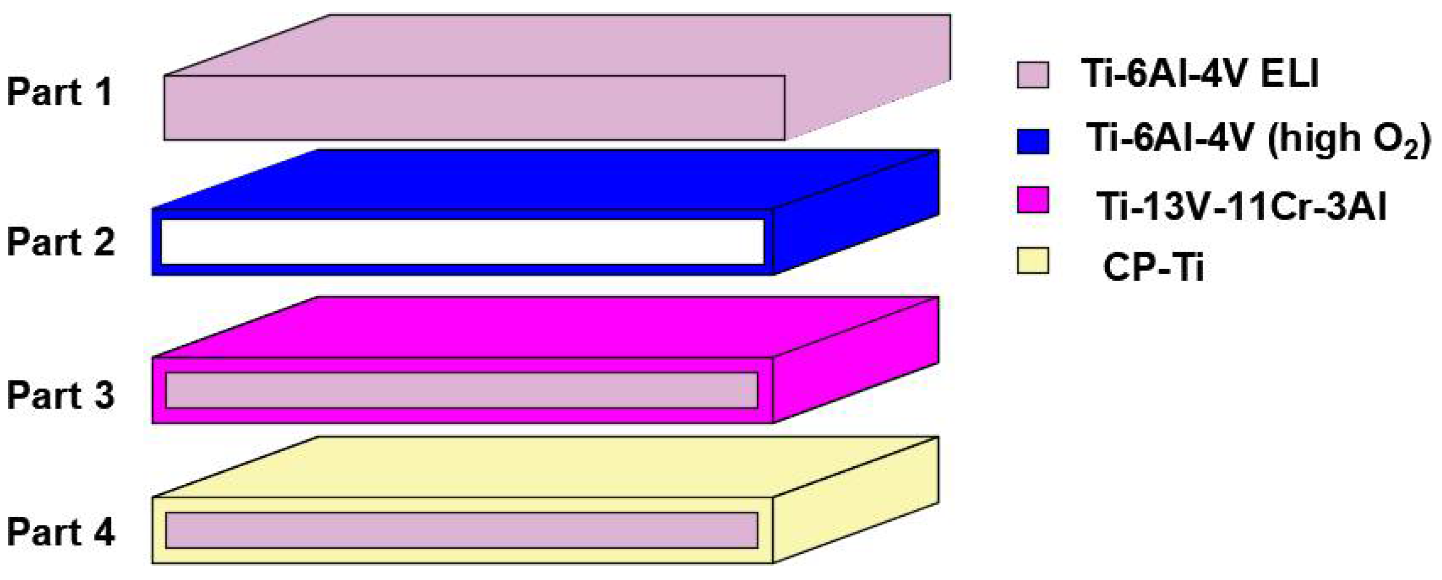
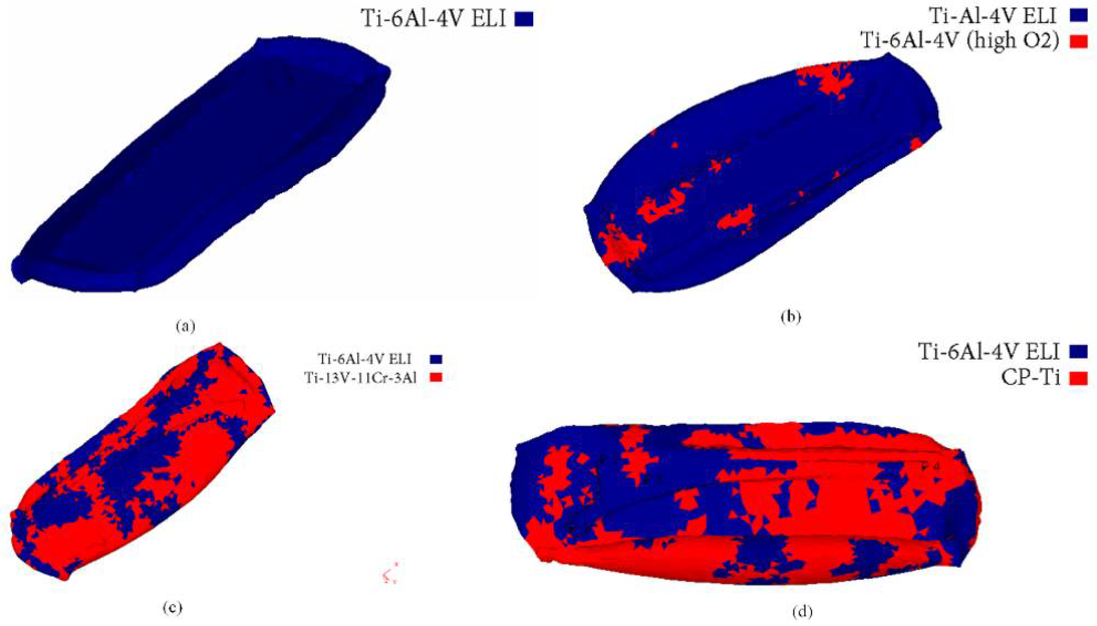
| Part | Description | Core | Shell |
|---|---|---|---|
| 1 | Single material | Ti-6Al-4V ELI | - |
| 2 | Core and Shell 1 | Ti-6Al-4V ELI | Ti-6Al-4V (high O2) |
| 3 | Core and Shell 2 | Ti-6Al-4V ELI | Ti-13V-11Cr-3Al |
| 4 | Core and Shell 3 | Ti-6Al-4V ELI | CP-Ti (commercially pure titanium) |
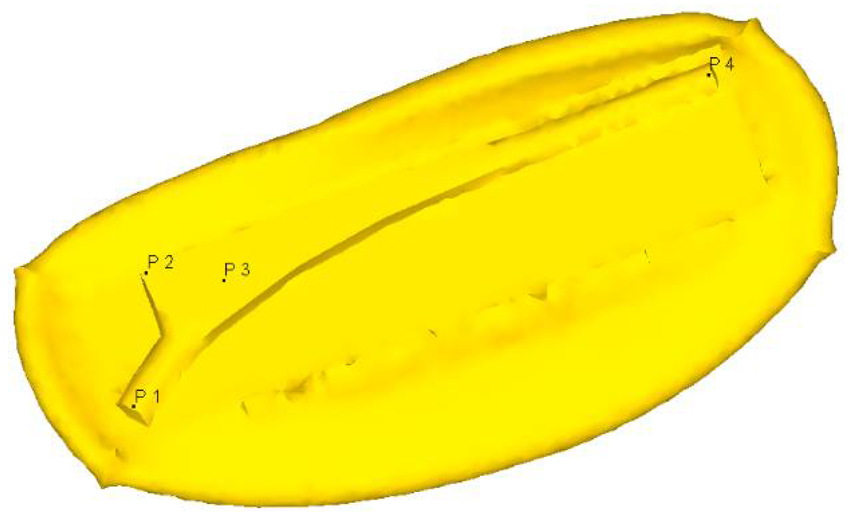
| S. No | Input Parameter | Output Parameter (at Four Points) |
|---|---|---|
| 1 | Billet dimensions | Temperature distribution |
| 2 | Four points were chosen on the surface of billet | Effective stress |
| 3 | Velocity of billet | Induced damage |
| 4 | Total distance moved by the two dies | Strain and velocity |
| 5 | Emissivity and convective heat transfer | - |
| 6 | Coefficient of heat transfer and friction coefficient between billet and die materials | - |
| 7 | The atmospheric temperature and initial temperature of billet materials | - |
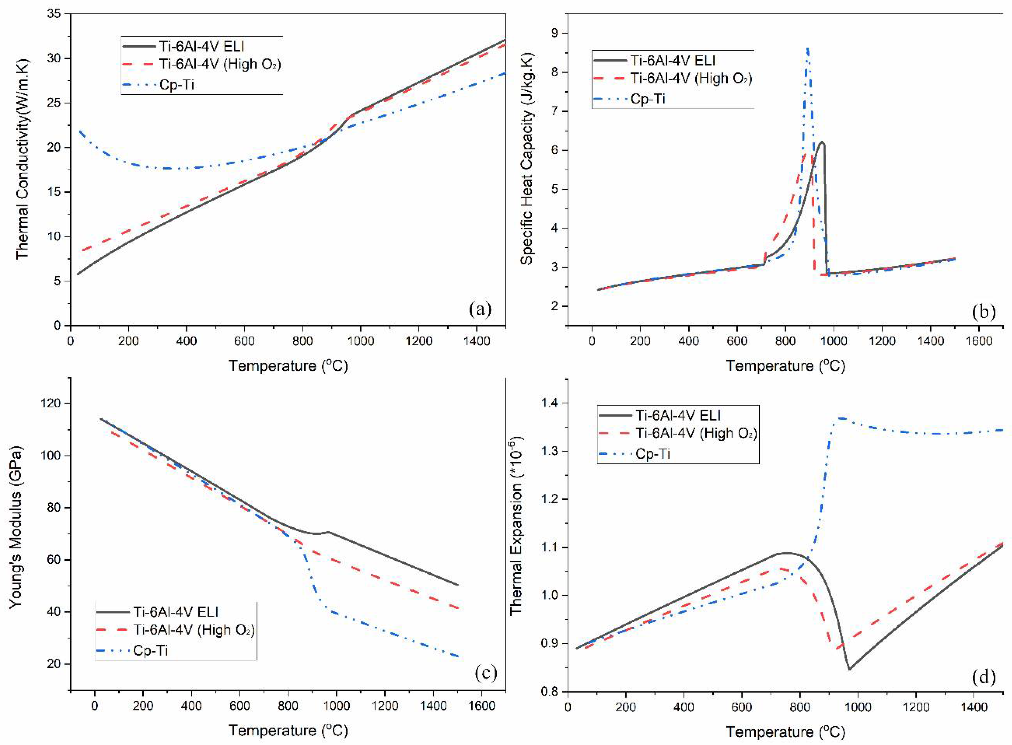
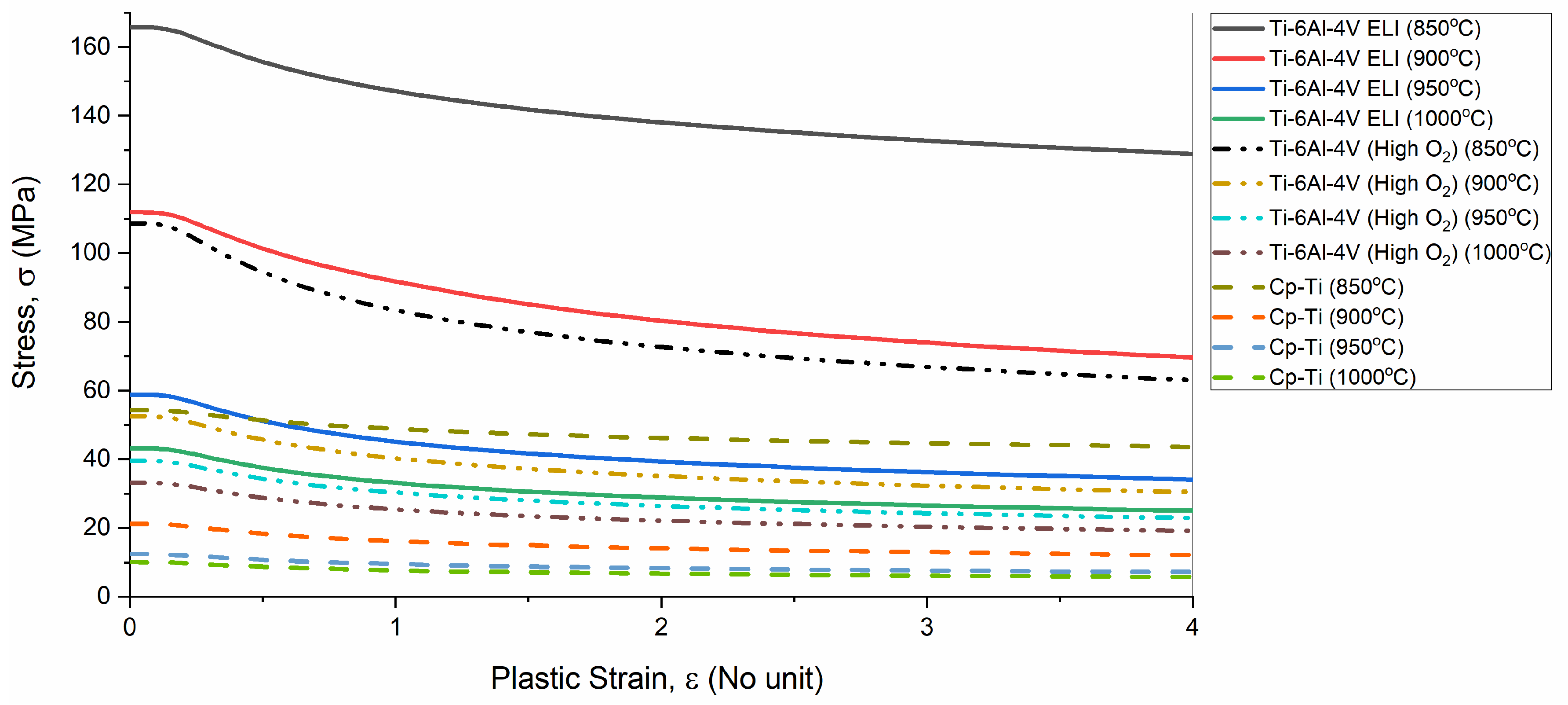
| 8 | Flow stress, Poisson’s ratio, specific heat, thermal conductivity, and Young’s modulus (Obtained from JMatPro software) | - |
Publisher’s Note: MDPI stays neutral with regard to jurisdictional claims in published maps and institutional affiliations. |
© 2022 by the authors. Licensee MDPI, Basel, Switzerland. This article is an open access article distributed under the terms and conditions of the Creative Commons Attribution (CC BY) license (https://creativecommons.org/licenses/by/4.0/).
Share and Cite
Raj, M.K.A.; Madheswaran, B.; Alrubaie, A.J.; Panchal, H.; Muthusamy, S.; Jaber, M.M.; Prakash, C.; Davim, J.P.; Saxena, K.K.; Buddhi, D. Effect of Titanium Based Alloys on Thermo-Mechanical Behavior in 3D Forging Simulation. Metals 2022, 12, 1611. https://doi.org/10.3390/met12101611
Raj MKA, Madheswaran B, Alrubaie AJ, Panchal H, Muthusamy S, Jaber MM, Prakash C, Davim JP, Saxena KK, Buddhi D. Effect of Titanium Based Alloys on Thermo-Mechanical Behavior in 3D Forging Simulation. Metals. 2022; 12(10):1611. https://doi.org/10.3390/met12101611
Chicago/Turabian StyleRaj, Mohan Kumar Anand, Balaji Madheswaran, Ali Jawad Alrubaie, Hitesh Panchal, Suresh Muthusamy, Mustafa Musa Jaber, Chander Prakash, Joao Paulo Davim, Kuldeep Kumar Saxena, and Dharam Buddhi. 2022. "Effect of Titanium Based Alloys on Thermo-Mechanical Behavior in 3D Forging Simulation" Metals 12, no. 10: 1611. https://doi.org/10.3390/met12101611
APA StyleRaj, M. K. A., Madheswaran, B., Alrubaie, A. J., Panchal, H., Muthusamy, S., Jaber, M. M., Prakash, C., Davim, J. P., Saxena, K. K., & Buddhi, D. (2022). Effect of Titanium Based Alloys on Thermo-Mechanical Behavior in 3D Forging Simulation. Metals, 12(10), 1611. https://doi.org/10.3390/met12101611