Abstract
Fabrication of thick (more than 3 mm) hard coatings on Al-Mg alloys might provide better performance in terms of increased durability, wear resistance and hardness compared with the unmodified material. In this study we fabricated Al-Co-Cr-Fe-Mn-Ni high-entropy alloy coating by wire-arc additive manufacturing onto AA5083 substrate. The aim of this study is to investigate the microstructure and mechanical properties of the coating and its influence on the substrate. Scanning electron microscopy and transmission electron microscopy were used to characterize the microstructure and elemental composition of the obtained coating. Microhardness and tribological tests were implemented to evaluate the mechanical properties. The results showed homogeneous distribution of the elements alongside the transversal direction in the coating which has the following average chemical composition: Al 8 at. %, Co 28 at. %, Cr 13 at. %, Fe 33 at. %, Mn 3 at. %, Ni 15 at. %. The wear rate of the coating decreased by ~five times comparing with the substrate, while the Vickers hardness improved by ~three times. The highest level of hardness accounting for 1010 ± 80 HV was observed in the transition zone between the coating and the substrate which might be attributed to high micro- and macrostress levels appeared in this zone. The study showed the practical applicability of wire-arc additive manufacturing method to fabricate a high-entropy alloy on Al-Mg substrate.
1. Introduction
The modern requirements for production in transportation industries are constantly growing, due to the concerns for environmental protection and reducing greenhouse gas emissions. Decreasing the weight of components is capable of reducing fuel consumption and corresponding emissions because the lower the weight, the less energy is required to move a vehicle [1]. Therefore, replacing steel components onto lightweight materials, such as aluminum and magnesium alloys, or composites, is a crucial task for scientists and engineers around the globe [2].
The main issue in the weight reduction is to retain the strength, durability, and other performance properties of machine parts. While aluminum alloys exhibit low density, high strength to weight ratio, good corrosion resistance and relatively low cost, they suffer from low wear resistance, as well as low hardness which restricts their applications [3].
In general, increasing the hardness of a material can be achieved by incorporating obstacles in the microstructure which hinder movement of dislocations. Such obstacles can be other dislocations, grain boundaries, solute atoms, and particles of another phase [4]. However, some of Al alloys are non-heat-treatable, so their possible improvements are limited only by surface modifications or work hardening.
There are several techniques which work well to fabricate hard coatings on Al alloys: hard anodizing [5], physical vapor deposition [6], thermal spraying of hard coatings [7], plasma electrolytic oxidation [8], and laser cladding [9]. For example, Al2O3 coating deposited by hard anodizing on AA6063 exhibited enlarged hardness by 5.7 times [5]. Laser cladding of Ni-WC coating onto AA5083 increases hardness of the alloy by about 12 times, while wear resistance rises by 2.5 times [10]. Cold spray deposited WC-CoCr coating followed by friction stir processing reinforced AA5083 matrix and increased the average hardness by 540% over the as-casted alloy [11].
Although the above-mentioned methods exhibit excellent improvements in hardness, they are only capable of fabricating a single-passed coating with limited thickness up to 3 mm. However, thicker coatings can provide better performance and life to resist high loading, heat conduction, corrosion, and oxidation in severe environments [12]. In addition, technologies such as physical vapor deposition or thermal spraying have low deposition rates and restricted areas of deposition which might not be efficient for industrial capacities. Therefore, development of a technology that might overcome these drawbacks for improving hardness and wear resistance of non-heat-treatable aluminum alloys is a tricky but significant task.
Weld overlay cladding is a well-known technique in gas and mining industries that can provide thick coatings (up to 6 mm) by joining via welding a protection material to a base metal. This method is cost-effective because the deposition occurs at high rates (up to 8 kg/h) and the feeding material is a wire which is mainly cheaper than the powder used, for example, in laser cladding or thermal spraying [13]. In addition, the implementation of a robot, as in wire-arc additive manufacturing, allows for the fabrication of coatings onto a complex geometry surface, which broadens the possible usage of this technique [14]. The recent results showed the possibility of weld overlaying by cold metal transfer technique of Al-Si-Mn coating with the thickness greater than 2.5 mm in a single pass onto 3 mm pure-aluminum plate [15]. The coating demonstrated good metallurgical bonding with the substrate due to partial melting of the substrate; however, the hardness of the Al-Si-Mn coating was not more than 60 HV which is much lower than in those hard coatings from the studies considered above.
Recent reports demonstrated an applicability of wire-arc additive manufacturing technology for producing high-entropy alloys. High-entropy alloys (HEAs) composed of more than five principal components varying from 5 to 35 at. % and exhibit good tribological characteristics, relatively high hardness, as well as good strength-to-plasticity balance at room, cryogenic, and elevated temperatures [16]. These properties are possible in HEAs due to the effects of high entropy of mixing, sluggish diffusion, and severe strain that are possible because of their unique chemical compositions [16]. Chen X. et al. fabricated bulk Al-Co-Cr-Fe-Ni HEAs by twisting seven wires in a cable-type wire and melting them using a cold metal-transfer intelligent-arc additive manufacturing system [17,18]. The results showed a relatively high hardness (350 HV) and high tensile strength (916 MPa to 1087 MPa) of the manufactured alloys. Liu J. et al. fabricated a single layer onto Ti-6Al-4V substrate by weld overlaying of MoNbTaWTi HEA and revealed high hardness at room temperature (533 HV0.2) and at 1000 °C (110 HV1) [19]. In our previous studies, we showed that non-equiatomic Co-Cr-Fe-Mn-Ni HEA fabricated via WAAM has a relatively high yield strength ~279 MPa and strain before fracture (~63%), compared with the alloys fabricated by arc melting [20,21]. The addition of Al to Co, Cr, Fe, Mn, and Ni leads to the formation of different phases from single FCC, duplex FCC + BCC to single BCC phase, as well as the increased microhardness and reduced corrosion resistance [22]. This indicates that Co-Cr-Fe-Mn-Ni HEA has the potential to improve the surface properties of Al substrates [23].
Wire-arc additive manufacturing is a promising technology, but it has not yet been applied to fabricate high-entropy alloy coatings. Since HEA coatings obtained by other methods revealed excellent mechanical properties, such as high hardness, wear, corrosion resistance, etc., a study of the application of wire-arc additive manufacturing to weld overlay HEA coatings can greatly expand this field and lay the groundwork for future research. Additionally, aluminum alloys coated with high-entropy materials may be useful in the automobile or aerospace industries, where a proper strength-to-weight-ratio is required.
Taking into account the above-mentioned background, the aim of this study was to fabricate an Al-Co-Cr-Fe-Mn-Ni HEA coating onto non-heat-treatable AA5083 substrate. Hardness and tribological tests were used to evaluate its mechanical performance, as well as scanning and transmission electron microscopy which were carried out to investigate the microstructure and distribution of chemical elements. The results showed that the coating is harder than the substrate by ~three times and has higher wear resistance by ~five times.
2. Materials and Methods
AA5083 plate with the chemical composition (wt. %) of 4.4–4.8 Mg, 0.05–0.15 Cr, 0.6–0.9 Mn, 0.1 Cu, 0.25 Zn, 0.15 Ti, 0.4 Fe, 0.4 Si, and Al—balanced (according to ASTM B209) and a size of 350 mm × 350 mm × 5 mm was selected as a substrate. The surface of the substrate was hand-held grinding wheel ground until the surface showed a metallic luster.
According to the previous studies, the following wires were selected for stranding into a cable-type wire: 99.9 at. % Co wire with the diameter of 0.47 mm; Autrod 16.95 welding wire contained (at. %) of 65.3 Fe, 19.6 Cr, 7.3 Ni, 1.6 Si, 6.2 Mn, with the diameter of 0.7 mm; Ni80Cr20 wire contained (at. %) of 22.5 Cr, 1.5 Fe, 72.1 Ni, 0.8 Al, 2.9 Si, 0.2 Mn, with the diameter of 0.4 mm [20]. The wires were stranded using special stranding equipment. The average diameter of the combined cable wire was 1.2 mm, with a lay length of 10 mm.
To deposit a single-layer coating, we used a metal inert gas (MIG) TECH MIG 250 (Svarog, Saint-Petersburg, Russia) automated with Anycubic Chiron (Shenzhen Anycubic Technology Co., Ltd., Shenzhen, China) setup with the following parameters of overlay cladding: wire feed speed 10 m/min; amperage ~100 A; voltage 22 V; inductance 3 H; travel speed 200; layer length of 100 mm. The gun moved with the drag travel angle of 10°. Argon (99.99%) was used as a shielding gas.
The scanning electron microscopy (SEM) of the cross-sectional view of the obtained samples was performed using LEO EVO 50 (ZEISS, Oberkochen, Germany) and energy-dispersive X-ray spectroscopy (EDS) conducted using INCA Energy (Oxford Instruments, Oxford, UK). The defect sub-structure and distribution of chemical elements were studied using transmission electron microscopy (TEM) (JEM-2100 instrument, JEOL, Tokyo, Japan with an EM-24511SIOD STEM attachment). Microhardness tests were carried by a Vickers microhardness tester HVS-1000 (Time Group Inc., Bejing, China) with the indenter load of 0.5 N and dwell time of 10 s.
X-ray diffraction analysis was performed using X-ray diffractometer Shimadzu XRD 6000 (Shimadzu, Kyoto, Japan) with Cu-Kα (λ = 0.154 nm) radiation at a step of 0.02°, voltage 40 kV, current 30 mA, and scan speed 2 deg/min.
Wear testing was performed using ball-on-disk Oscillating TRIBOtester (TRIBOtechnic, Clichy, France) with a 6 mm diameter WC ball against the flat coating sample. The tests were executed at room temperature with the following parameters: sliding speed 25 mm/s; sliding length 50 m; normal load of 2 N; wear track radius of 2 mm; and humidity of 50% r.H.
3. Results and Discussion
Figure 1a shows a fragment of the Al-Co-Cr-Fe-Mn-Ni high-entropy alloy coating fabricated via gas-metal arc welding. The microstructure of the coating represents various areas with the different tonality: darker and brighter, which might be attributed to the inhomogeneous content of the chemical elements in these local regions and, correspondingly, different phases. The overall chemical composition of the coating is quite uniform, according to Figure 1b. The standard deviation from the average content of each component is not more than 1.4% (for Al which reveals the highest deviation). This might be related to not complete solid solubility of the main element of the substrate in the crystal lattice of the coating. The amount of Al atoms increases when approaching the substrate, and in the beginning of the transition zone between the coating and the substrate reaches its maximum value of 32 at. % (Figure 1d). After the distance of 160 µm, its value sharply drops down to 11 at. %, and gradually increases as the distance from the transition zone increases. The concentrations of Fe and Co slightly rise at 160 µm and after this distance steadily decrease with the following completely disappearing at 730 µm.
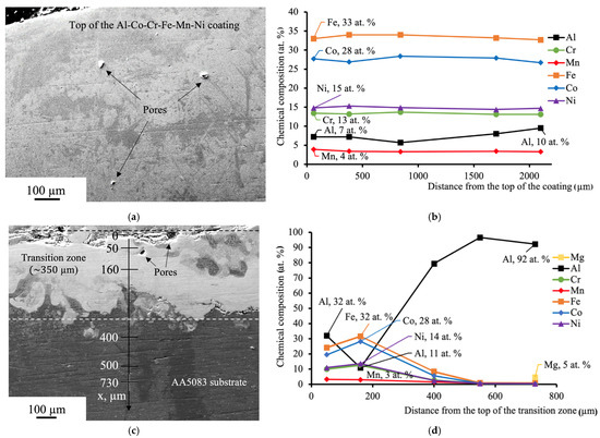
Figure 1.
(a) SEM of the Al-Co-Cr-Fe-Mn-Ni HEA coating; (b) the results of EDS analysis accomplished from the top of the coating; (c) SEM of the transition zone between the coating and the substrate. The distances from the top of the transition zone in which EDS analysis was carried out are marked on the axis; (d) the results of EDS analysis alongside the axis indicated in (c).
The coating and the area in transition zone adjacent to the coating have pores with the size of 29 ± 10 µm. These defects might occur due to the chemical reactions or, possibly, because not all gas molecules had the opportunity to escape the overlayed area before the metal cooled and solidified [24].
The XRD pattern of the Al-Co-Cr-Fe-Mn-Ni HEA coating is shown in Figure 2. The coating has a dual phase structure: 81.8% FCC (Fm-3m space group) with the lattice parameter a = 0.3637 nm and 18.2% AlFe (Pm-3m space group) with the lattice parameter a = 0.28813 nm. According to these percentages, a dark-gray region in Figure 1 evidently represents the AlFe phase, whereas a light-gray region is FCC. FCC reflections have indices 111, 200, and 220 at the 2Θ values of 43.99°, 51.19°, 75.16°, and the crystalline size of 12.07 nm. The crystalline size of the AlFe phase is 27.77 nm and reflections have indices 110, 200, and 211 at the 2Θ values of 43.99°, 64.42°, and 81.64°. The results of the XRD analysis reveal that atoms of Al diffused from the substrate during weld overlay and mixed with the atoms of other elements forming the AlFe phase. It is also approved by the fact that the cable-type wire with the same chemical composition melted without influence of Al substrate forms a single FCC phase [20]. The lattice parameter of the FCC phase of Co-Cr-Fe-Mn-Ni HEA obtained by WAAM (a = 0.35788 nm) is smaller than that of the FCC phase of Al-Co-Cr-Fe-Mn-Ni coating by 1.6% [20]. This might indicate a small increase in the lattice strain related to the substitution of Al atoms.
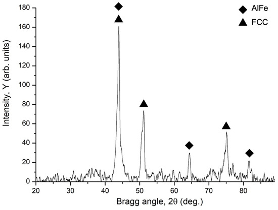
Figure 2.
X-ray diffraction pattern of Al-Co-Cr-Fe-Mn-Ni coating fabricated by WAAM onto AA5083 substrate.
The bottom part of the transition zone has a uniform structure and on closer consideration reveals two distinct microstructures: (a) relatively homogeneous one (regions with light-gray tonality) (b) and second-phase precipitations with the size of 14 ± 2 µm (c) (Figure 3a). The elemental mapping in Figure 3b shows that the phase with light-gray tonality is comprised of the elements of the coating dissolved quite homogeneously in Al and distinct areas enriched with Mg, while precipitations having the same elements, except for Ni, form a needle-shaped morphology.
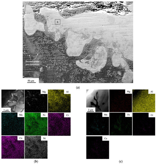
Figure 3.
(a) SEM of the transition zone between the Al-Co-Cr-Fe-Mn-Ni coating and the AA5083 substrate, (b) TEM bright-field image and the elemental mapping of the area (b) indicated in (a), (c) TEM bright-field image and the elemental mapping of the area (c) indicated in (a).
The quantitative data of the chemical composition of these two regions are presented in Table 1. The main components of the light-gray region are Al, Fe, and Co. TEM-selected area diffraction proved in Figure 4a–c shows that this area consists of Al3Ni second-phase precipitates. The second-phase precipitate has the crystal structure of Al13Fe4.

Table 1.
Chemical composition of second-phase precipitations in the transition zone (at. %).
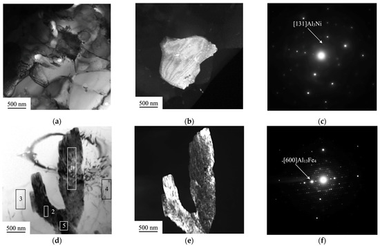
Figure 4.
(a) TEM bright-field image of the light-gray area indicated in Figure 2; (b) TEM dark-field image of the second-phase particle Al3Ni; (c) Selected area diffraction pattern originating from the crystal oriented with [131]; (d) TEM bright-field image of a second-phase precipitation; the numbers indicate areas from which an elemental analysis was made; (e) TEM dark-field image of the second-phase precipitation Al13Fe4; (f) selected area diffraction pattern originating from the crystal oriented with [600].
The areas 3 and 4 in Table 2 consist of Al and Mg and represent the substrate of AA5083. The areas indicated as 1, 2, and 5 besides the atoms of the substrate are enriched with the elements of the coating. The precipitations of the morphology could be formed upon cooling of the melted layer adjacent to the substrate. Since Al-Mg alloy has the melting temperature (in the range of 580–640 °C) lower than the feeding wire composed of Co-Cr-Fe-Mn-Ni (around 1430–1440 °C [25]), nucleation of the atoms of the coating occurs first in the liquid phase of the Al-Mg composition. The process of nucleation in the area near to the substrate conveys probably within the higher thermal gradients (undercooling) than in those regions further from the substrate [26]. Therefore, the second-phase precipitates which are located at the bottom of the transition zone have a needle-shaped morphology oriented alongside the multiple directions of the temperature gradients.
Table 2.
The chemical compositions of the various areas in the Al13Fe4 second-phase precipitation which are indicated in Figure 3d (at. %).
The thickness of the obtained coating is around 4.5 mm; its average Vickers hardness equals to 294 ± 53 HV (Figure 5a), which is higher than the hardness of the substrate by three times. Comparing to the cast Al0.5CoCrFeMnN alloy [22] whose hardness is 175 HV, the hardness of the coating obtained in this study is relatively higher (by about 1.7 times); however, it is by about 1.2 times less than in the conventionally sintered Al0.5CoCrFeMnNi HEA, which is probably due to the higher density of the sample, attributed to the simultaneous combination of pressure and temperature during the compaction of the powders [27].
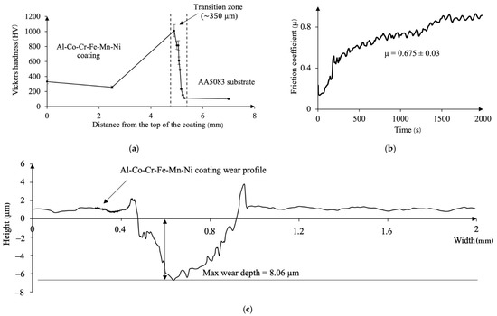
Figure 5.
(a) Variations of Vickers hardness values across the coating and the substrate; (b) evolution of friction coefficient of the Al-Co-Cr-Fe-Mn-Ni coating during the test duration; (c) wear profile of Al-Co-Cr-Fe-Mn-Ni coating after tribological test.
In the area adjacent to the coating, the hardness of Al-Co-Cr-Fe-Mn-Ni reaches the highest value of 1010 ± 80 HV. This value is comparable with the Vickers hardness of Al1.5CoCrFeMnNi HEA fabricated by high-frequency induction heat sintering (HFIHS) (830 HV0.3) because the samples sintered using the HFIHS method exhibit higher densification than the conventional sintering [27].
Then, as the distance from the beginning of the transition zone into the depth of the sample increases, the hardness rapidly drops down to 232 ± 9 HV and levels to the values of the substrate of 107 ± 8 HV.
The average friction coefficient of the Al-Co-Cr-Fe-Mn-Ni coating is 0.675 (Figure 5b). From the beginning of the wear test, the friction coefficient gradually increases from 0.2 to 0.3 during 230 s. Then, it rises sharply up to 0.5 and continually grades until the end of the test, up to 0.8. Such behavior of a friction coefficient might be related to the different wear mechanisms occurring during the tribological test. In the first stage (up to 230 s), between the counter-body and the surface of the coating, a sliding occurs without direct interaction because thin surface layers of oxide act as lubricant. Then, the mechanism changes, when the surface films break up faster than they can reform, increasing the wear rate, and the friction coefficient [28].
The wear rate of the coating was calculated according to the W = mm3/N·m formula, where mm3 refers to wear volume and N·m is normal load per sliding distance. According to the results of four profiles, including that presented in (Figure 5c), the wear rate of the coating is amounted to 7.3 × 10⁻⁵ mm3/N·m, which is ~five times higher than that the AA5083 substrate (3.5 × 10⁻⁴ mm3/N·m) and comparable with the wear rates of Al0.5CrFeCoNiCu HEA (9.4 × 10⁻⁵ mm3/N·m) obtained in [23].
The increased hardness value might be explained by aligning it with the results of EDS analysis presented in Figure 1 and with the results of the microstructure investigations presented in Figure 3 and Figure 4. The highest hardness corresponds to the region in the transition zone with the highest Al content (32 at. %) (Figure 1d) which usually promotes formation of a harder BCC phase [22]. The presence of the second-phase precipitates of Al3Ni revealed in Figure 4b might also contribute to the mechanism of hardening. During solidification, a super-saturated liquid solution decomposes into the second-phase precipitates inducing the development of residual microstress fields as the consequence of the volume misfit between the precipitates and the matrix [4]. In addition, since the linear coefficient of thermal expansion of the overlay (the equiatomic CoCrFeMnNi HEA has CTE 15 × 10−6 K−1 at room temperature [29]) is smaller than that of the AA5083 substrate (23.8 × 10⁻⁶ K−1) upon cooling it might induce the appearance of the residual compressive macrostress fields and the corresponding increase in the scalar density of dislocations equaling to (0.8–1.0) × 1010 cm−2 (Figure 6).
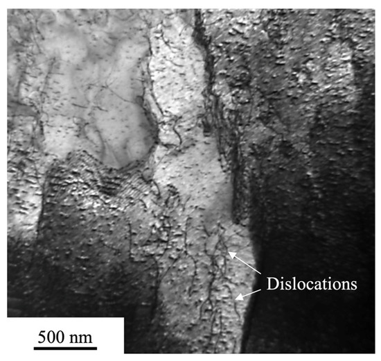
Figure 6.
TEM image of dislocations’ distribution in the transition zone.
To sum up, the increase in the hardness values as well as in wear resistance are probably attributed to micro- and macrostress fields developed due to the formation of the second-phase precipitations and the difference between the coefficients of thermal expansion of the Al-Co-Cr-Fe-Mn-Ni HEA coating and the AA5083 substrate. Although the results obtained in this study have some limitations (the results of X-ray diffraction analysis of the coating and the transition zone are absent, as well as only one set of the welding parameters being represented), the results show an applicability of wire-arc additive manufacturing technique for fabrication of a thick high-entropy alloy coating on Al-Mg aluminum alloy. The future research might be concerned with a more thorough study of the influence of various parameters of the weld overlay process on the properties of the HEA coating fabricated via wire-arc additive manufacturing.
4. Conclusions
In this study we fabricated Al-Co-Cr-Fe-Mn-Ni high-entropy alloy 4.5 mm thick coating on the AA5083 substrate using wire-arc additive manufacturing. The following conclusions could be drawn:
- The obtained coating has a greater hardness (294 ± 53 HV) than that of the substrate (107 ± 7 HV) by ~three times. The highest hardness (1010 ± 80 HV) was observed in the transition zone between the coating and the substrate which might be explained by high micro- and macrostress fields induced by the difference between linear coefficients of thermal expansion of the coating and the substrate as well as the formation of precipitates;
- The coating has better wear resistance compared to the substrate: the wear resistance of the coating is higher by ~five times than that of the substrate. The tribological characteristics of the coating are comparable with the other HEAs of the similar system;
- The phase composition of the coating composed of 81.8% FCC and 18.2% AlFe phases with the lattice parameters of 0.3637 nm and 0.28813 nm, correspondingly;
- The chemical composition of the coating is quite homogeneous, while in the transition zone there are areas enriched with the Al atoms. TEM revealed a formation of Al3Ni second-phase precipitates in these regions;
- The second-phase precipitations of Al13Fe4 were observed under the transition zone. These particles have a needle-shaped morphology, which might be related to the nucleation process that occurred in this area because of high thermal gradients.
Author Contributions
Conceptualization, S.K. and Y.I.; methodology, S.K., S.V. and V.G.; formal analysis, Y.I., S.V. and I.P.; investigation, S.K., Y.I. and K.O.; resources, S.K. and V.G.; writing—original draft preparation, S.K., K.O. and Y.I.; writing—review and editing, S.K., Y.I., V.G., K.O., S.V. and I.P.; supervision, V.G.; project administration, S.K. and V.G.; funding acquisition, V.G. All authors have read and agreed to the published version of the manuscript.
Funding
The fabrication of the high-entropy alloy coating, microhardness analysis, and investigation of structure and elemental composition by electron microscopy methods were funded by Russian Science Foundation, grant number 20-19-00452. The study of the phase composition and analysis of the physical mechanisms responsible for the high values of the hardness in the transition zone between the coating and the substrate were funded by Russian Science Foundation, grant number 19-19-00183, https://rscf.ru/project/19-19-00183/ (accessed on 24 September 2022).
Institutional Review Board Statement
Not applicable.
Informed Consent Statement
Not applicable.
Data Availability Statement
Not applicable.
Conflicts of Interest
The authors declare no conflict of interest.
References
- Taub, A.I.; Luo, A.A. Advanced lightweight materials and manufacturing processes for automotive applications. MRS Bull. 2015, 40, 1045–1053. [Google Scholar] [CrossRef]
- Zheng, K.; Politis, D.J.; Wang, L.; Lin, J. A review on forming techniques for manufacturing lightweight complex—Shaped aluminium panel components. Int. J. Lightweight Mater. Manuf. 2018, 1, 55–80. [Google Scholar] [CrossRef]
- Benedyk, J.C. Aluminum alloys for lightweight automotive structures. In Materials, Design and Manufacturing for Lightweight Vehicles; Mallick Design and Manufacturing for Lightweight Vehicles; Mallick, P.K., Ed.; Elsevier: Amsterdam, The Netherlands, 2010; pp. 79–113. ISBN 978-1-84569-463-0. [Google Scholar]
- Mittemeijer, E.J. Fundamentals of Materials Science; Springer: Berlin/Heidelberg, Germany, 2011; ISBN 978-3-642-10499-2. [Google Scholar]
- Kumar, S.A.; Pradhan, S.; Raman, S.G.S.; Gnanamoorthy, R. Performance of alumina coatings prepared by hard anodizing, micro arc oxidation and detonation spray processes on Al-Mg-Si alloy under fretting wear loading. Proc. Inst. Mech. Eng. Part J J. Eng. Tribol. 2014, 228, 454–462. [Google Scholar] [CrossRef]
- Bashir, M.I.; Shafiq, M.; Naeem, M.; Zaka-ul-Islam, M.; Díaz-Guillén, J.C.; Lopez-Badillo, C.M.; Zakaullah, M. Enhanced surface properties of aluminum by PVD-tin coating combined with cathodic cage plasma nitriding. Surf. Coat. Technol. 2017, 327, 59–65. [Google Scholar] [CrossRef]
- Gibbons, G.J.; Hansell, R.G. Thermal-sprayed coatings on aluminium for mould tool protection and upgrade. J. Mater. Process. Technol. 2008, 204, 184–191. [Google Scholar] [CrossRef]
- Lu, X.; Mohedano, M.; Blawert, C.; Matykina, E.; Arrabal, R.; Kainer, K.U.; Zheludkevich, M.L. Plasma electrolytic oxidation coatings with particle additions—A review. Surf. Coat. Technol. 2016, 307, 1165–1182. [Google Scholar] [CrossRef]
- Quazi, M.M.; Fazal, M.A.; Haseeb, A.S.M.A.; Yusof, F.; Masjuki, H.H.; Arslan, A. Laser-based surface modifications of aluminum and its alloys. Crit. Rev. Solid State Mater. Sci. 2016, 41, 106–131. [Google Scholar] [CrossRef]
- Quazi, M.M.; Fazal, M.A.; Haseeb, A.S.M.A.; Yusof, F.; Masjuki, H.H.; Arslan, A. laser composite surfacing of ni-wc coating on aa5083 for enhancing tribomechanical properties. Tribol. Trans. 2017, 60, 249–259. [Google Scholar] [CrossRef]
- Peat, T.; Galloway, A.; Toumpis, A.; McNutt, P.; Iqbal, N. The erosion performance of cold spray deposited metal matrix composite coatings with subsequent friction stir processing. Appl. Surf. Sci. 2017, 396, 1635–1648. [Google Scholar] [CrossRef]
- Murty, B.S.; Ranganathan, S.; Yeh, J.W.; Bhattacharjee, P.P. High-Entropy Alloys; Elsevier: Amsterdam, The Netherlands, 2019; ISBN 9780128160671. [Google Scholar]
- Luchtenberg, P.; de Campos, P.T.; Soares, P.; Laurindo, C.A.H.; Maranho, O.; Torres, R.D. Effect of welding energy on the corrosion and tribological properties of duplex stainless steel weld overlay deposited by GMAW/CMT process. Surf. Coat. Technol. 2019, 375, 688–693. [Google Scholar] [CrossRef]
- Hu, Z.; Hua, L.; Qin, X.; Ni, M.; Liu, Z.; Liang, C. Region-based path planning method with all horizontal welding position for robotic curved layer wire and arc additive manufacturing. Robot. Comput. Integr. Manuf. 2022, 74, 102286. [Google Scholar] [CrossRef]
- Rajeev, G.P.; Kamaraj, M.; Bakshi, S.R. Al-Si-Mn alloy coating on aluminum substrate using cold metal transfer (CMT) welding technique. JOM 2014, 66, 1061–1067. [Google Scholar] [CrossRef]
- Miracle, D.B.; Senkov, O.N. A critical review of high entropy alloys and related concepts. Acta Mater. 2017, 122, 448–511. [Google Scholar] [CrossRef]
- Shen, Q.; Kong, X.; Chen, X. Fabrication of bulk Al-Co-Cr-Fe-Ni high-entropy alloy using combined cable wire arc additive manufacturing (CCW-AAM): Microstructure and mechanical properties. J. Mater. Sci. Technol. 2021, 74, 136–142. [Google Scholar] [CrossRef]
- Yao, X.; Peng, K.; Chen, X.; Jiang, F.; Wang, K.; Wang, Q. Microstructure and mechanical properties of dual wire-arc additive manufactured Al-Co-Cr-Fe-Ni high entropy alloy. Mater. Lett. 2022, 326, 132928. [Google Scholar] [CrossRef]
- Liu, J.; Li, J.; Du, X.; Tong, Y.; Wang, R.; He, D.; Cai, Z.; Wang, H. Microstructure and mechanical properties of wire arc additively manufactured MoNbTaWTi high entropy alloys. Materials 2021, 14, 4512. [Google Scholar] [CrossRef] [PubMed]
- Osintsev, K.; Konovalov, S.; Zaguliaev, D.; Ivanov, Y.; Gromov, V.; Panchenko, I. Investigation of Co-Cr-Fe-Mn-Ni non-equiatomic high-entropy alloy fabricated by wire arc additive manufacturing. Metals 2022, 12, 197. [Google Scholar] [CrossRef]
- Osintsev, K.A.; Konovalov, S.V.; Gromov, V.E.; Ivanov, Y.F.; Panchenko, I.A. Microstructure and mechanical properties of non-equiatomic Co25.4Cr15Fe37.9Mn3.5Ni16.8Si1.4 high-entropy alloy produced by wire-arc additive manufacturing. Mater. Lett. 2022, 312, 131675. [Google Scholar] [CrossRef]
- Li, M.; Zhang, Q.; Han, B.; Song, L.; Li, J.; Yang, J. Investigation on microstructure and properties of AlxCoCrFeMnNi high entropy alloys by ultrasonic impact treatment. J. Alloy. Compd. 2020, 816, 152626. [Google Scholar] [CrossRef]
- Li, Y.; Shi, Y. Microhardness, wear resistance, and corrosion resistance of alxcrfeconicu high-entropy alloy coatings on aluminum by laser cladding. Opt. Laser Technol. 2021, 134, 106632. [Google Scholar] [CrossRef]
- Zhu, C.; Tang, X.; He, Y.; Lu, F.; Cui, H. Characteristics and formation mechanism of sidewall pores in NG-GMAW of 5083 Al-alloy. J. Mater. Process. Technol. 2016, 238, 274–283. [Google Scholar] [CrossRef]
- Gutierrez, M.A.; Rodriguez, G.D.; Bozzolo, G.; Mosca, H.O. Melting temperature of cocrfenimn high-entropy alloys. Comput. Mater. Sci. 2018, 148, 69–75. [Google Scholar] [CrossRef]
- Dong, H.B.; Lee, P.D. Simulation of the columnar-to-equiaxed transition in directionally solidified Al-Cu alloys. Acta Mater. 2005, 53, 659–668. [Google Scholar] [CrossRef]
- Ruiz-Esparza-Rodríguez, M.A.; Garay-Reyes, C.G.; Mendoza-Duarte, J.M.; Estrada-Guel, I.; Hernández-Rivera, J.L.; Cruz-Rivera, J.J.; Gutiérrez-Castañeda, E.; González, S.; Garay-Tapia, A.M.; Martínez-Sánchez, R. Evaluation of high-frequency induction heat sintering and conventional sintering in AlxCoCrFeMnNi high-entropy alloys. J. Alloy. Compd. 2022, 910, 164780. [Google Scholar] [CrossRef]
- Neale, M.J. Wear Mechanisms. In Lubrication and Reliability Handbook; Elsevier: Amsterdam, The Netherlands, 2001; pp. 1–3. [Google Scholar]
- Laplanche, G.; Gadaud, P.; Horst, O.; Otto, F.; Eggeler, G.; George, E.P. Temperature dependencies of the elastic moduli and thermal expansion coefficient of an equiatomic, single-phase CoCrFeMnNi high-entropy alloy. J. Alloy. Compd. 2015, 623, 348–353. [Google Scholar] [CrossRef]
Publisher’s Note: MDPI stays neutral with regard to jurisdictional claims in published maps and institutional affiliations. |
© 2022 by the authors. Licensee MDPI, Basel, Switzerland. This article is an open access article distributed under the terms and conditions of the Creative Commons Attribution (CC BY) license (https://creativecommons.org/licenses/by/4.0/).