Review

Post-Processing Techniques to Enhance the Quality of Metallic Parts Produced by Additive Manufacturing

1
National Institute for Laser, Plasma and Radiation Physics (INFLPR), Ilfov, 077125 Magurele, Romania
2
Organize Sanayi Bölgesi, ERMAKSAN, 16065 Bursa, Turkey
3
Department of Mechanical Engineering, Gazi University, 06570 Ankara, Turkey
4
Additive Manufacturing Technologies Research and Application Center-EKTAM, Gazi University, 06560 Ankara, Turkey
5
Department of Industrial Engineering and Robotics, University Politehnica of Bucharest, 060042 Bucharest, Romania
*
Author to whom correspondence should be addressed.
Metals 2022, 12(1), 77; https://doi.org/10.3390/met12010077
Submission received: 8 October 2021 / Revised: 24 December 2021 / Accepted: 25 December 2021 / Published: 4 January 2022

Abstract

:
Additive manufacturing (AM) processes can produce three-dimensional (3D) near-net-shape parts based on computer-aided design (CAD) models. Compared to traditional manufacturing processes, AM processes can generate parts with intricate geometries, operational flexibility and reduced manufacturing time, thus saving time and money. On the other hand, AM processes face complex issues, including poor surface finish, unwanted microstructure phases, defects, wear tracks, reduced corrosion resistance and reduced fatigue life. These problems prevent AM parts from real-time operational applications. Post-processing techniques, including laser shock peening, laser polishing, conventional machining methods and thermal processes, are usually applied to resolve these issues. These processes have proved their capability to enhance the surface characteristics and physical and mechanical properties. In this study, various post-processing techniques and their implementations have been compiled. The effect of post-processing techniques on additively manufactured parts has been discussed. It was found that laser shock peening (LSP) can cause severe strain rate generation, especially in thinner components. LSP can control the surface regularities and local grain refinement, thus elevating the hardness value. Laser polishing (LP) can reduce surface roughness up to 95% and increase hardness, collectively, compared to the as-built parts. Conventional machining processes enhance surface quality; however, their influence on hardness has not been proved yet. Thermal post-processing techniques are applied to eliminate porosity up to 99.99%, increase corrosion resistance, and finally, the mechanical properties’ elevation. For future perspectives, to prescribe a particular post-processing technique for specific defects, standardization is necessary. This study provides a detailed overview of the post-processing techniques applied to enhance the mechanical and physical properties of AM-ed parts. A particular method can be chosen based on one’s requirements.

1. Introduction

Additive manufacturing (AM), commonly designated as three-dimensional (3D) printing or rapid prototyping, generates 3D objects in a layer-wise manner based on a computer-aided design model [1]. AM has experienced significant changes in production principle, feedstock, and part performance [2]. AM can rapidly generate 3D complicated structural elements based on the process characteristics of point-by-point melting and layer-by-layer manufacturing [3]. The non-equilibrium solidification process may be tweaked to produce parts having particular properties for special applications [4]. AM has various advantages, including a short manufacturing cycle and reasonable manufacturing cost in mini-batches [5]. This technology produces parts using merely raw materials and equipment, thus eliminating the prerequisite of sophisticated tooling or molds, resulting in significant processing and assembly time savings. Near-net-part generation, tiny machining allowance and excellent material utilization are also advantages of AM processes [6]. In AM, the laser energy density is sufficient to process a wide range of materials [7]. Because of the high energy density of the laser beam, it can effectively elevate the localized thermal distribution to thousands of degrees, which is enough to melt the majority of metal materials. The AM metallic parts contain substantial residual stresses compared to conventional casting methods [8]. The layer-by-layer printing method releases the “forming” stress when the deposited layer solidifies. On the other hand, AM processes have numerous advantages, including the capacity to produce a variety of multi-material composites [9], high processing efficiency and manufacturing of various complicated structures [10].
However, due to layer-by-layer deposition, the surface quality of AM parts is typically inferior compared with the conventional manufacturing processes, which is a significant concern in AM processes [11]. Surface roughness usually varies depending on the AM technique. As a result, AM alone cannot simultaneously produce parts that meet both mechanical and surface roughness requirements [12]. In most cases, the most influencing aspect is the lack of process dynamics comprehension. Due to the sophisticated metallurgical and thermo-physical phenomena, the interaction mechanisms between the powder bed and the melt-pool, the powder bed and laser beam, and the melting processes are challenging to explain in the case of laser additive manufacturing (LAM) procedures. For instance, in the case of selective laser melting (SLM), the intense bonding force in processing zones and the quick solidification phenomenon under an ultra-high temperature gradient must be evaluated. Research is needed to evolve the parts’ internal structure and thermal stress changes under cyclic heating and cooling. During AM, internal faults such as balling effect, pores formation, cracks generation, powder aggregation, and thermal stresses are usually generated. These flaws significantly impact the manufactured product microstructure and structural mechanics [13]. As a result, post-processing techniques are frequently needed after the parts are printed to improve mechanical characteristics and surface quality, thus allowing them to be used as intended [14]. Many post-processing techniques are available, including thermal post-processing to reduce thermally-induced residual stresses. Laser peening is usually applied to lessen micro-defects and to improve surface quality.
This review article discusses the effect of laser peening and polishing, machining, thermal post-processing, and abrasive finishing techniques on AM parts. Section 2 collects the classification of various AM available as per ISO-ASTM 59200 (2015) standard. Section 3 discusses the primary defects, including porosity formation, cracks formation, anisotropy and surface roughness problems in the AM-ed parts. Based on the literature review, the cause of these issues has also been highlighted in Section 3. For Section 4, laser shock peening (LSP), Laser polishing (LP), conventional machining process (CMP), including milling, rolling and chemical and abrasive machining, and heating processes (HP) containing solution heat treatment (SHT), hot isostatic pressing (HIP) and T6-heat treatment (T6-HT). Furthermore, their effects on the AM-ed parts have been highlighted. Moreover, the post-processing techniques’ future outlook and conclusion have been provided in Section 5.

2. Classification of Additive Manufacturing (AM) Processes

According to ISO-ASTM 52900 (2015), AM is a procedure to join materials, layer-by-layer, to generate three-dimensional parts [15]. In recent years, AM applications have been expanded into several industrial sectors due to the technology providing opportunities for improved functionality, productivity, and competitiveness. Metal AM has unlimited potential and has recently been explored in the medical, aerospace and automotive industries [16]. On the one hand, products with complex geometry, operational flexibility, and reduced manufacturing time can be produced using AM methods. On the other hand, they face several difficulties: poor surface finish, undesirable microstructure phases, porosity and flaws, delamination, wear tracks, a lack of hardness and corrosion resistance, and decreased fatigue life. Parts made using AM suffer due to the issues mentioned above, reducing their mechanical and physical characteristics. Post-processing methods such as laser shock peening, laser polishing, conventional machining processes and heat treatments are often used to fix these problems. These methods can improve the surface characteristics and physical and mechanical properties. The following Section 2.1, Section 2.2, Section 2.3, Section 2.4, Section 2.5, Section 2.6 and Section 2.7, discuss the schematics of AM processes.

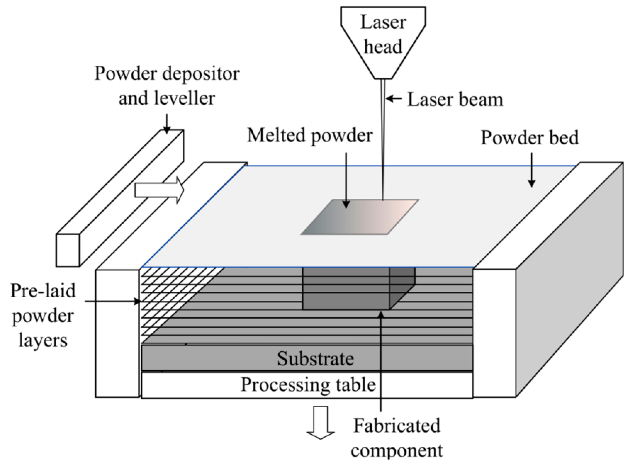
2.1. Powder Bed Fusion Process

High-energy power sources are used to selectively melt or sinter a metallic powder bed in the powder bed fusion (PBF) process. Figure 1 depicts a schematic representation of the PBF setup [17]. The laser beam goes through a series of lenses and is reflected onto the platform surface by a mirror. Mirrors direct the laser beam spot movement along with the pre-determined routes. The platform travels downward after a layer of powder is selectively melted. Following on, a recoating blade spreads another layer of powder from the powder dispenser at the top of the previously deposited layer, and the laser scanning process is repeated. The chamber is often filled with an inert gas such as argon [18].

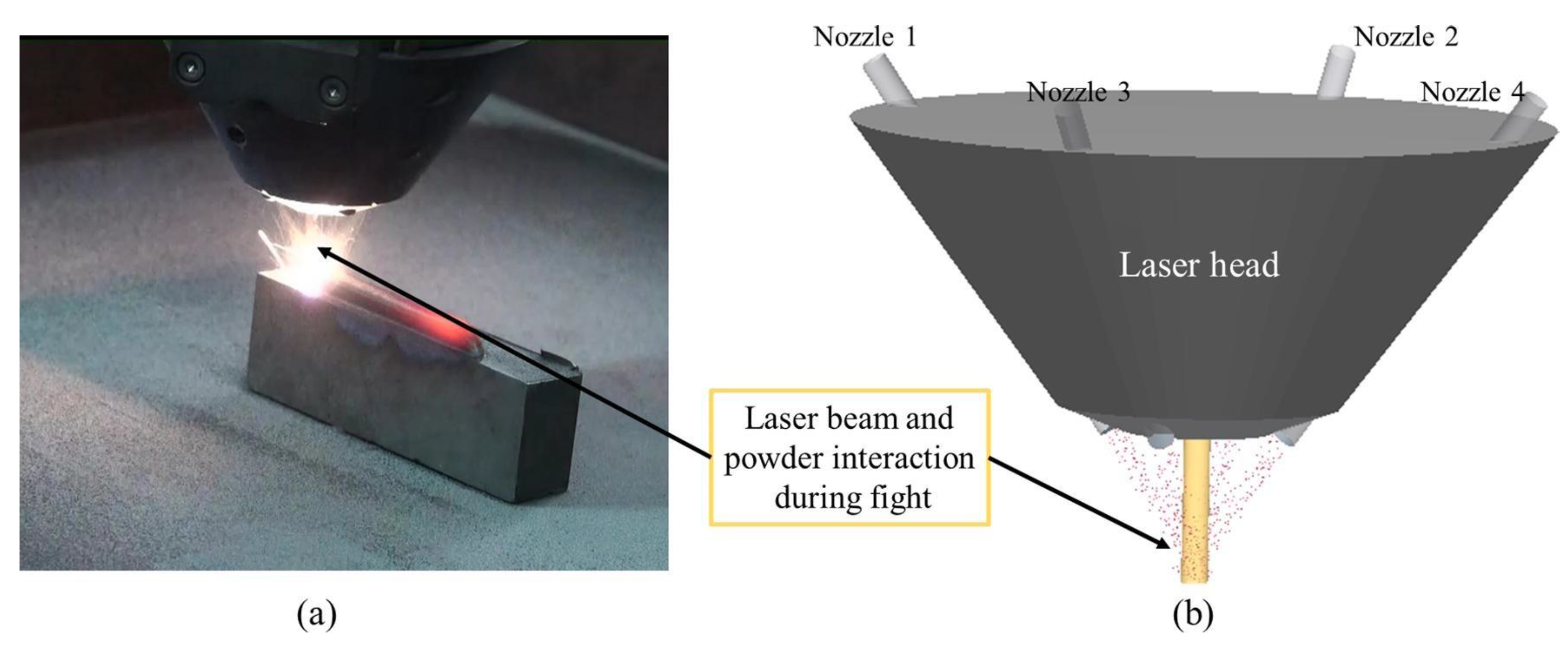
2.2. Direct Energy Deposition

The direct energy deposition (DED) schematic is presented in Figure 2 [19]. A laser, electron beam, or plasma arc can generate heat. Metallic powder or wire is the raw material to produce final products. Compared to metallic wires, powders have a poorer deposition efficiency because only a portion of the entire powder is melted and deposited into the substrate. Typical powder DED machines incorporate an inert gas blasted out of the nozzle along with the powder, shielding the melted area from oxidation [20].

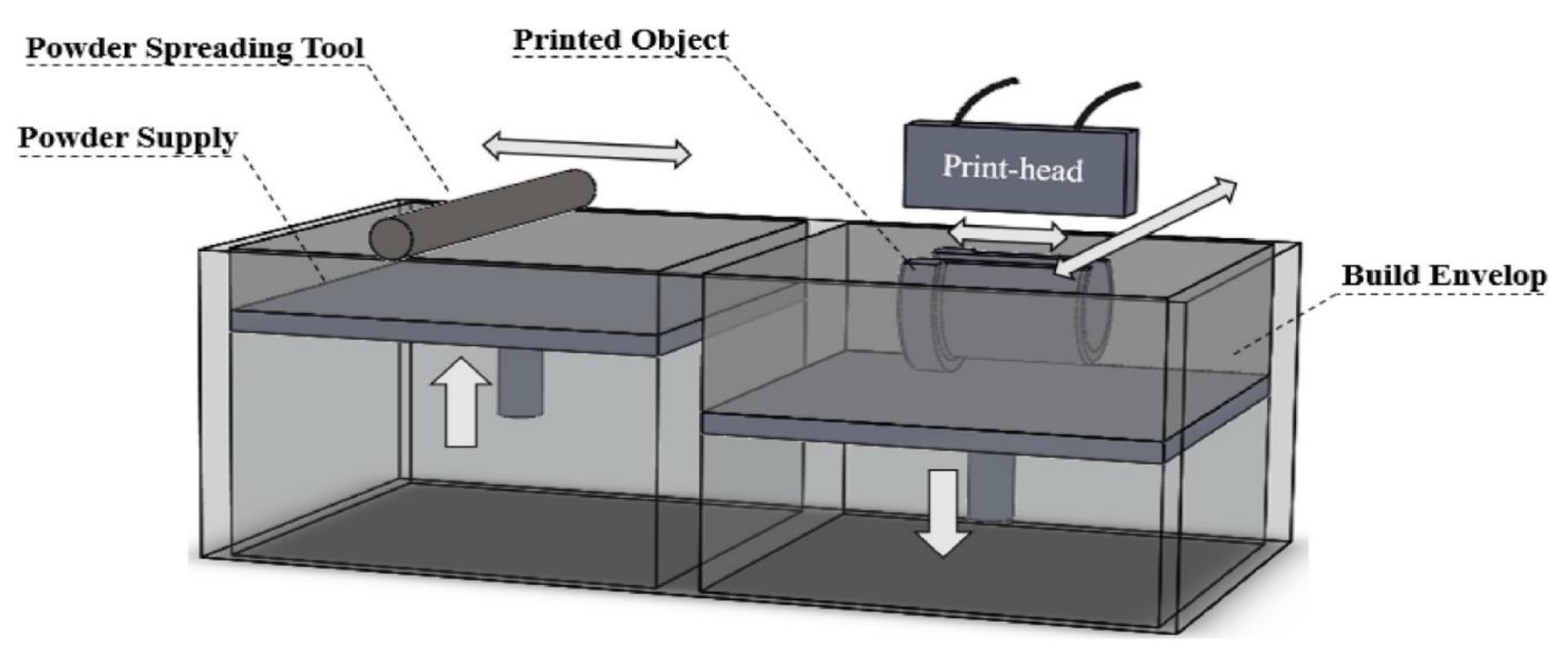
2.3. Binder Jetting Process

Figure 3 shows the schematic of the Binder jetting process [21]. A layer of powder is spread via a counterrotating roller for each layer. An inkjet print-head then pours/flows the liquid binding agent onto the powder bed to form a layer. Heaters may be used in some binder/powder systems to manage moisture and curing, but heat is not a necessary process requirement. After each layer, the build platform is lowered to print the next layer. The printed items are often brittle and require post-processing to improve the mechanical characteristics [21].

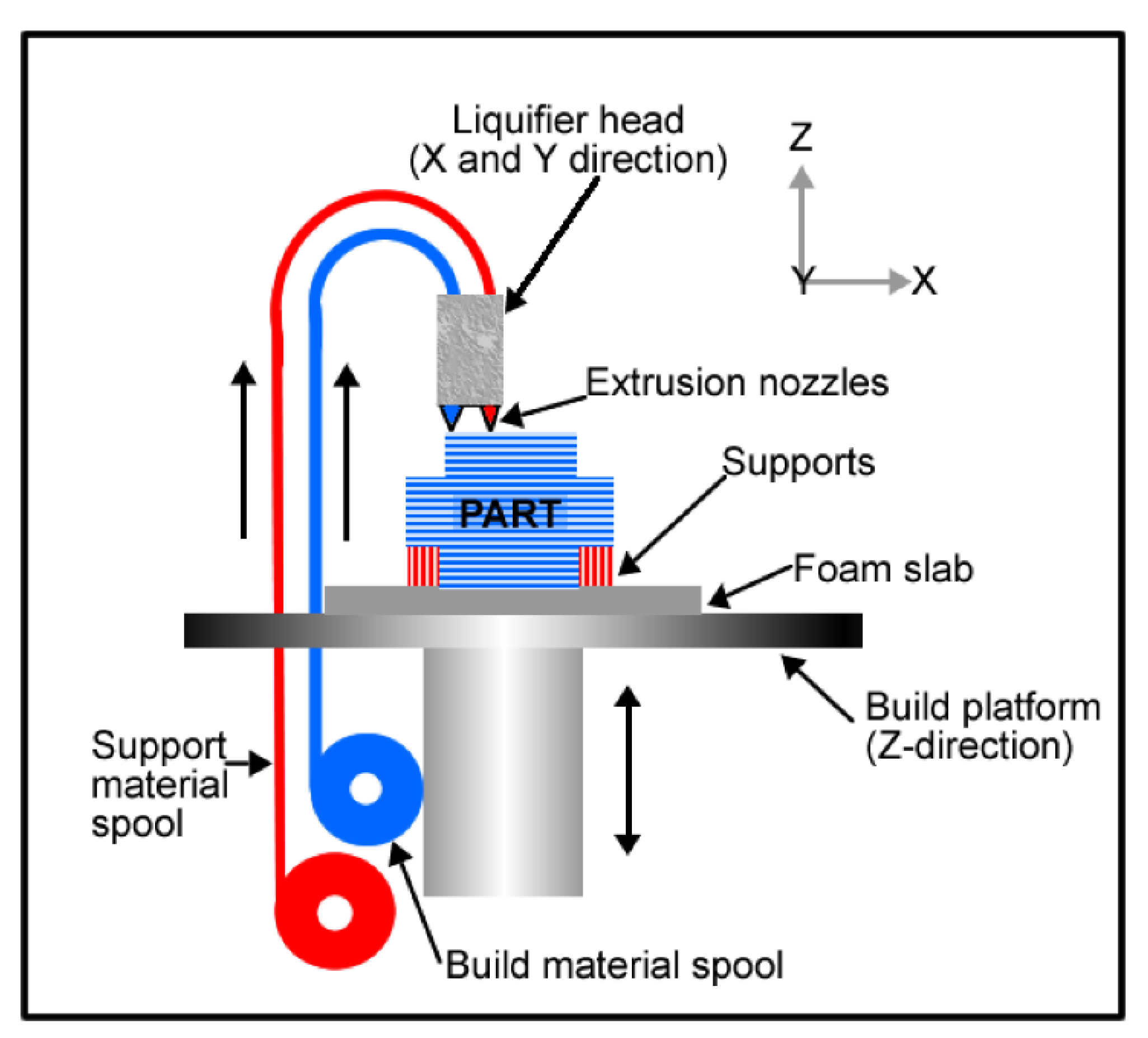
2.4. Material Extrusion Process

The material (generally polymers) is extruded in a layer form in this process. This process continues until a 3D part is achieved using a CAD file. Figure 4 shows the schematic of this process [22]. It allows for a wide range of implant design options, resulting in a wide range of patient-tailored implant products [22].

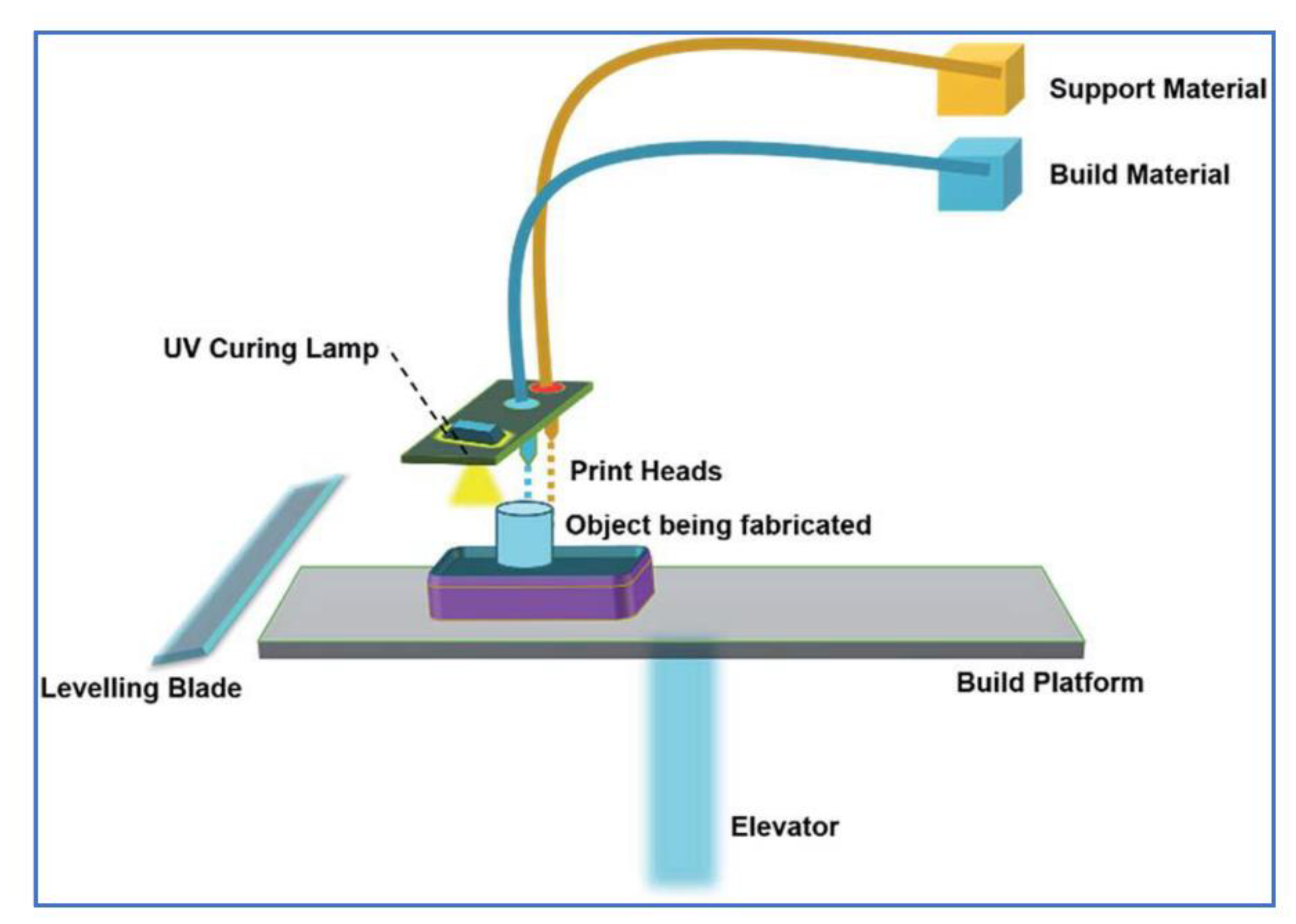
2.5. Material Jetting Process

Figure 5 shows the schematic of the material jetting process [23]. It can be divided into continuous inkjet (CIJ) printing and drop-on-demand (DOD) printing. The timing of droplet production is a critical distinction between CIJ and DOD. CIJ uses an ejection nozzle to break up an ongoing stream of droplets, whereas DOD generates droplets as needed. CIJ and DOD employ ABS, polyamide, PLA, and composites materials [24].

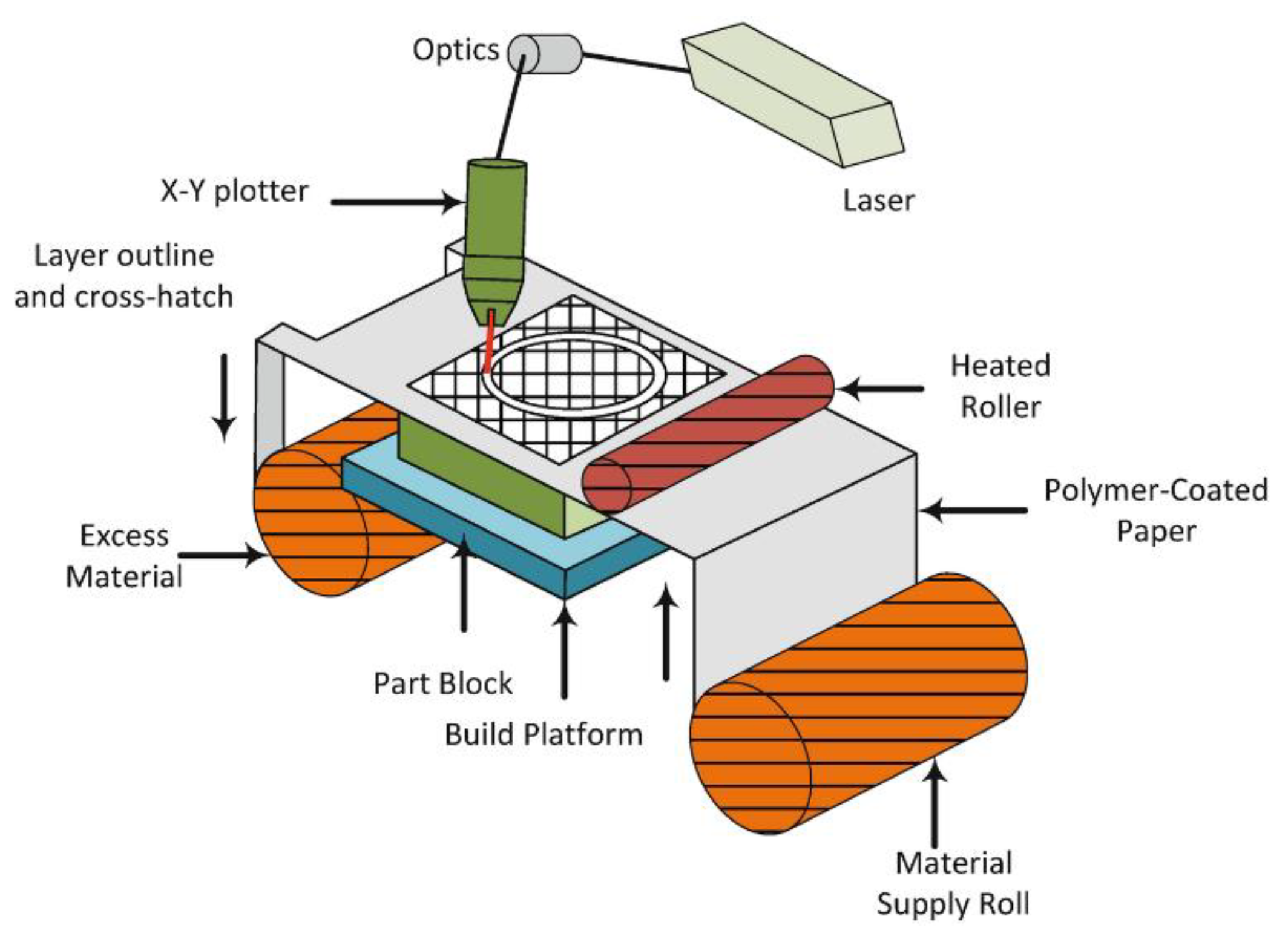
2.6. Sheet Lamination Process

The sheet lamination process is a manufacturing process that uses cutting, sequential laminating and bonding to produce items and prototypes. With the help of ultrasonic welding and a laser cutter, tiny adhesive-coated metallic sheets or layers of plastic can be connected. An example of sheet lamination is illustrated in Figure 6 [25]. As the process uses solid-state bonding and extra adhesives, the material does not need to reach its melting temperature for binding. The sheet lamination process can produce objects from various materials, most commonly ceramic tiles to metals.

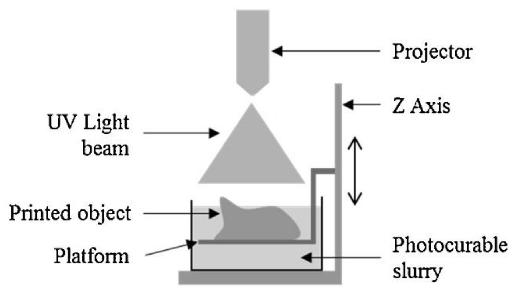
2.7. Vat Polymerization Process

Figure 7 depicts the vat polymerization process schematic [26]. The photopolymerization of liquid monomers is achieved by UV-assisted photopolymerization. An ultraviolet (UV) laser is used to cure a liquid monomer layer. After the first coating curing, the second layer of resin is sprayed at the top of the previously deposited layer. There are many cycles of re-coating and curing to achieve a 3D part [26].

3. Defects in Additively Manufactured Parts

Aluminum, titanium, stainless steel and nickel alloys are the most commonly used feedstocks for AM. High reflectivity and thermal conductivity in aluminum alloys are the primary cause of defects [27]. The AM process’s defects are pores, cracks, anisotropy, residual stresses, thermal stresses, laser spattering, poor surface roughness, and shape distortion [28,29]. The residual stresses are the stresses that persist in a part even in the absence of external loading. In contrast, thermal stresses are usually induced by any change in a material’s temperature [30]. There are various root causes for defects formation in the AM process. Here, we have compiled a few defects and their reasons.

3.1. Porosity Formation

Porosity is a significant flaw in the AM parts [31]. The density of a component indicates its material strength, hence the projected end performance [32]. One may classify the porosities in the AM component into two types: (a) metallurgical pores, which are caused by the absorption of the surrounding gas or by the evaporation of particular alloying elements, and (b) parameter-based holes, which are caused mainly by successive dilation/constriction cycles that lead to local failures [33]. As a result, “macro-porosities” are more dangerous than “micro-porosities.” Indeed, if macro-porosities are not precisely spherical, they can act as a cause of fractures. Micro-porosities may become critical, particularly after heat treatment [34]. Micro-porosities tend to consolidate during such operations, generating macro-porosities that are acicular in shape and hence more prone to cause the previously stated difficulties [29]. Porosity formation can be attributed to a variety of factors, including process parameters, the presence of impurities in the base material, material’s low absorption of laser energy, problems with the solid material’s wettability, the combustion chamber’s atmospheric conditions, or evaporation phenomena of the alloy’s constituent elements [35].

3.2. Cracks Formation

Another defect encountered during the AM is crack formation [36]. The lack of liquid supply to the inter-dendritic spaces causes voids during solidification. It can be attributed to the extensive solidification range. One method to avoid these voids is to modify the composition of the alloy by increasing a particular amount of a specific element, identified by the trial and error method based on the given alloy [37]. For instance, adding silicon to the aluminum alloy will increase the eutectic phase and reduce the melting temperature and the solidification range, thus decreasing the hot cracking level [38].

3.3. Anisotropy in the AM-ed Parts

In AM, another type of defect is the anisotropy of mechanical characteristics. The degree of anisotropy in the generated component depends on the part’s building orientation [39] and the complicated thermal history that the part has endured during AM [40]. Thijs et al. [41] identified that the part’s anisotropy could be controlled by choosing an optimum laser scanning strategy. Prashanth et al. [42] showed that some parameter combinations might result in anisotropic characteristics within the produced components. Thus, the building orientation and the supports used during AM play an essential role in part’s anisotropy [35].

3.4. Surface Roughness Problems in AM-ed Parts

Most of the parts produced via the AM process present poor surface roughness. On the other hand, the best way to take advantage of the AM process is to build a part without post-processing. This goal has not yet been attained. This problem can be resolved by defining a deterministic relationship between operating conditions and surface quality. However, by improving the surface characteristics, one can cause other flaws in the produced components, and thus, the available solutions are limited. The laser parameters utilized directly affect the stability of the melt pool and, as a result, the homogeneity of the final bead [43,44]. AM also exhibits the balling phenomena, which results in a coarse melt pool. This phenomenon is affected by the surface quality and is dependent on process parameters. Olakanmi [45] demonstrated how laser power and scanning rate affect surface morphology. According to Louvis et al. [44], low laser scan speeds increase the surface roughness. Furthermore, surface roughness can be addressed by using a contour scan to reduce surface inhomogeneity and skywriting to allow more uniform energy density scanning [46].
There are still numerous drawbacks of AM processes that affect their application in demanding branches of industry. However, various techniques are available to improve the structural and mechanical properties of the AM parts. These techniques will be discussed in detail in Section 4 of this paper.

4. Various Post-Processing Techniques for AM-ed Parts

The following sections discuss the application of post-processing techniques in the AM process.

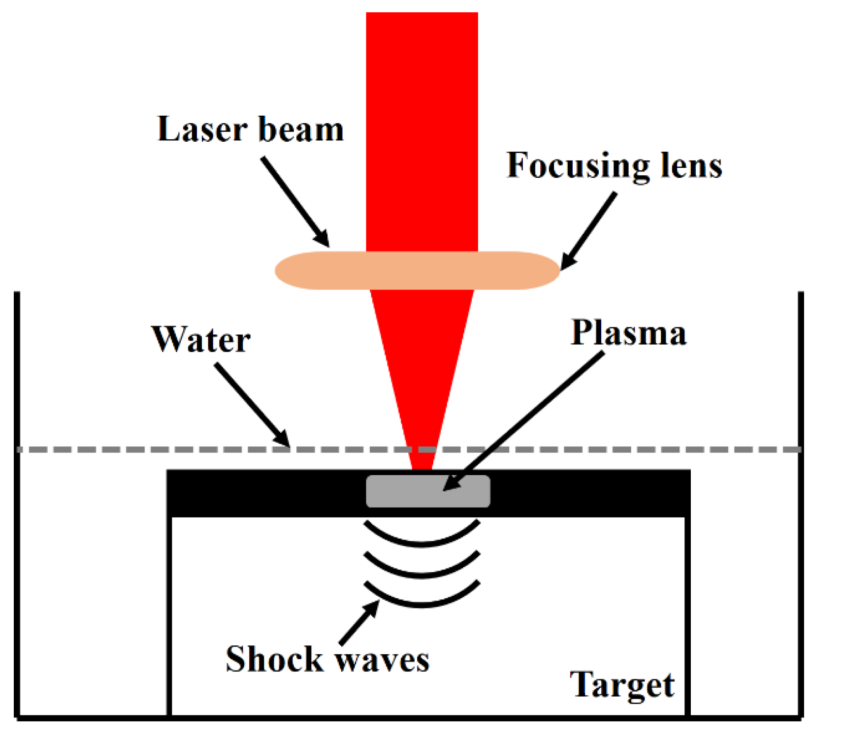
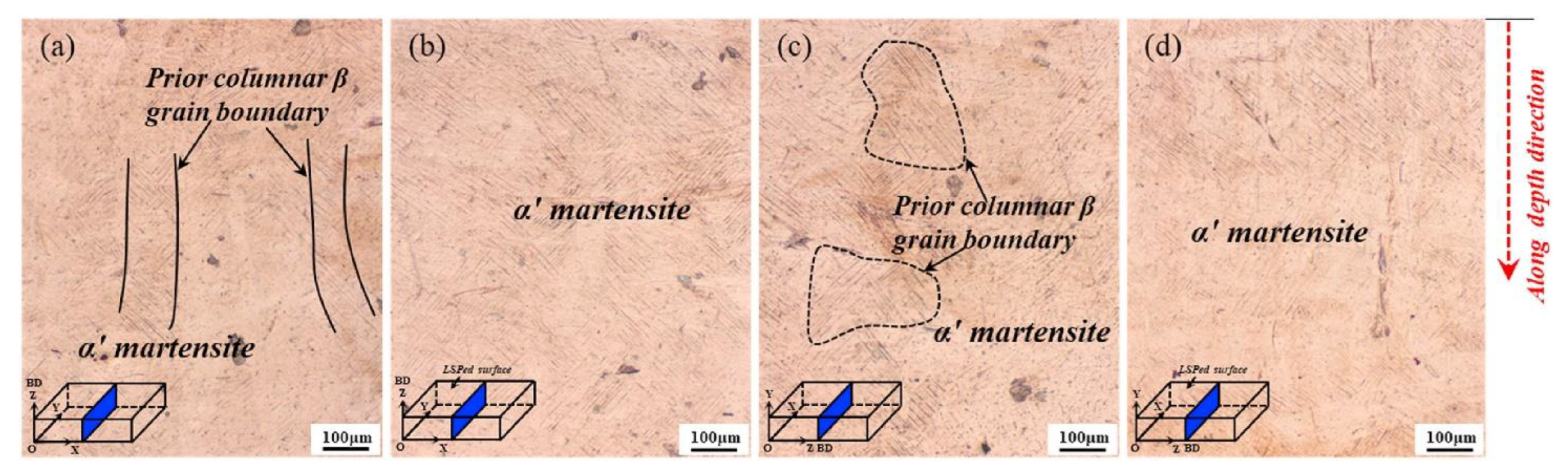
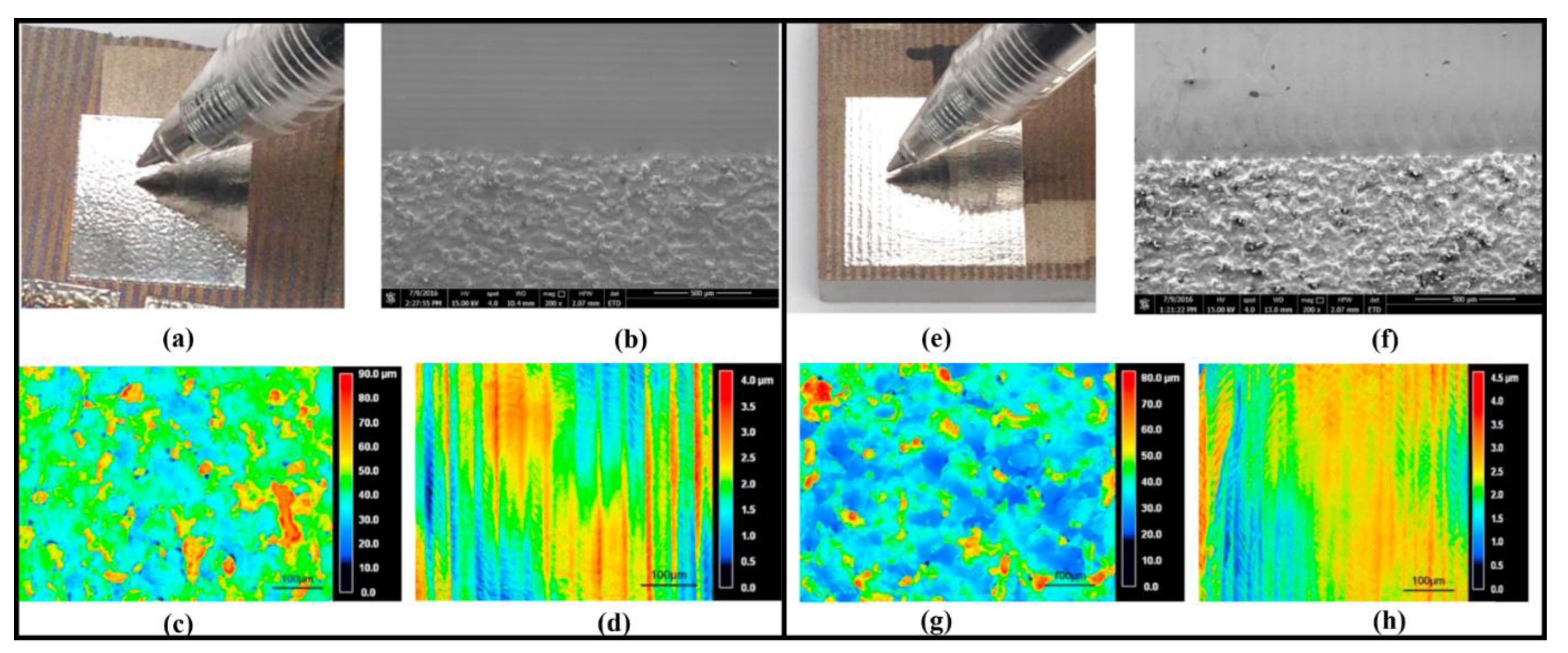
4.1. Laser Shock Peening (LSP)

LSP is a lateral expansion procedure that involves the material’s plastic compression perpendicular to the surface. The ability to withstand transverse strain leads to the accumulation of local compressive stresses when laser peening is done on thick or restricted objects [47,48]. The strain rate is much higher in the thinner parts than the thicker ones since LSP generates compressive residual stresses in the material [49]. Figure 8 depicts a schematic of an LSP process on a metal plate. The heated zone, using a focused laser beam on the metallic surface for 30 ns, reaches 10,000 °C, resulting in plasma formation. The generated plasma absorbs laser energy until the laser-material interaction time is attained. Shock waves transmit the pressure generated by the plasma to the material. Direct ablation means generation of plasma plume by evaporation of laser irradiated material that expands with supersonic velocity, creating a shockwave in the opposite direction with respect to the plume expansion that exerts pressures equivalent to a few tenths of GPa [50]. To achieve a high amplitude of shock pressure, the LSP process typically employs a “confined mode”. The metallic surface is coated with an opaque material such as black paint or aluminum foil, insulated against direct laser radiation by a transparent material. According to recent research, when adopting the confined mode, plasma pressures up to 10 GPa on the metallic surface. With a high magnitude of compressive residual stress, a more powerful pressure pulse may improve the outcome of LSP to a deeper depth [51].
LSP is usually applied to extend the fatigue life of any component, and it has recently been used to improve the fatigue life of aircraft components [48]. LSP has also been used to enhance the properties of maraging steels [52,53,54]. Furthermore, it has also been used to bend and stretch aircraft fenders to produce more feasible aerodynamic models [48]. Short but intense laser pulses form a plasma within the constrained geometry and cause pressure pulses, thus inducing local plastic deformations. The generated pressure can be increased and assist in efficient operation [48].
Fairand et al. [55] used a large pulsed laser for producing the stress waves to alter the microstructural and mechanical characteristics of 7075 aluminum (Al). The 0.2% offset yield strengths of 7075-Al and unaged 7075-Al were increased by as much as 30% over unshocked values. Here, material ageing indicates changes in its original state, but it does not always imply deterioration or degradation [56]. Ageing can also result in the new substances formation and the stability alteration of existing ones. This impact is desirable in some circumstances. Low pressure-induced residual stresses and their effects on fatigue life and stress corrosion behavior of several metallic alloys have been studied, including titanium [57], Al [58], steel [59], and nickel-base [60] alloys. Various scientists also determined the process factors that influence 6061T6-Al mechanical characteristics, fatigue life, and residual stresses [61,62,63].
Salimianrizi et al. [64] analyzed the effects of LSP on Al 6061-T6. An Nd:YAG laser beam with 1200 mJ of energy per pulse and an 8 ns pulse duration was used to apply the confined LSP. The findings revealed that compressive residual stress could be efficiently produced on the surface of the treated material. Work hardening and grain refining were also effective for elevating the material’s hardened depth to a maximum of 1875 µm. Furthermore, surface roughness measurements revealed that the LSP could degrade surface quality depending on the operating conditions. It can be interpreted as a result of local plastic deformation caused by plasma-induced shock waves, the primary source of the surface’s compressive residual stress. The upper surface of the sample is a clean straight line, as illustrated in Figure 9a, exhibiting the considerable effect of polishing before LSP. A sample image of a single LSP with 50% overlap is shown in Figure 9b. Despite using sacrificial confinement layers, the micrograph shows an uneven surface, which could be related to plastic deformations during LSP.
Figure 10a shows the schematic of successive laser shots with laser scan overlap. Here, only one laser beam scan was performed along the Z-axis, while a laser scan overlap (%) was applied to perform multiple scans along X-and Y-Axes. Roughness tests were performed on the specimens treated with single-laser-shot along the X- and Y-directions, as illustrated in Figure 10b [64]. Compared to the unprocessed surface, the LSP significantly enhances the surface roughness. This increase can be explained by local plastic deformation caused by plasma-induced shock waves, the primary source of compressive residual stress on the surface. The roughness values are also different in the X- and Y-directions due to the scanning pattern and overlaps. It can be seen that increasing the overlap from 20 to 50% improves surface roughness. The 70% overlap, on the other hand, reveals a significant increase in the roughness.
LSP for AM-ed Inconel 718 was reported by Jinoop et al. [65], and the parametric analysis was carried out by adjusting peak laser power and the number of shots. For the hardness and depth of the sample, the laser power was 170 mW, and the number of shots was 7, respectively. It was found that LSP altered the produced structure’s surface morphology and mechanical properties. The surface investigation revealed a maximum profile depth of 10 µm and a hardness of 360 HV measured via an optical profilometer and Vickers micro-hardness, respectively. After LSP, the compressive residual stress on the AM sample surface was 214.9–307.9 MPa. The wear rate of LSP-treated AM samples improved by 1.70 times compared to as-built samples. The wear behavior of untreated and treated samples is shown in Figure 11 [65]. The SEM images clearly show particle detachment from the sample’s surface due to delamination. The plate-like debris particles, in Figure 11a,b represent indications of delamination that are caused by adhesion and metal-to-metal contact [18]. It was also discovered that LSP reduces the number of debris particles rising from the surface, linked to the elevated residual compressive stress and hardness. It can be ascribed to the reduced pores quantity in the LSP treated samples compared to untreated samples. As explained above, a specimen under LSP treatment experiences localized melting and re-solidification that reduces the pores percentage [50]. Figure 11e shows the variation in wear rate as a function of different LSP process parameters. It was discovered that when the laser power and number of shots rise, the wear rate reduces significantly. The number of shots seems to be more prominent than laser power variation. The specific wear rate varies according to the micro-hardness data, with the lowest specific wear rate occurring at 200 mW laser power and 7 shots.
Compared to other Al-alloys, AlSi10Mg is an age-hardened cast aluminum alloy with improved mechanical properties and exceptional cast-and-weldability [66]. LSP’s considerable effects on stress corrosion and fatigue characteristics have been widely studied and understood. Damon et al. [67] used micro-tomography analysis to compare the shape and porosity distribution of AM AlSi10Mg parts before and after LSP. The LSP process resulted in a significant reduction of porosity (15–30%). Using density measurement, roughness characterization, and hardness measurements, Sagbas [68] studied the effects of LSP, abrasive blasting, and laser polishing on textural parameters of direct metal laser sintered AlSi10Mg components.
In comparison to shot blasting, LSP can improve the surface’s hardness and strength while reducing the surface roughness. The kurtosis of the LSP surface was <3, indicating that the shot peening surface’s height distribution is flattened. As the skewness of the same surface is negative, the surface deviation height is greater than the average, indicating that the kurtosis and skewness profile parameters play an essential role in characterizing surface texture properties. They are indicators of quality in ISO-4287 [67]. The surface that has been shot-peened has the finest wear resistance.
Different laser intensities were used by Maamoun et al. [69] to improve the surface properties of as-processed AlSi10Mg components. Under varying LSP intensities and sample surface textures, the impact of LSP on the microstructure of as-built AlSi10Mg samples was examined. As shown in Figure 5, SEM studies revealed a considerable alteration in the as-built microstructure. In the as-built + LSP sample, the distorted layers near the surface due to plastic deformation are depicted in Figure 12a. In Figure 12b,c, the fibrous silicon (Si) network surrounding the Al-matrix grains in the as-built microstructure was decomposed, followed by dynamic precipitation of spherical Si particles. Following LSP, the nanoscale Si particles were precipitated in a size range of 100–500 nm and homogeneously disseminated in the affected area, as demonstrated in Figure 12c. The microstructure of the machined surface utilizing high-intensity LSP (machined surface + high-LSP) is shown in Figure 12d–f. The area near the surface was influenced by the circular stress waves that started at the shot position along the surface and extended to a depth of 10 µm, as shown in Figure 12d. As compiled in Figure 12e, microcracks and the layers beneath the sample surface were also discovered. The microcracks vanished at a depth >10 µm from the sample surface. It is worth noting that the microcracks did not emerge inside the microstructure of the as-built + LSP sample, implying that the sample’s original surface texture influences the beginning of these cracks after LSP. The absence of the stress waves pattern and the use of a high surface covering factor value increased the microstructure homogeneity of the nano-recrystallized grains to depths of more than 10 µm (200%). The area affected inside the machined surface + high-LSP sample was extended to a depth of 130–150 µm, as shown in SEM pictures (Figure 12f). The microstructure of the machined surface + LSP sample is depicted in Figure 12g; no stress wave patterns were seen due to the use of low-intensity LSP, which reduced the plastic deformation strength. The machined surface + LSP sample depth was roughly 110–120 µm, which was smaller than the machined surface + high-LSP sample. Due to the low-intensity LSP, Figure 12h,i show incomplete dynamic precipitation of Si particles. The Si particles precipitated in the machined surface + LSP sample were more significant than those in the machined surface + LSP sample. These results were in relation to Cho et al.’s findings [70].
LSP was employed by Chen et al. [71] to modify the surface properties of nano-TiC particle-reinforced Inconel 625 nanocomposites. The effect of LSP was examined on surface morphology, residual stress, microhardness, microstructure and high-temperature oxidation behavior of AM parts. It was discovered that the strong plastic deformation caused by LSP could eliminate pores in the as-built sample. With a 460 µm hardened layer, the maximum hardness was 462 HV, and the surface stress state was switched from tensile to compressive. The (111) and (200) diffraction FWHM values expanded, attributed to grain refinement and a rise in lattice strain of the samples. It was also discovered that the LSP induced the transformation of a substantial number of columnar dendritic structures in the as-built sample into cellular dendritic structures. The walls with a high dislocation density were generated in the LSP sample. Jiang et al. [72] performed systematic analyses on 3D printed Ti6Al4V alloy specimens. They determined that LSP can refine microstructure, suppress residual stresses, and delay crack propagation. Still, it cannot eliminate the inherent defects in an AM part, such as un-melted powders, lack of fusion and clusters of α-phase, which significantly reduces the fatigue performance. Chi et al. [73] applied a combination of heat treatment and LSP to change the microstructure and mechanical characteristics of Ti17 titanium alloy. The results showed that severe plastic deformation was induced in the surface layer, which, in turn, led to a high-level surface compressive residual stress (~763 MPa). Meanwhile, high-density dislocations and mechanical twins were analyzed in coarse α-phases after treatment, which gradually evolved into refined α-phases. The samples’ elongation was significantly enhanced by 15% while ensuring original ultimate tensile strength (1153 MPa).
Lu et al. [74] performed the LSP on Ti6Al4V samples to alter the mechanical properties by changing microstructures. Mechanical properties of metallic components are influenced by microstructure parameters such as grain size, dislocation density and distribution, and density. Figure 13 depicts typical cross-sectional views of all specimens. In all cross-sections, there are few pores but no apparent cracks or incomplete dissolution. As demonstrated in Figure 13a, some long columnar grains may be detected inside the horizontal AM specimen, and these long columnar grains are parallel to the building direction. The temperature of the melt pool generated by the laser steadily lowers from the bottom plane to the top surface throughout AM processing, while the solidification speed gradually increases. The melt pool solidifies from the base plane, and such solidification circumstances cause columnar grains formation. The latter layer’s laser beam will cause the previous columnar grains to re-melt, acting as a nucleus for the epitaxial development of the heavily textured grains. A substantial amount of fine acicular martensite can be seen inside the preceding grains, which is linked with the improved micro-hardness of AM specimens. Figure 13b depicts the cross-sectional microstructure of the horizontal AM-LSP specimen. There are no visible long columnar previous grains that can be refined by LSP and transformed into equiaxed grains. As presented in Figure 13c, the vertical AM specimen contains many acicular martensites of varying lengths. Typical previous grains in the shape of irregular polygons can also be seen in the vertical AM specimen, which differs from the horizontal one. Ti6Al4V is α + β dual-phase alloy, but no phase was seen in the AM specimens. It can be explained by the ultra-fast cooling rate (103–106 K/s) that immediately converts phases into supersaturated solid solutions. However, these phases have different crystal structures than the parent phase, namely α′ martensite structures. A significant number of acicular α′ martensite is parallel to 45°. At the cross-section of the vertical AM specimen, several overlapping α′ martensite emerges in various areas. The vertical AM-LSP specimen’s typical cross-sectional microstructure is shown in Figure 13d. Similar microstructures, such as acicular α′ martensite, may be found in cross-sections of both AM-LSP specimens (Figure 10b,d). There is modest acicular martensite in AM-LSP specimens compared to both AM specimens. Still, the density of acicular martensite in the surface layer significantly increases due to LSP.
Sidhu et al. [75] investigated the effects of LSP on AM Inconel 718 specimens. With the increase in laser energy density, it was found that both compressive residual stress and hardness increased after LSP treatment. After high-energy LSP treatment, the as-built samples presented the compressive residual stress of 875 MPa, and the hardness increased from 468 to 853 HV.

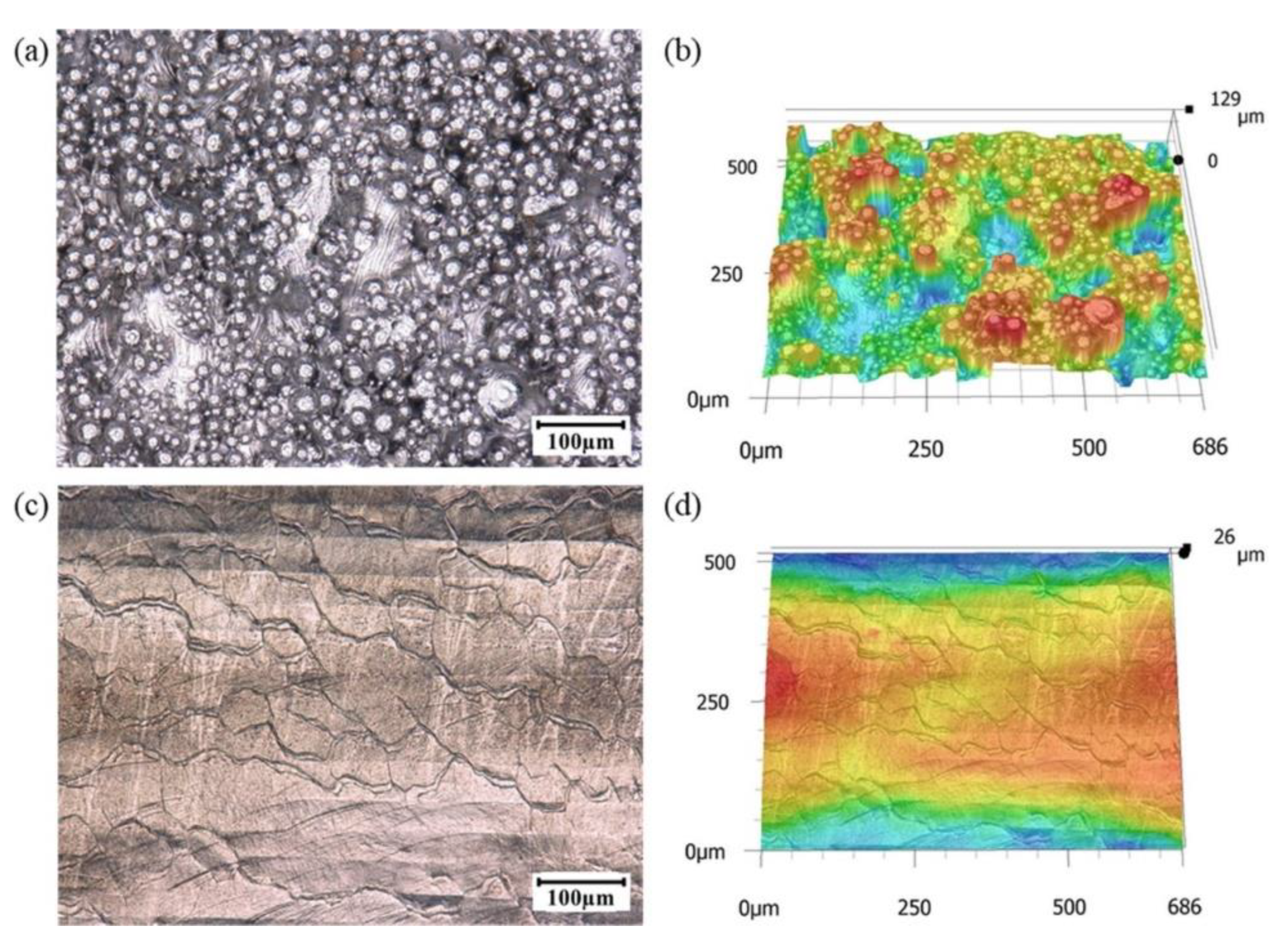
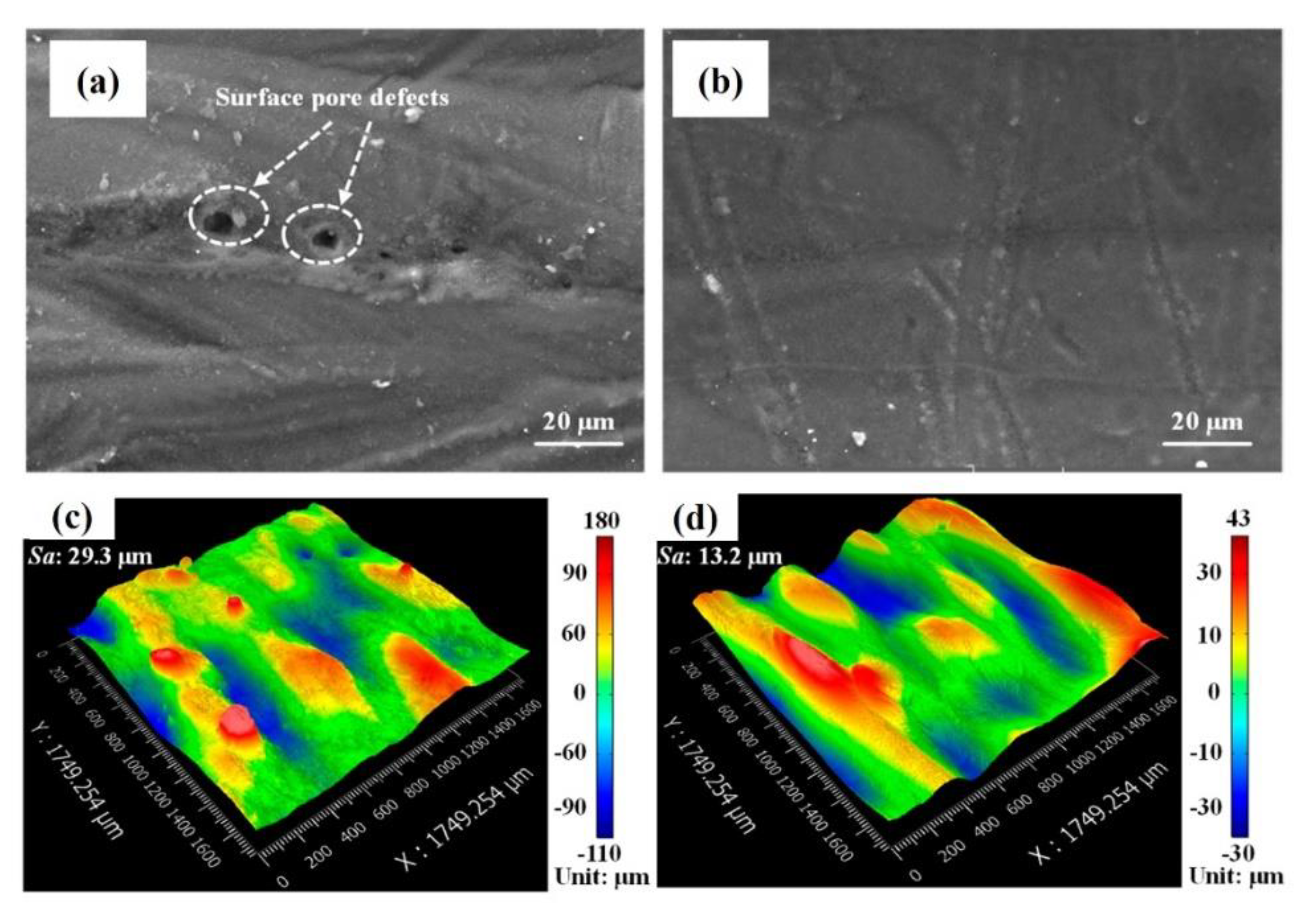
4.2. Laser Polishing (LP)

LP is a technique to improve the surface roughness of AM-ed parts. When the laser energy irradiates the material surface during LP, morphological apexes quickly attain the melting temperature. Due to gravity and surface tension, the liquified material reorganizes to the same level after the melt pool is generated. The heat-affected zone (HAZ) temperature lowers rapidly once the laser beam stops scanning the surface, resulting in melt-pool solidification and reduction in surface roughness [76,77,78]. LP is a technique that re-melts to modify the surface morphology without affecting the bulk characteristics [79].
Mai and Lim [80] applied laser irradiation to polish AISI 304 stainless steel surface. The melting depth was in the sub-microscopic region, while the polishing rate was in the range of 5–15 cm2/min. Due to LP, surface roughness decreased from 195 to 75 nm. LP induced an increase in specular surface reflectance of 14% and a decrease in diffusive reflectance of 70%. The heterogeneous microhardness distribution was converted to a homogeneous distribution. LP could improve pitting corrosion resistance because of the microstructural changes generated by laser rapid melting and re-solidification. The melting action is beneficial in sealing the micro-pores and -cracks, hence reducing surface scratches. Guo et al. [81] used an experimental orthogonal design (OD) to determine the laser operational parameters to reduce the experimental duration in attaining a superior surface finishing of AISI 01 tool steel by pulsed Nd:YAG laser. The results demonstrated that the orthogonal design made it possible to swiftly and effectively obtain the optimum parameters. Based on OD analysis and experimental data, the optimum LP parameters are pulse energy = 1 J, feed rate = 300–400 mm/min, pulse length = 3 ms and pulse frequency = 20–25 Hz. These conditions reduced the surface roughness from 0.40 to 0.12 µm by applying these conditions. Lamikiz et al. [82] employed LP for selective laser sintered metallic components. The results indicated clear roughness reductions for AISI 420 stainless steel + bronze. Surface roughness was reduced to 80% (7.5 to 1.2 µm). The metallurgical studies indicated that the HAZ had no cracks or porosity. It can be deduced that laser-affected areas had a more uniform composition than untreated parts. On the other hand, the resultant surfaces were tougher and more homogeneous than the initial components. Ma et al. [79] demonstrated the ability of a fiber laser to polish the rough surface of Ti6Al4V and α + β Ti-alloy alloys produced by AM. Figure 14a,e show macro-scale photos of Ti-alloy surfaces after LP. As exhibited in Figure 14b,f, the rough samples were polished, and laser melting trails were visible on the surface of Ti-alloys. Figure 14c,d,g,h show that after LP, the surface roughness of Ti and α + β Ti-alloys decreased from 90 to 4 µm and 80 to 4.5 µm, respectively.
Lee et al. [83] investigated the AM of an α + β Ti-alloy. A continuous-wave fiber laser was used to treat the surface of the manufactured products. The powder particles were re-melted using LP, and new surface morphology was attained. The results are shown in Figure 15a,b. It can be seen that the as-fabricated samples’ surface yielded an enormously random surface with high peaks-valleys values. The samples after LP are presented in Figure 15c,d. One can observe that LP generated smooth surfaces with minor peak-valleys values. One of the benefits of LP is that the surface conditions are usually improved without utilizing any extra material.
Zhou et al. [84] developed a transient numerical model to identify the surface roughness evolution during the LP process. AlSi10Mg samples were polished using various laser hatch distances and laser beam scanning directions to understand surface characteristics. It was found that after LP, the surface roughness was reduced from 12.5 to 3.7 μm due to the re-melting of the material. The hardness value was improved from 112.3 to 176.9 HV with grain refinement and surface defects elimination. Figure 16a,b show that the LP process eliminated the part’s pores. After LP, the peaks-valleys variation was reduced significantly, as shown in Figure 16c,d.
Zhou et al. [85] investigated Ti-alloys LP experimentally to identify an optimum laser energy density to reduce the surface roughness. A combination of operating conditions, including laser = 150 W, overlapping percentage = 95% and laser scanning speed = 20 mm/s, reduces the average surface roughness from 3.09 to 0.56 µm. Martensitic structures appeared in the material due to repeated heating and fast cooling thermal cycles, resulting in a 25% increment in hardness value, as shown in Figure 17.
Aviles et al. [86] used the LP process to improve the surface roughness of medium carbon AISI 1045 steel, resulting in enhanced fatigue life. It has been demonstrated that LP improved the fatigue life from 105 to 106 cycles by decreasing the surface roughness from 15 to 5 μm. Chen et al. [87] studied the surface morphology and microstructure of AISI 316 L stainless steel parts before and after the LP process. They found that the average surface roughness decreased from 4.84 to 0.65 μm. After LP, the average grain dimension was also reduced, while the angle of grain boundaries increased from 2° to 5°. A maximum hardness equal to 262 HV was achieved. Rosa et al. [88] investigated the effect of LP on AISI 316L stainless steel surface roughness. They found that the surface roughness was reduced to up to 96% after 5 laser passes. After LP, the surface did not collapse, while the surface topography became smooth, as shown in Figure 18. It can be seen that the final surface still contained several cracks and defects. These defects significantly reduce the fatigue strength. Furthermore, LP yielded a “form” distortion due to the heat transfer from the laser to the top surface.
LP does not influence the microstructure phase type significantly. Obeidi et al. [89] applied LP on AM AISI 316L stainless steel samples. A CO2 laser beam operating in continuous wave mode was used for polishing. The operating conditions, including laser power, the sample’s rotating speed, the number of scanning passes, the laser beam’s focal position, and the overlap (%) of the laser scans between adjacent passes, were considered. The samples’ roughness was decreased from 10.4 to 2.7 µm, while no significant change in microstructure phase-type was analyzed. Tian et al. [90] applied LP on electron beam melted-Ti6Al4V components to improve surface quality. It was found that the surface roughness was reduced by 75% (0.51 μm), which is analogous to a computerized numerical control machined surface. However, the texture of the re-melted layer changed, resulting in a modest increase in sub-surface hardness (15%). The technique generated a high amount of near-surface tensile residual stresses. LP increased the tensile residual stresses in the component’s surface, up to 580 MPa. Chen et al. [91] studied the influence of LP on surface modification and corrosion behavior of AM AISI 316L. Laser scanning speed and number of passes were varied to evaluate their effect on the surface quality and corrosion resistance. The results indicated that LP reduced the surface roughness from 4.75 to 0.49 μm while incorporating partially melted powders originally on the as-printed surface layer. X-ray diffraction (XRD) results indicated no considerable phase change after LP. The sub-surface microhardness increased from 1.82 to 2.89 GPa.
Although the open circuit potential (OCP) cannot measure corrosion resistance, it can reflect the corrosion tendency of the sample in the electrolyte. Metals with a lower OCP are more sensitive to electron loss and oxidation processes. The OCP vs. time curves for the as-printed and LP-ed samples in a 0.4 mol/L HCl solution are shown in Figure 19. The anode changes of the OCP indicate the production of the passivation film. In contrast, the cathode shifts of the OCP indicate the dissolution of the film or the absence of film formation. As shown in Figure 19, all curves include anode shifts at the start of the corrosion test due to the formation of the passivation coating. However, the OCP varies around a fixed value due to the passivation film’s stability as time passes. After 1200 s of immersion in 0.4 mol/L HCl solution, the final stable OCP for the as-printed sample is around −0.483 V. When only 1 laser scanning pass was used, and the OCP stabilized at −0.469 V and −0.471 V. The OCP stabilized around −0.461 V and −0.463 V for 3 laser scanning passes. The LP samples exhibited anode shifts of OCP compared to the as-printed sample, which show that LP can minimize the sample’s corrosion tendency. Furthermore, the time required for the LP sample to establish a stable OCP is reduced when compared to the as-printed sample, indicating that the LP samples produced the passivation layer faster than the as-printed sample.
Lee et al. [83] applied the LP to improve the fatigue performance of AM Ti6Al4V parts. The strain-life fatigue plot is depicted in Figure 20. A different symbol represents each surface and stress relief condition: (a) green triangles for specimens with as-built surface condition (AB), (b) blue diamonds for specimens with LP, (c) red circles for specimens with laser polished surface condition and secondary stress relief (LPSR), and (d) black squares for specimens with machined/polished surface condition as the baseline (M/P). As indicated in Figure 20, the fatigue strength of LP specimens was improved at lower strain levels (i.e., intermediate cycle fatigue (ICF) and high cycle fatigue (HCF)) compared to AB specimens. In the HCF regime, the fatigue lifetimes of LP specimens were at least one order of magnitude higher than those of AB specimens.
Nonetheless, LP specimens displayed lower fatigue strengths at greater strain levels than AB specimens (i.e., low cycle fatigue (LCF)) due to the residual stresses generated on the LP specimens’ surface due to the LP process. Although LP caused unavoidable residual stresses, the influence of surface roughness on fatigue strength in the HCF regime can be more substantial than the residual stresses. As a result, even when additional stress release was not used, LP specimens had longer fatigue lifetimes than AB specimens in the ICF and HCF regimes. On the other hand, surface roughness has less influence on LCF due to the material’s high plastic deformation. As a result, high plastic strain amplitudes may interact with tensile residual stresses to cause even more negative effects. In the LCF regime, the contribution of residual stress may be more significant than the influence of surface roughness. LPSR specimens outperformed both AB and LP specimens in terms of fatigue strength.
Furthermore, under 0.004 mm/mm strain amplitude, one LPSR specimen reached 107 reversals, equivalent to M/P specimens. Because it was the sole variation between the LP and LPSR specimens, the fatigue testing findings implied that residual stresses were satisfactorily reduced by a stress relief method (one hour at 700 °C under an argon atmosphere). However, several tests at 0.004 mm/mm strain amplitude failed before reaching 107 reversals, with one test failing before 105 cycles. At this strain amplitude, the difference between the shortest and longest measured fatigue life is two orders of magnitude; hence, fatigue strength improvement is significant compared to AB and LP specimens. In general, the improvement in fatigue resistance in ICF and HCF regimes follows the AB < LP < LPSR < M/P hierarchy, demonstrating that LP can be a viable technique of improving the fatigue resistance of AM parts by lowering surface roughness.

4.3. Conventional Machining Process (CMP): Milling, Rolling, Chemical Machining and Abrasive Machining

CMP is the traditional manufacturing process employed to enhance the manufactured parts’ dimensional accuracy and surface quality. Owing to the popularity and acceptability at a wide level, they are also employed in AM for the post-processing of manufactured parts. Bai et al. [92] studied the machining of the ASTM A131 steel AM components. They used computerized numerical control (CNC) milling machine. After post-processing, the samples’ surface roughness was smoothened from 22.7 to 0.6 µm, as shown in Figure 21. However, the milling process did not affect the hardness value significantly.
Lopes et al. [93] applied milling process on high strength low alloy steel parts produced by AM process. It was found that the surface roughness upgraded with an increase in the cutting speed and a reduction in tool feeding rate. The maximum surface roughness = 0.641 μm was attained when milling was carried out using cutting speed = 30 m/min and feeding rate = 0.0345 mm/tooth. On the other hand, the least surface roughness = 0.206 μm was obtained when cutting speed = 65 m/min and feeding rate = 0.0115 mm/tooth. Honnige et al. [94] investigated the impact of vertical inter-pass and post-deposition side rolling on the aluminum (2319) walls manufactured by AM process. They found that residual stresses and part defects decreased considerably. Furthermore, the hardness increased significantly with an increment in applied load due to work hardening effects, as shown in Figure 22.
In another study by Scherillo [95], surface finishing of AM-ed AlSi10Mg was carried out by samples’ immersion in a chemical solution. A mixture of HNO3 and HF was used at 85 °C for 75 min. The samples were rinsed in ultrasonic water + acetic acid bath to remove insoluble products. Figure 23 shows a considerable decrease in surface roughness (Sa), ten-point height (Sz), kurtosis (Sku), skewness (Ssk), and symmetrical distribution of peaks and valleys (Sdq) with respect to the etching time. The chemical solution mainly acted upon the peaks, resulting in flat surfaces.
There are various abrasive machining methods. Zhang et al. [96] used magnetic abrasive finishing to polish the AISI 316L stainless steel at multiple angles. The surface finish was improved by up to 76%, and all the defects were eliminated. The impacts of ultrasonic abrasive polishing (UAP) on the surface quality of AM parts were examined by Wang et al. [97]. The Smoothed Particle Hydrodynamics methodology was used to simulate the impact action of abrasive particles. The results showed that UAP could remove partially melted particles, thus reducing the surface roughness from 5.02 to 2.93 µm. Teng et al. [98] investigated the grinding and abrasion processes for AM parts and found that the surface roughness was reduced from 7.0 to 0.15 µm. In the beginning, there are a lot of burrs and pores on the sample’s surface that result in high peaks and valleys variations in a provided sample, thus presenting an increased surface roughness value. The grinding and abrasion processes help in removing the burrs and pores within the provided specimen, which ultimately decreases the surface roughness. Guo et al. [99] performed an experimental and mathematical investigation on abrasive flow machining to enhance the interior surface quality of Inconel 718. The surface quality was improved up to 56% compared to the as-built surface. Han et al. [100] identified the effects of abrasive flow machining on fatigue resistance. It was found that the fatigue resistance was improved up to 26% by using an abrasive flow machining process. Yamaguchi et al. [101] observed a significant reduction in surface roughness (100 to 0.1 µm) and the compressive residual stress formation after performing a sanding, polishing, and ball burnishing on AM AISI 316L stainless steel.
Furthermore, Table 1 compiles the advantages and disadvantages of conventional machining processes.

4.4. Heating Processes (HP)

HP can significantly alleviate the residual stresses, lessen cracks and homogenize the microstructure [110,111,112,113]. There are several HPs; however, the commonly used processes are (a) solution heat treatment (SHT), hot isostatic pressing (HIP), and T6-heat treatment (T6-HT). Various studies have been carried out on the effect of HPs on the microstructure and mechanical characteristics of the AM parts [34,114,115,116,117,118]. The HIP is a typical thermo-mechanical process that combines high temperature and pressure to eliminate the pores and increase the produced parts’ density. The average temperature for this process is between 1000–2000 °C. In a closed container with a working pressure of 200 MPa, high-pressure inert gas is used as the pressure medium. The parts are pressed equally in all directions with high temperature and pressure. As a result, the parts produced have a high density, outstanding homogeneity, and exceptional performance [119]. Short production cycles, low energy usage, maximizing material utilization by increasing material qualities, and allowing for smaller, lighter-weight, high-strength parts are all characteristics of the HIP. The HIP can cure or eradicate intrinsic flaws and porosity in the additive manufactured parts [120,121]. The HIP has been found to significantly improve the fatigue strength of Ti6Al4V produced by electron beam melting [120,121]. In these studies, HIP optimized the mechanical qualities of EBM parts. Due to the reduction in porosity and un-melted material, as well as the coarsening of microstructure, the HIP treatment can yield parts having excellent mechanical qualities [116].
Goel et al. [122] investigated the effects of two different post-processing treatments: (a) HIP and (b) HIP + heat treatment on Inconel 718 alloy manufactured by electron beam melting (EBM). Gas and shrinkage porosity, as well as lack-of-fusion flaws, were identified in the manufactured parts. Figure 24a depicts the total defect measured in both as-built and post-treated specimens. Figure 24b,c show a graphic representation of flaws in the manufactured parts. During printing, the gas was entrapped in the powder, causing the “circular” shaped defects [123]. During solidification, the shrinkage porosity (SP) resulted from inter-dendritic shrinking [124] and consequently appeared along with the build direction, as shown in Figure 24a. It is essential to distinguish SP from liquation cracking, as it is usually linked to the secondary phases [125,126]. SP was identified as an effective mechanism that contributed to the defect formation. Incomplete fusion between the melted layers causes lack-of-fusion (LoF). Both the HIP and HIP + heat treatment post-treatments resulted in a significant defects reduction, as seen in Figure 24a,c. Creep, and diffusion mechanisms are mainly responsible for defects elimination during HIP [127]. The post-treatment products had only 0.01% defects (Figure 24c).
Leon et al. [128] provided a thorough investigation on the stress-corrosion vulnerability of EBM Ti6Al4V for (a) as-build and (b) after HIP. All the related tests were conducted at 3.5 wt.% NaCl solution at room temperature. Figure 25a–f show the macro- and micro-structure of longitudinal and cross-sections of as-built and HIP-EBM samples. Due to the epitaxial growth of the parent grains, both specimens had typical columnar microstructures [32]. As indicated in Figure 25a,b, the macro-structure in as-built conditions was finer and less uniform than the HIP sample macrostructure. Furthermore, the scanning pass of the electron beam was nearly indistinguishable after the HIP heat treatment, despite the columnar macro-structure being primarily retained. Due to the relatively rapid cooling conditions in the EBM process, the microstructure of the as-built sample (Figure 25c) reveals the presence of three main phases: (a) discontinuous grain boundary, (b) fine α-Widmanstätten, and (c) α-primary that nucleates ideally. The microstructure of the HIP sample (Figure 25e) displayed a more extensive and more continuous αg.b-phase, but the primary α-phase and the coarser Widmanstätten α and β structure were retained [14,31]. It is evident from the expanded magnifications of the β-phase in as-built (Figure 25d) and HIP samples (Figure 25f) that the HIP procedure has resulted in accelerated β-phase growth. According to Dai et al. [35], it should improve corrosion resistance and the continuity of the β-phase inside the microstructural region. In the HIP sample, agglomeration of β-phase significantly reduced the overall area of the interfaces between the α- and β-phases.
Karami et al. [129] performed HIP on AM-ed Ti6Al4V lattice structures. During HIP, 920 °C temperature was attained that is just below the β-transus temperature of 996 °C, that transformed the acicular-ά-martensitic structure into β- and α-phases. Initially, during the HIP process, the α-phase is formed along the ά-boundaries. By increasing the α-plates, vanadium withdrew to a nearby regime and β-phase nucleated due to vanadium enrichment. After HIP, the final microstructure consisted of α-platelets embedded in α-/β-grain boundaries [130], as shown in Figure 26.
Yu et al. [131] investigated the effect of the post-processing technique on the microstructure and fracture toughness of Inconel 718 produced by AM process. It was found that as-built samples contained γ-columnar dendrites and a minor quantity of gamma + Laves eutectics within inter-dendritic regimes. After using direct ageing, a heat treatment process, the non-uniform gamma′′/gamma′ accumulated around Laves-phases. After using solution treatment + ageing, the delta-phases accumulated within the Laves-phases, the micro-segregation decreases. After homogenization + solution treatment + ageing, Laves-phase almost vanished. The fracture toughness results indicated that as-built samples showed the minimum fracture toughness owing to the most negligible elasticity modulus and yielding strength. The sample showed the elasticity modulus and yielding strength close to the as-built samples using direct gaining. However, the fracture toughness of solution treatment + aging and homogenization + solution treatment + aging samples increased by 56% and 91% compared to as-built samples. Careri et al. [132] investigated the effects of two post-processing techniques: (a) thermal post-processing and (b) machining, on stresses formation, microstructure evolution, hardness and surface characteristics of AM parts. Due to the material’s higher ductility than as-built parts, the results demonstrated that the strategy of combining heat treatment with machining presented the best machining conditions. In addition, an increment in hardness and a reduction in surface roughness were found.
Brandl et al. [133] executed T6-HT at 525 °C for 6 h, water quenching at room temperature, ageing at 165 °C for 7 h, and machining the AlSi10Mg parts. The results showed that heat treatment increased the fatigue resistance up to 50%, while a combination of heat treatment at (300 °C) and T6-HT enhanced the fatigue resistance by 120% compared to the as-built parts. The primary reason for such an extraordinary result was the transformation of dendritic shapes from Si-spheroids that decreased cracks formation. Maamoun et al. [113] conducted solution heat treatment for 1 h at 530 °C and 5 h at 530 °C, and T6-HT for 5 h at 530 °C. These processes were performed after annealing (200 °C and 300 °C). It was found that solution heat treatment and T6-HT elevated the microstructure homogenization. Furthermore, it was noticed that solution heat treatment reduced the hardness by nearly 50% compared to as-built components. However, T6-HT enhanced the sample hardness by 70% compared to as-built components. Gu et al. [134] investigated the effects of T6-peak-hardening on Al 2219 alloy. They found that this treatment assisted the as-built part in enhancing the yield strength and ultimate strength from 305 to 450 MPa that was much higher than wrought Al 2219 alloy parts. Zhuo et al. [135] examined the influence of two annealing temperatures on AlSi10Mg components: (a) 300 °C for 2 h and (b) 535 °C for 1 h. It was detected that the first set of heat treatments was better in reducing the tensile residual stresses from 111 to 13 MPa. Fousova et al. [136] described that T6-HT could decrease the strength of AlSi10Mg parts at the verge of material stability improvement. It was suggested that such components could not be used for high-strength applications.
Table 2 collects the commonly used post-processing techniques identified based on the literature review.

5. Conclusions and Future Outlook

5.1. Conclusions

This paper has summarized numerous post-processing technologies and their applications in additive manufacturing (AM) processes. In AM, there are various types of defects, including pores, cracks, anisotropy, residual stresses, thermal stresses, laser spattering, and poor surface roughness. Different post-processing techniques, including laser shock peening, laser polishing, conventional machining, and heating processes, have been explored to resolve these issues. These processes have proved their capability to improve the mechanical properties and reduce the residual stresses formation and surface finish of AM products. Based on this study, the following significant conclusions have been deduced:
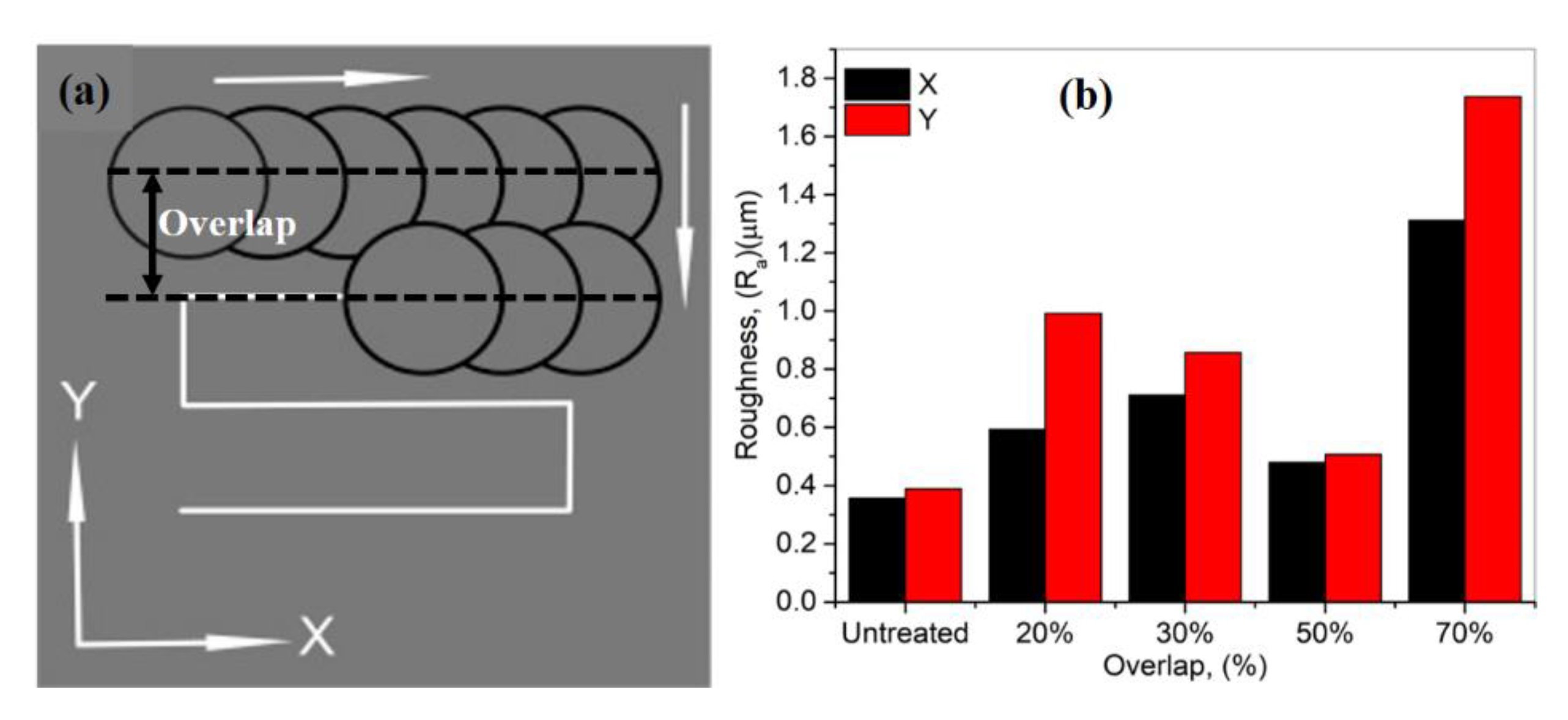
  • The laser shock peening (LSP) has been applied to the bulk and thinner parts. However, this process leads to severe strain generation in the case of more delicate parts. The percentage of overlap between the two laser scans plays an essential role in controlling the final surface roughness value. LSP is inherited with the local grain refinement phenomenon, resulting in elevated hardness value. Another significant factor is the laser beam intensity and the laser wavelength type that control the surface regularities for a given specimen.
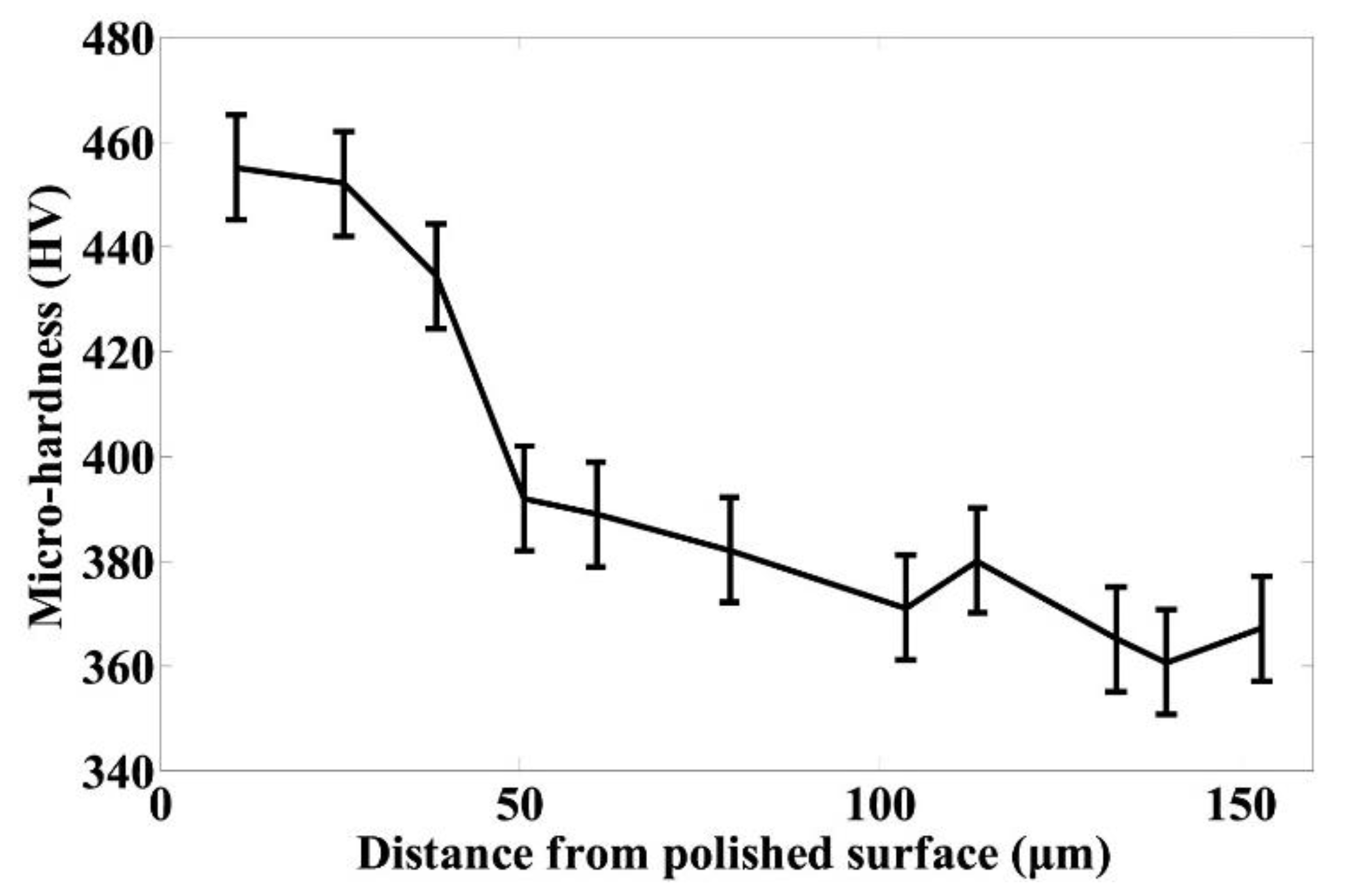
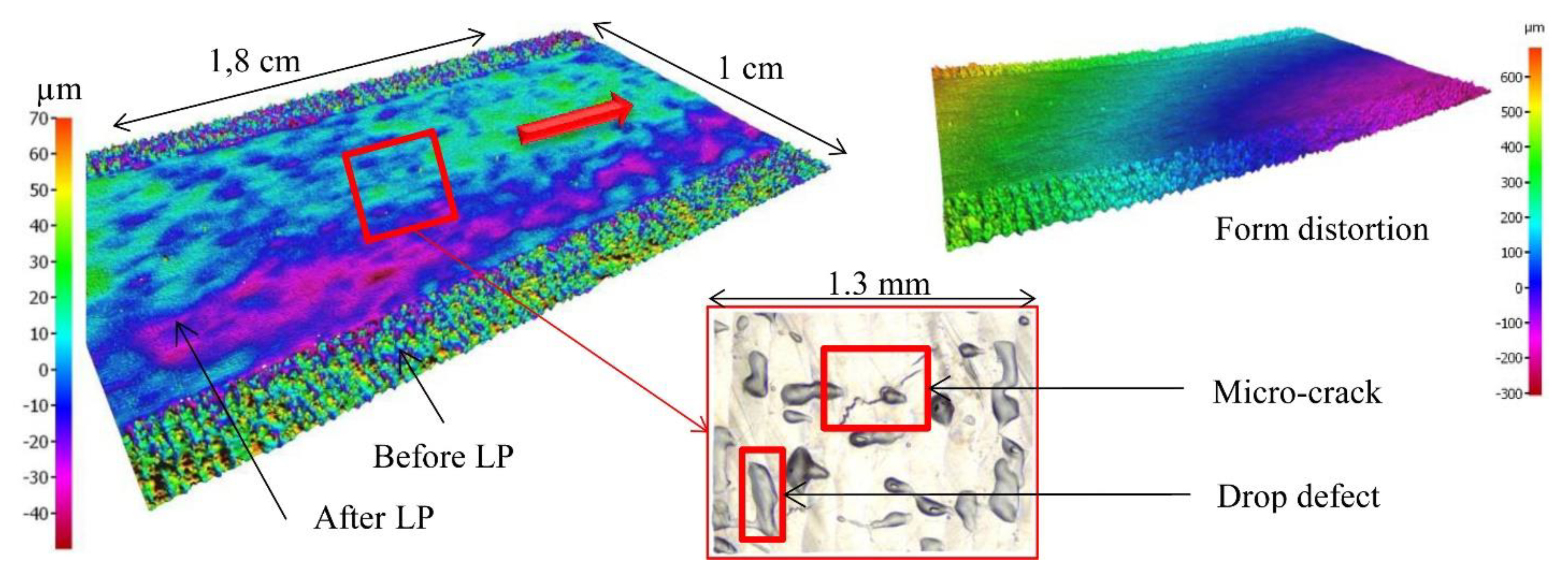
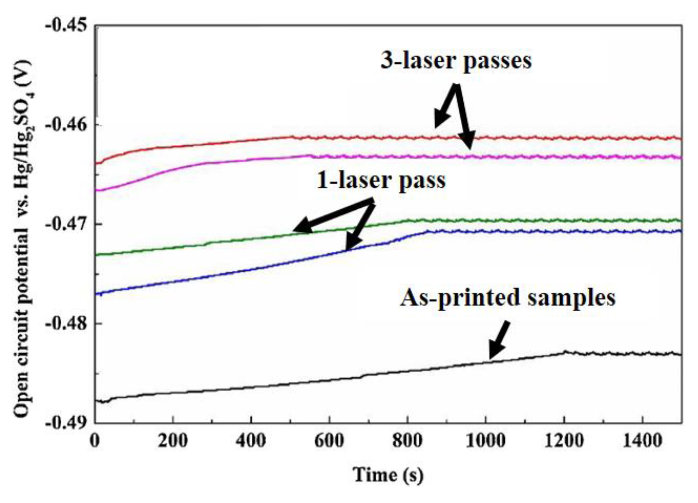
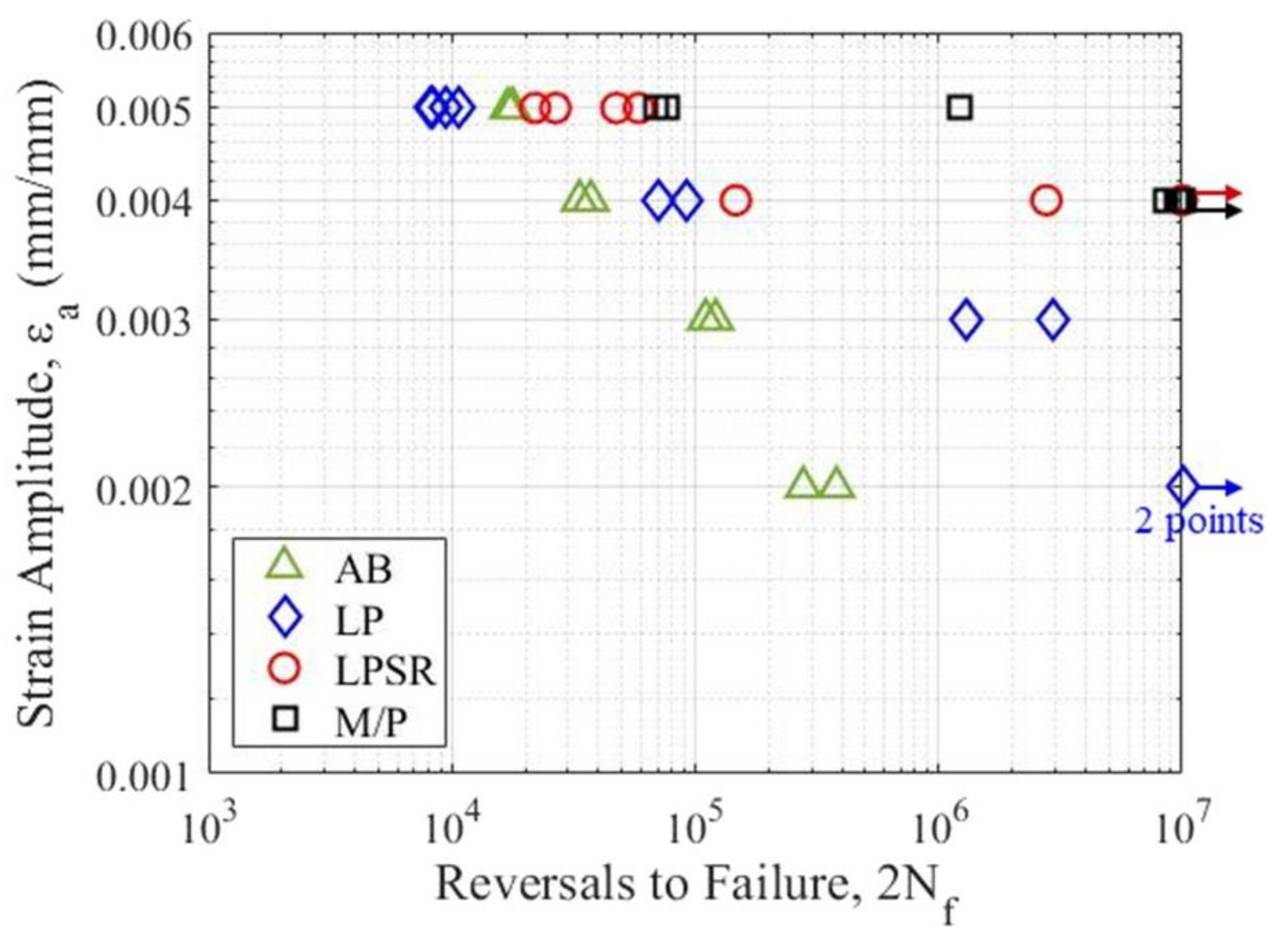
  • Besides LSP, laser polishing (LP) plays an essential role in controlling surface roughness and hardness. LP usually acts on the peaks of a given surface, thus increasing the surface reflectivity. Moreover, the number of laser passes also determines a specimen’s surface quality. It has been identified that laser polishing can decrease the surface roughness up to 95% concerning the as-built specimen. The hardness value is usually maximum at the top of an LP-ed specimen and declines while travelling from the top to the bottom surface.
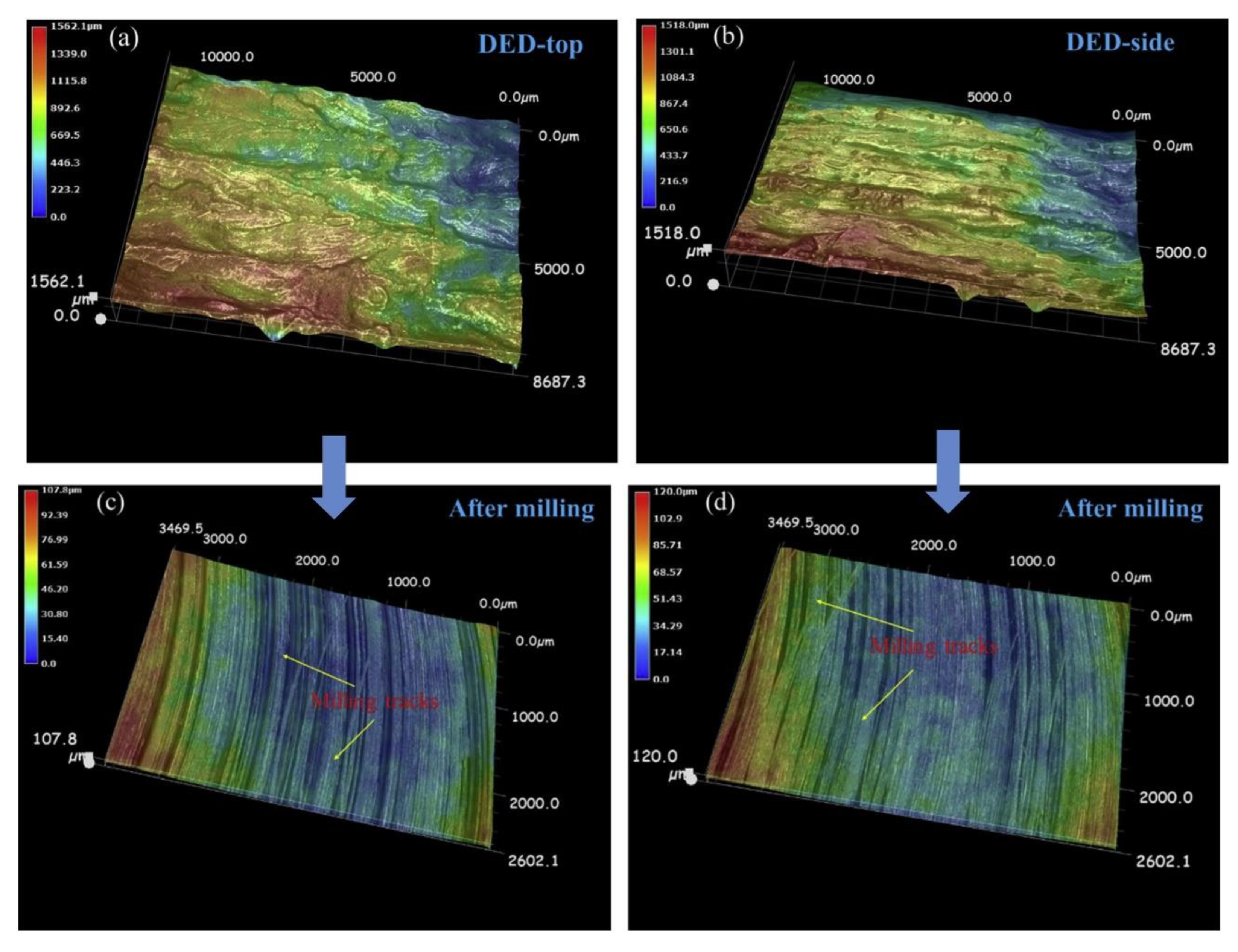
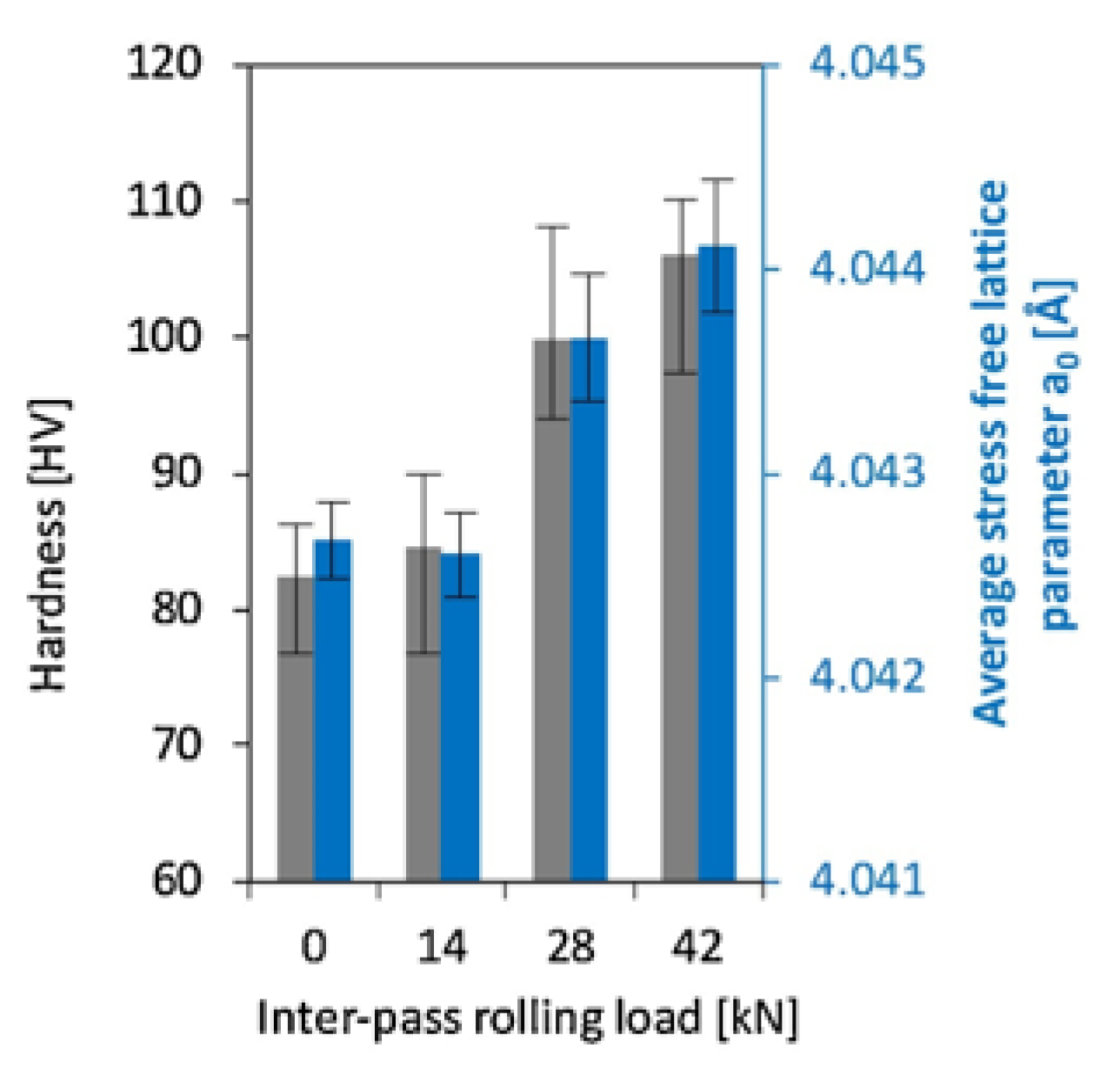
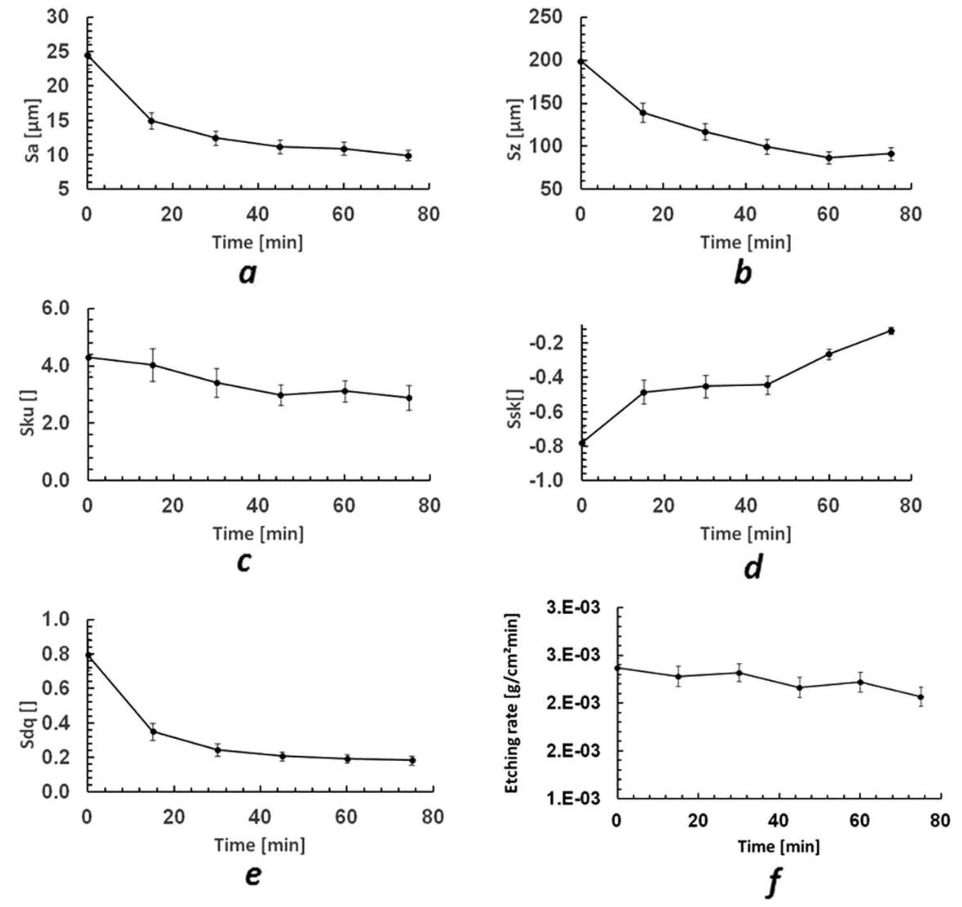
  • Conventional machining processes have proved their viability for the post-processing of AM parts. They are commonly applied to amplify surface characteristics such as surface roughness and skewness. However, their effect on hardness improvement has not been proved yet. These findings are valid in the case of the milling and turning process. The rolling process has also been used as a post-processing technique. It has been identified that the rolling process significantly improves surface roughness and hardness. Besides the mechanical conventional machining processes, there are various chemical-conventional machining processes. The chemical reagent is usually utilized to improve a given surface’s roughness in this category.
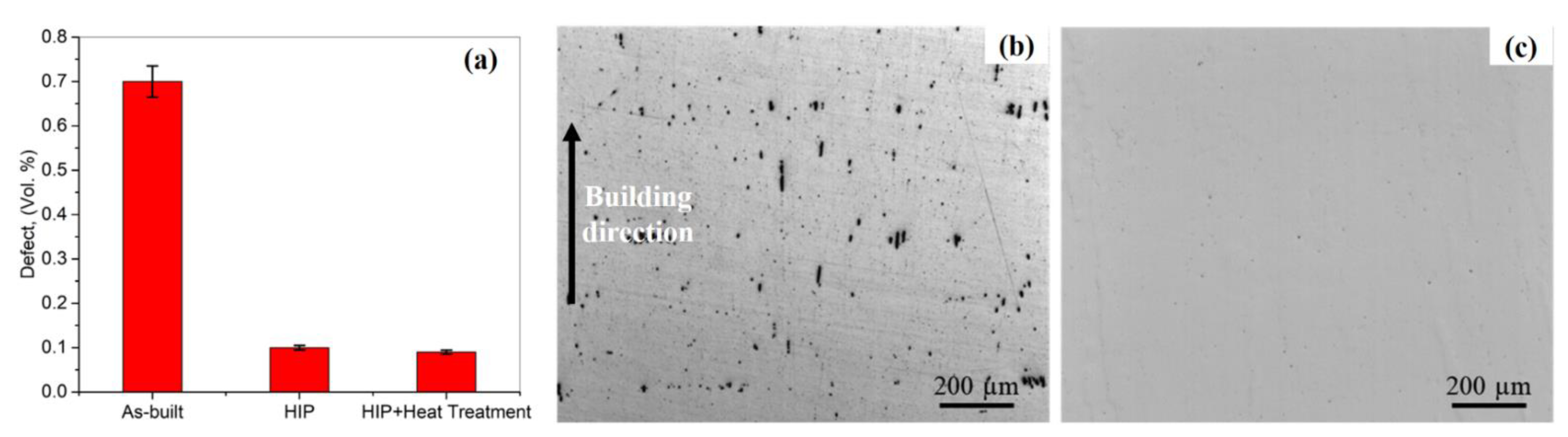
  • Thermal post-processing techniques have commonly been used to eliminate pores, enhance corrosion resistance, and improve mechanical properties. There are various thermal post-processing techniques: (a) solution heat treatment, (b) hot isostatic pressing, and (c) T6-heat treatment. These techniques involve grain refinement and deposited layers’ compactness at elevated temperatures, reducing porosity up to 99.99%.

5.2. Future Outlook

In this section, a few points for the future outlook of post-processing techniques are proposed:
  • Various researchers and scientists have carried out efforts to facilitate AM post-processing commercialization. Each part produced via AM process contains multiple defects. These defects decrease the life expectancy of a produced part and limit its utilization. To prescribe a particular post-processing technique for specific defects, there is a need to establish standardization. These efforts will guarantee a manufactured part’s surface integrity and adequate mechanical characteristics, thus avoiding failure during application.
  • These post-processing techniques have not been explored for ceramic-reinforced metal matrix composites (CMMCs). In CMMCs, the ceramic particulates are mixed with metallic powder materials and can be used in applications where the properties of ceramics and metal materials are required. CMMCs have elevated hardness and high melting-point and require specific tooling compared to metal materials. CMMCs have gained attention worldwide; hence, their post-processing techniques require special attention from scientists and researchers.
  • There is an urgent need for process automation of post-processing techniques in this modern era. These automated solutions can advance production effectiveness. It can be done via machine or deep learning techniques, useful in process automation, process control, and optimal solutions.
  • Process simulations play an essential role in identifying the effect of operating conditions on the final part characteristics. Various simulation techniques for laser shock peening, laser polishing, and conventional machining processes are available. However, the heat treatment simulation techniques have not been well-developed so far. Heat treatment techniques are commonly used in AM process to reduce or eliminate part’s porosity that can increase the operational life of the printed components. Developing the simulation models for heat treatment can assist in understanding the multi-physical processes involved while porosity elimination.
  • In AM, improving the parts’ is a priority; however, reducing the cycle time is also one of the significant challenges. During AM manufacturing, the post-processing techniques consume almost 43% of the total time [137]. During manufacturing, the in situ control of part’s quality can reduce or even eliminate the post-processing technique. It can be done by controlling and optimizing the process at the layer level. Simulation models and in situ monitoring techniques can be developed and applied to understand the AM process at the layer level. It can, in turn, reduce the post-processing technique requirements, thus reducing cycle time and production cost.

Author Contributions

Conceptualization, M.A.M. and A.C.P.; methodology, M.A.M., D.C., A.U.R. and S.M.; formal analysis, M.A.M., D.C., A.U.R., S.M. and A.C.P.; investigation, M.A.M., D.C., A.U.R., S.M. and A.C.P.; resources, A.C.P.; writing—original draft preparation, reviewing and editing, M.A.M., A.C.P. and D.C.; supervision, A.C.P.; project administration and funding acquisition, A.C.P. All authors have read and agreed to the published version of the manuscript.

Funding

This research has received financial support from the European Union’s Horizon 2020 (H2020) research and innovation program under the Marie Skłodowska-Curie, grant agreement No. 764935. This research has been conducted in the framework of POC-G Contract no. 135/2016 and UEFISCDI 45/2021. This work was also supported by grants of the Romanian Ministry of Education and Research, CNCS-UEFISCDI, project number PN-III-P4-ID-PCE-2020-1634, PN-III-P2-2-1-PED-2019-3953, within PNCDI III, and Romanian Ministry of Education and Research, under Romanian National Nucleu Program LAPLAS VI—contract no. 16N/2019.

Institutional Review Board Statement

Not applicable.

Informed Consent Statement

Not applicable.

Data Availability Statement

Not applicable.

Acknowledgments

The authors would like to acknowledge the European Union’s Horizon 2020 (H2020) research and innovation program, Romanian Ministry of Education and Research, and UEFISCDI, Romania.

Conflicts of Interest

The authors declare no conflict of interest.

References

  1. Chen, Y.; Peng, X.; Kong, L.; Dong, G.; Remani, A.; Leach, R. Defect inspection technologies for additive manufacturing. Int. J. Extrem. Manuf. 2021, 3, 022002. [Google Scholar] [CrossRef]
  2. Pandey, P.M.; Reddy, N.V.; Dhande, S.G. Improvement of surface finish by staircase machining in fused deposition modeling. J. Mater. Process. Technol. 2003, 132, 323–331. [Google Scholar] [CrossRef]
  3. Dai, L.; Cheng, T.; Duan, C.; Zhao, W.; Zhang, W.; Zou, X.; Aspler, J.; Ni, Y. 3D printing using plant-derived cellulose and its derivatives: A review. Carbohydr. Polym. 2019, 203, 71–86. [Google Scholar] [CrossRef] [PubMed]
  4. Pyka, G.; Kerckhofs, G.; Papantoniou, I.; Speirs, M.; Schrooten, J.; Wevers, M. Surface Roughness and Morphology Customization of Additive Manufactured Open Porous Ti6Al4V Structures. Materials 2013, 6, 4737–4757. [Google Scholar] [CrossRef] [Green Version]
  5. Charalampous, P.; Kostavelis, I.; Tzovaras, D. Non-destructive quality control methods in additive manufacturing: A survey. Rapid Prototyp. J. 2020, 26, 777–790. [Google Scholar] [CrossRef]
  6. Ko, H.; Moon, S.K.; Hwang, J. Design for additive manufacturing in customized products. Int. J. Precis. Eng. Manuf. 2015, 16, 2369–2375. [Google Scholar] [CrossRef]
  7. Thompson, A.; Maskery, I.; Leach, R.K. X-ray computed tomography for additive manufacturing: A review. Meas. Sci. Technol. 2016, 27, 072001. [Google Scholar] [CrossRef]
  8. Taheri, H.; Shoaib, M.R.B.M.; Koester, L.W.; Bigelow, T.A.; Collins, P.C.; Bond, L.J. Powder-based additive manufacturing—A review of types of defects, generation mechanisms, detection, property evaluation and metrology. Int. J. Addit. Subtract. Mater. Manuf. 2017, 1, 172. [Google Scholar] [CrossRef] [Green Version]
  9. Kong, L.; Peng, X.; Chen, Y.; Wang, P.; Xu, M. Multi-sensor measurement and data fusion technology for manufacturing process monitoring: A literature review. Int. J. Extrem. Manuf. 2020, 2, 022001. [Google Scholar] [CrossRef]
  10. Rodgers, T.M.; Madison, J.D.; Tikare, V. Simulation of metal additive manufacturing microstructures using kinetic Monte Carlo. Comput. Mater. Sci. 2017, 135, 78–89. [Google Scholar] [CrossRef]
  11. Zhang, J.; Toh, A.Y.X.; Wang, H.; Lu, W.F.; Fuh, J.Y.H. Vibration-assisted conformal polishing of additively manufactured structured surface. Proc. Inst. Mech. Eng. Part C J. Mech. Eng. Sci. 2018, 233, 4154–4164. [Google Scholar] [CrossRef]
  12. Tan, H.; Fang, Y.; Zhong, C.; Yuan, Z.; Fan, W.; Li, Z.; Chen, J.; Lin, X. Investigation of heating behavior of laser beam on powder stream in directed energy deposition. Surf. Coat. Technol. 2020, 397, 126061. [Google Scholar] [CrossRef]
  13. Cerniglia, D.; Montinaro, N. Defect Detection in Additively Manufactured Components: Laser Ultrasound and Laser Thermography Comparison. Procedia Struct. Integr. 2018, 8, 154–162. [Google Scholar] [CrossRef]
  14. Chavez, L.A.; Ibave, P.; Wilburn, B.; Alexander, D.; Stewart, C.; Wicker, R.; Lin, Y. The Influence of Printing Parameters, Post-Processing, and Testing Conditions on the Properties of Binder Jetting Additive Manufactured Functional Ceramics. Ceramics 2020, 3, 8. [Google Scholar] [CrossRef] [Green Version]
  15. Qin, Y.; Qi, Q.; Shi, P.; Scott, P.J.; Jiang, X. Automatic generation of alternative build orientations for laser powder bed fusion based on facet clustering. Virtual Phys. Phototyp. 2020, 15, 307–324. [Google Scholar] [CrossRef]
  16. Vafadar, A.; Guzzomi, F.; Rassau, A.; Hayward, K. Advances in Metal Additive Manufacturing: A Review of Common Processes, Industrial Applications, and Current Challenges. Appl. Sci. 2021, 11, 1213. [Google Scholar] [CrossRef]
  17. Alloy, N.; Tian, Z.; Zhang, C.; Wang, D.; Liu, W.; Fang, X. A Review on Laser Powder Bed Fusion of Inconel 625. Appl. Sci. 2020, 10, 81. [Google Scholar]
  18. Reza, A.; Dezfoli, A.; Lo, Y.-L.; Mohsin Raza, M. 3D Multi-Track and Multi-Layer Epitaxy Grain Growth Simulations of Selective Laser Melting. Materiaals 2021, 14, 7346. [Google Scholar] [CrossRef]
  19. Yao, X.X.; Ge, P.; Li, J.Y.; Wang, Y.F.; Li, T.; Liu, W.W.; Zhang, Z. Controlling the solidification process parameters of direct energy deposition additive manufacturing considering laser and powder properties. Comput. Mater. Sci. 2020, 182, 109788. [Google Scholar] [CrossRef]
  20. Sing, S.L.; Tey, C.F.; Tan, J.H.K.; Huang, S.; Yeong, W.Y. 3D printing of metals in rapid prototyping of biomaterials: Techniques in additive manufacturing. In Rapid Prototyping of Biomaterials, 2nd ed.; Woodhead Publishing Series in Biomaterials; Woodhead Publishing: Sawston, UK, 2020; pp. 17–40. [Google Scholar] [CrossRef]
  21. Ziaee, M.; Crane, N.B. Binder jetting: A review of process, materials, and methods. Addit. Manuf. 2019, 28, 781–801. [Google Scholar] [CrossRef]
  22. Sidambe, A.T.; Oh, J.K. Biocompatibility of Advanced Manufactured Titanium Implants—A Review. Materials 2014, 7, 8168–8188. [Google Scholar] [CrossRef] [PubMed] [Green Version]
  23. Gülcan, O.; Günaydın, K.; Tamer, A. The State of the Art of Material Jetting—A Critical Review. Polymers 2021, 13, 2829. [Google Scholar] [CrossRef] [PubMed]
  24. Sireesha, M.; Lee, J.; Kranthi Kiran, A.S.; Babu, V.J.; Kee, B.B.T.; Ramakrishna, S. A review on additive manufacturing and its way into the oil and gas industry. RSC Adv. 2018, 8, 22460–22468. [Google Scholar] [CrossRef] [Green Version]
  25. Gibson, I.; Rosen, D.; Stucker, B.; Khorasani, M. Sheet Lamination. In Additive Manufacturing Technologies; Springer: Cham, Switzerland, 2021; pp. 253–283. [Google Scholar] [CrossRef]
  26. Santoliquido, O.; Colombo, P.; Ortona, A. Additive Manufacturing of ceramic components by Digital Light Processing: A comparison between the “bottom-up” and the “top-down” approaches. J. Eur. Ceram. Soc. 2019, 39, 2140–2148. [Google Scholar] [CrossRef]
  27. Zhang, J.; Song, B.; Wei, Q.; Bourell, D.; Shi, Y. A review of selective laser melting of aluminum alloys: Processing, microstructure, property and developing trends. J. Mater. Sci. Technol. 2019, 35, 270–284. [Google Scholar] [CrossRef]
  28. Aboulkhair, N.T.; Simonelli, M.; Parry, L.; Ashcroft, I.; Tuck, C.; Hague, R. 3D printing of Aluminium alloys: Additive Manufacturing of Aluminium alloys using selective laser melting. Prog. Mater. Sci. 2019, 106, 100578. [Google Scholar] [CrossRef]
  29. Galy, C.; Le Guen, E.; Lacoste, E.; Arvieu, C. Main defects observed in aluminum alloy parts produced by SLM: From causes to consequences. Addit. Manuf. 2018, 22, 165–175. [Google Scholar] [CrossRef]
  30. What Is Residual Stress?—TWI. Available online: https://www.twi-global.com/technical-knowledge/faqs/residual-stress (accessed on 8 December 2021).
  31. Kruth, J.-P.; Badrossamay, M.; Yasa, E.; Deckers, J.; Thijs, L.; Van Humbeeck, J. Part and material properties in selective laser melting of metals. In Proceedings of the 16th International Symposium on Electromachining (ISEM XVI), Shanghai, China, 19 April 2010; Volume 9, pp. 3–14. [Google Scholar]
  32. Morgan, V.T. The Effect of Porosity on Some of the Physical Properties of Powder-Metallurgy Components. Powder Metall. 2014, 6, 72–86. [Google Scholar] [CrossRef]
  33. Frazier, W.E. Metal additive manufacturing: A review. J. Mater. Eng. Perform. 2014, 23, 1917–1928. [Google Scholar] [CrossRef]
  34. Li, W.; Li, S.; Liu, J.; Zhang, A.; Zhou, Y.; Wei, Q.; Yan, C.; Shi, Y. Effect of heat treatment on AlSi10Mg alloy fabricated by selective laser melting: Microstructure evolution, mechanical properties and fracture mechanism. Mater. Sci. Eng. A 2016, 663, 116–125. [Google Scholar] [CrossRef]
  35. Kimura, T.; Nakamoto, T. Microstructures and mechanical properties of A356 (AlSi7Mg0.3) aluminum alloy fabricated by selective laser melting. Mater. Des. 2016, 89, 1294–1301. [Google Scholar] [CrossRef]
  36. Rappaz, M.; Drezet, J.-M.; Gremaud, M. A New Hot-Tearing Criterion. Metall. Mater. Trans. A 1999, 450, 449. [Google Scholar] [CrossRef]
  37. Aversa, A.; Lorusso, M.; Cattano, G.; Manfredi, D.; Calignano, F.; Ambrosio, E.P.; Biamino, S.; Fino, P.; Lombardi, M.; Pavese, M. A study of the microstructure and the mechanical properties of an AlSiNi alloy produced via selective laser melting. J. Alloys Compd. 2017, 695, 1470–1478. [Google Scholar] [CrossRef]
  38. Hatch, J.E. Aluminum: Properties and Physical Metallurgy; ASM International: Metals Park, OH, USA, 1984; ISBN 978-0-87170-176-3. [Google Scholar]
  39. Kempen, K.; Thijs, L.; Van Humbeeck, J.; Kruth, J.P. Mechanical Properties of AlSi10Mg Produced by Selective Laser Melting. Phys. Procedia 2012, 39, 439–446. [Google Scholar] [CrossRef] [Green Version]
  40. Dai, D.; Gu, D.; Poprawe, R.; Xia, M. Influence of additive multilayer feature on thermodynamics, stress and microstructure development during laser 3D printing of aluminum-based material. Sci. Bull. 2017, 62, 779–787. [Google Scholar] [CrossRef] [Green Version]
  41. Thijs, L.; Kempen, K.; Kruth, J.P.; Van Humbeeck, J. Fine-structured aluminium products with controllable texture by selective laser melting of pre-alloyed AlSi10Mg powder. Acta Mater. 2013, 61, 1809–1819. [Google Scholar] [CrossRef] [Green Version]
  42. Prashanth, K.G.; Scudino, S.; Eckert, J. Defining the tensile properties of Al-12Si parts produced by selective laser melting. Acta Mater. 2017, 126, 25–35. [Google Scholar] [CrossRef]
  43. Kempen, K.; Thijs, L.; Yasa, E.; Badrossamay, M.; Verheecke, W.; Kruth, J.-P. Process Optimization and Microstructural Analysis for Selective Laser Melting of AlSi10Mg. In Proceedings of the 2011 Solid Freeform Fabrication Symposium, Austin, TX, USA, 8–10 August 2011. [Google Scholar] [CrossRef]
  44. Louvis, E.; Fox, P.; Sutcliffe, C.J. Selective laser melting of aluminium components. J. Mater. Process. Technol. 2011, 211, 275–284. [Google Scholar] [CrossRef]
  45. Olakanmi, E.O. Selective laser sintering/melting (SLS/SLM) of pure Al, Al–Mg, and Al–Si powders: Effect of processing conditions and powder properties. J. Mater. Process. Technol. 2013, 213, 1387–1405. [Google Scholar] [CrossRef]
  46. Tian, Y.; Tomus, D.; Rometsch, P.; Wu, X. Influences of processing parameters on surface roughness of Hastelloy X produced by selective laser melting. Addit. Manuf. 2017, 13, 103–112. [Google Scholar] [CrossRef]
  47. Raja, K.; Nathan, M.; Patil Balram, T.; Naiju, C.D. Study of Surface Integrity and Effect of Laser Peening on Maraging Steel Produced by Lasercusing Technique; SAE Technical Paper; SAE International: Warrendale, PA, USA, 2018. [Google Scholar] [CrossRef]
  48. Hackel, L.; Rankin, J.R.; Rubenchik, A.; King, W.E.; Matthews, M. Laser peening: A tool for additive manufacturing post-processing. Addit. Manuf. 2018, 24, 67–75. [Google Scholar] [CrossRef]
  49. Velu, R.; Kumar, A.V.; Balan, A.S.S.; Mazumder, J. Laser aided metal additive manufacturing and postprocessing: A comprehensive review. In Additive Manufacturing; Elsevier: Amsterdam, The Netherlands, 2021; pp. 427–456. [Google Scholar] [CrossRef]
  50. Sundar, R.; Ganesh, P.; Gupta, R.K.; Ragvendra, G.; Pant, B.K.; Kain, V.; Ranganathan, K.; Kaul, R.; Bindra, K.S. Laser Shock Peening and its Applications: A Review. Lasers Manuf. Mater. Process. 2019, 6, 424–463. [Google Scholar] [CrossRef]
  51. Ding, K.; Ye, L. General introduction. In Laser Shock Peening; Woodhead Publishing: Sawston, UK, 2006; pp. 1–6. [Google Scholar] [CrossRef]
  52. Lan, L.; Xin, R.; Jin, X.; Gao, S.; He, B.; Rong, Y.; Min, N. Effects of Laser Shock Peening on Microstructure and Properties of Ti–6Al–4V Titanium Alloy Fabricated via Selective Laser Melting. Materials 2020, 13, 3261. [Google Scholar] [CrossRef] [PubMed]
  53. Lan, L.; Jin, X.; Gao, S.; He, B.; Rong, Y. Microstructural evolution and stress state related to mechanical properties of electron beam melted Ti-6Al-4V alloy modified by laser shock peening. J. Mater. Sci. Technol. 2020, 50, 153–161. [Google Scholar] [CrossRef]
  54. Lu, Y.; Sun, G.F.; Wang, Z.D.; Su, B.Y.; Zhang, Y.K.; Ni, Z.H. The effects of laser peening on laser additive manufactured 316L steel. Int. J. Adv. Manuf. Technol. 2020, 107, 2239–2249. [Google Scholar] [CrossRef]
  55. Fairand, B.P.; Wilcox, B.A.; Gallagher, W.J.; Williams, D.N. Laser shock-induced microstructural and mechanical property changes in 7075 aluminum. J. Appl. Phys. 2003, 43, 3893. [Google Scholar] [CrossRef]
  56. Smidt, E.; Schwanninger, M.; Tintner, J.; Böhm, K. Ageing and Deterioration of Materials in the Environment—Application of Multivariate Data Analysis. In Multivariate Analysis in Management, Engineering and Science; IntechOpen: London, UK, 2013. [Google Scholar] [CrossRef] [Green Version]
  57. Nalla, R.K.; Altenberger, I.; Noster, U.; Liu, G.Y.; Scholtes, B.; Ritchie, R.O. On the influence of mechanical surface treatments—Deep rolling and laser shock peening—On the fatigue behavior of Ti–6Al–4V at ambient and elevated temperatures. Mater. Sci. Eng. A 2003, 355, 216–230. [Google Scholar] [CrossRef]
  58. Peyre, P.; Fabbro, R. Laser shock processing: A review of the physics and applications. Opt. Quantum Electron. 1995, 27, 1213–1229. [Google Scholar] [CrossRef]
  59. Ganesh, P.; Sundar, R.; Kumar, H.; Kaul, R.; Ranganathan, K.; Hedaoo, P.; Raghavendra, G.; Anand Kumar, S.; Tiwari, P.; Nagpure, D.C.; et al. Studies on fatigue life enhancement of pre-fatigued spring steel specimens using laser shock peening. Mater. Des. 2014, 54, 734–741. [Google Scholar] [CrossRef]
  60. Zhou, Z.; Gill, A.S.; Qian, D.; Mannava, S.R.; Langer, K.; Wen, Y.; Vasudevan, V.K. A finite element study of thermal relaxation of residual stress in laser shock peened IN718 superalloy. Int. J. Impact Eng. 2011, 38, 590–596. [Google Scholar] [CrossRef]
  61. Sathyajith, S.; Kalainathan, S. Effect of laser shot peening on precipitation hardened aluminum alloy 6061-T6 using low energy laser. Opt. Lasers Eng. 2012, 50, 345–348. [Google Scholar] [CrossRef]
  62. Irizalp, S.G.; Saklakoglu, N.; Yilbas, B.S. Characterization of microplastic deformation produced in 6061-T6 by using laser shock processing. Int. J. Adv. Manuf. Technol. 2013, 71, 109–115. [Google Scholar] [CrossRef]
  63. Gomez-Rosas, G.; Rubio-Gonzalez, C.; Ocaña, J.L.; Molpeceres, C.; Porro, J.A.; Morales, M.; Casillas, F.J. Laser Shock Processing of 6061-T6 Al alloy with 1064 nm and 532 nm wavelengths. Appl. Surf. Sci. 2010, 256, 5828–5831. [Google Scholar] [CrossRef]
  64. Salimianrizi, A.; Foroozmehr, E.; Badrossamay, M.; Farrokhpour, H. Effect of Laser Shock Peening on surface properties and residual stress of Al6061-T6. Opt. Lasers Eng. 2016, 77, 112–117. [Google Scholar] [CrossRef]
  65. Jinoop, A.N.; Subbu, S.K.; Paul, C.P.; Palani, I.A. Post-processing of Laser Additive Manufactured Inconel 718 Using Laser Shock Peening. Int. J. Precis. Eng. Manuf. 2019, 20, 1621–1628. [Google Scholar] [CrossRef]
  66. Shakil, S.I.; Hadadzadeh, A.; Shalchi Amirkhiz, B.; Pirgazi, H.; Mohammadi, M.; Haghshenas, M. Additive manufactured versus cast AlSi10Mg alloy: Microstructure and micromechanics. Results Mater. 2021, 10, 100178. [Google Scholar] [CrossRef]
  67. Damon, J.; Dietrich, S.; Vollert, F.; Gibmeier, J.; Schulze, V. Process dependent porosity and the influence of shot peening on porosity morphology regarding selective laser melted AlSi10Mg parts. Addit. Manuf. 2018, 20, 77–89. [Google Scholar] [CrossRef]
  68. Sagbas, B. Post-Processing Effects on Surface Properties of Direct Metal Laser Sintered AlSi10Mg Parts. Met. Mater. Int. 2019, 26, 143–153. [Google Scholar] [CrossRef]
  69. Maamoun, A.H.; Elbestawi, M.A.; Veldhuis, S.C. Influence of Shot Peening on AlSi10Mg Parts Fabricated by Additive Manufacturing. J. Manuf. Mater. Process. 2018, 2, 40. [Google Scholar] [CrossRef] [Green Version]
  70. Cho, K.T.; Yoo, S.; Lim, K.M.; Kim, H.S.; Lee, W.B. Effect of Si content on surface hardening of Al–Si alloy by shot peening treatment. J. Alloys Compd. 2011, 509, S265–S270. [Google Scholar] [CrossRef]
  71. Chen, L.; Sun, Y.; Li, L.; Ren, X. Improvement of high temperature oxidation resistance of additively manufactured TiC/Inconel 625 nanocomposites by laser shock peening treatment. Addit. Manuf. 2020, 34, 101276. [Google Scholar] [CrossRef]
  72. Jiang, Q.; Li, S.; Zhou, C.; Zhang, B.; Zhang, Y. Effects of laser shock peening on the ultra-high cycle fatigue performance of additively manufactured Ti6Al4V alloy. Opt. Laser Technol. 2021, 144, 107391. [Google Scholar] [CrossRef]
  73. Chi, J.; Cai, Z.; Wan, Z.; Zhang, H.; Chen, Z.; Li, L.; Li, Y.; Peng, P.; Guo, W. Effects of heat treatment combined with laser shock peening on wire and arc additive manufactured Ti17 titanium alloy: Microstructures, residual stress and mechanical properties. Surf. Coat. Technol. 2020, 396, 125908. [Google Scholar] [CrossRef]
  74. Lu, J.; Lu, H.; Xu, X.; Yao, J.; Cai, J.; Luo, K. High-performance integrated additive manufacturing with laser shock peening–induced microstructural evolution and improvement in mechanical properties of Ti6Al4V alloy components. Int. J. Mach. Tools Manuf. 2020, 148, 103475. [Google Scholar] [CrossRef]
  75. Sidhu, K.S.; Wang, Y.; Shi, J.; Vasudevan, V.K.; Mannava, S.R. Effect of Post Laser Shock Peening on Microstructure and Mechanical Properties of Inconel 718 by Selective Laser Melting. In Proceedings of the ASME 2019 14th International Manufacturing Science and Engineering Conference, MSEC 2019, Erie, PA, USA, 10–14 June 2019; Volume 2. [Google Scholar] [CrossRef]
  76. Wang, Q.; Morrow, J.D.; Ma, C.; Duffie, N.A.; Pfefferkorn, F.E. Surface prediction model for thermocapillary regime pulsed laser micro polishing of metals. J. Manuf. Process. 2015, 20, 340–348. [Google Scholar] [CrossRef]
  77. Ukar, E.; Lamikiz, A.; Liébana, F.; Martínez, S.; Tabernero, I. An industrial approach of laser polishing with different laser sources. Materwiss. Werksttech. 2015, 46, 661–667. [Google Scholar] [CrossRef]
  78. Pfefferkorn, F.E.; Duffie, N.A.; Morrow, J.D.; Wang, Q. Effect of beam diameter on pulsed laser polishing of S7 tool steel. CIRP Ann. 2014, 63, 237–240. [Google Scholar] [CrossRef]
  79. Ma, C.P.; Guan, Y.C.; Zhou, W. Laser polishing of additive manufactured Ti alloys. Opt. Lasers Eng. 2017, 93, 171–177. [Google Scholar] [CrossRef]
  80. Mai, T.A.; Lim, G.C. Micromelting and its effects on surface topography and properties in laser polishing of stainless steel. J. Laser Appl. 2004, 16, 221. [Google Scholar] [CrossRef]
  81. Guo, W.; Hua, M.; Tse, P.W.-T.; Mok, A.C.K. Process parameters selection for laser polishing DF2 (AISI O1) by Nd:YAG pulsed laser using orthogonal design. Int. J. Adv. Manuf. Technol. 2011, 59, 1009–1023. [Google Scholar] [CrossRef]
  82. Lamikiz, A.; Sánchez, J.A.; López de Lacalle, L.N.; Arana, J.L. Laser polishing of parts built up by selective laser sintering. Int. J. Mach. Tools Manuf. 2007, 47, 2040–2050. [Google Scholar] [CrossRef]
  83. Lee, S.; Ahmadi, Z.; Pegues, J.W.; Mahjouri-Samani, M.; Shamsaei, N. Laser polishing for improving fatigue performance of additive manufactured Ti-6Al-4V parts. Opt. Laser Technol. 2021, 134, 106639. [Google Scholar] [CrossRef]
  84. Zhou, J.; Han, X.; Li, H.; Liu, S.; Shen, S.; Zhou, X.; Zhang, D. In-Situ Laser Polishing Additive Manufactured AlSi10Mg: Effect of Laser Polishing Strategy on Surface Morphology, Roughness and Microhardness. Materials 2021, 14, 393. [Google Scholar] [CrossRef]
  85. Zhou, J.; Liao, C.; Shen, H.; Ding, X. Surface and property characterization of laser polished Ti6Al4V. Surf. Coat. Technol. 2019, 380, 125016. [Google Scholar] [CrossRef]
  86. Avilés, R.; Albizuri, J.; Lamikiz, A.; Ukar, E.; Avilés, A. Influence of laser polishing on the high cycle fatigue strength of medium carbon AISI 1045 steel. Int. J. Fatigue 2011, 33, 1477–1489. [Google Scholar] [CrossRef]
  87. Chen, L.; Richter, B.; Zhang, X.; Bertsch, K.B.; Thoma, D.J.; Pfefferkorn, F.E. Effect of laser polishing on the microstructure and mechanical properties of stainless steel 316L fabricated by laser powder bed fusion. Mater. Sci. Eng. A 2021, 802, 140579. [Google Scholar] [CrossRef]
  88. Rosa, B.; Mognol, P.; Hascoët, J. Laser polishing of additive laser manufacturing surfaces. J. Laser Appl. 2015, 27, S29102. [Google Scholar] [CrossRef] [Green Version]
  89. Obeidi, M.A.; McCarthy, E.; O’Connell, B.; Ahad, I.U.; Brabazon, D. Laser Polishing of Additive Manufactured 316L Stainless Steel Synthesized by Selective Laser Melting. Materials 2019, 12, 991. [Google Scholar] [CrossRef] [Green Version]
  90. Tian, Y.; Gora, W.S.; Cabo, A.P.; Parimi, L.L.; Hand, D.P.; Tammas-Williams, S.; Prangnell, P.B. Material interactions in laser polishing powder bed additive manufactured Ti6Al4V components. Addit. Manuf. 2018, 20, 11–22. [Google Scholar] [CrossRef] [Green Version]
  91. Chen, L.; Richter, B.; Zhang, X.; Ren, X.; Pfefferkorn, F.E. Modification of surface characteristics and electrochemical corrosion behavior of laser powder bed fused stainless-steel 316L after laser polishing. Addit. Manuf. 2020, 32, 101013. [Google Scholar] [CrossRef]
  92. Bai, Y.; Chaudhari, A.; Wang, H. Investigation on the microstructure and machinability of ASTM A131 steel manufactured by directed energy deposition. J. Mater. Process. Technol. 2020, 276, 116410. [Google Scholar] [CrossRef]
  93. Lopes, J.G.; Machado, C.M.; Duarte, V.R.; Rodrigues, T.A.; Santos, T.G.; Oliveira, J.P. Effect of milling parameters on HSLA steel parts produced by Wire and Arc Additive Manufacturing (WAAM). J. Manuf. Process. 2020, 59, 739–749. [Google Scholar] [CrossRef]
  94. Hönnige, J.R.; Colegrove, P.A.; Ganguly, S.; Eimer, E.; Kabra, S.; Williams, S. Control of residual stress and distortion in aluminium wire + arc additive manufacture with rolling. Addit. Manuf. 2018, 22, 775–783. [Google Scholar] [CrossRef] [Green Version]
  95. Scherillo, F. Chemical surface finishing of AlSi10Mg components made by additive manufacturing. Manuf. Lett. 2019, 19, 5–9. [Google Scholar] [CrossRef]
  96. Zhang, J.; Chaudhari, A.; Wang, H. Surface quality and material removal in magnetic abrasive finishing of selective laser melted 316L stainless steel. J. Manuf. Process. 2019, 45, 710–719. [Google Scholar] [CrossRef]
  97. Wang, J.; Zhu, J.; Liew, P.J. Material Removal in Ultrasonic Abrasive Polishing of Additive Manufactured Components. Appl. Sci. 2019, 9, 5359. [Google Scholar] [CrossRef] [Green Version]
  98. Teng, X.; Zhang, G.; Zhao, Y.; Cui, Y.; Li, L.; Jiang, L. Study on magnetic abrasive finishing of AlSi10Mg alloy prepared by selective laser melting. Int. J. Adv. Manuf. Technol. 2019, 105, 2513–2521. [Google Scholar] [CrossRef]
  99. Guo, Z.; Yang, R.; Wang, T.; An, L.; Ren, S.; Zhou, C. Cost-Effective Additive Manufacturing of Ambient Pressure-Dried Silica Aerogel. J. Manuf. Sci. Eng. 2021, 143, 1–32. [Google Scholar] [CrossRef]
  100. Han, S.; Salvatore, F.; Rech, J.; Bajolet, J.; Courbon, J. Effect of abrasive flow machining (AFM) finish of selective laser melting (SLM) internal channels on fatigue performance. J. Manuf. Process. 2020, 59, 248–257. [Google Scholar] [CrossRef]
  101. Yamaguchi, H.; Fergani, O.; Wu, P.Y. Modification using magnetic field-assisted finishing of the surface roughness and residual stress of additively manufactured components. CIRP Ann. 2017, 66, 305–308. [Google Scholar] [CrossRef]
  102. Jeong, Y.H.; Cho, D.W. Estimating cutting force from rotating and stationary feed motor currents on a milling machine. Int. J. Mach. Tools Manuf. 2002, 42, 1559–1566. [Google Scholar] [CrossRef]
  103. Bang, Y.-B.; Lee, K.-M.; Oh, S. 5-axis micro milling machine for machining micro parts. Int. J. Adv. Manuf. Technol. 2005, 25, 888–894. [Google Scholar] [CrossRef]
  104. Kim, N.; Machida, S.; Kobayashi, S. Ring rolling process simulation by the three dimensional finite element method. Int. J. Mach. Tools Manuf. 1990, 30, 569–577. [Google Scholar] [CrossRef]
  105. Galantucci, L.M.; Tricarico, L. Thermo-mechanical simulation of a rolling process with an FEM approach. J. Mater. Process. Technol. 1999, 92–93, 494–501. [Google Scholar] [CrossRef]
  106. Stephen, A. Mechanisms and Applications of Laser Chemical Machining. Phys. Procedia 2011, 12, 261–267. [Google Scholar] [CrossRef] [Green Version]
  107. Tehrani, A.F.; Imanian, E. A new etchant for the chemical machining of St304. J. Mater. Process. Technol. 2004, 149, 404–408. [Google Scholar] [CrossRef]
  108. Melentiev, R.; Fang, F. Recent advances and challenges of abrasive jet machining. CIRP J. Manuf. Sci. Technol. 2018, 22, 1–20. [Google Scholar] [CrossRef]
  109. Balasubramaniam, R.; Krishnan, J.; Ramakrishnan, N. A study on the shape of the surface generated by abrasive jet machining. J. Mater. Process. Technol. 2002, 121, 102–106. [Google Scholar] [CrossRef]
  110. Bai, Y.; Wang, D.; Yang, Y.; Wang, H. Effect of heat treatment on the microstructure and mechanical properties of maraging steel by selective laser melting. Mater. Sci. Eng. A 2019, 760, 105–117. [Google Scholar] [CrossRef]
  111. Bermingham, M.J.; Nicastro, L.; Kent, D.; Chen, Y.; Dargusch, M.S. Optimising the mechanical properties of Ti-6Al-4V components produced by wire + arc additive manufacturing with post-process heat treatments. J. Alloys Compd. 2018, 753, 247–255. [Google Scholar] [CrossRef]
  112. Ma, P.; Prashanth, K.G.; Scudino, S.; Jia, Y.; Wang, H.; Zou, C.; Wei, Z.; Eckert, J. Influence of Annealing on Mechanical Properties of Al-20Si Processed by Selective Laser Melting. Metals 2014, 4, 28–36. [Google Scholar] [CrossRef]
  113. Maamoun, A.H.; Elbestawi, M.; Dosbaeva, G.K.; Veldhuis, S.C. Thermal post-processing of AlSi10Mg parts produced by Selective Laser Melting using recycled powder. Addit. Manuf. 2018, 21, 234–247. [Google Scholar] [CrossRef]
  114. Aboulkhair, N.T.; Tuck, C.; Ashcroft, I.; Maskery, I.; Everitt, N.M. On the Precipitation Hardening of Selective Laser Melted AlSi10Mg. Metall. Mater. Trans. A 2015, 46, 3337–3341. [Google Scholar] [CrossRef]
  115. Tradowsky, U.; White, J.; Ward, R.M.; Read, N.; Reimers, W.; Attallah, M.M. Selective laser melting of AlSi10Mg: Influence of post-processing on the microstructural and tensile properties development. Mater. Des. 2016, 105, 212–222. [Google Scholar] [CrossRef] [Green Version]
  116. Aboulkhair, N.T.; Maskery, I.; Tuck, C.; Ashcroft, I.; Everitt, N.M. The microstructure and mechanical properties of selectively laser melted AlSi10Mg: The effect of a conventional T6-like heat treatment. Mater. Sci. Eng. A 2016, 667, 139–146. [Google Scholar] [CrossRef]
  117. Fiocchi, J.; Tuissi, A.; Bassani, P.; Biffi, C.A. Low temperature annealing dedicated to AlSi10Mg selective laser melting products. J. Alloys Compd. 2017, 695, 3402–3409. [Google Scholar] [CrossRef]
  118. Aversa, A.; Lorusso, M.; Trevisan, F.; Ambrosio, E.P.; Calignano, F.; Manfredi, D.; Biamino, S.; Fino, P.; Lombardi, M.; Pavese, M. Effect of Process and Post-Process Conditions on the Mechanical Properties of an A357 Alloy Produced via Laser Powder Bed Fusion. Metals 2017, 7, 68. [Google Scholar] [CrossRef]
  119. Gussev, M.N.; Sridharan, N.; Thompson, Z.; Terrani, K.A.; Babu, S.S. Influence of hot isostatic pressing on the performance of aluminum alloy fabricated by ultrasonic additive manufacturing. Scr. Mater. 2018, 145, 33–36. [Google Scholar] [CrossRef]
  120. Rosenthal, I.; Tiferet, E.; Ganor, M.; Stern, A. Post-Processing of AM-SLM AlSi10Mg Specimens: Mechanical Properties and Fracture Behaviour. Ann. Dunarea Jos Univ. Galati Fascicle XII Weld. Equip. Technol. 2015, 26, 33–38. [Google Scholar]
  121. Tillmann, W.; Schaak, C.; Nellesen, J.; Schaper, M.; Aydinöz, M.E.; Hoyer, K.P. Hot isostatic pressing of IN718 components manufactured by selective laser melting. Addit. Manuf. 2017, 13, 93–102. [Google Scholar] [CrossRef]
  122. Goel, S.; Sittiho, A.; Charit, I.; Klement, U.; Joshi, S. Effect of post-treatments under hot isostatic pressure on microstructural characteristics of EBM-built Alloy 718. Addit. Manuf. 2019, 28, 727–737. [Google Scholar] [CrossRef]
  123. Sames, W.J.; List, F.A.; Pannala, S.; Dehoff, R.R.; Babu, S.S. The metallurgy and processing science of metal additive manufacturing. Int. Mater. Rev. 2016, 61, 315–360. [Google Scholar] [CrossRef]
  124. Deng, D.; Moverare, J.; Peng, R.L.; Söderberg, H. Microstructure and anisotropic mechanical properties of EBM manufactured Inconel 718 and effects of post heat treatments. Mater. Sci. Eng. A 2017, 693, 151–163. [Google Scholar] [CrossRef]
  125. Thompson, R.G.; Mayo, D.E.; Radhakrishnan, B. The Relationship between Carbon Content, Microstructure, and Intergranular Liquation Cracking in Cast Nickel Alloy 718. Metall. Trans. A 1991, 22A, 557–567. [Google Scholar] [CrossRef]
  126. Chen, Y.; Zhang, K.; Huang, J.; Hosseini, S.R.E.; Li, Z. Characterization of heat affected zone liquation cracking in laser additive manufacturing of Inconel 718. Mater. Des. 2016, 90, 586–594. [Google Scholar] [CrossRef]
  127. Bailey, P.G.; Schweikert, W.H. HIP Densification of Castings. In Proceedings of the Superalloys: Metallurgy and Manufacture: Proceedings of the Third International Symposium, Seven Springs, PA, USA, 12–15 September 1976; pp. 451–462. [Google Scholar]
  128. Leon, A.; Levy, G.K.; Ron, T.; Shirizly, A.; Aghion, E. The effect of hot isostatic pressure on the corrosion performance of Ti-6Al-4 V produced by an electron-beam melting additive manufacturing process. Addit. Manuf. 2020, 33, 101039. [Google Scholar] [CrossRef]
  129. Karami, K.; Blok, A.; Weber, L.; Ahmadi, S.M.; Petrov, R.; Nikolic, K.; Borisov, E.V.; Leeflang, S.; Ayas, C.; Zadpoor, A.A.; et al. Continuous and pulsed selective laser melting of Ti6Al4V lattice structures: Effect of post-processing on microstructural anisotropy and fatigue behaviour. Addit. Manuf. 2020, 36, 101433. [Google Scholar] [CrossRef]
  130. Kasperovich, G.; Hausmann, J. Improvement of fatigue resistance and ductility of TiAl6V4 processed by selective laser melting. J. Mater. Process. Technol. 2015, 220, 202–214. [Google Scholar] [CrossRef]
  131. Yu, X.; Lin, X.; Liu, F.; Wang, L.; Tang, Y.; Li, J.; Zhang, S.; Huang, W. Influence of post-heat-treatment on the microstructure and fracture toughness properties of Inconel 718 fabricated with laser directed energy deposition additive manufacturing. Mater. Sci. Eng. A 2020, 798, 140092. [Google Scholar] [CrossRef]
  132. Careri, F.; Imbrogno, S.; Umbrello, D.; Attallah, M.M.; Outeiro, J.; Batista, A.C. Machining and heat treatment as post-processing strategies for Ni-superalloys structures fabricated using direct energy deposition. J. Manuf. Process. 2021, 61, 236–244. [Google Scholar] [CrossRef]
  133. Brandl, E.; Heckenberger, U.; Holzinger, V.; Buchbinder, D. Additive manufactured AlSi10Mg samples using Selective Laser Melting (SLM): Microstructure, high cycle fatigue, and fracture behavior. Mater. Des. 2012, 34, 159–169. [Google Scholar] [CrossRef]
  134. Gu, J.; Ding, J.; Williams, S.W.; Gu, H.; Bai, J.; Zhai, Y.; Ma, P. The strengthening effect of inter-layer cold working and post-deposition heat treatment on the additively manufactured Al–6.3Cu alloy. Mater. Sci. Eng. A 2016, 651, 18–26. [Google Scholar] [CrossRef] [Green Version]
  135. Zhuo, L.; Wang, Z.; Zhang, H.; Yin, E.; Wang, Y.; Xu, T.; Li, C. Effect of post-process heat treatment on microstructure and properties of selective laser melted AlSi10Mg alloy. Mater. Lett. 2019, 234, 196–200. [Google Scholar] [CrossRef]
  136. Fousová, M.; Dvorský, D.; Michalcová, A.; Vojtěch, D. Changes in the microstructure and mechanical properties of additively manufactured AlSi10Mg alloy after exposure to elevated temperatures. Mater. Charact. 2018, 137, 119–126. [Google Scholar] [CrossRef]
  137. Post-Processing Trends Report Reveals Current Methods and Challenges—3Dnatives. Available online: https://www.3dnatives.com/en/postprocess-trends-2020-020920204/ (accessed on 12 December 2021).
Figure 1. Powder bed fusion process schematic [17]; published under MDPI open-access license.
Metals 12 00077 g001
Figure 2. Direct energy deposition process (a) experimental setup and (b) schematic [19]; with permission from Elsevier.
Metals 12 00077 g002
Figure 3. Schematic of Binder Jetting process [21]; with permission from Elsevier.
Metals 12 00077 g003
Figure 4. Material extrusion process schematic [22]; published under MDPI open-access license.
Metals 12 00077 g004
Figure 5. Material jetting process schematic [23]; published under MDPI open-access license.
Metals 12 00077 g005
Figure 6. Schematic of sheet lamination process [25]; with permission from Springer Nature.
Metals 12 00077 g006
Figure 7. Schematic of sheet lamination process [26]; with permission from Elsevier.
Metals 12 00077 g007
Figure 8. Laser shock peening schematic based on the data provided in Reference [51].
Metals 12 00077 g008
Figure 9. Optical images of (a) LSP-untreated and (b) LSP-treated surfaces [64]; with permission from Elsevier.
Metals 12 00077 g009
Figure 10. (a) Schematic of successive laser-shots with laser scan overlap and (b) overlap (%) effect on the surface roughness [64]; with permission from Elsevier.
Metals 12 00077 g010
Figure 11. (a,b) Untreated LSP samples wear rates at lower and higher magnifications, respectively, and (ce) treated LSP samples wear rates at lower and higher magnifications and an evaluation with the untreated samples, respectively [65]; with permission from Springer.
Metals 12 00077 g011
Figure 12. Microstructure development due to LSP of AlSi10Mg samples under various resolution: (ac) as-built + LSP; (df) machined surface + High-LSP, and (gi) machined surface + LSP [69]; published under MDPI open-access license.
Metals 12 00077 g012
Figure 13. Optical images of Ti6Al4V samples’ cross-sections: horizontal (a) AM and (b) AM-LSP specimens, and vertical (c) AM and (d) AM-LSP specimens [74]; with permission from Elsevier.
Metals 12 00077 g013
Figure 14. (ad) Ti6Al4V alloy (laser-polished region, SEM, Topographies image of as-received and LP-ed surfaces), and (eh) α + β Ti-alloy (laser-polished region, SEM, Topographies image of as-received and LP-ed surfaces) [79]; with permission from Elsevier.
Metals 12 00077 g014
Figure 15. (a,b) Optical image and color map of α + β Ti-alloy before polishing, and (c,d) optical image and color map of α + β Ti-alloy after polishing [83]; with permission from Elsevier.
Metals 12 00077 g015
Figure 16. (a,b) SEM images of AlSi10Mg alloy before and after laser polishing, and (c,d) morphologies of AlSi10Mg alloy before and after laser polishing [84]; published under MDPI open-access license.
Metals 12 00077 g016
Figure 17. Evolution of hardness across the material [85]; with permission from Elsevier.
Metals 12 00077 g017
Figure 18. Surface morphology before and after laser polishing (LP) [88]; with permission from Journal of laser applications.
Metals 12 00077 g018
Figure 19. Corrosion test for as-printed and LP AISI 316 L samples [91]; with permission from Elsevier.
Metals 12 00077 g019
Figure 20. Fatigue data of LP-ed Ti6Al4V samples [83]; with permission from Elsevier.
Metals 12 00077 g020
Figure 21. Surface morphology of AM samples (a) top surface before milling, (b) side surface before milling, (c) top surface after milling and (d) side surface after milling [92]; with permission from Elsevier.
Metals 12 00077 g021
Figure 22. Evolution of hardness with an increment in applied load [94]; with permission from Elsevier.
Metals 12 00077 g022
Figure 23. Effect of chemical machining on (a) surface roughness, (b) ten-point height, (c) kurtosis, (d) skewness, (e) peaks and valleys symmetrical distribution, and (f) etching rate [95]; with permission from Elsevier.
Metals 12 00077 g023
Figure 24. (a) Defect content in all the investigated specimens as determined by image analysis, (b) optical micrograph showing defects in the as-built material, and (c) optical micrograph showing defects elimination in the HIP product [122]; with permission from Elsevier.
Metals 12 00077 g024
Figure 25. Ti6Al4V EBM printing (a) as-built macrostructure, (b) macrostructure after HIP, (c,d) as-built microstructure, and (e,f) HIP microstructure [128]; with permission from Elsevier.
Metals 12 00077 g025
Figure 26. Microstructure and EBSD maps of samples manufactured by (a) continuous laser mode and (b) pulses laser mode [129]; published under open-access license of Elsevier.
Metals 12 00077 g026
Table 1. Advantages and disadvantages of conventional machining processes.
Process NameAdvantagesDisadvantagesReferences
Milling
  • A milling cutter is a multi-tooth tool. Each tooth engages in the operation intermittently, resulting in good cooling conditions for the cutting tool, high cutter durability, improved cutting speed, and increased productivity.
  • It is well-suited to quick and mass production.
  • Thousands of milling components can be produced in a short period.
  • Repeatability: The identical products with exact specifications can be produced several times.
  • Accuracy and precision in the final components can easily be attained.
  • It allows producing complex designs, geometry, specifications and tasks.
  • It yields excellent adaptability and flexibility in the processing of milling parts.
  • This setup is more expensive than other machining equipment.
  • The operators require proper training.
  • The design takes time and is not cost-effective for small quantities.
[102,103]
Hot and cold rolling
  • They give a high production rate.
  • They are suitable for higher dimensions reduction.
  • They can be applied to produce an extensive range of shapes, including blooms, billets, sheets, slabs, tubes, bars and structural sections.
  • Compared to other machining processes, they can produce an excellent finish and dimensional accuracy.
  • The surface finish and dimensional accuracy are poor.
  • The equipment is only suitable for large sections production.
  • The deformation is limited to small reductions only.
[104,105]
Chemical machining
  • This process is comparatively simple.
  • It does not need skilled labor.
  • It introduces no stress in the processed material.
  • It can be applied to almost any metal.
  • It is suitable for large areas and thin sections.
  • It demands handling of dangerous chemicals.
  • It involves the dumping of potentially harmful byproducts.
  • The process of metal removal rate is relatively slow.
[106,107]
Abrasive machining
  • This process is free from vibrations as it does not interact between the tool and the work piece.
  • It does not include the wok hardening of the specimen.
  • It does not involve heat generation.
  • It is well-suitable to machine heat-sensitive materials.
  • It is usually applied when a high surface finish is required.
  • In case of any surface damage, the damage depth is <3 µm.
  • Brittle and hard materials can be machined easily.
  • It can be applied to drill holes in complex shapes.
  • The capital cost is low and involves ease of operation.
  • The rate of material removal is very low.
  • The abrasive powder cannot be reused since its cutting ability deteriorates and may clog the nozzle’s opening.
  • It increases the possibility of stray cutting. Tapering can happen while drilling.
  • It is not suitable for soft materials as the abrasive may get embedded within the specimens.
  • The nozzle life is almost 300 h and can be reduced if small standoff distances are utilized.
  • For abrasive machining, the working atmosphere should be oil and moisture-free.
[108,109]
Table 2. Various post-processing techniques applied in AM.
Material Removal Processes
Mechanical treatmentsMachiningPolishing
  • Grinding
  • Milling
  • Conventional
  • Magnetically driven
  • Hydrodynamic cavitation
  • Ultrasonic cavitation
Chemical treatments
  • Chemical etching
  • Chemical polishing
No material removal processes
Mechanical treatments
  • Rolling
  • Shot peening
Laser-based treatment
  • Laser shock peening
  • Laser polishing
Publisher’s Note: MDPI stays neutral with regard to jurisdictional claims in published maps and institutional affiliations.

