Article

Enhanced Mechanical and Tribological Capabilities of a Silicon Aluminum Alloy with an Electroplated Ni–Co–P/Si3N4 Composite Coating

1
State Key Laboratory of Engine Reliability, Weifang 261001, China
2
Weichai Power Co., Ltd., Weifang 261001, China
3
State Key Laboratory of Solid Lubrication, Lanzhou Institute of Chemical Physics, Chinese Academy of Sciences, Lanzhou 730000, China
*
Author to whom correspondence should be addressed.
Metals 2022, 12(1), 120; https://doi.org/10.3390/met12010120
Submission received: 25 November 2021 / Revised: 29 December 2021 / Accepted: 4 January 2022 / Published: 7 January 2022

Abstract

:
Ni–Co–P/Si3N4 composite coatings were fabricated over an aluminum–silicon (Al–Si) substrate using a pulse-current electroplating process, in which the rapid deposition of an intermediate nickel–cobalt layer was used to improve coating adhesion. The microstructure, mechanical, and tribological behaviors of the electroplated Ni–Co–P/Si3N4 composite coating were characterized and evaluated. The results revealed that the electroplated Ni–Co–P/Si3N4 composite coating primarily consisted of highly crystalline Ni–Co sosoloid and P, and a volumetric concentration of 7.65% Si3N4. The electroplated Ni–Co–P/Si3N4 composite coating exhibited hardness values almost two times higher than the uncoated Al–Si substrate, which was comparable to hard chrome coatings. Under lubricated and dry sliding conditions, the electroplated Ni–Co–P/Si3N4 composite coating showed excellent anti-wear performance. Whether dry or lubricated with PAO and engine oil, the composite coating showed minimum abrasive wear compared to the severe adhesive wear and abrasive wear observed in the Al–Si substrate.

1. Introduction

Al–Si alloys are widely used in automotive machineries for the replacement of steel and cast iron [1]. They are specifically available as a material for components such as cylinder liners and compressor sliders that rub against ferrous counterparts. However, those components made of aluminum-based material still suffer plastic flow, and thereby delamination and adhesive wear, due to their inferior mechanical capability, which greatly influences the reliability and service life of moving parts [2,3,4]. Nevertheless, the ever-increasing demands for lightweight materials with extreme in-service conditions has led to the strengthening of the surfaces of Al–Si alloys, with a specific wear resistance and desirable friction in order to inhibit adhesive wear and reduce delamination. Many efforts have been dedicated to modifying the surface of aluminum alloys with electroplated composite materials [5]. The deposition of tough composite coatings using the electroplating technique on aluminum alloys has been recognized as one effective approach for promoting its surface hardening, damage tolerance, and associated wear-resistance when used in moving components.
For tribological applications, the frictional behavior of nickel–phosphorus (Ni–P)-based coatings has been mostly investigated under dry sliding conditions [6]. Additionally, Ni–P based coatings have demonstrated desirable resistance to wear under lubricated conditions, e.g., bio-oil, water, and engine oil [7,8,9]. In particular, by adding either hardening particles such as tungsten carbide (WC), silicon carbide (SiC), alumina (Al2O3), silicon oxide (SiO2), and diamond, or lubricating ingredients such as tungsten sulfide (WS2), molybdenum sulfide (MoS2), poly tetra fluoroethylene (PTFE), and metallic particles, Ni–P-based coatings can possess superior tribological capabilities and thereby increase the damage tolerance and endurance of mechanical parts subjected to tremendous wear and tear, as compared with Ni–P coatings alone [10]. In particular, silicon nitride (Si3N4) is often adopted as the hardening phase in the development of Ni–P composite coatings due to its high mechanical strength, high hot hardness, and excellent wear resistance [11]. Furthermore, cobalt (Co) has been introduced as an additional element into the Ni–P matrix, leading to a decrease in grain size and content of Ni–P [12]. The resulting Ni–Co–P composite coatings demonstrated enhanced hardness, low friction, and improved wear resistance [13]. This study aimed to investigate the mechanical and tribological properties of electroplated composite coatings made of a nickel–cobalt–phosphorus (Ni–Co–P) matrix and strengthening silicon nitride (Si3N4) particles, in referenced to Al–Si substrates. An electroplated Ni–Co–P/Si3N4 composite coating was made using the electroplating process under optimal conditions. As for the deposition of the protective coating over aluminum-related substrates for protection against wear and corrosion, the adhesion between the coating and substrate must be sufficiently high. For Al–Si substrates, this process always displays rapid oxidation, which subsequently undermines the adhesive strength and service reliability of electroplated Ni–Co–P/Si3N4 composite coatings over Al–Si alloy substrates. In general, the electroplating of Ni–P coatings onto aluminum substrates involves complex zincate or stannate pretreatments. To address this problem, a trial involving a rapid deposition of a Ni–Co intermediate layer was performed to replace these complex pre-cleaning steps.

2. Materials and Methods

2.1. Coating Deposition

A hypereutectic Al–Si alloy with dimensions of 39 mm × 14 mm × 3.6 mm was applied as the substrate for electroplating the Ni–Co intermediate and Ni–Co–P/Si3N4 composite. Prior to depositing the Ni–Co intermediate interlayer over the Al–Si substrate, the silicon–aluminum surface was degreased in a 5% aqueous solution of 50% sodium carbonate (Na2CO3) and 50% trisodium phosphate (Na3PO4) at 60–70 °C for 5 min, and then subjected to a pickling-activating treatment for 5 min using a chemical etching process in an acidic bath containing 60–90 vol.% phosphoric acid (H3PO4), 5–15 vol.% nitric acid (HNO3) and sodium fluoride (NaF) 140 g/L, and the remainder made up of up to 15 vol.% water. Subsequently, a bright dipping solution of 20% HNO3 and 10% hydrogen fluoride (HF) was further applied to improve the surface uniformity and conformity, followed by a rinse with cool water.
Following this, the specimen was immersed in the electrolyte to deposit a Ni–Co intermediate layer and a subsequent Ni–Co–P/Si3N4 composite layer. In the first plating step, the specimen was immersed in a strike bath consisting of an aqueous solution of 240 g/L nickel chloride (NiCl2) and 60 g/L hydrochloric acid (HCl) [14], where the PH value was 1–2. The bath was heated to 80 °C and the immersion time was about 1 min. A current density of 30 mA·cm−2 was applied during electroplating of the Ni–Co intermediate layer.
The Ni–Co-coated parts were rinsed with cold running water and subsequently immersed in a plating Ni–Co–P/Si3N4 bath. The electrolyte contained 250 g/L nickel sulfate hexahydrate (NiSO4·6H2O), 40 g/L nickel chloride hexahydrate (NiCl2·6H2O), 30 g/L boron acid (H3BO3), 0.2 g/L lauryl sodium sulfate (C12H25NaO4S), 0–120 g/L cobalt sulfate heptahydrate (CoSO4·7H2O), and 20 g/L Si3N4 particles, where the PH value was adjusted to be 4–5 by addition of sodium hydroxide. Analytical chemical and de-ionized water were used to prepare the electrolyte. The Si3N4 nano-particulates with an averaged diameter of 20 nm were dispersed directly in the electrolyte. After electroplating, the Ni–Co–P/Si3N4 deposit was rinsed with flowing water and annealed at 400 °C for 2 h.
During the electroplating process, the bath was magnetically stirred with a stirring rate of 150 revolutions per minute (rpm). A nickel plate of 40 mm × 40 mm was used as the anode, while the Al–Si specimen with the dimensions 39 mm × 14 mm × 3.6 mm was used as the cathode to be plated. An applied current density of 5 A·dm−2 and a time of 30 min were set for deposition of the Ni–Co–P/Si3N4 composite coating. The electrolyte temperature was kept at 50 ± 5 °C using a water bath. The PH value of the electrolyte was adjusted at 3.5 using either a sodium hydroxide (NaOH) solution or dilute sulfuric acid (H2SO4).

2.2. Materials Characterization

A field-emission scanning electron microscope (FE-SEM, FEI Apreo S, USA) was applied to observe the cross-sectional morphologies of the Ni–Co–P/Si3N4 composite coatings, and energy-dispersive X-ray spectroscopy (EDS) was used to determine the chemical composition and Si distribution of the Ni–Co–P/Si3N4 composite coatings. An electron probe microanalyzer (EPMA-1600, Shimadzu, Japan) was used to quantitatively determine the volumetric concentration of the Si3N4 particles in the resulting Ni–Co–P matrix.
The microstructures of the resulting Ni–Co–P/Si3N4 composite coatings were determined by X-ray diffraction (XRD) with a Cu source (λ = 0.15418 nm) at 2θ = 30–90° and a scanning rate of 2θ = 5° min−1 with a 0.02 step size.
The microhardness of the Ni–Co–P/Si3N4 composite coatings was measured with a MH-5-VM Vickers-hardness tester with a diamond pyramid indenter (Shanghai HengYi Science and Technology Co, Ltd., Shanghai, China). The normal load was set to 10, 25 and 50 g, with a duration of 5 s. At least 11 points were measured on the coating specimen and an averaged value of hardness was given. The adhesion strength between the resulting composite coating and substrate was measured by means of a micro-scratching technique (Anton Paar, Switzerland). A Rockwell diamond indenter with a radius of 0.2 mm and a cone angle of 120° was applied. During each measurement, the load was progressively increased to 60 N at a rate of 5 N/m, and the scratch distance was 5 mm. All the scratch testing was conducted in atmospheric conditions.
The wear resistances of the Ni–Co–P/Si3N4 composite coatings sliding against a GCr15 steel ball (ϕ 6 mm) were measured on a CSM tribometer with a ball-on-disc configuration (CSM Instruments Inc., Peseux, Switzerland). The sliding conditions involved a reciprocating amplitude of 5 mm, a normal load of 10 N, a frequency of 5 Hz, and a duration of 4000 s. All the frictional tests were performed under dry and lubricated conditions at room temperature in air (a relative humidity 52–56%). Poly-Alfa-Olefine (PAO) and engine oil were used for the lubricated conditions. Poly-Alfa-Olefine (PAO) has a kinematic viscosity of 29.0–31.0 mm2/S at 40 °C and 5.7–6.0 mm2/S at 100 °C, respectively, as provided by the Hao Runte Trading Co., Ltd in Beijing, China. The engine oil was 15W-40 CF-4, and was purchased from the Great Wall Lubricant Corporation of China. The kinematic viscosity of the 15W-40 CF-4 engine oil was 112.8 mm2/S at 40 °C and 15.28 mm2/S at 100 °C, respectively. The friction coefficient was recorded automatically during the tests.
The anti-wear performance of the Ni–Co–P/Si3N4 composite coatings was estimated from the specific wear rate. After the wear tests, the worn morphology was observed using an Optical Microscope (Carl Zeiss AxioLab A1, Jena, Germany). The specific wear rate of the coated and uncoated Al–Si specimens was calculated according to the equation, W = V / DL , where W was the wear rate in mm3 N−1m−1, V was the wear volume loss in mm3—which was determined by a MicroXAM-800 three-dimensional profilometer (KLA-tencor, USA)—D was the total sliding distance in m, and L was the applied load in N. This profiler was able to measure the two-dimensional profile of the wear tracks; the cross-sectional area (s) of the wear tracks was accordingly figured out from the two-dimensional profile collected. Thus, the material loss V of the wear tracks was calculated according to the equation, V = s   ·   A , where A represented a reciprocating amplitude of 5 mm.

3. Results

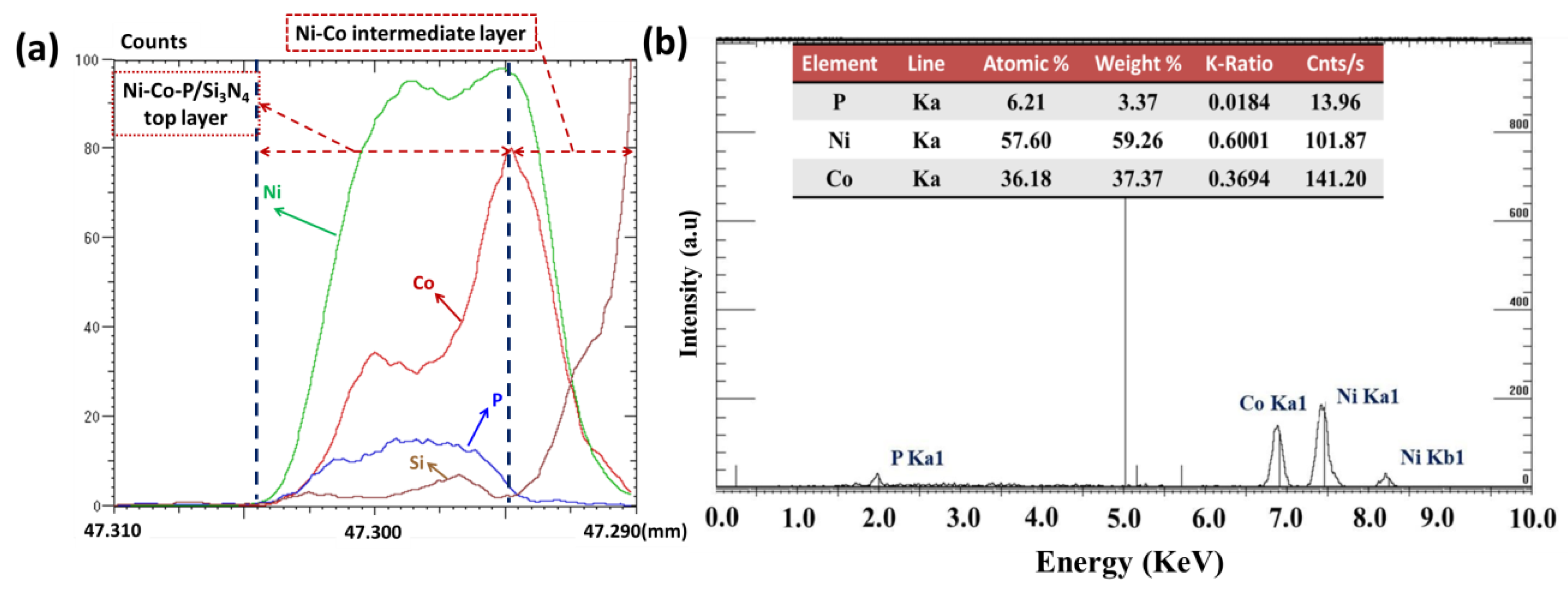
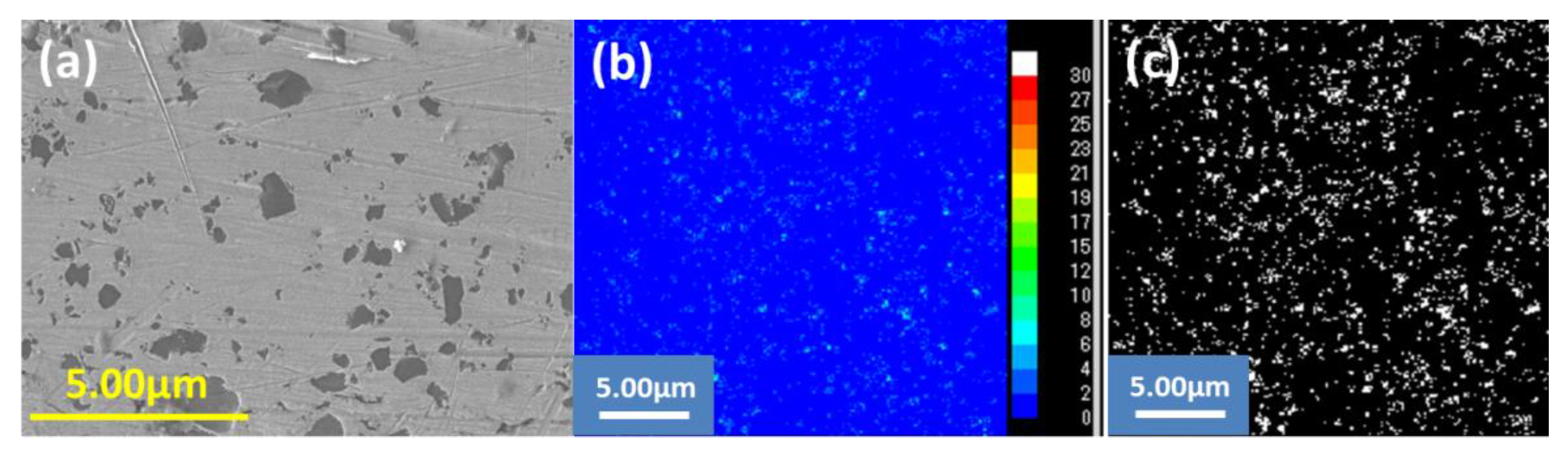
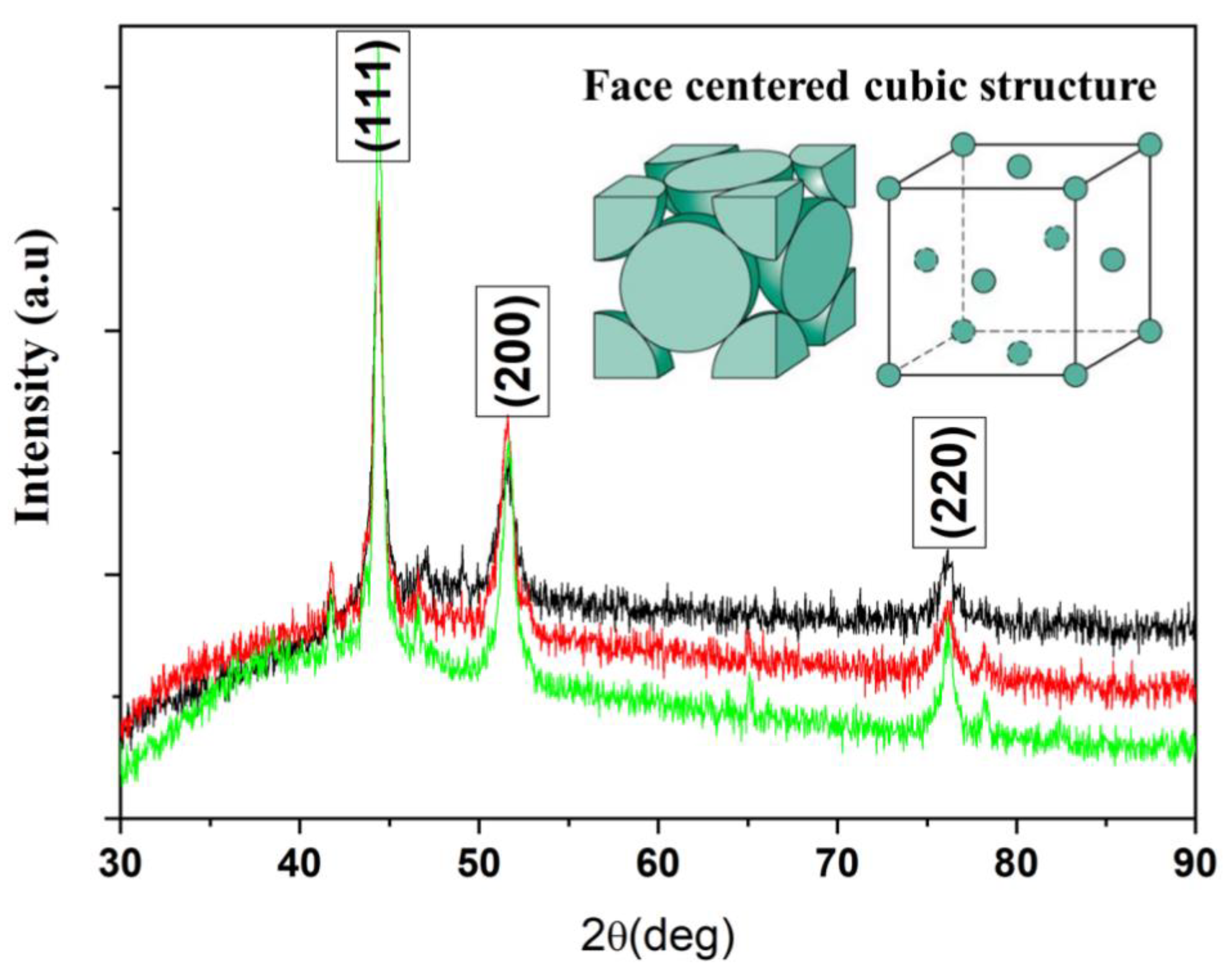
3.1. Chemical Composition and Microstructure Characterization

Figure 1 illustrates the cross-sectional view of a Ni–Co–P/Si3N4 composite coating over a silicon-aluminum substrate. This type of Ni–Co–P/Si3N4 composite coating is 16 µm thick in total, as shown in Figure 1a. There appears to be no obvious contrast between the intermediate Ni–Co layer and the upper Ni–Co–P/Si3N4 composite layer in Figure 1b. Since the whole coating composition primarily consisted of nickel and cobalt elements, which have similar atomic numbers, the two layers did not differ. A careful view was given to the connection region between the adhesive Ni–Co intermediate and the Al–Si substrate, but no defect-like cracking was visible. This microscopic characterization well confirmed that rapid deposition of the Ni–Co intermediate layer greatly improved the coating adhesion onto the Al–Si substrate.
However, the top Ni–Co–P/Si3N4 composite layer, intermediate Ni–Co layer, and substrate were not so different from Figure 1. Accordingly, the elemental depth profiling of the Ni–Co–P/Si3N4 composite coating over the Al–Si substrate is shown in Figure 2a; above the Al–Si substrate was an intermediate layer of nickel and cobalt that improved the growth and orientation of the subsequently deposited Ni–Co–P/Si3N4 composite layer, where the thickness of the intermediate Ni–Co layer was around 5 µm, without any trace of the P element. As for the thickness of the upper Ni–Co–P/Si3N4 composite layer, it was about 10 µm thick, as shown in Figure 2a. The EDS analysis, as shown in Figure 2b, shows the elemental composition of the Ni–Co–P/Si3N4 composite layer, including 59.26 wt.% Ni, 37.37 wt.% Co, and 3.37 wt.% P. Since the distribution of Si3N4 was not homogeneous and its volumetric fraction was minimal within the electroplated Ni–Co–P matrix, the weight concentration of the Si3N4 indicated by the SEM/EDS characterization is inaccurate and not applicable for the determination of the exact number of Si3N4 particles.
Consequently, EPMA was applied to measure the silicon element within the ROI region of the top layer. As shown in Figure 3a, the silicon mapping was obtained and processed with 1.52a Image J software (National Institutes of Health (NIH). However, as indicated in Figure 3b, an agglomeration of Si3N4 particles was present within the resulting Ni–Co–P/Si3N4 composite coating. In this study, the nano-sized Si3N4 particles were directly dispersed within the electrolyte, assisted by the ultrasonic process prior to electroplating; nevertheless, the electrolyte was just mechanically stirred with the magnetic stirrer during electroplating. Thus, a strong agglomeration trend of Si3N4 particles occurred due to their high activity. The volumetric fraction of Si3N4 particles is distinguished from the upper Ni–Co–P/Si3N4 composite layer in Figure 3b; by assuming that Si3N4 was the single hardening phase in the Ni–Co–P matrix, the volumetric fraction of the Si3N4 particles was calculated to be about 7.35%.
Figure 4 shows the XRD spectra of three electrodeposited Ni–Co–P/Si3N4 composite coatings prepared under the same conditions. This indicates there is no distinct difference in crystalline structure among the resulting three electrodeposited Ni–Co–P/Si3N4 composite coatings. In this study, the weight concentration of the cobalt element was around 37.37%; thus, Ni–Co–P/Si3N4 composite coatings are commonly regarded as a solution of cobalt and phosphorus alloying elements on a nickel base, which leads to lattice distortion [15,16,17]. As reported in the literature, the addition of Si3N4 to the resulting Ni–Co–P composite coating reduces the hydrogen atoms, leading to defects in the lattice [18]. With the dispersion of Si3N4 in the electrolyte, the (111) peak becomes intense, which relates to the change in Co content in the composite coatings. This means the presence of Si3N4 particles facilitates the preferential deposition of Co in the composition coating [19]. Those aspects result in the lattice distortion of nickel.
As shown in Figure 4, the three representative peaks corresponding to the (111), (200) and (220) crystallographic planes of the Ni–Co solid solution were distinct. Among them, the (111) crystal surface was very intense, which indicates a crystal orientation toward the direction [111] during electroplating, which is assigned to the face-centered cubic (FCC) crystals. In the FCC crystalline system, the surface energy of the (111) plane was lower than that of the (220) plane, the (111) plane had a higher atomic density as compared with those of the other two planes. Therefore, Ni and Co atoms would migrate from the higher energy states of the (220) plane to the lower energy of the (111) plane during annealing; as a result, the production of Ni–Co grains with random crystallographic orientations and textures occurred, which is consistent with previously reported results [20,21]. In the case of the (200) plane, its intensity remained constant—there were no significant changes in the grain growth direction. Additionally, relatively lower diffraction peaks located at 41.7° and 46.6° were observable, which are reportedly assigned to stable a BCT-Ni3P phase that originates from the dissolution of P into nickel grains, forming an intermetallic Ni3P precipitation [22]. It has been reported that such precipitation plays a strengthening role in anti-friction and anti-wear [23]. Thus, the resulting composite coating involves a dominant FCC structure mixed with a minor BCT-Ni3P phase.

3.2. Mechanical Properties

The micro-hardness of the Al–Si alloy and the Ni–Co–P/Si3N4 coated specimen was 221 ± 11 HV200g and 473 ± 24 HV200g, respectively. The results clearly reveal that the resulting Ni–Co–P/Si3N4 composite coating exhibited a hardness value at least two times higher that of the silicon aluminum substrate, which is comparable with existing data from Ni–Co–P composite coatings [10]. Figure 5 shows the indented traces on the coated specimen under different indentation loads. Ni–Co–P/Si3N4 composite coating does not display obvious indentation-induced cracks and collapse. Thus, the Ni–Co–P/Si3N4 composite coating is tough and thus sustains a higher loading capacity.
As for the mechanical strength of the Ni–Co–P/Si3N4 composite coating, it has been claimed to be due to both the matrix and to strengthening solids [24]. Solid particles generally play a strengthening role, supporting the matrix and resisting deformation. During the electroplating process, a considerable improvement in mechanical strength primarily results from grain nucleation and grain refining, owing to the dispersion of solid particles in metallic matrix [10]. In this study, phosphorus was involved, which resulted in the formation of intermetallic Ni3P during the annealing process, thereby yielding a hardening effect due to precipitation [25]. Thus, the above-mentioned influential aspects were responsible for the comprehensive mechanical properties of the resulting Ni–Co–P/Si3N4 composite coating in this study.
The adhesion strength of the Ni–Co–P/Si3N4 composite coating over the Al–Si substrate was measured by micro-scratching testing. As shown in Figure 6a, the adhesion strength was defined as the critical load of 37N for the resulting Ni–Co–P/Si3N4 composite coating, where a sudden drop in friction occurred. At this point, the whole coating was scratched off. Figure 6,c show an optical observation of the scratch track. Within the scratch trace, ploughs and deformation phenomenon were present, without observable cracking or fracturing—as shown in Figure 6b. However, some defects are visible in Figure 6c, at a magnification higher than that in Figure 6b. This implies that the densification of the Ni–Co–P/Si3N4 composite coating should be further improved.

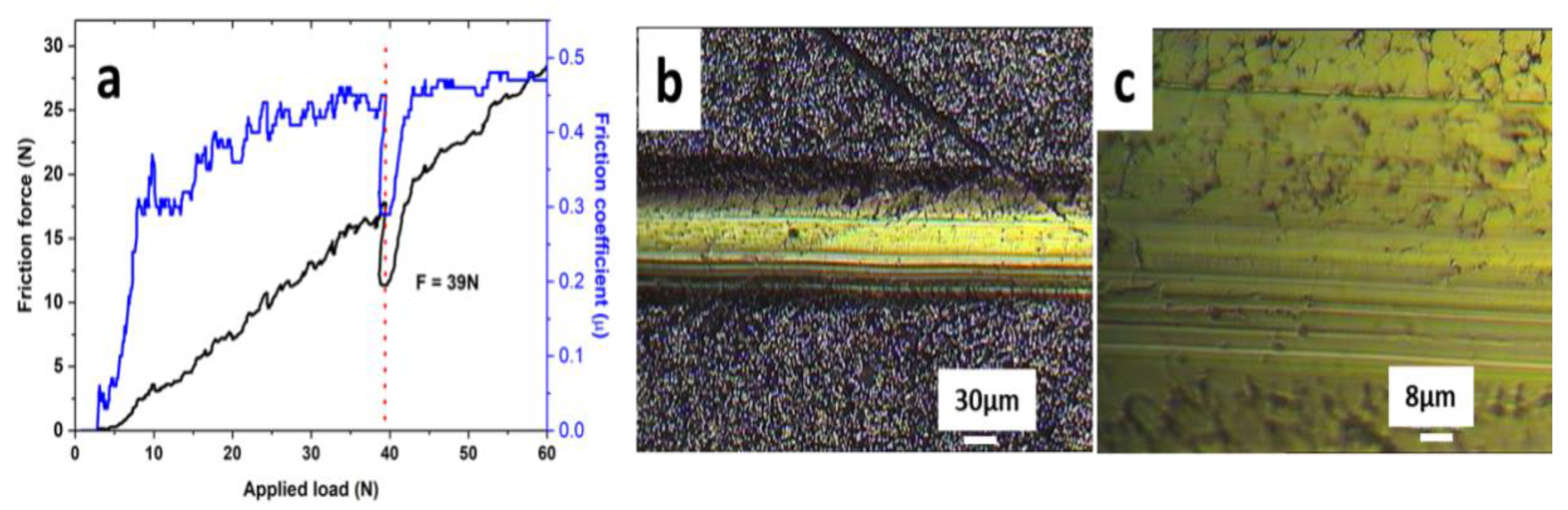
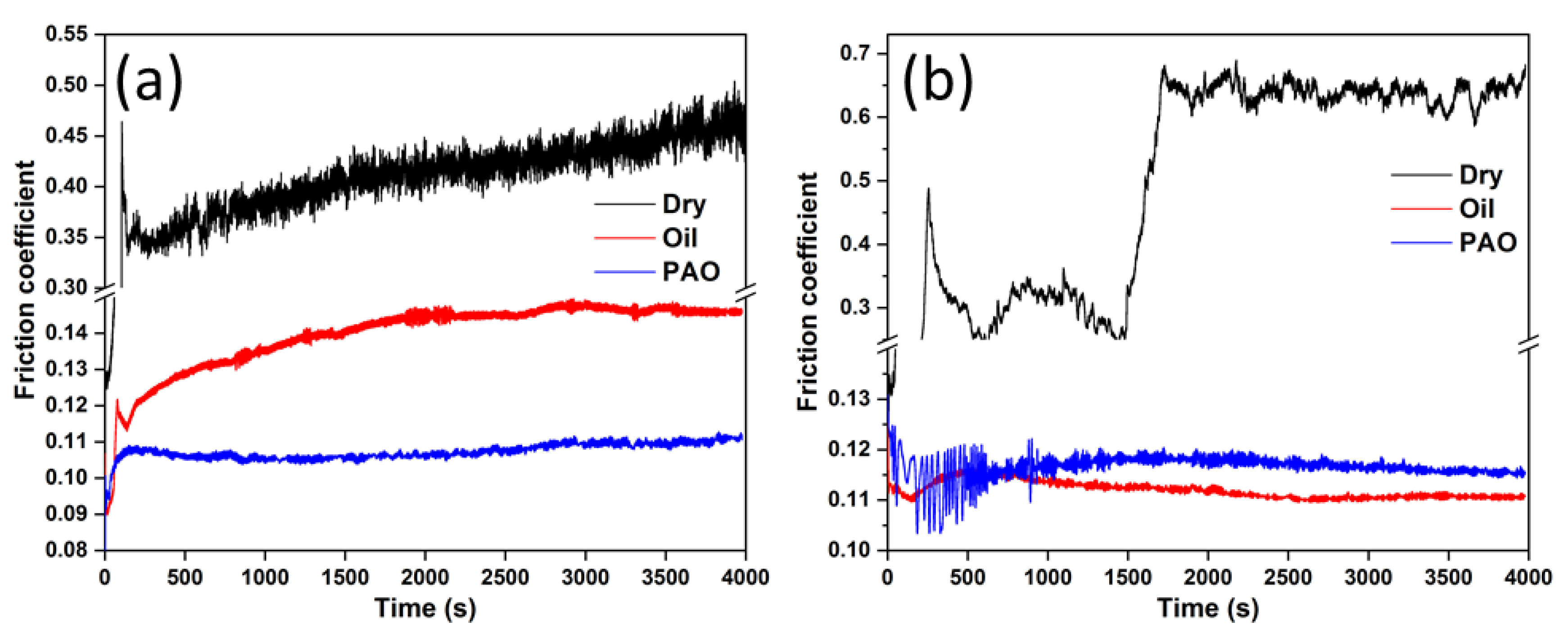
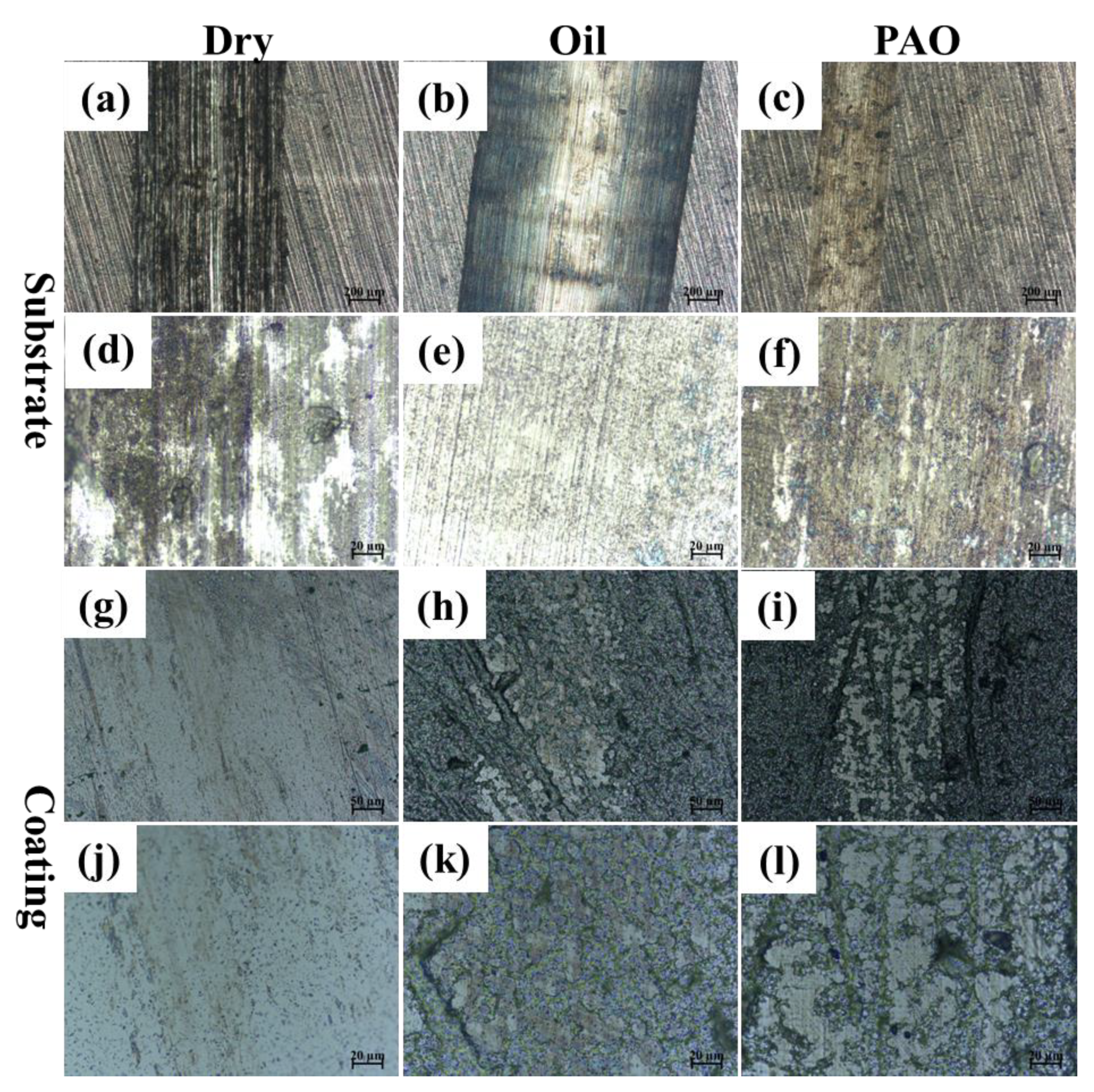
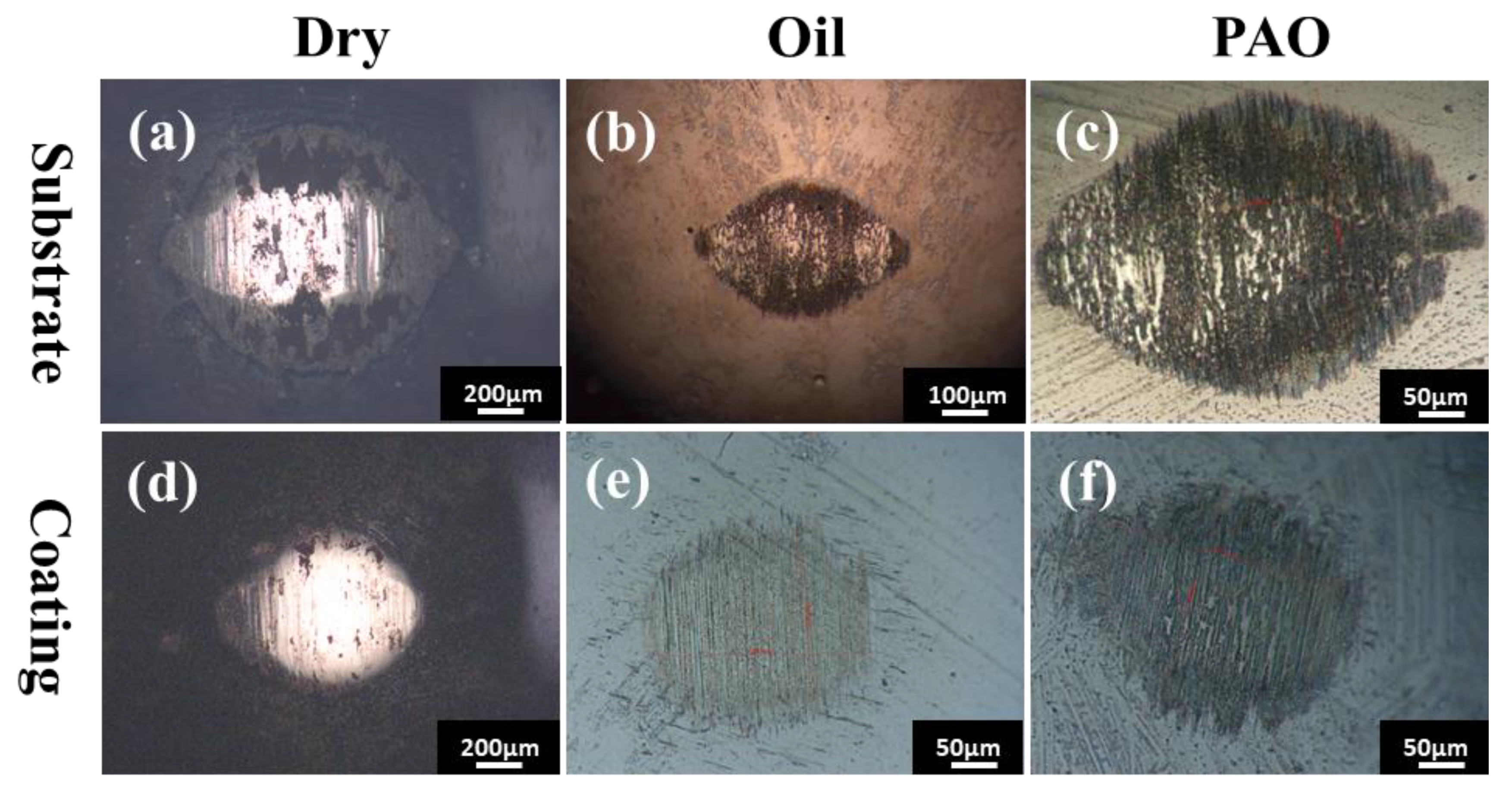
3.3. Tribological Properties of the Ni–Co–P/Si3N4 Composite Coating

The friction and wear behaviors of the Ni–Co–P/Si3N4 composite coating under dry and lubricated conditions with PAO and engine oil were investigated to ascertain the suitability of surface hardening for moving components, in reference to the Al–Si substrate. As shown in Figure 7a,b, under dry sliding, friction gradually increased for the Al–Si substrate as sliding occurred, whereas the Ni–Co–P/Si3N4 composite coating exhibited unexpected worse friction after running for 25 min—the friction coefficient even rose up to 0.7. When comparing the friction results of the samples lubricated with PAO and engine oil, both the Al–Si substrate and Ni–Co–P/Si3N4 specimen demonstrated favorably stable friction, with a friction coefficient of about 0.12.
It is noted that, when the friction pairs were lubricated with engine oil, the friction adversely displayed a considerable increase for the Al–Si substrate in Figure 7a. When adopting PAO as the lubricant, a relative stable friction curve occurred for the Al–Si substrate. This implies that the engine oil involved in this study was not compatible with the Al–Si surface. For the Ni–Co–P/Si3N4 composite coating, when applying engine oil as the lubricant, the friction coefficient further decreased, as shown in Figure 7b. Thus, the presence of the Ni–Co–P/Si3N4 composite coating favored the reduction of friction.
In this study, a ball-on-flat reciprocating tribometer was adopted to measure the wear loss. Figure 8 displays the specific wear rates of the Al–Si substrate and the Ni–Co–P/Si3N4 composite coating under different conditions. It was found that the Ni–Co–P/Si3N4 composite coating reduced wear significantly—by two levels of magnitude as compared to the Al–Si substrate. When observing the wear results of the Al–Si substrate specimen under dry and lubricated conditions in Figure 8a, when the PAO was present between the rubbing contacts, a significant reduction of wear occurred. However, the presence of engine oil did not function effectively to inhibit wear, adversely producing a worsening of wear. The material loss of the Ni–Co–P/Si3N4 composite coating varied considerably in different situations (Figure 8b), where relatively high wear occurred during dry sliding; PAO performed very well, and applying engine oil caused a slight increase in wear as compared to PAO. However, the role of Si3N4 in the tribological behavior of the resulting Ni–Co–P composite coating is not investigated in this study. The existing literature has shown that mixing hardening Si3N4 particles into a Ni–Co–P alloyed matrix greatly improves the wear resistance of Ni–Co–P coatings [11,26]. Thus, addition of Si3N4 as a hardening phase in alloyed Ni–Co–P coatings protects the Al–Si substrate from wear.
The optical images in Figure 9 exhibit the topographical features of wear tracks at 100 times zoom, where the dimension of the wear tracks on electroplated Ni–Co–P/Si3N4 composite coating surfaces (Figure 9g–i) are observed to be much smaller and shallower than those of the Al–Si substrate surface (Figure 9a–c), whether under dry conditions or lubrication with PAO40 or engine oil. According to the topographical features of the worn Al–Si substrate at higher magnifications of the corresponding wear tracks (Figure 9a–c), the wear mechanisms were severe abrasive wear and deformation, regardless of the lubricating conditions—as shown in Figure 9d–f—which is consistent with the reported tribological characteristics of aluminum alloys in comparison to steel [27]. In comparison, the Ni–Co–P/Si3N4 composite coating showed mild abrasive wear, with distinguishable wear tracks parallel to the sliding direction in Figure 9j–l.
According to the specific wear rates in Figure 8, PAO was the best lubricant in this study. When measuring the worn profile, the wear of the Ni–Co–P/Si3N4 composite coatings was not readily measured. From the optical observation, some scratch traces are visible in Figure 9h, which is due to the action of an occasional wear particle that became entrapped between the sliding surfaces. Regarding the engine oil, it performed similarly (Figure 9i) between the rubbing contacts.
As shown in Figure 10a, abrasive grooves were visible in the wear scars during dry sliding. Material transfer appeared in the form of scatter debris and was later sheared to the surrounding edges of the wear scar. In Figure 10d, the wear scar featured as grooves and scratches without gross material transfer, typical of abrasion [28]. When applying PAO as the lubrication medium, wear scars showed signs of mild abrasion with slight grooves, with no lump generated (Figure 10b,e). As engine oil lubricated the rubbing contacts, the wear track was characterized by mild abrasion, as shown in Figure 10c,f.

4. Conclusions

The microstructure, mechanical, and tribological behaviors of Ni–Co–P/Si3N4 composite coatings prepared using an electroplating process were reported in this study. The rapid deposition of the Ni–Co intermediate layer made a significant contribution towards the sufficiently high adhesion of the resulting Ni–Co–P/Si3N4 composite coating over the Al–Si substrate. The presence of a Ni–Co–P/Si3N4 composite coating increased the substrate hardness by at least two times. In particular, the Ni–Co–P/Si3N4 composite coating demonstrated significant resistance to wear under both dry and lubricated conditions.

Author Contributions

Writing—original draft preparation, Z.L.; formal analysis, F.M.; investigation, D.L. and G.G.; writing—review and editing, S.W.; supervision, F.M. and S.W.; project administration, S.W. and L.G.; funding acquisition, G.Y. All authors have read and agreed to the published version of the manuscript.

Funding

This research was funded by the Science Fund of State Key Laboratory of Engine Reliability (No. SLER-201906), and also received support from the National Natural Science Foundation of China (No. 51575505).

Data Availability Statement

Not applicated.

Conflicts of Interest

The authors have no known competing financial interest or personal relationships that could have appeared to influence the work reported in this paper.

References

  1. Tisza, M.; Czinege, I. Comparative study of the application of steels and aluminum in lightweight production of automotive parts. Int. J. Lightweight Mater. Manuf. 2018, 1, 229–238. [Google Scholar]
  2. Du, F.; Li, C.; Mi, Z.; Shen, Y.; Huang, R.; Han, X.; Dong, Y.; Xu, J. Anti-wear property of aluminum-silicon alloy treated by chemical etching. Mech. Honing Laser Finish. Mater. 2019, 18, 1273. [Google Scholar] [CrossRef] [Green Version]
  3. Sun, H.; Li, A.; Zhou, Y.; Liao, X.; Ge, D. Dry wear characteristics of machined ZL109 aluminum-silicon alloy surface under unidirectional and reciprocating rolling-contact friction. Surf. Topogr. Metrol. Prop. 2019, 8, 015001. [Google Scholar] [CrossRef]
  4. Osipov, V.N.; Fadin, Y.A.; Nikanorov, S.P. Wear and Coefficient of Friction of a Supermodified Hypereutectic Aluminum–Silicon Alloy. Tech. Phys. 2020, 65, 1981–1986. [Google Scholar] [CrossRef]
  5. Zhang, X.; Qin, J.; Das, M.K.; Hao, R.; Zhong, H.; Thueploy, A.; Limpanart, S.; Boonyongmaneerat, Y.; Ma, M.; Liu, R. Co-electrodeposition of hard Ni-W/diamond nanocomposite coatings. Sci. Rep. 2016, 6, 22285. [Google Scholar] [CrossRef]
  6. Kundu, S.; Das, S.K.; Sahoo, P. Friction and wear behavior of electroless Ni-P-W coating exposed to elevated temperature. Surf. Interfaces 2019, 14, 192–207. [Google Scholar] [CrossRef]
  7. Duari, S.; Mukhopadhyay, A.; Barman, T.K.; Sahoo, P. Study of wear and friction of chemically deposited Ni-P-W coating under dry and lubricated condition. Surf. Interfaces 2017, 6, 177–189. [Google Scholar] [CrossRef]
  8. Xu, Y.; Zheng, X.; Hu, X.; Yin, Y.; Lei, T. Preparation of the electroless Ni–P and Ni–Cu–P coatings on engine cylinder and their tribological behaviors under bio-oil lubricated conditions. Surf. Coat. Technol. 2014, 258, 790–796. [Google Scholar] [CrossRef]
  9. Liew, K.; Chia, S.; Kok, C.; Low, K. Evaluation on tribological design coatings of Al2O3, Ni–P–PTFE and MoS2 on aluminium alloy 7075 under oil lubrication. Mater. Des. 2013, 48, 77–84. [Google Scholar] [CrossRef]
  10. Lelevic, A.; Walsh, F.C. Electrodeposition of Ni P composite coatings: A review. Surf. Coat. Technol. 2019, 378, 124803. [Google Scholar] [CrossRef] [Green Version]
  11. Matik, U. Structural and wear properties of heat-treated electroless Ni-P alloy and Ni-P-Si3N4 composite coatings on iron based PM compacts. Surf. Coat. Technol. 2016, 302, 528–534. [Google Scholar] [CrossRef]
  12. Sarkar, S.; Baranwal, R.K.; Lamichaney, S.; De, J.; Majumdar, G. Optimization of electroless Ni-Co-P coating with hardness as response parameters: A computational approach. J. Tribol. 2018, 18, 81–96. [Google Scholar]
  13. Shi, L.T.; Hu, J.; Fang, L.; Wu, F.; Xiao, X.L.; Meng, F.M. Effects of cobalt content on mechanical and corrosion properties of electroless Ni-Co-P/TiN nanocomposite coatings. Mater. Corros. 2016, 67, 1034–1041. [Google Scholar] [CrossRef]
  14. Mallory, G.O.; Hajdu, J.B. Electroless Plating, American Electroplaters and Surface Finishers Society, Orlando, Fla; AESF: New York, NY, USA, 1990; pp. 196–201. [Google Scholar]
  15. Ma, C.; Wang, S.C.; Wang, L.P.; Walsh, F.C.; Wood, R.J.K. The electrodeposition and characterization of low-friction and wear-resistant Co-Ni-P coatings. Surf. Coat. Technol. 2013, 235, 495–505. [Google Scholar] [CrossRef]
  16. Zhang, Y.; Kang, M.; Yao, L.; Mbugua, N.S.; Jin, M.; Zhu, J. Study on the Wear and Seawater Corrosion Resistance of Ni–Co–P Alloy Coatings with Jet Electrodeposition in Different Jet Voltages and Temperatures of Plating Solution. Coatings 2020, 10, 639. [Google Scholar] [CrossRef]
  17. Ren, L.; Cheng, Y.; Wang, Q.; Yang, J. Study on the properties of Ni-W-P coating with PTFE co-deposition. Surf. Topogr. Metrol. Prop. 2019, 7, 045009. [Google Scholar] [CrossRef]
  18. Humam, S.B.; Gyawali, G.; Joshi, B.; Kim, T.H.; Lee, S.W. Influence of WC and TaC particles on the microstructure and scratch resistance of electrodeposited nickel-tungsten alloy. J. Alloys Compd. 2021, 893, 162371. [Google Scholar] [CrossRef]
  19. Jiang, W.; Shen, L.D.; Xu, M.Y.; Wang, Z.W.; Tian, Z.J. Mechanical properties and corrosion resistance of Ni-Co-SiC composite coatings by magnetic field-induced jet electrodeposition. J. Alloys Compd. 2019, 791, 847–855. [Google Scholar] [CrossRef]
  20. Arora, S.; Kumari, N.; Srivastava, C. Microstructure and corrosion behavior of NiCo-Carbon nanotube composite coatings. J. Alloys Compd. 2019, 801, 449–459. [Google Scholar] [CrossRef]
  21. Karslioglu, R.; Akbulut, H. Comparison microstructure and sliding wear properties of nickel–cobalt/CNT composite coatings by DC, PC and PRC current electrodeposition. Appl. Surf. Sci. 2015, 353, 615–627. [Google Scholar] [CrossRef]
  22. Aliofkhazraei, M.; Aliofkhazraei, M.; Walsh, F.C. A review of electrodeposited Ni-Co alloy and composite coatings: Microstructure, properties and applications. Surf. Coat. Technol. 2019, 372, 463–498. [Google Scholar] [CrossRef]
  23. Karimzadeh, A.; Rouhaghdam, A.S.; Aliofkhazraei, M.; Miresmaeili, R. Sliding wear behavior of Ni–Co–P multilayer coatings electrodeposited by pulse reverse method. Tribol. Int. 2020, 141, 105914. [Google Scholar] [CrossRef]
  24. Ghavidel, N.; Allahkaram, S.R.; Naderi, R.; Barzegar, M.; Bakhshandeh, H. Corrosion and wear behavior of an electroless Ni-P/nano-SiC coating on AZ31 Mg alloy obtained through environmentally-friendly conversion coating. Surf. Coat. Technol. 2020, 382, 125156. [Google Scholar] [CrossRef]
  25. Wang, Q.; Callisti, M.; Greer, J.; McKay, B.; Milickovic, T.K.; Zoikis-Karathanasis, A.; Deligkiozi, I.; Polcar, T. Effect of annealing temperature on microstructure, mechanical and tribological properties of nano-SiC reinforced Ni-P coatings. Wear 2016, 356–357, 86–93. [Google Scholar] [CrossRef] [Green Version]
  26. Dhakal, D.R.; Kshetri, Y.K.; Gyawali, G.; Kim, T.-H.; Choi, J.-H.; Lee, S.W. Understanding the effect of Si3N4 nanoparticles on wear resistance behavior of electroless Nickel-Phosphorus coating through structural investigation. Appl. Surf. Sci. 2020, 541, 148403. [Google Scholar] [CrossRef]
  27. Decrozant-Triquenaux, J.; Pelcastre, L.; Prakash, B.; Hardell, J. Influence of lubrication, tool steel composition, and topography on the high temperature tribological behavior of aluminum. Friction 2021, 9, 155–168. [Google Scholar] [CrossRef]
  28. Peng, Y.; Xu, Y.; Geng, J.; Dearn, K.D.; Hu, X. Tribological assessment of coated piston ring-cylinder liner contacts under bio-oil lubricated conditions. Tribol. Int. 2017, 107, 283–293. [Google Scholar] [CrossRef]
Figure 1. The cross-sectional view (a) of a Ni–Co–P/Si3N4 composite coating over a silicon aluminum alloy, (b) a higher magnification view of selected area in (a).
Metals 12 00120 g001
Figure 2. Elemental depth profiling across a Ni–Co–P/Si3N4 composite coating over an Al–Si substrate by EPMA (a) and elemental composition of a Ni–Co–P/Si3N4 composite coating over an Al–Si substrate by SEM/EDS (b).
Metals 12 00120 g002
Figure 3. EPMA/EDS mapping of the silicon element within the ROI region (a,b) and the corresponding volumetric fraction of Si3N4 within the Ni–Co–P matrix after Image J processing (c).
Metals 12 00120 g003
Figure 4. XRD pattern of three Ni–Co–P/Si3N4 composite specimens prepared under the same conditions.
Metals 12 00120 g004
Figure 5. Indentation track of the Ni–Co–P/Si3N4 composite coating.
Metals 12 00120 g005
Figure 6. (a) The curve of friction and the corresponding friction coefficient versus the applied load during the scratching process, (b) Optical images of scratching tracks of the Ni–Co–P/Si3N4 composite coating, (c) Optical image of the scratching tracks at a higher magnification than (b).
Metals 12 00120 g006
Figure 7. Variation of the friction curves with sliding time for the Al–Si substrate (a) and the Ni–Co–P/Si3N4 composite coated specimen, under dry conditions and lubrication with PAO and engine oil (b).
Metals 12 00120 g007
Figure 8. Specific wear rates of Al–Si substrate (a) and (b) Ni–Co–P/Si3N4 composite coated specimens under dry conditions and lubrication with PAO and engine oil.
Metals 12 00120 g008
Figure 9. Optical observation of worn traces (af) over Al–Si substrates and (gl) Ni–Co–P/Si3N4 composite coated specimens under dry conditions and with lubrication with PAO and engine oil.
Metals 12 00120 g009
Figure 10. Optical observation of wear scars from GCr15 balls on Al–Si substrates (ac) and Ni–Co–P/Si3N4 composite coated specimens (df) under dry conditions and with lubrication with PAO and engine oil.
Metals 12 00120 g010
Publisher’s Note: MDPI stays neutral with regard to jurisdictional claims in published maps and institutional affiliations.

