Article

Heterogeneous Microstructure-Induced Creep Failure Responses in Various Sub-Zones of Modified 310S Welded Joints

1
Key Laboratory of Nuclear Materials and Safety Assessment, Institute of Metal Research, Chinese Academy of Sciences, Shenyang 110016, China
2
School of Materials Science and Engineering, University of Science and Technology of China, 72 Wenhua Road, Shenyang 110016, China
*
Author to whom correspondence should be addressed.
Metals 2022, 12(1), 116; https://doi.org/10.3390/met12010116
Submission received: 13 December 2021 / Revised: 4 January 2022 / Accepted: 5 January 2022 / Published: 7 January 2022
(This article belongs to the Special Issue Welding and Fatigue of Railway Metallic Materials)

Abstract

:
In order to reveal the creep failure behavior of novel modified 310S austenite steel welded joints, the creep life and microstructure evolution of the 310S austenite steel welded joints were investigated in this study. The rupture life was assessed to estimate the damage of the welded joint based on creep rupture tests performed at 600 °C in the stress range of 170–238 MPa. Compared with WM, HAZ facilitated the occurrence of creep failure in long term creep due to the combination of a smaller hardness value, a more heterogenous microstructure accompanied by coarsened M23C6, a larger grain size, higher KAM and Schmid factor. Discontinuous Laves phases appeared near the boundaries between the δ-ferrite and γ-austenite grains in the WM, and dislocation strengthening and precipitation strengthening were observed near the boundary in the BM. Furthermore, segregation elements were detected by APT and EDS adjacent to the boundary. Cr and C segregation near grain boundaries weaken the creep resistance in long term creep service.

1. Introduction

AISI 310S austenitic stainless steel is one of the most promising materials for use in the key components of nuclear power plants or chemical industries, owing to its prominent comprehensive properties, such as excellent high temperature creep resistance and corrosion resistance [1,2]. However, owing to the inherent microstructure heterogeneity, the 310S welded joints are easily subject to premature failure during creep service at elevated temperatures for long periods. Some of the literature is focused on the failure behavior of welded joints [3,4]. Therefore, the creep failure of welded joints is essential.
Since the 310S welded joint in nuclear power plants is intended to service above 600 °C in its design application, the properties of creep deformation and rupture are crucial to service life and safety [5]. Despite wrought development, premature failure attributed to welded joints has plagued the nuclear power industry for decades, and there is still no proper solution. Thus, we should be pay more attention to the creep performance of welded joints at high temperatures. High-temperature creep properties are strongly linked to the nucleation, growth, coarsening and dissolution of different precipitates [6,7]. Precipitation strengthening plays a significant role in creep resistance [8,9]. In stainless steels subjected to elevated temperature, the precipitation of M23C6 and δ-phase particles is considered to be detrimental and can eventually cause cracking of the material [10,11]. Depending on ageing time, precipitation could decrease the yield strength due to the competition between locally reduced solid solution strengthening and precipitation strengthening [12,13,14]. It should be stressed that M23C6 precipitation often plays an important role for the high-temperature materials, such as stainless steels, nickel-based super alloys and other alloys, used in components of super heater boilers and supercritical heat exchangers operating at temperatures above 600 °C [15,16,17]. A cube relationship between the M23C6 precipitates and the matrix of [001] γ|| [001] M23C6 and [110] γ|| [110] M23C6 has been reported, whereby the adjacent grain boundary is likely prompted into nucleation by minimizing the activation energy [18,19,20].
In the normal cases, joint softening, creep cavities and cracks are essential for creep failure during creep exposure [5,21]. Isik et al. found that Laves phase particles were apt to nucleate around M23C6, which implies that the evolution behavior of second-phase particles should be assessed in creep service [22,23]. Liu et al. revealed that the creep failure of 9Cr dissimilar welded joints in an over-tempered zone (OTZ) failed from stress concentration, which was induced by the coarsening of M23C6 in triple grain boundaries [24]. Due to the microstructure heterogeneity of welded joints, the creep failure behavior of welded joints under the service period should be of concern. However, most of the researchers concentrate on creep crack growth and the effect of heat treatment on welded joints [25,26]. Few researchers have paid attention to the fracture behaviors, specifically considering the integrity of welded joints under different applied stresses. Therefore, it is important to assess creep failure behavior in order to systematically explain the creep cracking and rupture failure behaviors of each zone of a 310S welded joint.
Meanwhile, experimental data on the microstructure and rupturing of plasma arc welding (PAW) welded joints under elevated temperature conditions are still scarce. Thus, the purpose of this paper is to make clear the creep failure behavior in each region of a PAW welded joint. In this research, a series of creep experiments were carried out on the welded joints at 600 °C and with a stress range of 238–170 MPa. The evolution of the heterogeneous microstructure was characterized in detail by using optical microscope (OM), scanning electron microscope (SEM), electron back-scattered diffraction (EBSD) and transmission electron microscope (TEM), which could be used to make clear the relation between failure location and crack behavior. The evolution of the heterogeneous microstructure was characterized in detail, and found to be caused by the creep condition. Based on the creep resistance and microstructure characterization, the creep failure behavior of the sub-zones of the 310S welded joint was fully analyzed and clarified. The results acquired from this study could be applied to evaluate the structural integrity of the components, especially the glass curing container.

2. Materials and Testing

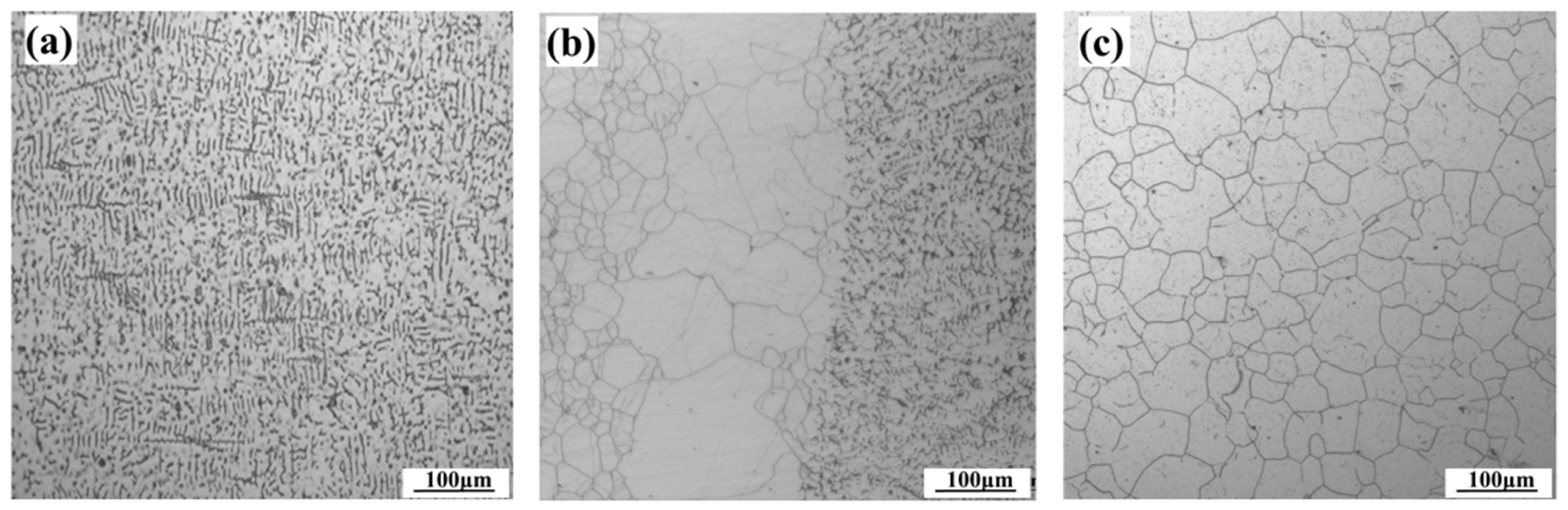
2.1. Materials and Welding Procedure

A 6.5 mm thick X9CrNiSiNCe21-11-2 austenitic stainless steel plate, named modified 310S, was used as the base metal (BM) to produce welded joints via PAW. The filler material was 25Cr-20Ni welding wires, with a diameter of 1.2 mm. The 310S billets were reheated to 1200 °C for 60 min, hot rolled from 50 mm to a 6.5 mm thick plate. The heat-treatment solution condition of the plate is 1050 °C for 20 min, followed by final water quenching. Specimens for the creep rupture test were taken from the plates parallel to the rolling direction. The main chemical compositions of the BM and filler materials are listed in Table 1. PAW procedure was performed by single-layer and single-pass techniques with I-groove and no gap. The welding current was 160 A, welding voltage was 25 V, and the welding speed was 15 mm/s. The 310S welded joint was extracted from a mockup of the welded plate. The 310S welded joint without phase transformation strengthening, and the curing container is not easy to achieve for post weld heat treatment (PWHT). Therefore, the welded joint did not use PWHT in this work. The microstructures are shown in Figure 1. The vermicular ferrite was inserted at the dendritic grain boundaries of the austenite matrix, as shown in Figure 1a. However, the heat affected zone (HAZ) has an obvious border produced by the immense influence of the welding thermal cycle, as shown in Figure 1b. The isometric austenite matrix is shown in Figure 1c. The metallographic differences will manifest different creep resistances. The uniaxial tensile tests were conducted by the SANS-CMT machine (CTMI Co., Ltd, Shenzhen, China). The samples were tested with tensile displacement rates ranging from 0.2 mm/min to 2 mm/min at room temperature and 600 °C. Figure 2 shows that serrations appeared in the stress–deformation curve of the welded joints at 600 °C, indicating that the welded joints experienced dynamic strain aging at this temperature. The values of tensile strength and yield strength were 660 ± 20 MPa and 350 ± 10 MPa at room temperature, and 410 ± 20 MPa and 200 ± 10 MPa at 600 °C, respectively.

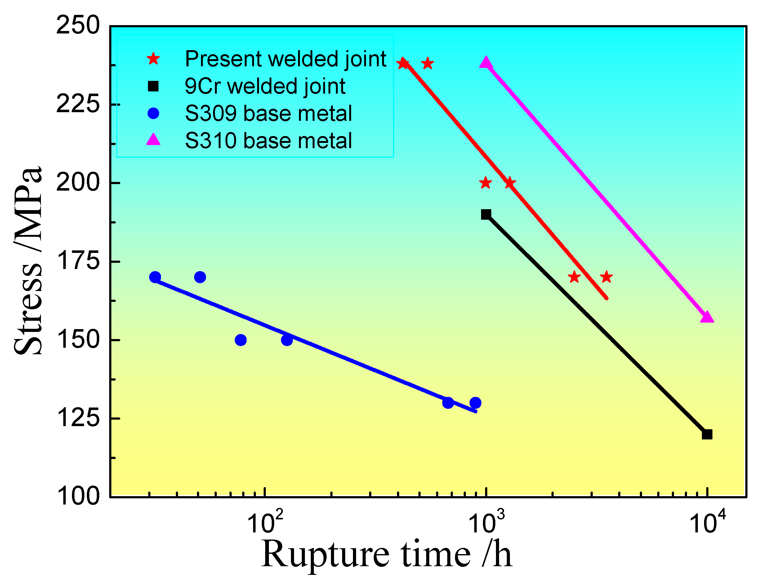
2.2. Creep Experiment

Standard creep rupture specimens, according to the ASTM E139 standard, with a 10 mm × 3 mm cross-section and 50 mm gauge length, were used in this study. The specimens were taken from the BM of the welded joint where the weld metal (WM) was in the middle of the specimen. The creep properties were tested by using a series of uniaxial testing over a series of stresses from 238 MPa to 170 MPa at 600 °C.
The hardness distribution, creep cracking and microstructure evolution were also assessed in the creep evaluation. The secondary phases, mainly the M23C6 and Laves phases, were given special attention in the microstructure analysis of the welded joints. An etching reagent consisting of 10% oxalic acid was used to reveal the austenite and ferrite phases. The micro-hardness measurements were carried out on sections perpendicular to the welding direction, with a load of 1 kg for 13 s, to evaluate the micro-hardness distribution of the welded joints. Subsequently, the microstructures were characterized by using a Zeiss Axio Observer Z1 (Zeiss, Jena, Germany), an FEI QUANTA 450 (FEI, USA), and an EBSD (ZEISS MERLIN Compact, Jena, Germany). Chemical composition analysis of phases was performed by atom probe tomography (LEAP 4000, APT, France). Moreover, TEM (FEI Tecnai G2 20, Hillsboro, ORE, USA) was employed to acquire more details of the precipitates in the creep microstructure.

3. Experimental Results and Analysis

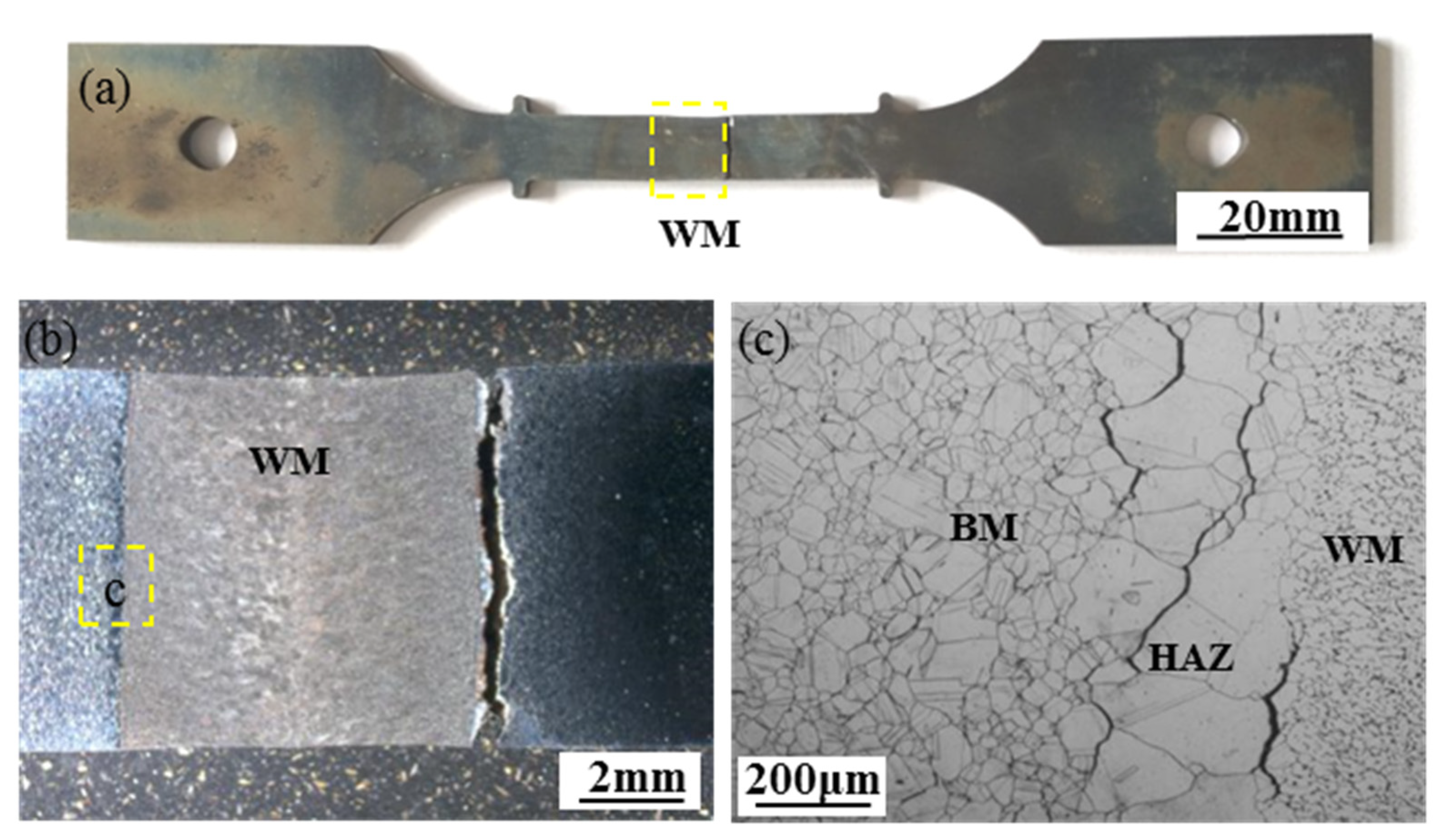
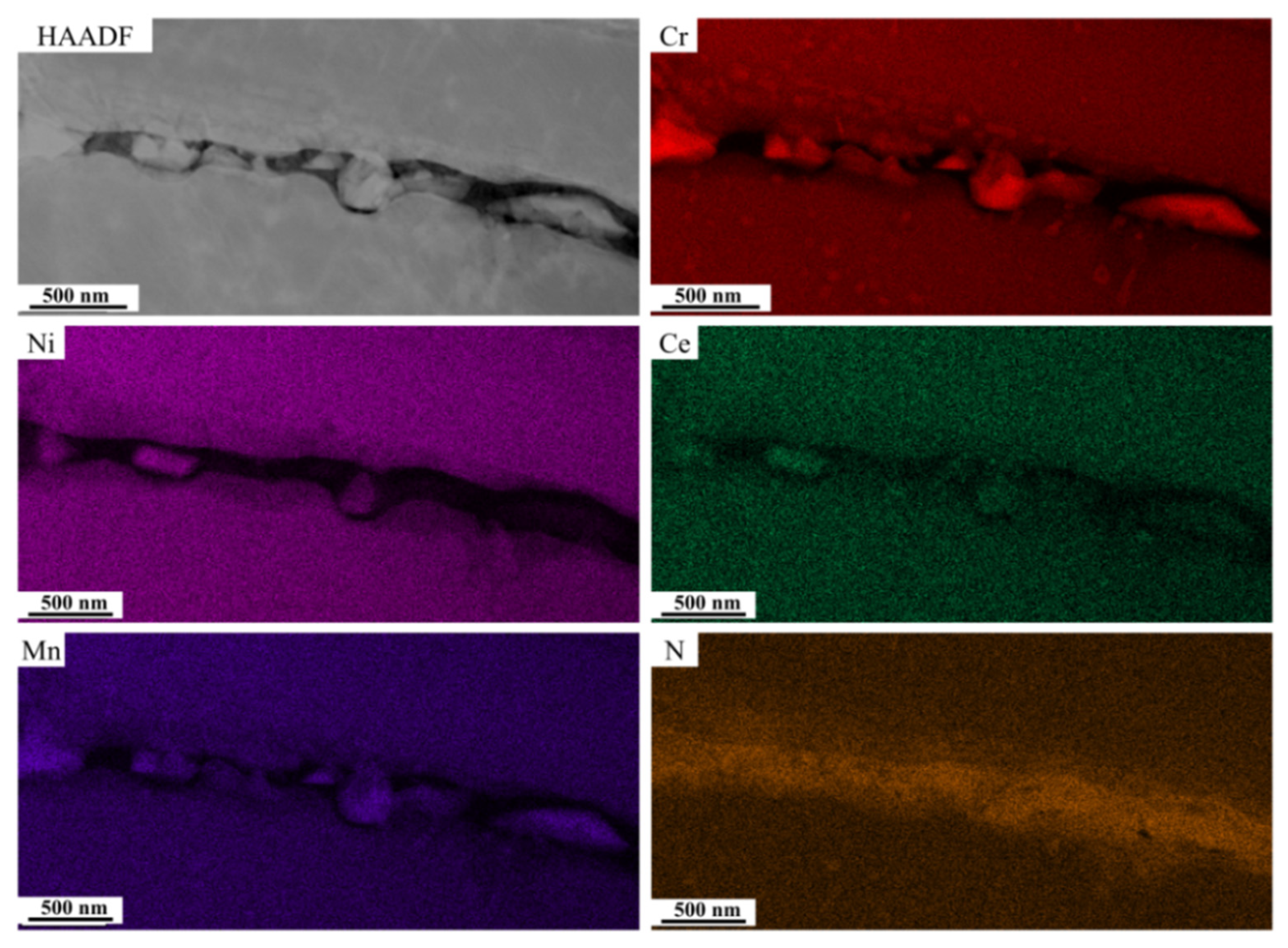
3.1. Fracture Location and Morphology

To detect the creep properties of 310S welded joints, the creep rupture life was explored under the tensile stresses from 238 MPa to 170 MPa at 600 °C, as shown in Figure 3. Creep rupture occurred in HAZ under different stress loads.
Creep rupture tests were further conducted at 600 °C under stresses of 238 MPa and 170 MPa, respectively. After the creep tests, the creep lives were determined to be 430 h and 3504 h, respectively. Figure 4 shows the macroscopic and microscopic profiles of the 310S weld after creep rupture. The fracture location is visible in the HAZ of the welded joints. In the rupture specimen, creep deformation and necking phenomena were not observed under the stress of 238 MPa, as shown in Figure 4a,b. To reveal the cracking evolution during the creep process, the microstructure of the creep fracture is shown in Figure 4c. It can be seen that many secondary cracks appear in the HAZ, which should be responsible for the creep rupture. Cracking is generated from the micro-cracks that form along the austenite grain boundaries, and its direction tends to be perpendicular to the loading direction, as shown in Figure 4c.
Long term service at a high temperature induces stress relaxation cracking (SRC) in the heat affected zone of the austenitic stainless steel [29]. Figure 5 shows the fracture morphologies of two creeps rupture specimens at 600 °C under 238 MPa and 170 MPa, as observed by SEM. Figure 5a shows the macro-profile of the specimen under 238 MPa for 430 h. A large cavity is observed on the fracture in Figure 5b. The cavities are apt to form cracks and accelerate the cracking during creep. Few dimples are found around the cavities, and it can be concluded that the fracture is mixed type under 238 MPa. Figure 5c,d present the fracture features of the long-term specimen subjected to 170 MPa for 3504 h. The fracture has a smooth edge and gray particles adhere to its surface. The fracture type is estimated as mixed type fracture with less ductility. Intergranular cracks could be found on the fracture of the long term creep specimen. It was reported that cracks are easier to initiate and propagate along the noncoherent M23C6/γ interface [30]. Consequently, the cracks grew and coalesced to form intergranular cracking under the creep service.
Given that creep cracking is dominated by stress, failure should occur in the lower-resistance creep section. In general, the hardness value is positively correlated with the resistance to plastic deformation [27]. Figure 6 illustrates the micro-hardness results of the welded joint. It can be seen that the micro-hardness value gradually decreases as the distance increases from the WM center. The maximum micro-hardness value of 198 HV appears in the WM. As the distance increases, the micro-hardness decreases from the WM center, while the HAZ presents the lowest micro-hardness value of 178 HV. Compared with the micro-hardness of the welded joint, the fracture location is considered as HAZ.

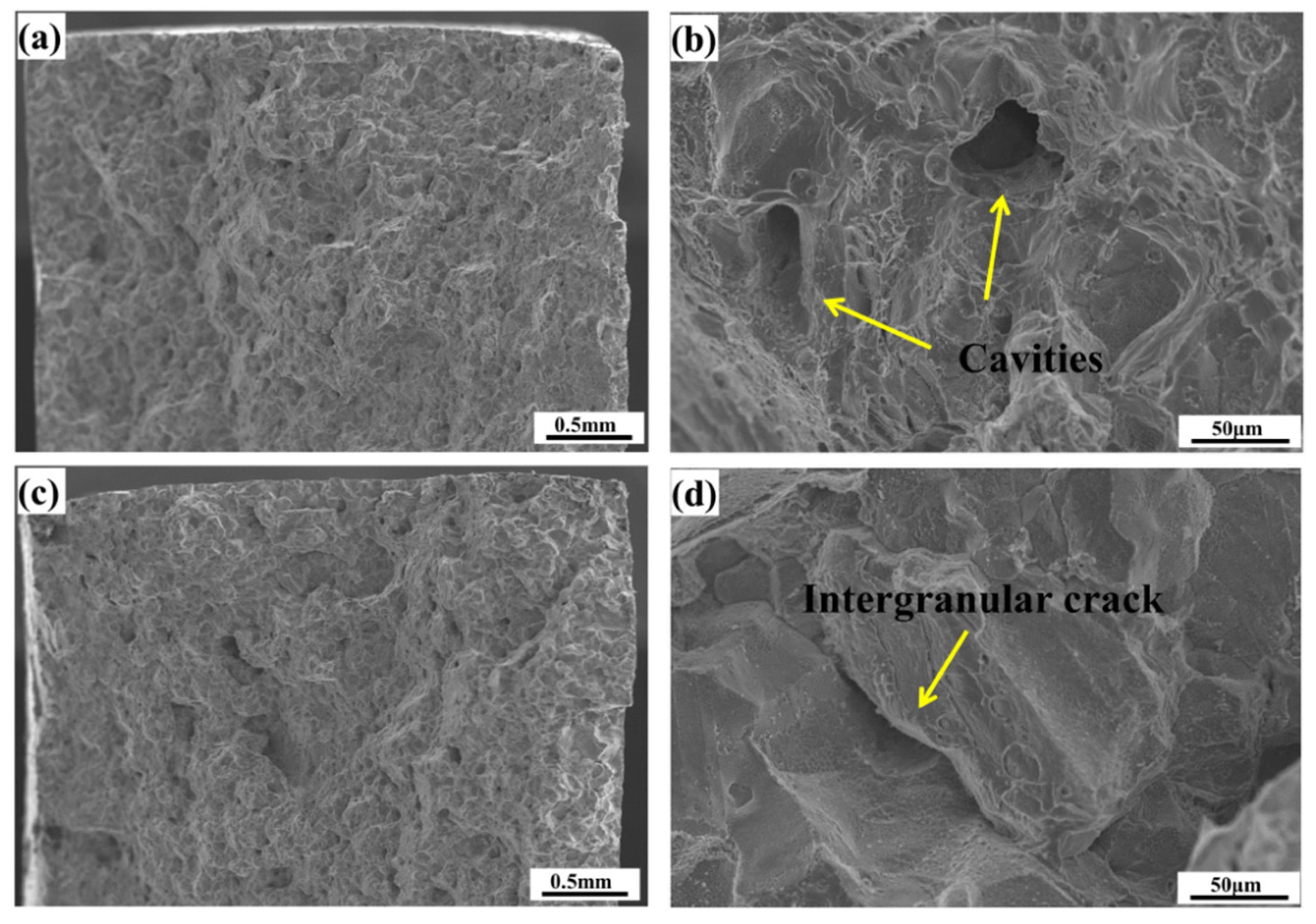
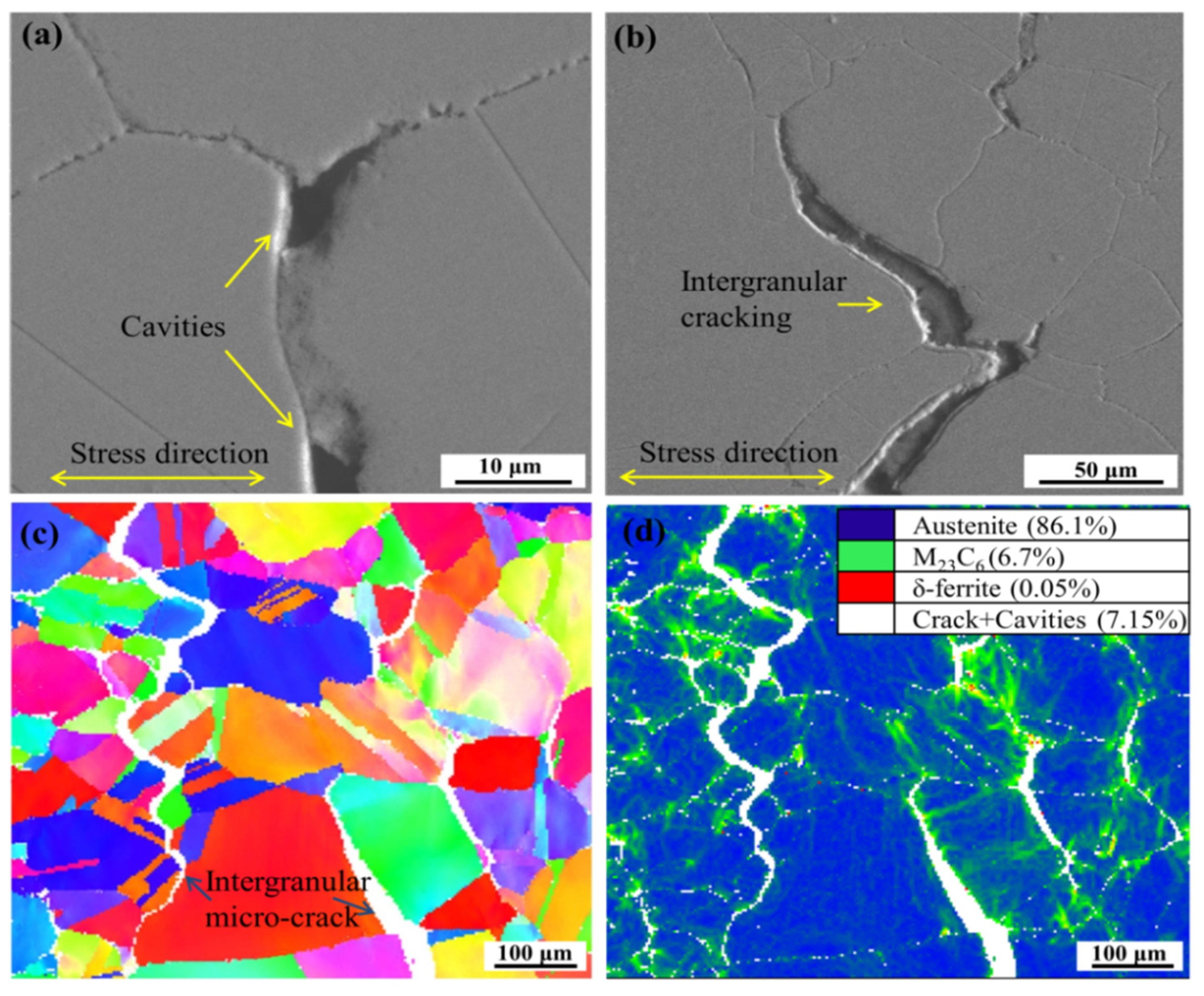
3.2. Cracking and Failure Evolution

In order to better understand crack initiation and propagation in the 310S welded joint, the microstructure near the creep fracture is shown in Figure 7. It can be seen from Figure 7a that some cavities are distributed along the grain boundaries, especially at triple points, where the stress concentration is bound to emerge. As shown in Figure 7c, the cracks are typically intergranular micro-cracks. Moreover, there are abundant brittle phases of M23C6 and δ-ferrite along the grain boundary, as shown in Figure 7d. It should be noted that the existence of M23C6 and δ-ferrite could deteriorate the creep properties of the welded joints. At the same time, the cavities nucleate around the carbides due to the difference in the deformation resistance between the low-stability M23C6 and the matrix. Upon the initiation of the creep process, the cavities are propagated and extended into cracks along the grain boundary, where they separate from discontinuous M23C6. Finally, the intergranular cracks converge, as shown in Figure 7b.

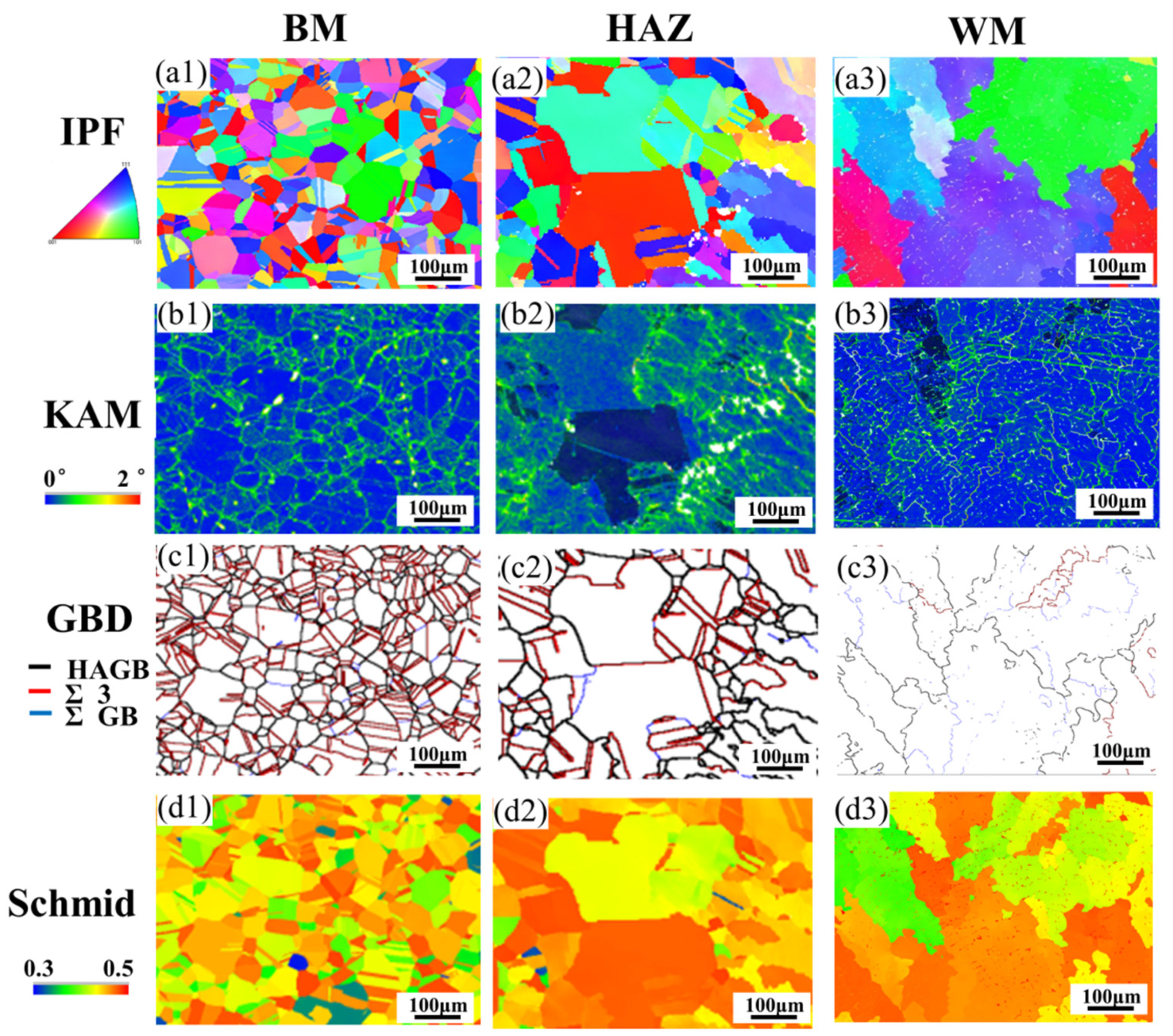
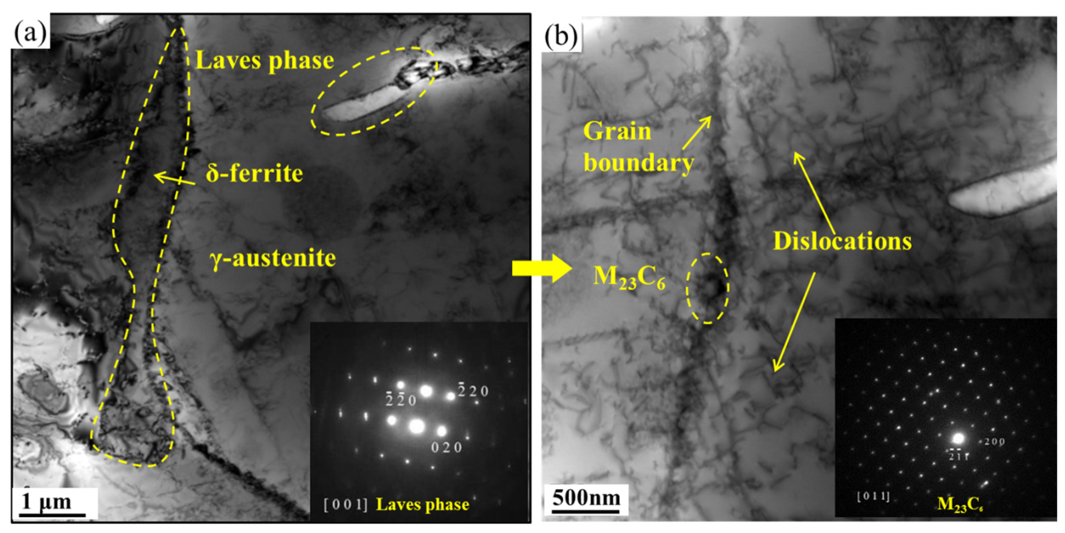
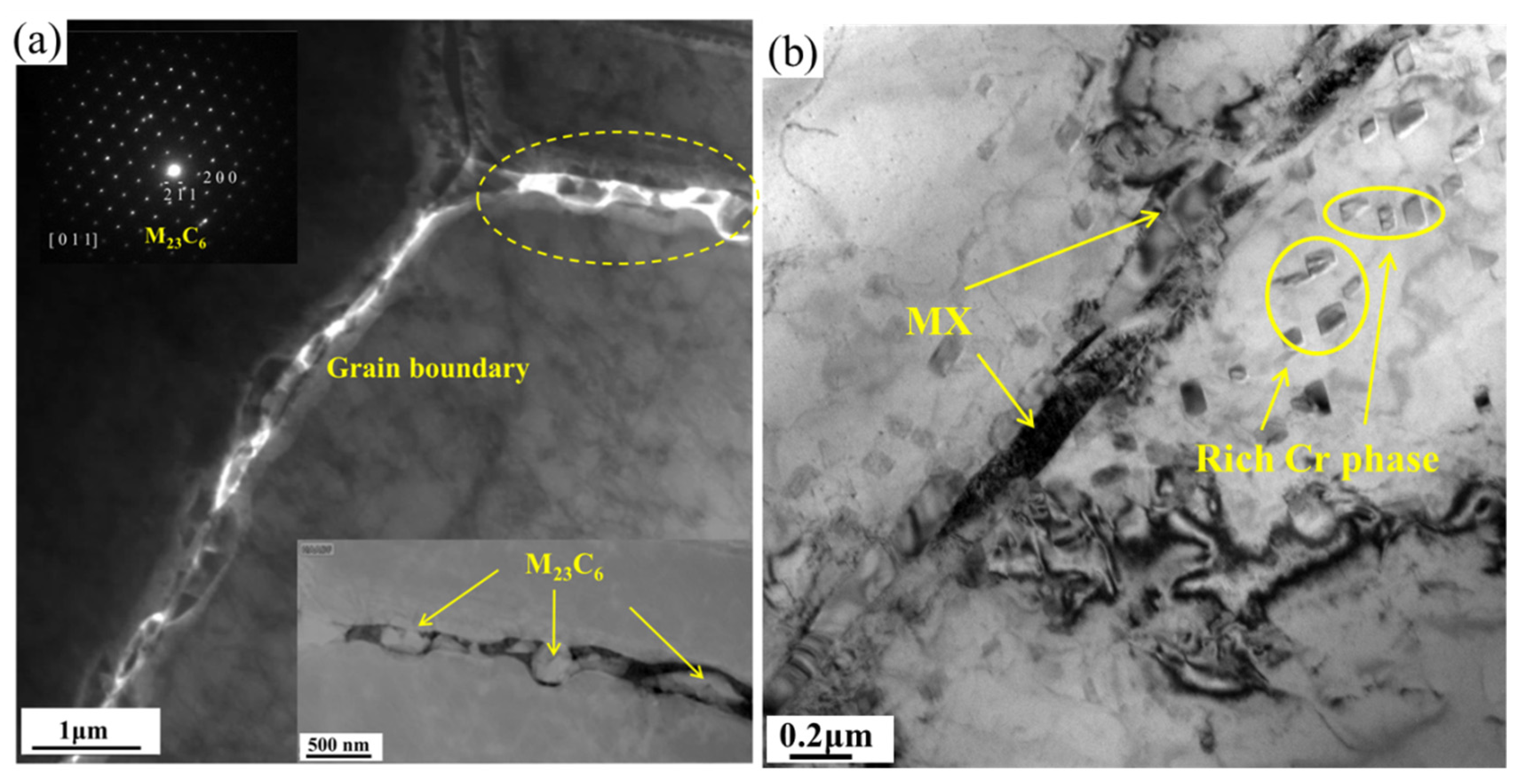
3.3. Microstructure Evolution during Creep Exposure

To visualize and quantify the microstructure evolutions across the welded joints, the EBSD results for the creep specimens are shown in Figure 8. It can be used for evaluating creep damage from the EBSD measurement. The normal directions parallel to the crystal orientations are shown in Figure 8(a1–a3) as the inverse pole figure (IPF) maps. The local misorientation of the welded joint, assessed by kernel average misorientation (KAM), is shown in Figure 8(b1–b3). In the HAZ, higher KAM values (0.80°) indicate a greater crystallographic orientation, resulting in the difference in deformation resistance. As a result, the nucleation of cavities in the HAZ is accelerated. The WM shows the lowest KAM value (0.50°) owing to the reduced precipitate strength effect induced by recrystallization. Wang et al. reported that precipitates contribute to promoting the formation of creep cracks around the grain boundary [31]. Hence, the microstructures of grain boundaries play an important role in inducing creep cracking. Accordingly, the mechanical property is closely related to grain boundary characteristics, as assessed by coincidence site lattice (CSLs) theory, which has been successfully applied in improving materials’ performance [32,33]. The grain boundary distribution (GBD) characteristics, especially twin (sigma 3), are also shown in Figure 4 and Figure 8(c1–c3). Due to the long-term service high stress at elevated temperatures conditions and the varying welding thermal field, the twin boundary distributions in each zone are clearly distinguished. The twin (sigma 3) grain boundaries account for more than half of the content (53.1%) in the BM. The proportion of twin (sigma 3) boundaries in the HAZ is lower (36.8%) than that in the BM. Although the twin grain boundaries represent only 15.8% of the WM, a high alloy element could play the role of alloy strengthening.
Schmid factor maps were used to further analyze the creep deformation behaviors, as shown in Figure 8(d1–d3). The Schmid factor is used to evaluate the slip resistance of multi-crystal materials. As is well known, a lower slip energy is needed to induce a higher Schmid factor [34]. Compared with BM and WM, HAZ presents a higher Schmid factor in welded joints, thus HAZ deformation requires less work. A higher Schmid factor indicates a bigger shear stress between grains in the deformation. The deformations are different in each section of the welded joints, which gives rise to a different Schmid factor in the weld metal, base metal and HAZ. The cracks were usually nucleated in the grain with a high Schmid factor, which demonstrates that the grain is easy to deform. As a result, intergranular cracks tend to appear between grains with high Schmid factors and those with low Schmid factors. Overall, by comparing the key structural characteristics of IPF, KAM, GBD and Schmid factor, the HAZ shows the lowest creep resistance in the welded joint, which is in accordance with the results shown in Figure 4.
In order to clarify the effect of microstructure evolution on the creep failure behavior, TEM was applied to characterize the δ-ferrite and γ-austenite grain boundaries in the WM, HAZ and BM of the specimens. Figure 9 shows that the grain boundary between δ-ferrite and γ-austenite is discontinuous and decorated with Laves phases in the WM. Furthermore, the details of the boundary show that M23C6 carbides are precipitated along the grain boundary and a great many dislocations are also detected near the grain boundary, which would significantly contribute to dislocation strength. As the filler material has a higher Mo content (0.35 wt.%) than BM (0.05 wt.%), such difference may lead to the formation of Laves phases in WM [23]. The composition and SAED pattern in Figure 9a also confirmed it was the Laves phase. This means that the accumulation of the Laves phases in WM plays a significant role in precipitation strengthening during the creep process.
The microstructures were analyzed to clarify the failure location characteristic of HAZ. Figure 10 shows the TEM measurement of the creep sample in the HAZ. It can be seen that more second phases are distributed along the grain boundary of the prior austenite, and especially precipitated in the intersection of the triple grain boundaries. The distribution of elements was also assessed by EDS mapping near the triple grain boundary. As shown in Figure 11, the segregation of Cr, Ni, Ce, Mn and N is visible around the grain boundary. Chemical composition analysis of phases was performed by atom probe tomogram APT. Round rods with a diameter of 500 μm and a length of 15 mm were cut from the HAZ and ground to remove the oxide scale. For the sample subjected to HAZ, the segregation of Cr, C atoms can be clearly observed in the analysis volume from Figure 12. Further, Figure 12 reveals Cr and C-rich cores shells near the grain boundary. The concentration profile indicates peaks of Cr, C concentration, about 64 at.%, 8 at.%, respectively, and poor of Fe, Ni and Si at the core. As expected, brittle phases and element segregations are detected in the triple grain boundary as a result of the high cooling rate in the PAW; however, the formation of these detrimental structures usually leads to crack initiation during the original stage of the creep process. Compared with WM, HAZ enables discrepant deformation in both the heterogeneous coarse grains and the brittle phases, leading to a more regular defect. Besides this, the formation of considerably coarsened M23C6 during long-term creeping is detrimental to the tensile property. Further, with the increase of the in creep time, more cracks accumulate around the brittle phases along the grain boundaries, which eventually lead to creep fracture in the HAZ.
Figure 13 shows representative TEM micrographs of the BM derived from creep samples. It can be observed in Figure 13a that twin microstructures and dislocations are formed around the grain boundaries. On the one hand, low-stacking fault energy metals have great potential to form twin microstructures owing to the deforming and annealing process [35]. As for low-mobility and low-segregation strengthening alloys, the twin microstructure plays a significant role in affecting the serving properties. On the other hand, due to the crystallographic symmetry, coherent twin boundaries have a strong mechanical strengthening effect without deteriorating other properties [35]. As shown in Figure 13b, the interaction of the dislocation and Cr-rich phase is evident. As a result, misfitted dislocations around the precipitates and entangled dislocations are also observed in the BM zone. According to the Orowan passing and cutting theory, the dislocation motion is impeded by the second phases, which in turn strengthens the precipitation [34,36]. Under such conditions, this feature explains the commonly observed Orowan dislocation loop around the second phases, which varies with the content of the second phases. The second phases are not sheared by the dislocation, while the passing mechanism plays a leading role. On the contrary, the cutting mechanism is always dominant if the precipitation is small enough. As shown in Figure 14, the Cr-rich, Ce, and Mn phases are easily observed around the dislocations.
It is worth mentioning that a physics-based constructive model for the strengthening mechanism can be constructed to predict the critical stress (T) during the creep process. As such, the T needs to bend a dislocation between two precipitations (Tp2) or three precipitations (Tp3), which can be shown as follows [37,38]:
T P 2 = 1 + M 1 1 / 2 + M 2 1 / 2 + 1 8 ( M 1 1 / 4 + M 2 1 / 4 ) 4
T P 3 = 1 + ( M 1 1 / 2 + M 2 1 / 2 + M 3 1 / 2 ) + 1 8 ( M 1 1 / 4 + M 2 1 / 4 + M 3 1 / 4 ) 4
M i = K   ( G b 2 / ε l )   N i   ( r i / λ ) 2     ,   i = 1 ,   2 ,   3
where K = 1 + υ / 2 ( 1 υ ) , G is the shear modulus, b is Burger’s vector, ε is the dislocation line tension, N is the dislocation loop, r is the mean area of the Orowan loops, and λ is the space of the particles.
In this study, the threshold value of creep stress at 923 K for the Fe-22Cr-15Ni steel weldment is 115 MPa and 132 MPa, corresponding with the double and triple precipitation models, respectively [38]. The double case model calculates the stresses at about 136 MPa and 164 MPa for the modified 310S austenitic stainless steel welded joint at 600 °C. The back-stress can be evaluated using a hypothetical model for modified 310S stainless steel during the creep process.
As reported by Maruyama et al. [39], precipitated particles with small sizes and dispersive distributions usually play a role in significant precipitation strengthening, which can be employed in the creep failure response. The discontinuously precipitated particles appeared both on grain boundaries and inside grains can obstruct the dislocation, generating a distinct pinning strengthening effect during the initial stage of the creep process. However, when the creep process enters the stable stage, the precipitated particles begin to grow and connect with each other to produce a weakened layer, especially bulky M23C6 particles. As a result, the strengthening effect is reduced, as validated by Maruyama et al. [39]. Moreover, the precipitation of intergranular and M23C6 carbides retarding the occurrence of necking is detrimental to the ductility of the material. According to Tian et al., post-weld heat treatment at 690 °C for 8 h could improve the strength of the welded joint [40]. The ductility reduction during the primary creep was mainly caused by the grain boundary failure and element separation resulting from the carbide precipitation. As the creep proceeded, the M23C6 significantly coarsened along the boundary in the HAZ (Figure 10). According to in situ DIC, the most severe creep deformation occurred in the HAZ. The maximum strain (6.8%) could be as much as three times the average strain in the HAZ. Meanwhile, the hysteresis energy density (HED) in the HAZ could reach 10 times that in the BM [41]. Meanwhile, both intergranular cracks were found on the fracture surface (Figure 5d). According to Jiang et al. [42], cavities nucleate at the unstable incoherent precipitation interfaces and propagate into the micro-cracks near grain boundaries. The creep failure behavior of a welded joint is intergranular cracking, initiated around the coarsened M23C6 carbides at the HAZ boundary and propagating along it [16].
In order to clarify the failure behavior of the welded joints, the creep failure behavior is illustrated in Figure 15. According to the above results, creep failure preferentially occurs in the HAZ. This is because HAZ has a lower resistance to creep deformation as a result of its lower micro-hardness and dislocation density (see Figure 4, Figure 6 and Figure 10). At the same time, the HAZ also experiences high temperatures during the welding process. A high temperature can greatly accelerate second phase precipitation. In this case, creep resistance is obviously reduced, while KAM is increased. The coarsened precipitates, especially those appearing at the triple grain boundary (see Figure 10), tend to block the dislocation movements and decrease the harmonious conditions persisting throughout the high stress and temperature during the creep process. These inharmonious movements also accelerate the nucleation of creep cavities. Interestingly, micro-cavities are usually formed at the intersection of grain boundaries and extend along them. Accordingly, more cavities contribute to an increase in true stress. Considering the sustained endurance of the stress and high temperatures effect during the creep process, these micro-cavities often coalesce with each other to form micro-cracks along the grain boundaries. Eventually, the micro-cracks proliferate along the grain boundaries and generate intergranular cracks, resulting in the creep failure of the welded joints.

4. Conclusions

(1)
The creep failure behavior of modified 310S stainless steel welded joints was analyzed from the microstructure, precipitated phase and dislocation perspectives. Compared with WM, the microstructure of HAZ is highly inhomogeneous, with coarsening grains and lower creep resistances, which result in creep rupture in the HAZ.
(2)
The preferred nucleation around the precipitations and propagation along the grain boundaries of creep cavities lead to intergranular fracture. The higher KAM and Schmid factor and lower GBD are considered the key reasons for the lowest creep resistance being found in the HAZ of the welded joint.
(3)
In the creep servicing, coarsened M23C6, grain heterogeneity and element segregation near the grain boundary often appeared in the HAZ, which is the source of crack initiation and detrimental to tensile strength. As the creep process proceeds, more cracks propagate around the second phase along the grain boundaries, leading to intergranular cracking.

Author Contributions

Conceptualization, Y.J.; data curation, Y.J.; methodology, Y.J.; data analysis, Y.J. and Y.K.; writing–original draft preparation, Y.J.; writing–review and editing, Y.K. and H.C.; supervision, H.C.; final approval, H.C.; project administration, H.C.; funding acquisition, Y.J. and H.C. All authors have read and agreed to the published version of the manuscript.

Funding

This research was funded by LingChuang Research Project of China National Nuclear Corporation.

Data Availability Statement

The data presented in this study are available on request from the corresponding author.

Acknowledgments

The authors would like to acknowledge the financial support provide by LingChuang Research Project of China National Nuclear Corporation. The authors are grateful to the supply of the stainless steel and welded joint samples from Erzhong (Deyang) Heavy Equipment Co., Ltd. and Gang Sha of the Nanjing University of Science and Technology for performing the APT analysis.

Conflicts of Interest

The authors declare no conflict of interest.

References

  1. Liu, Z.; He, Y.; Gao, W. Surface nanocrystallization of 310s stainless steel and its effect on oxidation behavior. J. Mater. Eng. Perform. 1998, 7, 88–92. [Google Scholar] [CrossRef]
  2. Lo, K.H.; Shek, C.H.; Lai, J.K.L. Recent developments in stainless steels. Mater. Sci. Eng. R Rep. 2009, 65, 39–104. [Google Scholar] [CrossRef]
  3. Amirkhiz, B.S.; Xu, S.; Scott, C. Microstructural assessment of 310S stainless steel during creep at 800 °C. Materialia 2019, 6, 100330. [Google Scholar] [CrossRef]
  4. Farooq, M.; Sandström, R.; Lundberg, M. Precipitation during long time ageing in the austenitic stainless steel 310. Mater. High Temp. 2012, 29, 8–16. [Google Scholar] [CrossRef]
  5. Meng, D.; Lu, F.; Cui, H.; Ding, Y.; Tang, X.; Huo, X. Investigation on creep behavior of welded joint of advanced 9% Cr steels. J. Mater. Res. 2014, 30, 197–205. [Google Scholar] [CrossRef]
  6. Lee, E.; Byun, T.; Hunn, J.; Yoo, M.; Farrell, K.; Mansur, L. On the origin of deformation microstructures in austenitic stainless steel: Part I—microstructures. Acta Mater. 2001, 49, 3269–3276. [Google Scholar] [CrossRef]
  7. Sourmail, T. Precipitation in creep resistant austenitic stainless steels. Mater. Sci. Technol. 2001, 17, 1–14. [Google Scholar] [CrossRef]
  8. Zhu, S.; Yang, M.; Song, X.; Tang, S.; Xiang, Z. Characterisation of Laves phase precipitation and its correlation to creep rupture strength of ferritic steels. Mater. Charact. 2014, 98, 60–65. [Google Scholar] [CrossRef]
  9. Gao, Q.; Wang, C.; Qu, F.; Wang, Y.; Qiao, Z. Martensite transformation kinetics in 9Cr–1.7W–0.4Mo–Co ferritic steel. J. Alloys Compd. 2014, 610, 322–330. [Google Scholar] [CrossRef]
  10. West, D.; Hulance, J.; Higginson, R.; Wilcox, G.D. σ-Phase precipitation in 347HFG stainless steel. Mater. Sci. Technol. 2013, 29, 835–842. [Google Scholar] [CrossRef]
  11. Wang, Z.-N.; Liang, T.; Xing, W.-W.; Du, A.-B.; Gao, M.; Ma, Y.-C.; Liu, K. σ-Phase Precipitation Mechanism of 15Cr–15Ni Titanium-Modified Austenitic Stainless Steel During Long-Term Thermal Exposure. Acta Met. Sin. (Engl. Lett.) 2018, 31, 281–289. [Google Scholar] [CrossRef]
  12. Öberg, C.; Zhu, B.; Jonsson, S. Creep behaviour, creep damage and precipitation in the austenitic cast steel HK30 at 750 °C. Mater. Sci. Eng. A 2020, 797, 140253. [Google Scholar] [CrossRef]
  13. Hu, G.; Wang, P.; Li, D.; Li, Y. High-temperature Tensile Behavior in Coarse-grained and Fine-grained Nb-containing 25Cr–20Ni Austenitic Stainless Steel. Acta Met. Sin. (Engl. Lett.) 2020, 33, 1455–1465. [Google Scholar] [CrossRef]
  14. Zhang, W.; Zhang, T.; Wang, X.; Chen, H.; Gong, J. Remaining creep properties and fracture behaviour of P92 steel welded joint under prior low cycle fatigue loading. J. Mater. Res. Technol. 2020, 9, 7887–7899. [Google Scholar] [CrossRef]
  15. Sroka, M.; Zieliński, A.; Golański, G.; Kremzer, M. The Influence of Long-term Ageing on the Microstructure of Sanicro 25 Steel. In Proceedings of the MATEC Web of Conferences, Sibiu, Romania, 5–7 June 2019; Volume 253. [Google Scholar]
  16. Li, Y.; Fan, X.; Cui, H.; Lu, F.; Tang, X. The correlated mechanism of creep fracture and microstructure evolution for precipitated Nimonic 263 superalloy welding joint. Sci. Technol. Weld. Join. 2021, 26, 37–46. [Google Scholar] [CrossRef]
  17. Gonzaga, A.; Barbosa, C.; Tavares, S.; Zeemann, A.; Payão, J. Influence of post welding heat treatments on sensitization of AISI 347 stainless steel welded joints. J. Mater. Res. Technol. 2020, 9, 908–921. [Google Scholar] [CrossRef]
  18. Kaneko, K.; Fukunaga, T.; Yamada, K.; Nakada, N.; Kikuchi, M.; Saghi, Z.; Barnard, J.S.; Midgley, P.A. Formation of M23C6-type precipitates and chromium-depleted zones in austenite stainless steel. Scr. Mater. 2011, 65, 509–512. [Google Scholar] [CrossRef]
  19. Lim, Y.S.; Kim, D.J.; Hwang, S.S.; Kim, H.P.; Kim, S.W. M23C6 precipitation behavior and grain boundary serration in Ni-based Alloy 690. Mater. Charact. 2014, 96, 28–39. [Google Scholar] [CrossRef]
  20. Zheng, L.; Hu, X.; Kang, X.; Li, D. Precipitation of M23C6 and its effect on tensile properties of 0.3C–20Cr–11Mn–1Mo–0.35N steel. Mater. Des. 2015, 78, 42–50. [Google Scholar] [CrossRef]
  21. Sawada, K.; Hara, T.; Tabuchi, M.; Kimura, K.; Kubushiro, K. Microstructure characterization of heat affected zone after welding in Mod.9Cr–1Mo steel. Mater. Charact. 2015, 101, 106–113. [Google Scholar] [CrossRef]
  22. Isik, M.; Kostka, A.; Yardley, V.; Pradeep, K.; Duarte, M.; Choi, P.; Raabe, D.; Eggeler, G. The nucleation of Mo-rich Laves phase particles adjacent to M23C6 micrograin boundary carbides in 12% Cr tempered martensite ferritic steels. Acta Mater. 2015, 90, 94–104. [Google Scholar] [CrossRef]
  23. Isik, M.; Kostka, A.; Eggeler, G. On the nucleation of Laves phase particles during high-temperature exposure and creep of tempered martensite ferritic steels. Acta Mater. 2014, 81, 230–240. [Google Scholar] [CrossRef]
  24. Liu, W.; Liu, X.; Lu, F.; Tang, X.; Cui, H.; Gao, Y. Creep behavior and microstructure evaluation of welded joint in dissimilar modified 9Cr–1Mo steels. Mater. Sci. Eng. A 2015, 644, 337–346. [Google Scholar] [CrossRef]
  25. Kumar, Y.; Venugopal, S.; Sasikala, G.; Parida, P.; Moitra, A. Study of creep crack growth behaviour of a type 316(N) stainless steel weld and its mechanism. Mater. Sci. Eng. A 2018, 731, 551–560. [Google Scholar] [CrossRef]
  26. Jordan, P.; Maharaj, C. Asset management strategy for HAZ cracking caused by sigma-phase and creep embrittlement in 304H stainless steel piping. Eng. Fail. Anal. 2020, 110, 104452. [Google Scholar] [CrossRef]
  27. Wei, Y.; Qiao, S.; Lu, F.; Liu, W. Failure transition mechanism in creep rupture of modified casting 9Cr-1.5Mo-1Co welded joint. Mater. Des. 2016, 97, 268–278. [Google Scholar] [CrossRef]
  28. EN 10095-1999. British Standard; Heat Resisting Steels and Nickel Alloys. British Standards Committee: London, UK, 15 July 1999.
  29. Chabaud-Reytier, M.; Allais, L.; Caes, C.; Dubuisson, P.; Pineau, A. Mechanisms of stress relief cracking in titanium stabilised austenitic stainless steel. J. Nucl. Mater. 2003, 323, 123–137. [Google Scholar] [CrossRef]
  30. Xiao, X.; Li, D.; Li, Y.; Lu, S. Intergranular precipitation behavior and its influence on the stress relaxation cracking susceptibility of Super304H austenitic stainless steel weld metal during long-term aging. Mater. Charact. 2021, 178, 111309. [Google Scholar] [CrossRef]
  31. Wang, Y.; Zhang, W.; Wang, Y.; Lim, Y.C.; Yu, X.; Feng, Z. Experimental evaluation of localized creep deformation in grade 91 steel weldments. Mater. Sci. Eng. A 2020, 799, 140356. [Google Scholar] [CrossRef]
  32. Tan, L.; Allen, T.; Busby, J. Grain boundary engineering for structure materials of nuclear reactors. J. Nucl. Mater. 2013, 441, 661–666. [Google Scholar] [CrossRef] [Green Version]
  33. Hirayama, K.; Yoshii, Y.; Morizono, Y.; Tsurekawa, S.; Hidaka, Y. Grain Boundary Engineering of 10% Cr Ferritic-Martensitic Steel SUH3. ISIJ Int. 2015, 55, 1973–1979. [Google Scholar] [CrossRef] [Green Version]
  34. Li, Y.; Wang, X. Strengthening mechanisms and creep rupture behavior of advanced austenitic heat resistant steel SA-213 S31035 for A-USC power plants. Mater. Sci. Eng. A 2020, 775, 138991. [Google Scholar] [CrossRef]
  35. Lu, L.; Shen, Y.; Chen, X.; Qian, L.; Lu, K. Ultrahigh Strength and High Electrical Conductivity in Copper. Science 2004, 304, 422–426. [Google Scholar] [CrossRef] [PubMed] [Green Version]
  36. Cooper, G.A. Strengthening Methods in Crystals; Kelly, A., Nicholson, R.B., Eds.; Elsevier: Amsterdam, The Netherlands; London, UK; New York, NY, USA, 1971; 627p. [Google Scholar]
  37. Hart, E. Theory of dispersion hardening in metals. Acta Met. 1972, 20, 275–289. [Google Scholar] [CrossRef]
  38. Zhang, Y.; Jing, H.; Xu, L.; Han, Y.; Zhao, L.; Xie, X.; Tang, Z. Fusion boundary evolution, precipitation behaviour, and interaction with dislocations in an Fe–22Cr–15Ni steel weldment during long-term creep. Prog. Nat. Sci. Mater. Int. 2019, 29, 41–49. [Google Scholar] [CrossRef]
  39. Maruyama, K.; Sawada, K.; Koike, J.-I. Strengthening Mechanisms of Creep Resistant Tempered Martensitic Steel. ISIJ Int. 2001, 41, 641–653. [Google Scholar] [CrossRef]
  40. Tian, W.; Wu, D.; Li, Y.; Lu, S. Precipitation Behavior and Mechanical Properties of a 16Cr-25Ni Superaustenitic Stainless Steel Weld Metal During Post-weld Heat Treatment. Acta Met. Sin. (Engl. Lett.) 2021, 1–14. [Google Scholar] [CrossRef]
  41. Fan, M.; Shao, C.; Wang, Y.; Huo, X.; Ma, N.; Lu, F. In-situ DIC investigation on local stress-strain behavior in creep-fatigue test of dissimilar steel welded joint. Int. J. Fatigue 2021, 152, 106464. [Google Scholar] [CrossRef]
  42. Jiang, J.; Zhu, L. Strengthening mechanisms of precipitates in S30432 heat-resistant steel during short-term aging. Mater. Sci. Eng. A 2012, 539, 170–176. [Google Scholar] [CrossRef]
Figure 1. Metallographic morphology of 310S stainless steel welded joints (a) WM (b) HAZ and (c) BM.
Metals 12 00116 g001
Figure 2. The stress–displacement curve of the welded joints.
Metals 12 00116 g002
Figure 3. Creep rupture of the welded joints at 600 °C including 9Cr welded joint [27], S309 base metal [28] and S310 base metal [28].
Metals 12 00116 g003
Figure 4. Fracture morphology of the creep rupture specimens at 600 °C under 238 MPa stress for 430 h: (a,b) macroscopic morphology of the creep fracture; (c) amplified fracture of HAZ.
Metals 12 00116 g004
Figure 5. Fracture morphology of the creep rupture specimens: (a) macroscopic morphology under 238 MPa, (b) the amplified fracture surfaces of (a), (c) the macroscopic morphology under 170 MPa, (d) the amplified fracture surfaces of (c).
Metals 12 00116 g005
Figure 6. Micro-hardness distribution of the as received welded joint.
Metals 12 00116 g006
Figure 7. Microstructure near creep rupture: (a) cavities; (b) intergranular cracking; (c) EBSD analysis of intergranular crack; (d) phase distribution of (c).
Metals 12 00116 g007
Figure 8. EBSD analysis of BM, WM and HAZ for the creep specimen marked in Figure 4a: (a1a3) inverse pole figure (IPF); (b1b3) kernel average misorientation (KAM); (c1c3) grain boundary distribution (GBD); and (d1d3) Schmid factor.
Metals 12 00116 g008
Figure 9. TEM characterization of the creep sample in WM: (a) δ/γ boundary (b) detailed boundary.
Metals 12 00116 g009
Figure 10. TEM characterization of the creep sample in HAZ (a) triple grain boundary (b) twin grain boundary.
Metals 12 00116 g010
Figure 11. EDS of grain boundary of the creep sample in HAZ.
Metals 12 00116 g011
Figure 12. Atomic probe maps and concentration profile of the sample subjected to HAZ.
Metals 12 00116 g012
Figure 13. TEM observation of the creep sample in BM: (a) twin grain; (b) dislocation.
Metals 12 00116 g013
Figure 14. EDS of the grain boundary of the creep sample in BM.
Metals 12 00116 g014
Figure 15. Schematic of the creep rupture behavior: (a,d) micro-cavities nucleation around the triple grain boundary and precipitates; (b,e) micro-cavities growth and coalescence; (c,f) micro-cavities form cracks.
Metals 12 00116 g015
Table 1. The main chemical compositions of BM and filler materials (wt.%).
ElementsCCrNiMnMoSiCoVNbCeTaFe
BM0.1020.511.12.00.052.200.100.080.030.04/Bal.
Filler materials0.0926.421.82.00.350.380.200.080.05/0.20Bal.
Publisher’s Note: MDPI stays neutral with regard to jurisdictional claims in published maps and institutional affiliations.

