Article

Study on Medium-Thick Al-Alloy T-Joints by Dual P-GMAW Bilateral Synchronous Welding

1
School of Materials Science and Engineering, Jilin University, Changchun 130022, China
2
Engineering Technology Centre, CRRC Changchun Railway Vehicles Co., Ltd., Changchun 130062, China
3
Faculty of Materials and Manufacturing, Beijing University of Technology, Beijing 100124, China
4
Jiangsu Automation Research Institute, China Shipbuilding Industry, Lianyungang 222006, China
*
Author to whom correspondence should be addressed.
Metals 2021, 11(11), 1794; https://doi.org/10.3390/met11111794
Submission received: 7 October 2021 / Revised: 3 November 2021 / Accepted: 6 November 2021 / Published: 8 November 2021
(This article belongs to the Special Issue Welding and Fatigue of Railway Metallic Materials)

Abstract

:
The T-joints of medium-thick 6082 Al-alloy plates created by dual pulsed gas metal arc welding (P-GMAW) and bilateral synchronous welding were investigated to improve weld quality using the adaptive deposition method, which calculates the minimum amount of deposition according to the welding condition, groove size, and cross-sectional area, effectively reducing the heat input and deformation of the welds on the basis of weld filling. The optimized linear energy with a wire feed speed (WFS) of 9.5 m/min can ensure a well-formed weld with a complete root fusion, and high-quality T-joint welds were obtained both in root openings of 0 mm and 1 mm. The biggest penetration was 4 mm, which was four times more than that of the result from a single torch welding process. When the distance between the two welding torches exceeded 20 mm, the molten pool was completely separated, and process pores were observed in the unfused root zone. Influenced by the thermal cycles in asymmetric welding, the hardness distribution changed: the width of the softer zone at the base plate with the fore arc was smaller than that zone with the rear arc. Furthermore, dual P-GMAW bilateral synchronous welding with an asymmetric heat source can further reduce the deformation of the welded joint by about 20% compared to that of symmetric welding.

1. Introduction

Owing to its excellent performances such as high specific strength, great stress corrosion resistance, good weldability and formability, Al-alloy and other advanced materials have become the preferred alloys for automobiles and rail transit [1,2,3,4]. T-joints are an exciting topic for automobile and aerospace manufacturers [5,6], and T-joint welding of medium-thick Al-alloy plates usually require three processes: root, filling, and cover welding [6,7]. However, multi-pass welding would result in defects such as poor fusion quality and low welding efficiency, and these greatly reduce the manufacturing reliability of the components [8]. The dual heat source bilateral synchronous welding technology aimed to improve the welding efficiently and has been successfully applied to mass production for producing lightweight equipment in an energy conservation and emission reduction manner.
T-joints of aluminum alloy fabricated by dual laser bilateral synchronous welding have been extensively studied [9,10,11,12]. It can reliably achieve high-quality symmetrical welding compared with traditional welding processes [13,14]. Narrow and deep welds were usually obtained by laser and electron beam welding. However, the scope of application is greatly limited due to the high cost and the difficulty in being applied in large structures. Due to the comparatively easier applicability and lower cost, gas metal arc welding (GMAW) was normally selected as the preferred welding process for thick Al alloy plates. The process of conventional welding technology for a medium-thick plate is composed of preheating, one-sided GMAW, back chipping via carbon arc air gouging, polishing, magnetic particle examination, repeated preheating, GMAW on the other side, and post-heating [15,16,17]. Furthermore, large welding deformation will be deduced and is difficult to be corrected, causing increasing complication and decreasing the productivity further [18]. The energy density of the laser is high, and the welding pool is relatively small, so the biggest difference in residual stress between laser welding and arc welding is that the residual stress in laser welding is much smaller and the welded parts are not easily deformed. However, compared to laser welding, arc welding is easy and convenient to operate, the equipment is quite cheap, and it is more widely used. Recently, double-sided synchronous GMA welding has been paid more and more attention due to its advantages such as increased welding depth with a lower heat input, improved welding efficiency, and reduced deformation [9,19,20,21,22].
Compared with other welding methods and processes, double-sided arc welding is suitable for T-joint structure because of the advantages such as higher efficiency, larger penetration depth, and smaller deformation. The double-sided arc welding process has been adopted to join light metal alloy with improved welding quality in comparison with conventional processes, as reported by Shen et al. [5]. Conventional processes in this part are the multi-pass welding, and the double side welding is used to improve the weld efficiency while ensuring that the joint does not have misalignment and complete penetration [8]. The three steps of root, filling, and cover welding for the T-joint welding of 15 mm, 20 mm, and 30 mm 6082-T6 Al-alloy plates with the improved welding efficiency to some extent was reported [22,23], but the process complexity increased. The multi-layer and multi-pass welding method was mostly adopted in the conventional T-joint welding process of medium-thick Al-alloy plates. Although high-quality welds can be obtained by the above method, there are problems: the melted metal only fills the groove, the fusion is poor or not fused, and deformation of the welded plates is severe due to heat input during the multi-layer and multi-pass welding process. Thus, there is an urgent need for a new welding process suitable for robot and automatic welding, which can improve the welding efficiency on the premise of ensuring the weld quality and root fusion.
There are many T-joints that need to be welded in railway vehicles and components, and it is necessary to clean the root during multi-pass welding to avoid the problem in which the root of the T-joint cannot be welded during the traditional welding process of a 15 mm thick Al plate, resulting in a lower welding efficiency and poor welding quality [17,18]. To improve the quality and efficiency of medium-thick plate welding, the welded T-joints for medium-thick Al-alloy plates by dual P-GMAW bilateral synchronous welding using adaptive deposition method were investigated. Firstly, the effect of parameters such as root opening, wire feed speed (WFS), travel speed, and linear energy on weld formation during a single P-GMAW process was studied. The optimized welding parameters are used in dual P-GMAW bilateral synchronous welding processes, and the effect of distance between the torches during bilateral synchronous welding was discussed. The deformations of welds were measured, and the effect of heat input and two arcs were discussed. It is expected to realize the single-pass weld formation of T-joints for 15 mm Al-alloy plates, and the results and conclusion are on the basis of the technological and theoretical foundation for T-joint welding of a medium-thick plate.

2. Materials and Methods

2.1. Materials

In this study, the 6082-T6 aluminum alloy with a dimension of 400 mm × 180 mm × 15 mm was selected as the base material (work-pieces). ER5087 with a diameter of 1.6 mm was used as the filler wire. Details of the chemical composition of selected materials are shown in Table 1. Before fillet welding, steps such as acid etching by acetone and oxide removal were carried out to eliminate the influence on the results.

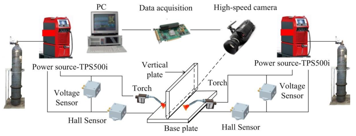
2.2. Experimental Setup

To improve the quality and efficiency of medium-thick plate welding, the welded T-joints for medium-thick 6082-T6 Al-alloy plates fabricated by dual P-GMAW bilateral synchronous welding using the adaptive deposition method were investigated. The fillet weld with a 55-degree groove was applied using filler wire ER5087. Firstly, fillet welding by a single P-GMAW process was carried out to analyze the effect of parameters such as root opening, wire feed speed (WFS), travel speed, and linear energy on the droplet transfer and weld formation to ensure the interval of optimal welding process parameters, and the results were verified by dual P-GMAW bilateral synchronous welding. Dual P-GMAW bilateral synchronous welding was divided into two ways: symmetric and asymmetric. The deformations of welds were measured, and the effects of two arc and metal flow were discussed. It is expected to realize the single-pass weld formation of T-joints for 15 mm Al-alloy plates, and the results and conclusion are on the basis of the technological and theoretical foundation for single-pass welding by dual P-GMAW bilateral synchronous welding using the adaptive deposition method.
The dual GMAW bilateral synchronous welding system is shown in Figure 1, with two torches mounted on two six-axis industrial robots (Kuka, KR 16 R1610, Shanghai, China) that are fixed on both sides of the T-joint, respectively. The control systems of two robots are connected through external I/O to control the synchronous movement on both sides. Simultaneously, the synchronous arcs of two welding sources were realized by a Beafu module. The voltage and current signals were collected by sensors in real time, and the arc shape and molten pool behavior during welding were captured by a high-speed camera (HSVC) (MEMRECAM HX-3e High Speed Camera Systems, NAC Image Technology, Tokyo, Japan). The signal sampling rates and image capture rate are 10 kHz and 2000 s−1, respectively, to investigate the instantaneous change of arc characteristics and molten pool behavior.

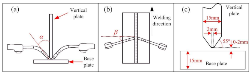
2.3. Experimental Parameters

The welding travel angle and operating angle have a significant influence on the droplet transfer and metal flow during fillet welding [6,24,25]. To ensure the welding results, the operating angle is set as α equal to 55°, which is the angle of the groove of the vertical plate, as shown in Figure 2a–c. According to British Standard: BS EN 15085-3:2007, named railway applications—welding of railway vehicles and components—Part 3: Design requirements, the groove of the vertical plate during a double fillet weld for thick plate welding should be between 50 degrees and 60 degrees, and the angle of 55 degrees is relatively reasonable on the basis of data accumulation of mass production practice. The welding travel angle is defined as the angle between the welding direction and normal plane of weld seam, as shown in Figure 2b, which is an important parameter in the double fillet welding process, and a larger welding travel angle will cause an unstable arc and molten pool due to the increased equivalent length of the arc; a smaller welding travel angle will cause the liquid metal flow to the lower side of weld pool due to the effect of arc pressure and gravity. A large number of experiments prove the well-formed weld when pushing the metal by arc during the welding process. A smaller arc pressure results in a bigger welding travel angle and will affect the depth of the molten pool, which also affects the heat input during the welding process. Taken together, the welding travel angle was set as β equal to 15°. Heat input is a direction factor that affects the quality of the weld formation, as calculated by the root face, groove angle, and gap between the work-pieces (Figure 2c).
In this paper, dual P-GMAW bilateral synchronous welding consists of symmetrical and asymmetrical welding. Figure 2 shows the schematic diagram of symmetrical welding, which means that the distance between the two torches along the welding direction is 0 mm (welding heat sources are positioned on the same cross line), as shown in Figure 2b. Figure 3b shows the asymmetrical welding; asymmetrical welding means that the distance between the two torches is beyond 0 mm. In the present paper, 10 mm, 15 mm, and 20 mm are selected, as shown in Figure 3b. To ensure the experiment results, the other parameters need to be consistent; the operating angle α was set as equal to 55°, and the welding travel angle was set as β equal to 15°.
Adaptive deposition was proposed to determine the heat input based on the weld size, groove, and section area of the base metal to be welded. Adaptive deposition is a method that requires minimum power to ensure groove filling, which can effectively reduce the heat input and reduce the deformation of the weld. The groove that needs to be filled is shown in Figure 4a, and the corresponding areas are shown in Figure 4b. According to adaptive deposition, the following equation can be drawn:
V   =   V 1 S   ×   W F S   ×   t   =   S 1   +   S 2   ×   T v   ×   t
where V is the volume of filler wire at welding time t; V1 is the volume to be welded at welding time t; WFS is the wire feed speed; Tv is the welding speed; S is the cross-section area of wire; S1 and S2 are the area that are shown in Figure 4. The welding parameters based on Equation (1) are shown in Table 2, the welding processes for different WFS are divided into five groups, and root openings are divided into four groups; the corresponding travel speeds (TSs) are listed in Table 3.
Linear energy is an important parameter evaluating the heat input. The influence of welding process parameters, welding current, arc voltage, and welding speed on the welding thermal cycle was considered by linear energy, the width of the heat-affected zone increased with increasing linear energy, the area heated to high temperature widens, the residence time at high temperature increased, and the cooling rate slowed down. As the linear energy increased, both the temperature and fluidity of the molten pool toward the weld root increased, while the viscosity of the liquid metal decreased. The relationship of linear energy can be expressed as follows:
p   =   U ¯ I ¯ v η
where U ¯ is the average voltage, I ¯ is the average current, v is the travel speed, η is the welding process efficiency—the ratio of the power really used to heat the welded part to the total power, which is selected as 85% in the present paper.
To study the effect of the welding procedure on the microstructure and mechanical properties of T-joints, an optical microscope (OM, Olympus LEXT OLS4100, Toyko, Japan) is used to capture pictures of the cross-section of T-joints. A polarizing microscope (Guangzhou Weiyi Metallographic Test Instrument Co.; LTD, WY-20BD, Guangzhou, China) is carried out to further study the microstructure, and the weld sample is electro-polished by Keller’s reagent (2.5 mL HNO3, 1.5 mL HCL, 1mL HF, 95 mL H2O) (Jiang Yun, Kunming, China). Micro-hardness is used to evaluate the mechanical properties. The micro-hardness is measured with Vicker’s method using a Vicker hardness tester (SCTMC DHV-1000 Hz, Hangzhou Quantum Testing Instrument Co.; Ltd.; Shanghai, China) with a 200 g (0.2 HV, 1.96 N) load for 15 s. The welding thermal cycles during symmetric welding and asymmetric welding (the distance between the two torches was 15 mm) was measured, ten channels were used each time, and the sampling rate of each channel was 10 S/s.

3. Results and Discussion

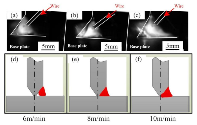
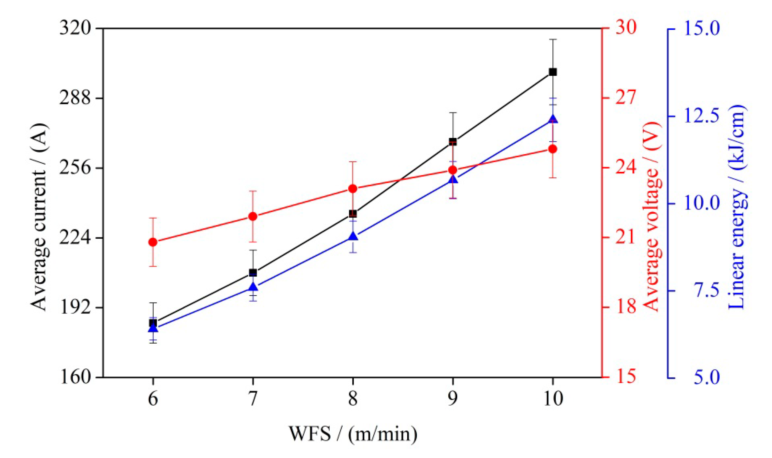
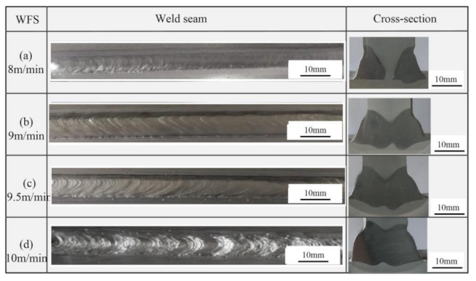
3.1. Effect of Heat Input

Figure 5 shows the comparison of characteristics of droplet transfer and molten pool with different heat inputs. In the GMAW process, the droplet was transferred into the molten pool under the action of surface tension, electromagnetic force, and arc pressure. The linear energy was low at a WFS of 6 m/min, and the arc pressure pushing the melted metal to the root of groove was lower, resulting in poor fluidity of molten pool, as shown in Figure 5a. The smaller heat input resulted in poor melt between the filler metal and the base metal, as shown in Figure 5d. The droplet transfer frequency at a WFS of 8 m/min increased by 26% in comparison with that of 6 m/min. The increased WFS also enhanced the heat input and arc pressure as well as the fluidity of molten pool metal toward the weld root, the melted metal could fulfill the groove, as shown in Figure 5b–e. With further increasing the heat input, the heat input to the base metal enhanced, and the melted metal pushed by arc pressure was also enhanced. When WFS increased to 10 m/min, the average current during this process was about 300A, and the droplet transfer frequency increased by 39% in comparison with that of 6 m/min. The droplet transfer mode at this time was transformed from globular transfer to spray transfer. The wettability between the filler metal and the base metal was further improved due to the larger heat input and higher speed of the droplet, as shown in Figure 5c–f.
The relationship among the welding current, arc voltage, and linear energy is shown in Figure 6; the error bars show the standard deviation. Linear energy is in direct proportion to WFS. Figure 7 shows the welded joints of single-side welding by a single heat source in which the WFS increases from 6 to 10 m/min. The measured and calculated data used to prove the stable welding process and the calculated linear energy can be used by quantitative analysis of the welding processes. The weld zone and heat-affected zone can be clearly observed by corroding of Keller’s reagent. When the WFS is less than 8 m/min, the linear energy is small (less than 11.7 kJ/cm), and the wetting phenomena between the filler metal and the base metal is poor. When the WFS is greater than 9 m/min, the base metal melts well with the filler metal, as shown in Figure 7d–e.
Figure 8 shows the T-joints of medium-thick Al-alloy plates fabricated by dual P-GMAW bilateral synchronous welding using the adaptive deposition method. During the welding process, the root opening is 0 mm, with WFS increasing from 8 to 10 m/min. By comparing the weld formation and root fusion quality under different WFS, it can be concluded that the smaller heat input leads to an incomplete fusion at the WFS of 8 m/min. The groove of the T-joint was completely melted with WFS increasing from 9 to 9.5 m/min. However, with continuous accumulation of heat and the thermal strengthening effect of the opposite molten pool on the base metal, surface defects such as burning damage and discontinuity easily appear on the weld. Especially when the WFS increases to 10 m/min, the linear energy reaches 12.4 kJ/cm, and the weld surface burns seriously, as shown in Figure 8d.

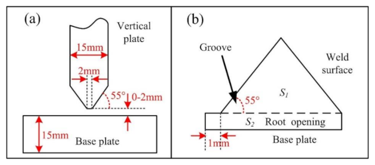
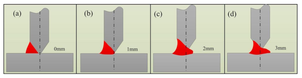
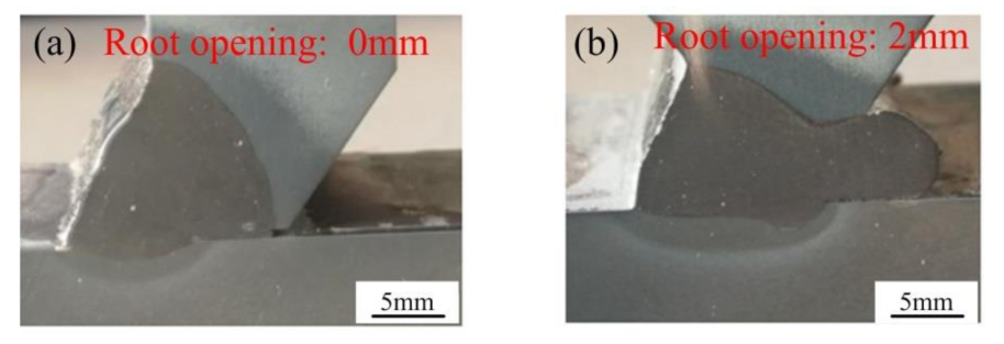
3.2. Effect of Root Opening between Work-Pieces

In the T-joint welding process, a root opening reserved between the vertical plate and the base plate can make the welding arc close to the root of the weld, resulting in a better fusion with the base metal. In addition, the increase in reserved root opening will increase the area of the weld cross-section according to the welding method of adaptive deposition, which can increase the amount of filler metal and change the fluidity of the molten pool to the opposite side, thus improving the formation quality of the weld. However, if the reserved root opening is too large, the liquid molten metal will flow downward under the effect of gravity, resulting in a serious bulge on the weld surface near the base plate and other defects near the vertical plate. The reserved root opening between the work-pieces plate of the T-joint was set as 0 mm to 3 mm, respectively, and the WFS was set as 9 m/min to analyze the influence of different gap on the weld quality of the T-joint.
The filling area is determined by the shape of the weld groove and the root opening. When the shape of the weld groove is certain, the filling area is proportional to the root opening. When the root opening was 0 mm, the section of the weld to be welded was 7.5 mm2 smaller than the root opening, and the travel speed was larger at the same WFS, resulting in a smaller linear energy. The heating ability of the arc to groove root was limited due to the limited arc energy. The droplets were more difficult to be transmitted to the root by the smaller arc pressure at the same time. As a result, the welded groove was filled but not infiltrated, as shown in Figure 9a. When the root opening increased to 1 mm, the cross-section of the groove to be welded increased, and the travel speed decreased. The enhanced linear energy melted the base metal (work-pieces), forming a weld with the filler metal, as shown in Figure 9b. When the root opening was greater than 2 mm, the tip of the vertical plate (blunt edge) was easy to be burned under the greater linear energy, causing liquid metal to flow to the opposite side under the push of arc pressure, as shown in Figure 9c–d. In T-joint welding, it was difficult to form the weld under the unstable weld pool caused by the mutual influence of arc and the liquid metal on both sides.
Figure 10 shows the welded joints at different root openings using a single welding source at WFS of 9 m/min. When the root opening was 0 mm, the weld was well-formed, the welded joint was of good quality, the vertical plate was melted well, and the fusion between the filler metal and base metal was complete. However, the fusion between the filler metal and base plate was incomplete: the depth of weld pool at the surface of the weld on the base plate was about 2 mm, while there was no wetting at the root of the groove on the base plate, as shown in Figure 10a. When the root opening was 2 mm, as shown in Figure 10b, the root of the vertical plate was melted due to the high linear energy. The molten pool/liquid metal were pushed to the opposite side of the groove. If a root opening of 2 mm is used for dual P-GMAW bilateral synchronous welding, the molten pool on the opposite side would affect the liquid metal flow, resulting in an unstable droplet transfer and unstable welding process.

3.3. Effect of Distance between the Two Torches on Both Sides

To ensure the experiment results, the other parameters need to be consistent: the root opening was 1 mm, the WFS was 9.5 m/min, and the results are shown in Figure 11. In T-joints for medium-thick Al-alloy plates by dual P-GMAW bilateral synchronous welding, when the root opening was 0 mm and there was symmetric welding from two torches, the vertical plate was heated by two arcs on both sides. The molten pool on both sides of the groove also can heat the opposite side. Under the synergistic influence of both, the T-joint was well formed with high quality, and the welded joint achieved full penetration from the observation of the cross-section, as shown in Figure 11a. As for the distance of 10 mm shown in Figure 11b, an undercut in the T-joints appeared at the vertical plate on the side with the rear arc due to the softened or melted vertical plate by the fore arc. The leading side of the rear arc overlapped to the solidifying side of the fore arc when the distance of the two torches was 10 mm. The base metal of the rear arc was melted by the fore arc, resulting in the liquid metal being pushed to the opposite side of rear arc by arc pressure, as shown in Figure 11b.
When the distance between the two torches was 15 mm, the undercut disappeared, indicating that the molten pool of the fore arc was less than 15 mm. The fusion of the vertical plate of both arcs was the same, while the depth of fusion in the base plate between the two arcs was different, and the depth of the rear arc was larger than that of the fore arc due to the heat of the fore arc, as shown in Figure 11c. The solidifying side of the weld pool of the fore arc exceeded the leading side of the rear arc at a distance of 20 mm (Figure 11d); this meant that no junction point was observed between the two weld pools. The heat effect of the fore arc to the rear arc zone was not significant, and the weld formation was similar to that of the single heat source, which lost the significance of dual P-GMAW bilateral synchronous welding, as shown in Figure 11d. Figure 11d shows an asymmetric weld with different penetration on both sides of weld; the right side of Figure 11d shows the fore arc, and the left side shows the rear arc. The fore arc has a heating effect on the base metal for the left side, which is at a high temperature after fore-arc welding, resulting a deeper penetration of the left side with the same heat input in comparison with the right side. This phenomenon can be explained by the existence of the colder zone in front of the electric arc comparing to the rear of the electric arc, as well as due to the accumulation of thermal effects in the rear of the electric arc. The depth of fusion of the rear arc was larger than that of the fore arc. From the above, when the root opening was set to 0 mm or 15 mm, the molten pool on both sides could connect to each other without interference, and the weld formation was of high quality.

3.4. Microstructure in the Welded Joint

Figure 12 shows the macrostructure and microstructure morphology of the T-joint weld with an unfused root, the WFS is 9.5 m/min, and the distance between the two torches is 20 mm. When the distance between welding guns increases in dual P-GMAW bilateral synchronous welding, the molten pool is elongated and the energy is gradually dispersed, leading to an increase in the proportion of unfused length. When the distance between the two welding torches exceeds 20 mm, the molten pool is completely separated, as shown in Figure 11d and Figure 12a. For thick plate welding, the increase in energy loss rate and the decrease in the overall heat input will hinder the escape of pores, resulting in an increase in porosity. The pores in Al-welds are mainly divided into two types: hydrogen pores and process pores. As for hydrogen pores, metal hydrides are formed on the interface between the gas and metal during the welding process, and it can be observed on the wall surface. Process pores are mainly caused from their inability to escape during the solidification of the molten pool. The pores that appear in Figure 12 are process pores, as shown in Figure 12d. Extruded grains were observed in the base plate, and the direction was consistent with the rolling direction, as shown in Figure 12c. The heat-affected zone and weld zone showed a typical solidification microstructure.
Figure 13 shows the macroscopic and microscopic morphology of a T-joint weld with full penetration, the WFS is 9.5 m/min, and the distance between the two torches is 15 mm. The solidification of the weld generally begins from the boundary of the weld pool, and it solidifies from the solid–liquid interface. Solidification is divided into three ways: plane solidification, cell solidification, and dendritic solidification. The way of solidification depends on the temperature gradient, crystallization rate, and the supercooling of components [23,24,25]. As for T-joints in this paper, when crystallization from the boundary of the molten pool began, the microstructures were super-cooled to form cell crystals; these grains adhered to the unmelted base material and they started to grow, as shown in Figure 13c,e,f. The grains grew along the direction of the temperature gradient and the size was about 150 um, these zones were named the fusion zone (FZ), and the details are shown in Figure 13d. At the center of the weld, the degree of the supercooling continued to increase, and the liquid metal received little restraining force around the core and can be nucleated from the inside of the liquid phase during crystallization. In this situation, equiaxed grains were formed, and the size was about 80 um, as shown in Figure 13b. During the welding process, the melting of the filler metal filled to the weld zone and recrystallization occurred in the base material during the action of thermal cycling (heat-affected zone: HAZ); both of these will affect the weld strength.

3.5. Hardness Distribution

The hardness distribution of the welded joint is one of the important parameters to evaluate the welding quality [26]. The welding procedures and the distance between the torches may weaken the weld properties. Figure 14a,b respectively are the hardness distribution of the welded joint of symmetric welding and asymmetric welding. The welded joints are shown in Figure 11a,c. The minimum hardness in both welded joints was distributed in the heat-affected zone (HAZ) in the base plate, the value was about 65 HV. The maximum hardness appeared in the base metal; it was about 120 HV. The hardness in the weld zone (WZ) and HAZ in the vertical plate are about 80 HV and 90 HV. Although the trend of hardness distribution was consistent in both welded joints, the local characteristics are different.
The hardness distribution on both sides of the welded joint in symmetric welding was almost the same due to the symmetric thermal cycles. Influenced by the different cooling conditions, the hardness of the HAZ in the base plate was lower than that of that in the vertical plate. The cooling conditions of the base plate were heat convection to air and heat conduction to the surrounding area and the work bench, while the cooling conditions of the vertical plate were heat conduction to the base plate and heat convection to air, leading to asymmetric thermal cycles. For the free-growth model, the grain size is inversely proportional to the undercooling ΔT; that is, grain growth depends only on undercooling (initial temperature) in this case [26]. The equiaxed grains appeared in the HAZ and the zone nearby the HAZ in the vertical plate, while the columnar grains appeared in the corresponding zones in the base plate, as shown in Figure 12 and Figure 13. The grain size of the weld is inversely proportional to the cooling rate of the molten pool in welding heat treatment based on the same welding conditions. The smaller grains can enhance the dislocation among the grains, resulting in better strength and toughness. That is, materials with larger grain size have poor mechanical properties [27,28]. It agrees with the result obtained in this section. In the welded joint of asymmetric welding, the hardness distribution was the same as that in symmetric welding. However, the widths of the HAZ in the base plate were different, the width at the side of the fore arc was larger than that of the opposite side. It was because having been affected by the fore arc, the molten pool temperature of the rear arc was higher, and the smaller grain size contributed the larger hardness due to the larger undercooling.

3.6. Welded Joint Deformation

The heat input is large for T-joint dual P-GMAW bilateral synchronous welding of medium-thick Al-alloy plates, and the temperature of the base metal increased sharply. During the welding thermal cycle, welding distortion easily appeared on the base plate, as shown in Figure 15, where the black line is the original size of the base plate, and the yellow line is the size after deformation; Figure 15b shows the weld structure. The welded plates will be fixed on the welding bench, but the welding distortion caused by the heat input should not be overlooked. The length from the torch to the base plate usually is consistent during the robotic automatic welding, and the distance from the torch to the base plate will be shortened when welding distortion occurred during the welding process, which will cause the burning of the conductive nozzle and the interruption of the welding process. In general, the maximum deformation of the welded plate will occur at the center of the base plate boundary, and the values shown in Figure 16 represent the maximum deformation over several measurements.
To prevent serious deformation of the work-piece and improve the stability of the welding process, the base plate was fixed on the workbench, and the work-pieces were fixed by spot welding. The T-joint being in a weak constrained state would not move in welding directions during the welding process due to the large gravity of the base metal and the small arc pressure. The root opening during this section was set to 1 mm, the root opening would become 0 mm during the welding process. The linear energy was calculated based on the root opening 1 mm using an adaptive deposition method; if the root opening reduced to 0 mm, the area to be filled decreased, while there was no change in linear energy. Therefore, the heat input at this condition was also larger, so that the welding distortion occurred on the welded plates, as shown in Figure 16. The welding thermal cycles during symmetric welding and asymmetric welding (the distance between the two torches was 15 mm) were measured, and the tested points are shown in Figure 17. The thermocouples were fixed at the back side of the base plate, and the depth of the holes that were put into the thermocouples was 11 mm. Point 1 and point 6 were 5 mm far away from the weld, and the distance between the other points was 10 mm. During the testing, the data were collected via high-precision USB data acquisition equipment, and the sampling rate of each channel was 10 S/s. If the distance between the two torches was 0 mm (symmetric welding), point 1 and point 6 simultaneously reached the highest temperature; the highest temperatures respectively were 394.4 °C and 397.1 °C, and the welding thermal cycle in this process was symmetric, as shown in Figure 17a. If the distance between the two torches was 15 mm, point 6 reached the highest temperature first (359.4 °C), and then point 1 reached the highest temperature (346.9 °C) with a time different of about 3 s; in this process, the welding thermal cycle was asymmetric. To clearly compare the data, the X-axis was moved to ensure that the highest temperature points were at the same X-axis, as shown in Figure 17b. In addition, the highest temperature at symmetric welding was about 400 °C, which was higher than that of about 350 °C in asymmetric welding. The higher temperature cycle may result in larger deformation during the cooling process.
The linear energy used in the T-joint welding was calculated by the adaptive deposition method, and it was the minimal value to fulfill the groove. The T-joint to be welded was fixed on the welding bench, which could effectively control the welding deformation [29,30,31,32]. However, in the actual welding process, the linear energy increased because of the reduced root opening and the larger welding distortion, as shown in Figure 16. To study the influence of welding conditions and linear energy on the deformation of the base plate, the maximum deformation of the base plate (it was usually in the middle of the weld) was measured by a micrometer. It was calculated that the deformation increased with increasing linear energy, and the maximum deformation in single heat source welding was smaller than that of dual P-GMAW bilateral synchronous welding, and the maximum deformation in a symmetric welding source (the distance between the two torches was 0 mm) was larger than that of an asymmetric welding source (the distance between the two torches was 15 mm).
With increasing WFS from 6 to 7 m/min, there was no deformation due to the smaller linear energy using a single welding source. When the WFS increased from 8 to 10 m/min, the deformation increased from 0.2 to 1.0 mm owing to larger heat input. In dual P-GMAW bilateral synchronous welding at a distance of 0 mm, the maximum deformation increased from 0.5 to 2.0 mm with increasing WFS from 6 to 10 m/min, and the deformation was twice the results of a single welding source. The heat input during dual P-GMAW was twice the results of the single welding source, contributing to the larger deformation. The welding deformation of dual P-GMAW bilateral synchronous welding at a distance of 15 mm was smaller than the results of the symmetric welding source at the same welding conditions, and the deformation was reduced by about 20%, as shown in Figure 16. This meant that the welding thermal cycles under the two welding conditions were different. Both sides of the base plate reached the highest temperature at symmetric welding source at same time, while the time to the highest temperature on both sides of the base plate in asymmetric welding was different, resulting in the smaller deformation in dual P-GMAW bilateral synchronous welding compared with an asymmetric heat source. T-joint welding for medium-thick Al-alloy plates by dual P-GMAW bilateral synchronous welding using the adaptive deposition method has the advantages of reduced deformation, easy operation, and higher quality; this technology will be more suitable to medium-thick plate welding in industry.

4. Conclusions

T-joint welding of medium-thick Al-alloy plates by dual P-GMAW bilateral synchronous welding using the adaptive deposition method was investigated in terms of welding parameters such as root opening, linear energy, and the distance between the two torches, and the following conclusions can be drawn:
(1)
In the T-joint welding for medium-thick Al-alloy plates by dual P-GMAW bilateral synchronous welding using the adaptive deposition method, the linear energy of WFS 9.5 m/min was the maximum value to ensure the weld formation with high quality based on the root opening of 0 or 1 mm.
(2)
The molten pool/liquid metal was pushed to the opposite side of the groove at the root opening exceeding 2 mm. The molten pool on the opposite side would affect the liquid metal flow, leading to an unstable droplet transfer and unstable welding process in dual P-GMAW bilateral synchronous welding.
(3)
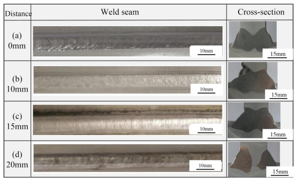
A quality weld and welded joint were obtained both in symmetric and asymmetric welding source of dual P-GMAW bilateral synchronous welding. During the asymmetric welding process, the distance between the two torches should exceed the length of the weld pool but be less than 20 mm, and in this paper, the distance of 15 mm was selected. When the distance between the two welding torches exceeded 20 mm, the molten pool was completely separated, and process pores were observed in the unfused root zone.
(4)
The hardness distribution of the welded joint was influenced by the thermal cycles. The hardness in WZ (about 80 HV) was larger than the HAZ in the base plate (65 HV) while lower than HAZ in the vertical plate (90 HV).
(5)
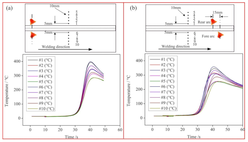
Comparing dual P-GMAW bilateral synchronous welding with a symmetric welding source, deformation of the welded joint during an asymmetric welding source was reduced by 20%, which was caused by the asymmetric welding thermal cycle on both sides of the base plate that was being welded.

Author Contributions

Conceptualization, Z.Y. and C.W.; methodology, C.W.; validation, Z.Y., C.W. and S.C.; investigation, H.Z.; resources, H.Z. and Y.Z.; data curation, Z.Y. and C.W.; writing—original draft preparation, Z.Y.; writing—review and editing, H.Z.; visualization, C.W. and S.C.; supervision, S.C.; funding acquisition, S.C. All authors have read and agreed to the published version of the manuscript.

Funding

This work is supported by National Natural Science Foundation of China (U1937207), R&D projects in key areas of Guangdong province (2018B090906004) and Major Science and Technology Innovation Project of Shandong Province (2019JZZY010452).

Institutional Review Board Statement

Not applicable.

Informed Consent Statement

Not applicable.

Data Availability Statement

Not applicable.

Conflicts of Interest

The authors declare no conflict of interest.

References

  1. Wang, H.; Liu, X.; Liu, L. Research on Laser-TIG Hybrid Welding of 6061-T6 Aluminum Alloys Joint and Post Heat Treatment. Metals 2020, 10, 130. [Google Scholar] [CrossRef] [Green Version]
  2. Yan, Z.Y.; Chen, S.J.; Jiang, F.; Zhang, W.; Tian, O.; Huang, N.; Zhang, S.L. Weld properties and residual stresses of VPPA Al welds at varying welding positions. J. Mater. Res. Technol. 2020, 9, 2892–2902. [Google Scholar] [CrossRef]
  3. Oliveira, J.P.; Curado, T.M.; Zeng, Z.; Lopes, J.G.; Rossinyol, E.; Park, J.M.; Kim, H.S. Gas tungsten arc welding of as-rolled CrMnFeCoNi high entropy alloy. Mater. Des. 2020, 189, 108505. [Google Scholar] [CrossRef]
  4. Oliveira, J.P.; Crispim, B.; Zeng, Z.; Omori, T.; Fernandes, F.B.; Miranda, R.M. Microstructure and mechanical properties of gas tungsten arc welded Cu-Al-Mn shape memory alloy rods. J. Mater. Process. Technol. 2019, 271, 93–100. [Google Scholar] [CrossRef]
  5. Memon, S.; Fydrych, D.; Fernandez, A.C.; Derazkola, H.A.; Derazkola, H.A. Effects of FSW tool plunge depth on properties of an Al-Mg-Si alloy T-joint: Thermomechanical modeling and experimental evaluation. Materials 2021, 14, 4754. [Google Scholar] [CrossRef] [PubMed]
  6. Sathish, T.; Tharmalingam, S.; Mohanavel, V.; Ashraff Ali, K.S.; Karthick, A.; Ravichandran, M.; Rajkumar, S. Weldability investigation and optimization of process variables for TIG-welded aluminium alloy (AA 8006). Adv. Mater. Sci. Eng. 2021, 2021. [Google Scholar] [CrossRef]
  7. Chen, J.; Schwenk, C.; Wu, C.S.; Rethmeier, M. Predicting the influence of groove angle on heat transfer and fluid flow for new gas metal arc welding processes. Int. J. Heat Mass Transf. 2012, 55, 102–111. [Google Scholar] [CrossRef]
  8. Ke, W.; Bu, X.; Oliveira, J.P.; Xu, W.; Wang, Z.; Zeng, Z. Modeling and numerical study of keyhole-induced porosity formation in laser beam oscillating welding of 5A06 aluminum alloy. Opt. Laser Technol. 2021, 133, 106540. [Google Scholar] [CrossRef]
  9. Kashaev, N.; Ventzke, V.; Fomichev, V. Effect of ND: YAG laser beam welding on weld morphology and mechanical properties of Ti–6Al–4V butt joints and T joints. Opt. Lasers 2016, 86, 172–180. [Google Scholar] [CrossRef]
  10. Chen, S.A.; Zhao, Y.Q.; Tian, S.H.; Gu, Y.Z.; Zhan, X.H. Study on keyhole coupling and melt flow dynamic behaviors simulation of 2219 aluminum alloy T-joint during the dual laser beam bilateral synchronous welding. J. Manuf. Process. 2020, 60, 200–212. [Google Scholar] [CrossRef]
  11. Squillace, A.; Prisco, U. Influence of filler material on micro- and macro-mechanical behaviour of laser-welded t-joint for aerospace applications. Proc. Inst. Mech. Eng. Part L J. Mater. Des. Appl. 2009, 223, 103–115. [Google Scholar] [CrossRef]
  12. He, E.; Gong, S.; Chen, L. Residual stress distribution feature for t-joints of aluminum-lithium alloy by double sided synchronization fiber laser welding. Rare Met. Mater. Eng. 2013, 42, 102–105. [Google Scholar]
  13. Yang, Z.; Tao, W.; Li, L. Numerical simulation of heat transfer and fluid flow during double-sided laser beam welding of T-joints for aluminum aircraft fuselage panels. Opt. Laser Technol. 2017, 91, 120–129. [Google Scholar] [CrossRef]
  14. Oliveira, P.I.; Costa, J.M.; Loureiro, A. Effect of laser beam welding parameters on morphology and strength of dissimilarAA2024/AA7075 T-joints. J. Manuf. Process. 2018, 35, 149–160. [Google Scholar] [CrossRef]
  15. Gomez, M.; Valles, P.; Medina, S.F. Evolution of microstructure and precipitation state during thermomechanical processing of a X80 microalloyed steel. Mater. Sci. Eng. A-Struct. Mater. Prop. Microstruct. Process. 2011, 528, 4761–4773. [Google Scholar] [CrossRef] [Green Version]
  16. Show, B.K.; Veerababu, R.; Balamuralikrishnan, R.; Malakondaiah, G. Effect of vanadium and titanium modification on the microstructure and mechanical properties of a microalloyed HSLA steel. Mater. Sci. Eng. A-Struct. Mater. Prop. Microstruct. Process. 2010, 527, 1595–1604. [Google Scholar] [CrossRef]
  17. Rusinek, A.; Klepaczko, J.R. Experiments on heat generated during plastic deformation and stored energy for TRIP steels. Mater. Des. 2009, 30, 1748–1761. [Google Scholar] [CrossRef]
  18. Yang, C.D.; Zhong, J.Y.; Chen, Y.X.; Chen, H.B.; Lin, T.; Chen, S.B. The realization of no back chipping for thick plate welding. Int. J. Adv. Manuf. Technol. 2014, 74, 79–88. [Google Scholar] [CrossRef]
  19. Qiang, W.; Wang, K.H.; Wang, S.Q.; Lu, Y.X.; Gao, Q. Forming characteristics and mechanism of double-sided heat source synergic vertical welding on an aluminum alloy. J. Manuf. Process. 2021, 64, 356–368. [Google Scholar] [CrossRef]
  20. Zhang, Y.M.; Zhang, S.B. Double-sided arc welding increases weld joint penetration. Weld. J. 1998, 77, 57–61. [Google Scholar]
  21. Shen, J.; You, G.; Long, S.; Pan, F. Abnormal macropore formation during double-sided gas tungsten arc welding of magnesium AZ91D alloy. Mater. Charact. 2008, 59, 1059–1065. [Google Scholar] [CrossRef]
  22. Yang, C.; Zhang, H.; Zhong, J. The effect of DSAW on pre-heating temperature in welding thick plate of high-strength low-alloy steel. Int. J. Adv. Manuf. Technol. 2014, 71, 421–428. [Google Scholar] [CrossRef]
  23. Gao, D.W. Investigation of Key Technology for Double-Sided arc MIG Welding on Medium Thick Aluminum Alloy Plate; Jilin University: Jilin, China, 2017. [Google Scholar]
  24. Duan, C.F.; Yang, S.L.; Gu, J.X.; Xiong, Q.; Wang, Y. Study on Microstructure and Fatigue Damage Mechanism of 6082 Aluminum Alloy T-Type Metal Inert Gas (MIG)Welded Joint. Appl. Sci. 2018, 8, 1741. [Google Scholar] [CrossRef] [Green Version]
  25. Miao, Y.G.; Yin, C.H.; Wei, C.; Li, C.W. An investigation on droplet transfer for bypass-current wire-heating PAW. J. Manuf. Process. 2021, 65, 355–363. [Google Scholar] [CrossRef]
  26. Hemmesi, K.; Mallet, P.; Farajian, M. Numerical evaluation of surface welding residual stress behavior under multi axial mechanical loading and experimental validations. Int. J. Mech. Sci. 2020, 168, 105127. [Google Scholar] [CrossRef]
  27. Song, Y.B.; Yang, X.Q.; Cui, L.; Hou, X.P.; Shen, Z.K.; Xu, Y. Defect features and mechanical properties of friction stir lap welded dissimilar AA2024–AA7075 aluminum alloy sheets. Mater. Design 2014, 55, 9–18. [Google Scholar] [CrossRef]
  28. Sato, Y.S.; Urata, M.; Kokawa, H.; Ikeda, K. Hall-Petch relationship in friction stir welds of equal channel angular-pressed aluminium alloys. Mater. Sci. Eng. A Struct. Mater. Prop. Microstruct. Process. 2003, 354, 298–305. [Google Scholar] [CrossRef]
  29. Zhao, Y. Forming Mechanism and Control Strategy of Aluminum Wire Arc Additive Manufacturing Based on CMT; Beijing University of Technology: Beijing, China, 2017. [Google Scholar]
  30. Fukuhara, N.; Agusa, K. Development of High-speed Automatic Welding Progress for Simultaneous Use on Inside and Outside Surfaces of Pipes. Weld. Int. 1997, 11, 46–51. [Google Scholar] [CrossRef]
  31. Ueda, Y.; Murakawa, H.; Ma, N. Welding Deformation and Residual Stress Prevention; Butterworth-Heinemann, Elsevier: Waltham, MA, USA, 2012. [Google Scholar]
  32. Heinze, C.; Schwenk, C.; Rethmeier, M. The effect of tack welding on numerically calculated welding-induced distortion. J. Mater. Process. Technol. 2012, 212, 308–314. [Google Scholar] [CrossRef]
Figure 1. Experimental setup and welding system.
Metals 11 01794 g001
Figure 2. Schematic diagram of welding torches and fillet weld, (a) front view, (b) top view, (c) the joint to be welded.
Metals 11 01794 g002
Figure 3. Schematic diagram of the angles and distances of torches, (a) front view, (b) top view.
Metals 11 01794 g003
Figure 4. Schematic diagram of weld area, (a) the joint to be welded, (b) the area to be welded.
Metals 11 01794 g004
Figure 5. Arc morphology and weld pool characteristics at different WFS, (a) 6 m/min, (b) 8 m/min, (c) 10 m/min, (df) the schematic diagram of (ac).
Metals 11 01794 g005
Figure 6. Welding current, arc voltage, and linear energy at different WFS.
Metals 11 01794 g006
Figure 7. Welded joints by single heat source, (a) 6 m/min, (b) 7 m/min, (c) 8 m/min, (d) 9 m/min, (e) 10 m/min.
Metals 11 01794 g007
Figure 8. Welds and welded joints at different WFS, (a) 8 m/min, (b) 9 m/min, (c) 9.5 m/min, (d) 10 m/min.
Metals 11 01794 g008
Figure 9. Weld pool characteristics at different root openings, (a) 0 mm, (b) 1 mm, (c) 2 mm, (d) 3 mm.
Metals 11 01794 g009
Figure 10. Welded joints at different root openings, (a) root opening: 0 mm, (b) root opening: 2 mm.
Metals 11 01794 g010
Figure 11. Welds and welded joints with different distance between the two torches on both sides, (a) 0 mm, (b) 10 mm, (c) 15 mm, (d) 20 mm.
Metals 11 01794 g011
Figure 12. Microstructure in the welded joint with unfused root, WFS is 9.5 m/min and the distance between the two torches is 20 mm, (b,c) are the corresponding microstructure in (a), (d) is the corresponding microstructure in (b).
Metals 11 01794 g012
Figure 13. Microstructure in the welded joint with full penetration, WFS is 9.5 m/min and the distance between the two torches is 15 mm, (a) welded joint, (b,c) and (e,f) are the corresponding microstructure in (a), (d) is the corresponding microstructure in (c).
Metals 11 01794 g013
Figure 14. Hardness distributions, (a) symmetric welding, WFS is 9.5 m/min and the distance between the two torches is 0 mm, (b) asymmetric welding, WFS is 9.5 m/min and the distance between the two torches is 15 mm.
Metals 11 01794 g014
Figure 15. Schematic diagram and weld photograph of welded joint deformation, (a) schematic diagram, (b) weld photograph.
Metals 11 01794 g015
Figure 16. Welding distortions with different welding conditions.
Metals 11 01794 g016
Figure 17. Welding thermal cycles, (a) symmetric welding, WFS is 9.5 m/min and the distance between the two torches is 0 mm, (b) asymmetric welding, WFS is 9.5 m/min and the distance between the two torches is 15 mm.
Metals 11 01794 g017
Table 1. Chemical composition of the 6082 aluminum alloy and ER5087 welding wire (wt %).
MaterialsSiMnMgFeCuTiCrAl
6082-T60.950.860.570.310.060.020.02Bal.
ER50870.060.774.890.280.020.070.10Bal.
Table 2. Welding parameters.
ParametersValue/Units
Travel speed (TS)2.0–6.0 m/min
Wire feed speed (WFS)
Wire diameter
Shielding gas
Shielding gas flow rate
Root opening
6.0–10.0 m/min
1.6 mm
Argon (99.999% purity)
15 L/min
0–3 mm
Table 3. Welding processes for different WFS.
WFS (m/min)678910
TS (mm/s)
Root opening: 0 mm
3.54.04.65.25.8
TS (mm/s)
Root opening: 1 mm
2.93.33.84.24.7
TS (mm/s)
Root opening: 2 mm
2.42.83.23.63.9
TS (mm/s)
Root opening: 3 mm
2.02.42.73.03.4
Publisher’s Note: MDPI stays neutral with regard to jurisdictional claims in published maps and institutional affiliations.

