Article

Minimizing the Negative Effects of Coolant Channels on the Torsional and Torsional-Axial Stiffness of Drills

1
AB Sandvik Coromant, 811 34 Sandviken, Sweden
2
Department of Engineering Science, University West, 461 86 Trollhättan, Sweden
3
Department of Mechanical Engineering, Blekinge Institute of Technology, 371 79 Karlskrona, Sweden
*
Author to whom correspondence should be addressed.
Metals 2021, 11(9), 1473; https://doi.org/10.3390/met11091473
Submission received: 6 July 2021 / Revised: 8 September 2021 / Accepted: 8 September 2021 / Published: 16 September 2021
(This article belongs to the Special Issue Modeling and Simulation of Metal Processing)

Abstract

:
Coolant channels allow internal coolant delivery to the cutting region and significantly improve drilling, but these channels also reduce the torsional and torsional-axial stiffness of the drills. Such a reduction in stiffness can degrade the quality of the drilled holes. The evacuation of cutting chips and the delivery of the cutting fluid put strict geometrical restrictions on the cross-section design of the drill. This necessitates careful selection and optimization of features such as the geometry of the coolant channels. This paper presents a new method that uses Prandtl’s stress function to predict the torsional and torsional-axial stiffness values. Using this method drills with one central channel are compared to those with two eccentric coolant channels, which shows that with the same cross-section area, the reduction of axial and torsional-axial stiffness is notably smaller for the design with two eccentric channels compared to a single central channel. The stress function method is further used to select the appropriate location of the eccentric coolant channels to minimize the loss of torsional and torsional-axial stiffness. These results are verified by comparison to the results of three-dimensional finite element analyses.

1. Introduction

Internal cutting fluid delivery in drilling brings the high-pressure cutting fluid very close to the rake and/or flank faces in the cutting zone and improves the operation by efficiently transferring heat and reducing the cutting-edge temperature. An increase of tool life or material removal rate in drills with internal coolant holes in the drilling of steels and cast iron is shown by Brockman et al. [1]. Oxford mentions increased feed rate, longer tool life, and the possibility of drilling deeper holes as an advantage of drills with coolant holes [2]. Internal coolant delivery pushes chips out of the drilled hole and prevents chip-clogging. The use of cutting fluids in drilling improves hole quality factors such as perpendicularity and cylindricity in drilling [3]. Reducing the drill’s temperature using the cutting fluid can also improve the drilling precision [4]. Furthermore, internal coolant supply allows higher cutting speeds while reducing undesirable effects such as subsurface grain deformation [5] and burrs [6] on the machined parts.
Internal cutting fluid delivery is possible with channels within the drill body running from the drill shank to the tip of the drill. Drills with internal coolant delivery channels are designed either with a central straight channel or with eccentric helical channels that follow the helical flutes. Creating coolant channels in a drill reduces its torsional and torsional-axial stiffness. Torsional stiffness determines how much a drill twists under an applied cutting torque. For a solid drill (without coolant holes), Oxford has shown that the torsional rigidity of a drill is dependent on the diameter of a circle that could be inscribed in the drill cross-section normal to its axis [2]. Torsional-axial stiffness determines how much that drill twists due to an axial load or how much its length changes due to an applied torque. The dimensional accuracy of a drilled hole is affected by deformations of the drill structure hence by the mentioned stiffness parameters.
The torsional-axial stiffness of a helical drill is caused by the pre-twist of the helical flute geometry which creates a coupling between torsion and elongation due to warping of the cross-section [7,8,9]. Bayly et al. in [10] showed that the coupling between torsional and axial directions in drills causes a self-induced vibration known as regenerative chatter vibration. In torsional-axial chatter, a sun-ray pattern is formed at the end of the hole which in combination with the cutting-edge movement affects the chip thickness and causes regenerative vibrations [10]. Torsional-axial chatter vibration in drilling is further discussed in [11,12,13,14,15]. A drill with a higher torsional-axial stiffness deflects less in the axial direction due to applied torques and therefore it has higher robustness against torsional-axial chatter. Although there are cases where vibrations can improve the drilling process [16,17,18], often it is desirable to minimize the dynamic deformations and vibrations in drilling.
To achieve higher torsional and torsional-axial stiffness, several approaches are proposed in the literature. By considering Prandtl’s analogy, De Beer in [19] pointed out the importance of the web thickness and mentions that a reduction in web thickness reduces the stiffness of a drill. According to Spur et al. [20], the distribution of the cross-section area affects the torsional stiffness via its effect on the polar second moment of the area ( I p ). Therefore, if the area is concentrated at the center, I p and consequently, the torsional stiffness is reduced [20]. From this, it was concluded that it is beneficial to place the coolant channel at the center of the drill to decrease the reduction of I p and hence the torsional stiffness. This suggestion is challenged in the current work, as it is shown that a twin-eccentric channel design has a higher stiffness. The reason is that I p only includes the effect of the area distribution and it does not consider the distribution of the shear stress over the cross-section.
Usually, during the design of a drill, several different design parameters must be optimized. While three-dimensional finite element analysis (3D FEA) could be used for the calculation of torsional and torsional-axial stiffness of drill designs with coolant channels, the 3D FEA is rather slow and thus generally unsuitable for design optimization of the location of the coolant channels along with other design parameters. Furthermore, 3D FEA does not provide a direct guideline for choosing the shape and location of the coolant channels. During design optimization, it is a good strategy to start with computationally efficient models, to obtain optimal values for some of the design parameters (such as coolant channel positions) as a function of other design parameters. This reduces the dimension of the design parameter space. By doing so, it becomes possible to make more iterations to find other design parameters such as the shape and size of chip evacuation channels. Given the computational advantage of the presented 2D method, the coolant channel positions could be immediately selected for any combination of other design parameters, allowing a higher number of iterations for those remaining design parameters.
To the best knowledge of the authors of this study, a fast guideline for positioning coolant channels has not been offered earlier in the literature. This paper attempts to fill this gap by using the two-dimensional Prandtl’s stress function method for stiffness prediction in drills with or without coolant channels which furthermore provides a guideline for the selection of the position of the coolant channels.
The study tasks of the present paper are formulated as the following questions:
  • How a 2D method could be established for the calculation of both the torsional and torsional-axial stiffness of a drill (with and without coolant channels)?
  • How precise is the 2D method in comparison to the 3D FEM in the calculation of the torsional and torsional-axial stiffness?
  • Can optimal positions for coolant channels be accurately estimated based on the presented 2D method?
Table 1 lists and describes symbols used in this paper.

2. Materials and Methods

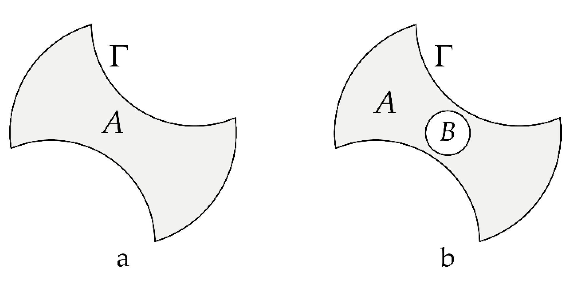
2.1. Modeling with Stress Function

Common drills can be categorized into drills with straight flutes, drills with helical flutes, and drills with variable cross-sections. A straight-flute drill has a constant cross-section and a zero-helix angle (zero pre-twist). It can be considered as a prismatic bar with a non-circular cross-section. In this case, the torsional stiffness of the drill ( K ϕ ϕ ) is equal to the torsional stiffness of the cross-section ( C ) in Nm2/rad, obtained from Prandtl’s stress function, divided by the length of the drill. A drill with helical flutes, i.e., with a nonzero helix angle, can be considered a pre-twisted beam. In this case, the torsional stiffness of the drill and the torsional stiffness of the cross-section do not have the same relationship as in straight tools; however, it is still reasonable to assume that higher torsional stiffness of the cross-section ( C ) also leads to a higher torsional stiffness in drills with helical flutes.
The variable cross-section drills, with the arbitrary variation of the cross-section along the drill axis, have the most general geometry, but due to the complexity of their modeling and their limited application, they are not covered here. In the most general form, the cross-section of a drill with a non-circular cross-section is represented by region A as shown in Figure 1.
Using Prandtl’s stress function, ψ , torsion of the noncircular cross-section A can be formulated with the following differential equation and its boundary condition [21]:
( 1 G ψ ) = 2 θ ,   ψ = 0   on   Γ
where θ is the amount of applied twist per unit length [21]. Γ is the external boundary of the cross-section as shown in Figure 1, and G is the shear modulus of the material [21]. For a constant   G over the cross-section, the partial differential equation, PDE, presented in Equation (1) becomes a Poisson equation with Dirichlet boundary conditions. This equation has analytical solutions on simple domains such as elliptic, triangular, and rectangular cross-sections [22]; however, it has no analytical solution for the complex geometry of drills including coolant channels. Therefore, numerical methods, such as the 2D finite element method, are used to solve this equation [21]. After calculating the stress function, the torque, T , is calculated as follows [21]:
T = 2 A ψ d A
The torsional stiffness of the cross-section, C , is defined as [21]:
C = T θ  
Since θ is in rad / m , the unit of C is Nm 2 / rad . C is numerically equal to the amount of torque needed to twist the beam of unit length, one radian.

2.2. Torsional-Axial Coupling

According to Hodges, the amount of this twist, ϕ , when an axial force, F z , is applied on a helical beam with a pre-twist of β , is related to F z as [8]:
( G J + F z I p A ) ϕ = F z A ( I p J ) β    
I p is the second polar moment of area, J is defined as the ratio C / G . The torsional-axial stiffness ( K ϕ z ) is equal to F z / ϕ . Since F z is present on both sides of Equation (4), it is difficult to separate F z / ϕ from the rest of the equation; however, generally G J F z I p / A , since while J and I p have the same order of magnitude, G is tens of gigapascals while F z / A is usually much smaller. From Equation (4) the following approximate relationship is obtained:
K ϕ z = F z ϕ G A ( I p / J 1 ) β    
According to Equation (5), the magnitude of the torsional-axial stiffness is proportional to ( I p / J 1 ) 1 . The minimum possible value for I p / J is 1 which is achieved by a circular cross-section, otherwise I p / J > 1   and therefore ( I p / J 1 ) > 0 . To obtain the maximum magnitude of the torsional-axial stiffness,   I p / J should be minimized.
The relationship between the shear stress components and Prandtl’s stress function is shown in Equation (6) [21]:
τ x z = ψ y τ y z = ψ x
The boundary condition   ψ = 0 , given in Equation (1), applies to the external boundary only. With the presence of coolant channels in the cross-section, ψ is constant on the boundaries of the channels (holes), but not necessarily zero [23]. In this case, to solve Equation (1) one approach is to assume that the holes are filled with a material with a very low shear modulus compared to the material of the beam [23,24]. This way, Equation (1) could be used to solve the equation over the multi-connected domain, Figure 1b, and in regions representing holes ( B ), the small shear modulus is applied.

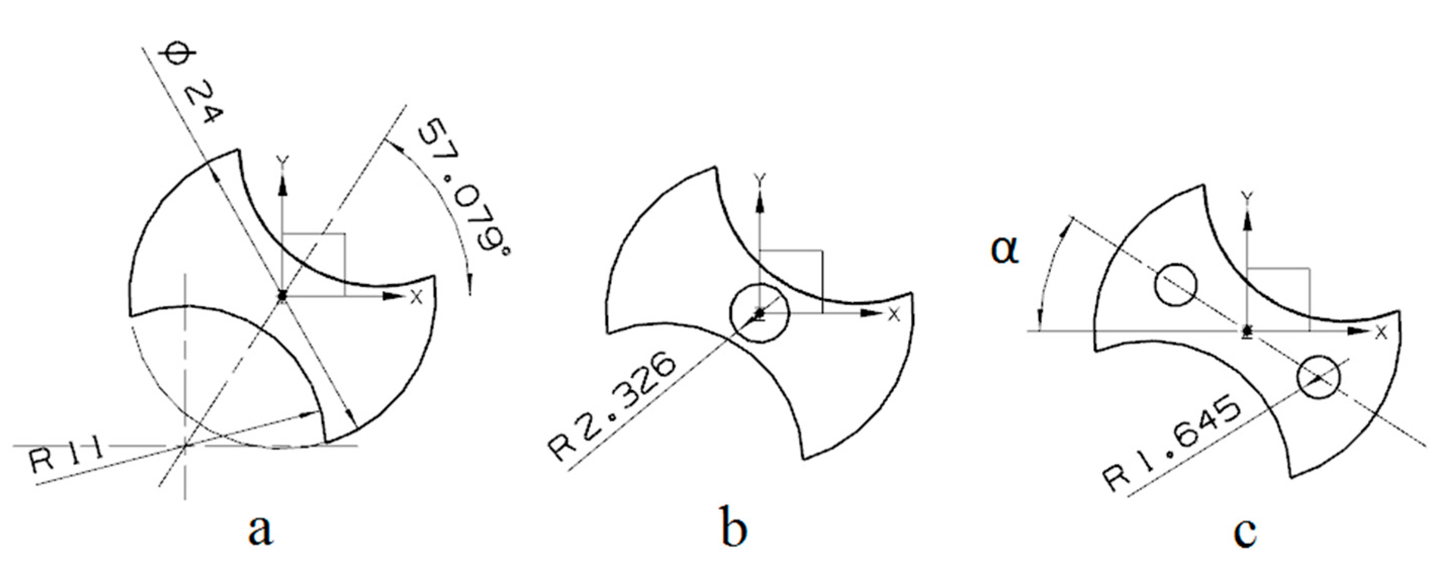
2.3. Optimal Eccentric Coolant Channel Positioning

In regions with small shear stress, the drill material contributes very little to torsional energy storage thus it is reasonable to remove material from these regions to create coolant channels. According to Equations (6) and (7), the minimum shear happens at saddle points or extrema of the stress function ψ ; therefore, in our proposed method, the coolant channels should be positioned on these extrema regions.

3. Results

In this section, first, the results of the 2D investigation are presented and compared to the result of the 3D finite element simulation. After that, the 2D method is used for investigating the effects of design parameters. To compare different designs, the following parameters are selected, diameter: 24 mm, length of the twisted section: 240 mm, and total uniform pre-twist angle of 417.1°. It is also assumed that the drills are made of typical steel, with a modulus of elasticity of 200 GPa and a Poisson’s ratio of 0.3. The cross-section of a typical drill without any coolant channel is shown in Figure 2a. This design is referred to as the “solid drill” in this paper. Drills with coolant channels often either have one central channel (Figure 2b) or two eccentric channels in opposite directions; as shown in Figure 2c. For drills with coolant channels a typical total coolant channel area of 17 mm 2 is selected, which results in channel radii of 2.326 mm and 1.645 mm for the single-channel and two-channel designs, respectively, as shown in Figure 2.

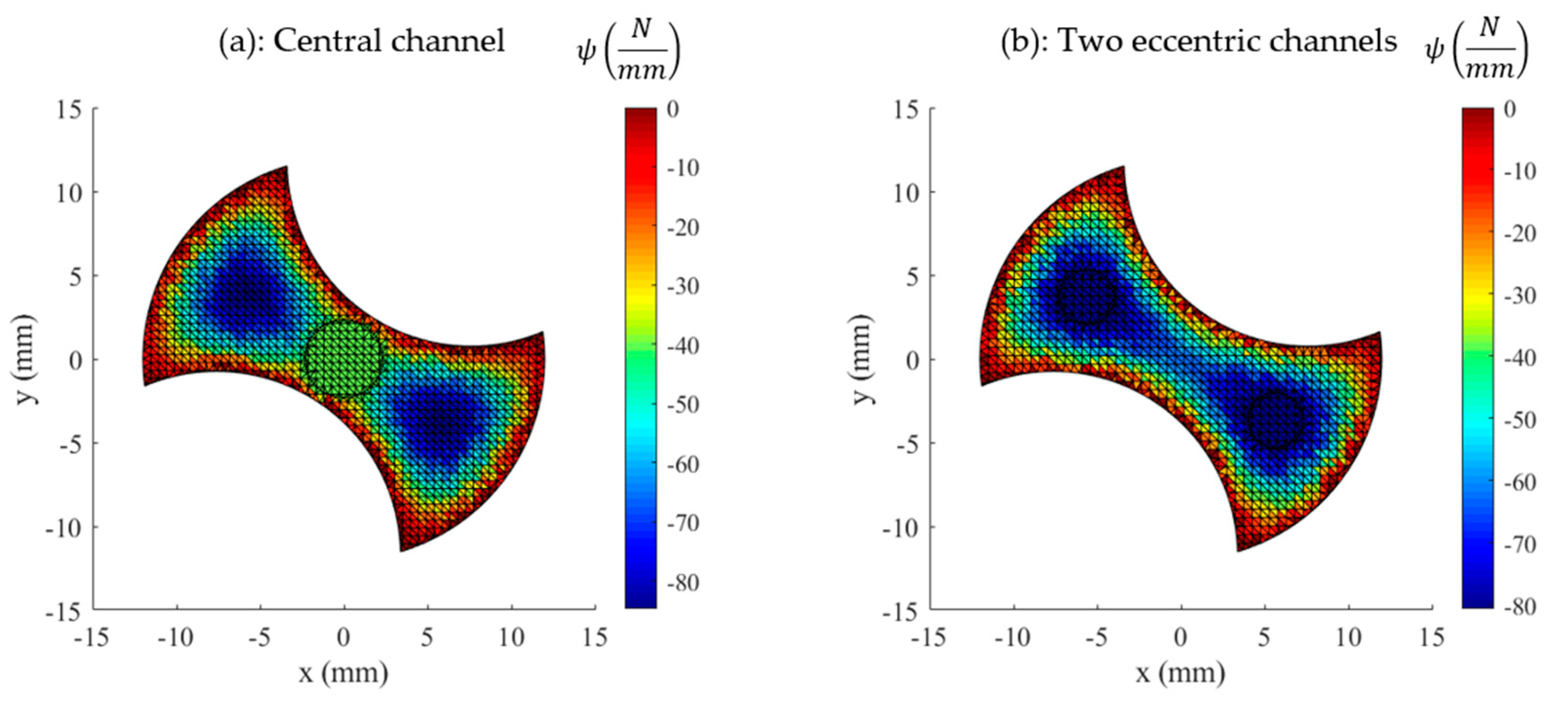
3.1. Stiffness Calculation Using Prandtl’s Stress Function

To calculate the stiffness values, the torque to cause a 1° ( = π / 180   rad )   torsion per 240 mm is calculated. Prandtl’s stress function is obtained by solving Equation (1) numerically which leads to the result shown in Figure 3 for the solid drill. For this drill, a torque of 19.99 Nm is calculated according to Equation (2), which corresponds to the torsional stiffness of 1145 Nm/rad. Using Equation (3) the torsional stiffness of the cross-section, C , is calculated as 274.9 Nm2/rad.
With a single central channel, Prandtl’s stress function is calculated as shown in Figure 4a. In this case, an 18.54 Nm torque is required to achieve the mentioned torsion. Thus, the torsional stiffness is calculated as 1062 Nm/rad which is 7.3% lower than the solid drill.
With two eccentric coolant channels, to minimize the negative effect of the channels on the torsional stiffness of the cross-section, these channels are placed at positions where the magnitude of shear stress due to torsion is small. From Equation (6), it is concluded that the shear stress components are zero at the saddle point at the center and the two local minima which are shown in Figure 3. If the channels are placed at the local minima, the obtained Prandtl’s stress function is calculated as shown in Figure 4b. For this case, to twist the drill 1°, a torque of 19.83 Nm is needed, corresponding to the torsional stiffness of 1136 Nm/rad, which is only 0.8% lower than the torsional stiffness of the solid drill.

3.2. Comparison to 3D Finite Element

A three-dimensional finite element analysis (3D FEA) implemented in a commercial software package (Ansys) is used to evaluate the results obtained from the 2D stress function method. The drill designs are meshed using ten-node tetrahedral (TET10) elements. Fixed (all degrees of freedom) boundary condition is assumed on the surface of the cylindrical shank of the drills, resembling the connection condition in a high-stiffness tool holder. Finally, a 1 Nm torque is applied on the top surface of the drills. The torsional and torsional-axial stiffness values are calculated using the displacement results for this force application.

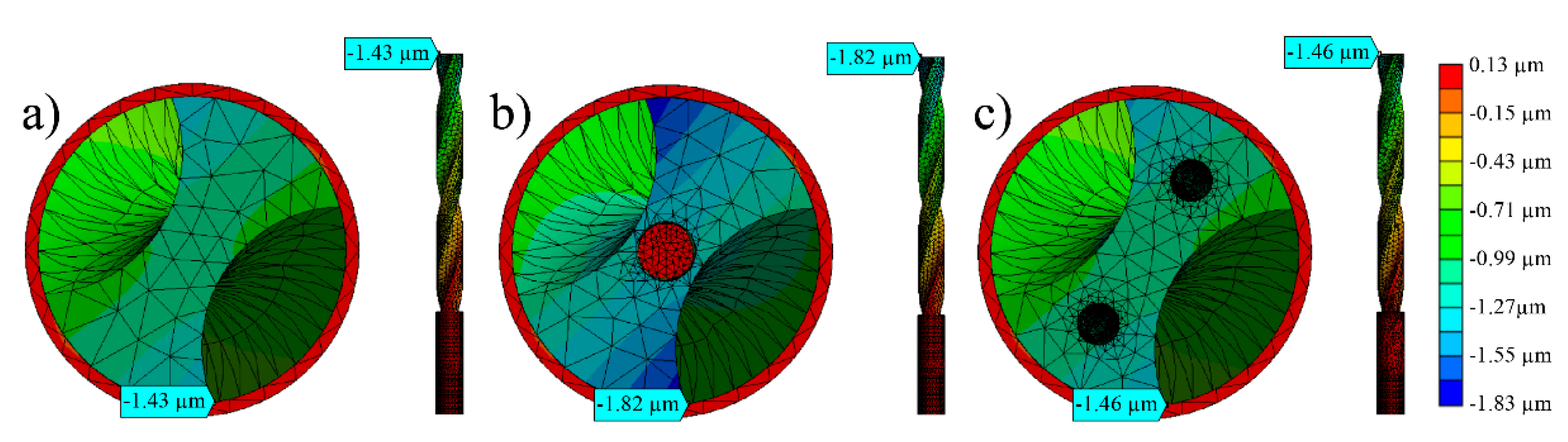
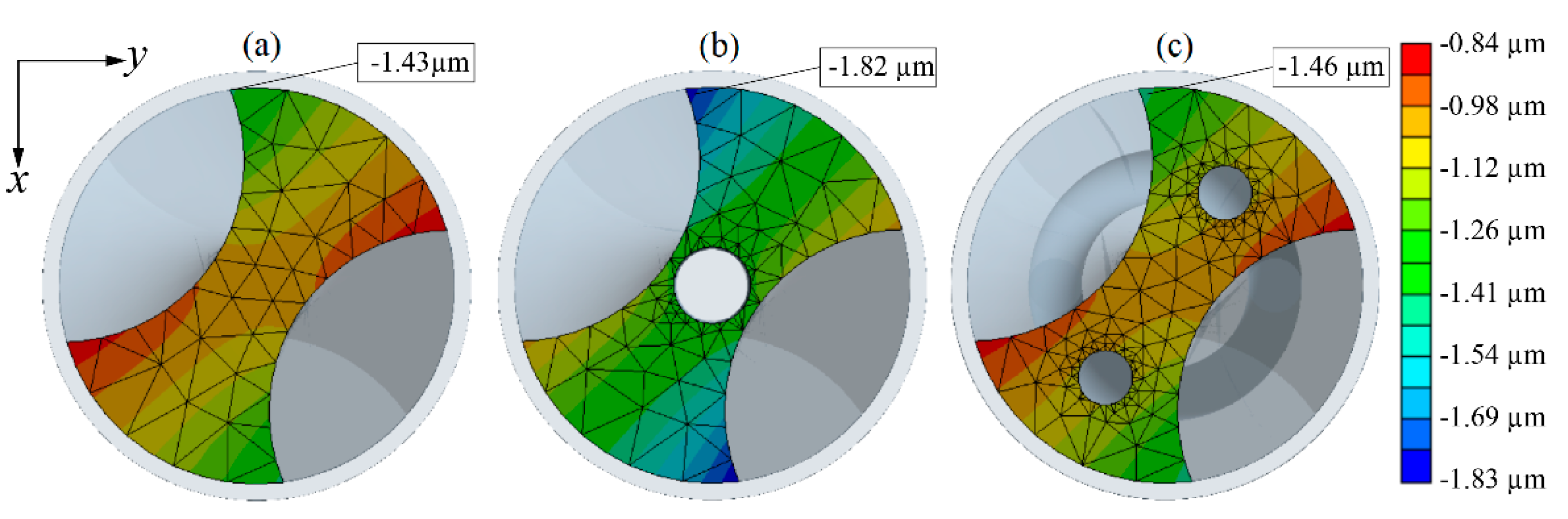
3.2.1. Torsional Stiffness

Figure 5 presents the tangential displacements calculated by the 3D FEA. To calculate the torsional stiffness of each drill, the rotation angle on the top surface is obtained by dividing tangential displacement on the peripheral corner by the radius of the drill, 12 mm. The resulting torsional stiffness values are presented in Table 2 and compared to the results of the 2D method. The 3D FEM results show that the torsional stiffness of the single-channel drill reduces more significantly (9.7%) compared to the two-channel drill where the reduction is relatively negligible (1.1%). A rather similar trend was also predicted by the 2D method using Prandtl’s stress function, with slightly different numbers, i.e., 7.3% and 0.8% reduction for the single-channel and two-channel drills, respectively.
The stiffness values calculated using 3D FEA, for all drill designs are about 10% higher than those calculated by the 2D method. This is due to the assumption of a zero-twist angle in the 2D calculations with Prandtl’s stress function. Figure 6 shows how torsional stiffness increases when the twist angle increases according to the 3D FEA simulation for the solid drill. As it is shown, the stiffness obtained by 3D FEA approaches the 2D result as the total twist approaches zero.

3.2.2. Torsional-Axial Stiffness

Figure 7 shows the axial deformation of drills due to the application of 1 Nm torque. Negative values for the axial deformations indicate the length reduction as the torque is applied in the direction of the helix and opposite to the direction of the cutting torque. This shows that, at its extreme, the magnitude of axial deformation increases by 27% for the single-channel drill and by only 2.1% for the two-channel drill compared to the solid drill.
Axial deformation (warping) of the top surface of drills is shown in Figure 8. This figure shows that the two-channel drill’s deformation is very close to the deformation of the solid drill and considerably less than the deformation of the single-channel drill. This indicates that the torsional-axial stiffness also reduces slightly for the two-channel design.
Table 3 compares the torsional-axial stiffness as estimated from the 2D method (Equation (5)) and the results of the 3D FEA. As shown in Figure 8, as the top surfaces of all drills warp due to the twisting torque, the displacements of the top surface are not a single value; therefore, in the case of the 3D FEM, the average of maximum and minimum displacements are used to calculate the torsional-axial stiffness. As can be seen, reduction in torsional-axial stiffness is negligible (−1.8%) when the two-channel design is used and much pronounced for the single-channel design (19.8%); and similar to the torsional stiffness, the 3D FEA calculates 7–12% higher values for the torsional-axial stiffness compared to the 2D method.

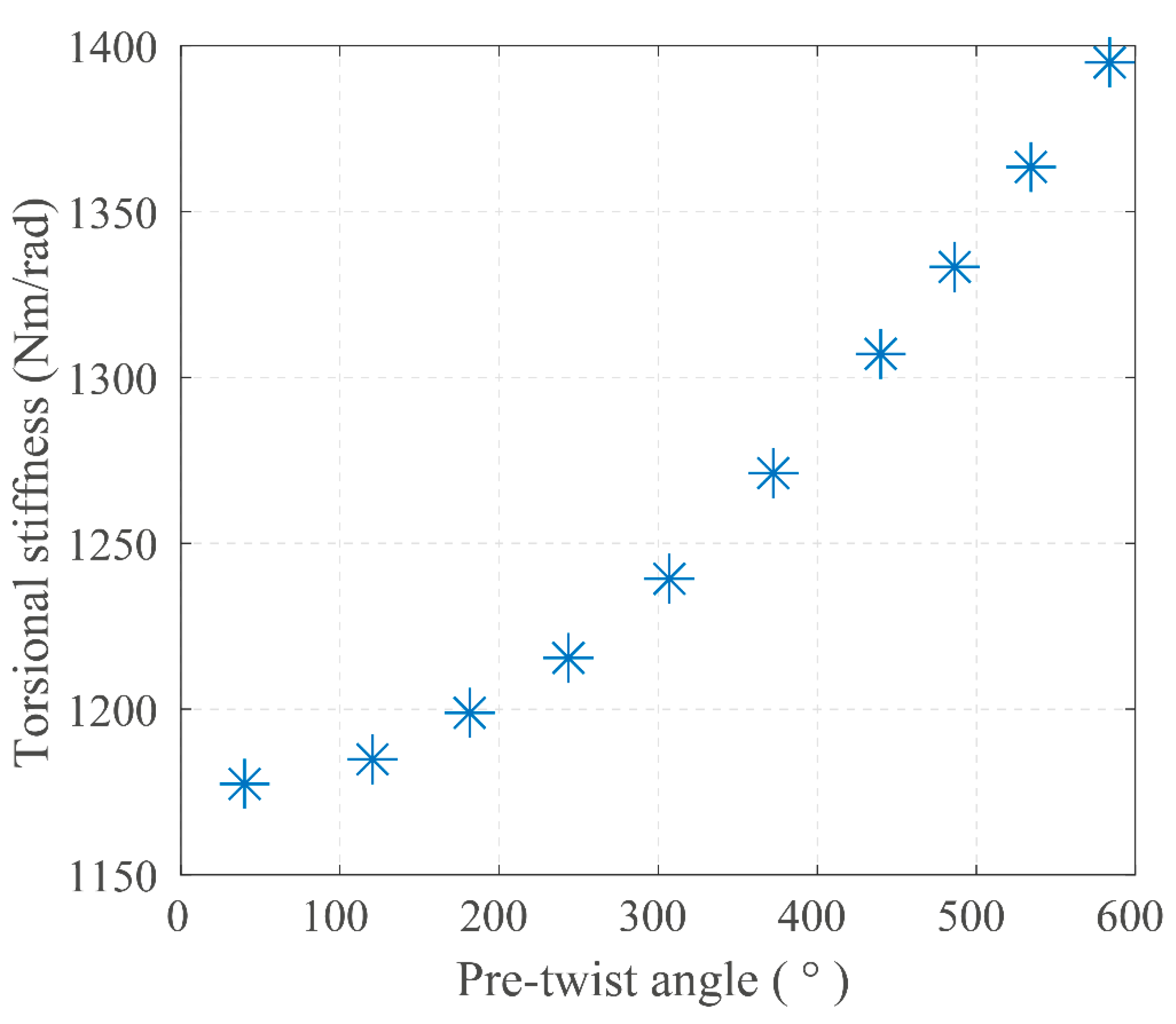
3.3. Effects of Design Parameters on Stiffness

The effect of the coolant channel’s cross-section area on the torsional stiffness is shown in Figure 9 for both single-channel and two-channel designs, which shows the superiority of the later design in terms of torsional stiffness for other coolant area values as well.
The reduction of the stiffness, due to coolant channels, is affected by the channel positions. Figure 10 shows the reduction of the torsional and the torsional-axial stiffness of the two-channel drill, as the upper coolant hole moves radially along the dash-dot line shown in Figure 2c. This line passes through the drill’s center and the local minimum which is shown in Figure 3 and since the cross-section is symmetric it also passes through the lower channel’s center. As observed from Figure 10, the maximum torsional stiffness is achieved if the center of the coolant channel has a radial distance of approximately 7 mm which is close to the radial distance of the upper local minimum shown in Figure 3. Figure 10 also shows that for torsional-axial stiffness, the radial position to achieve the minimum reduction is slightly larger which is due to the effect of the coolant channels on I p . As mentioned earlier, to maximize the torsional-axial stiffness, the ratio between I p and J , i.e., I p / J , must be minimized. If I p was independent of the location of the channels, this ratio could be minimized by maximizing J , hence the same result as torsional stiffness could be obtained. However, since I p decreases as the hole moves away from the center—a direct conclusion from the formula for the second moment of the area—minimum reduction of torsional-axial stiffness occurs at a slightly higher radial distance compared to the torsional stiffness.

4. Discussion

The solution of Prandtl’s stress function for a solid drill (Figure 3) helped in the selection of the optimal coolant channel position for the drill with twin eccentric channels. The stress function investigation also showed that the reduction in stiffness is much smaller for the twin-channel design compared to the drill with a single central channel. These results were confirmed with 3D finite element analysis as shown in Table 2 and Table 3; however, the values predicted by the 3D FEA were always 8–14% higher than those predicted by the 2D solution. It was shown in Figure 6 that the results of the 3D simulation would approach the results of the stress function method if the twist angle was reduced to zero. In other words, the approximation caused by ignoring the pre-twist angle in 2D calculations explains the lower torsional stiffness values obtained compared to the results of the 3D FEA. In the case of the torsional-axial stiffness, the pre-twist angle is included in the 2D calculations, see Equation (5), but other approximations included in the derivation equation could be the source of the disagreement.
It was also shown that placement of the coolant channels on the extrema of Prandtl’s stress function results in a minimal reduction of the torsional stiffness as moving the coolant channel from those positions would lead to a higher reduction in stiffness, as shown in Figure 10. The torsional-axial stiffness reaches the best condition at points slightly farther, because of the effect of the holes on the polar second moment of area, I p ; however, this effect is negligible, and the proposed method efficiently mitigates the effect of coolant channels on the torsional-axial stiffness as well.
To the knowledge of the authors, the 2D method for finding the optimal positions for the coolant channels is introduced for the first time in this paper. The method has a low computational cost, compared to multiple iterations with 3D Finite Element Analysis, which makes it a suitable method for batch simulation and evaluation of several different drilling tools.
There are few assumptions in the proposed method which should be considered in extending its application. The method assumes an isotropic and homogenous drill body material with a linear elastic behavior. It further assumes that the manufacturing process of the coolant channels does not change the material behavior.
While this study shows that eccentric coolant channels are advantageous in terms of torsional and torsional-axial stiffness of helical drills, they should be made as helical channels with the same pitch as the flutes. Manufacturing these helical channels is more complex and costly compared to the manufacturing of a single central straight channel; this may motivate the selection of the later design in some applications.

5. Conclusions

In summary, the following conclusions are made:
(1)
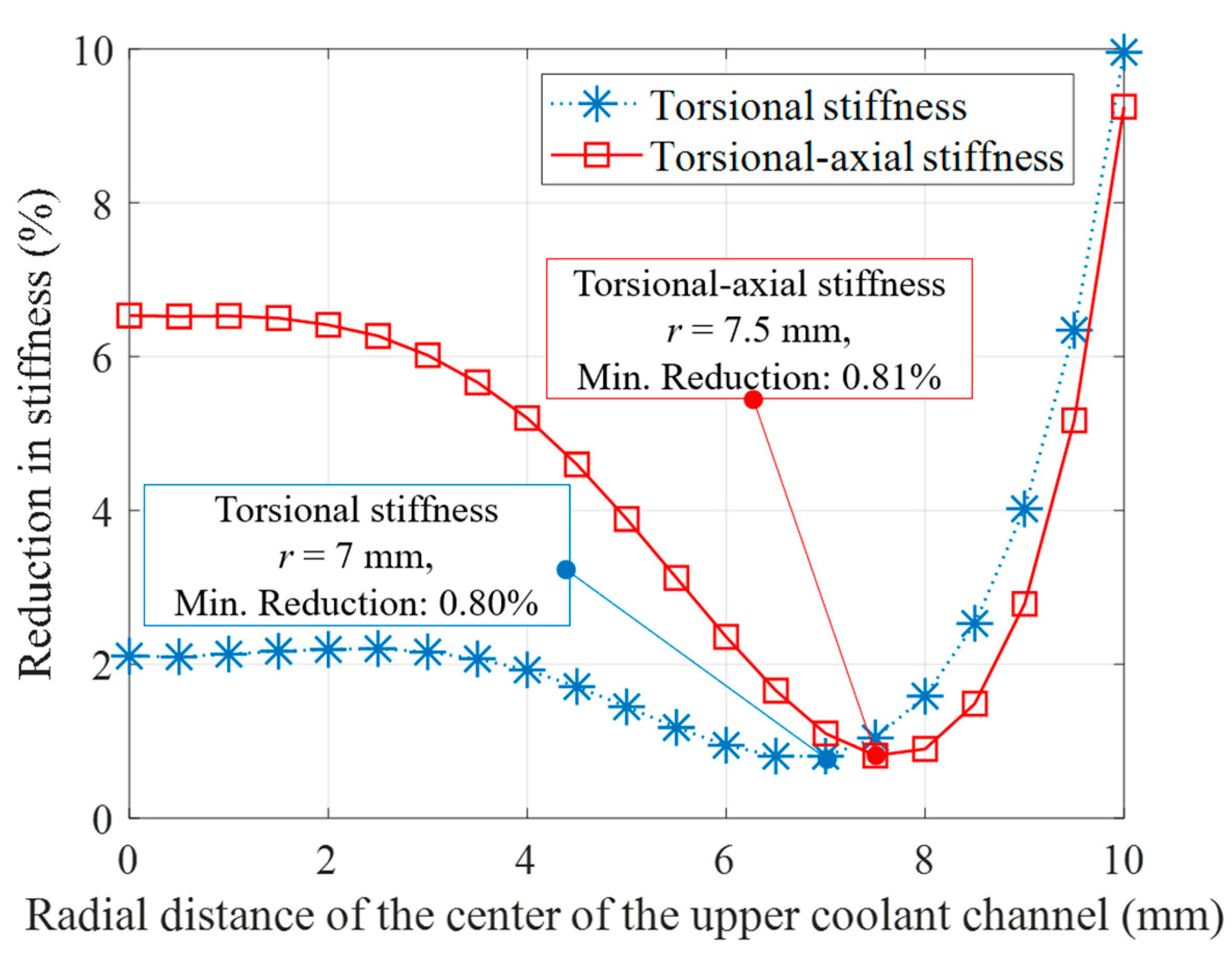
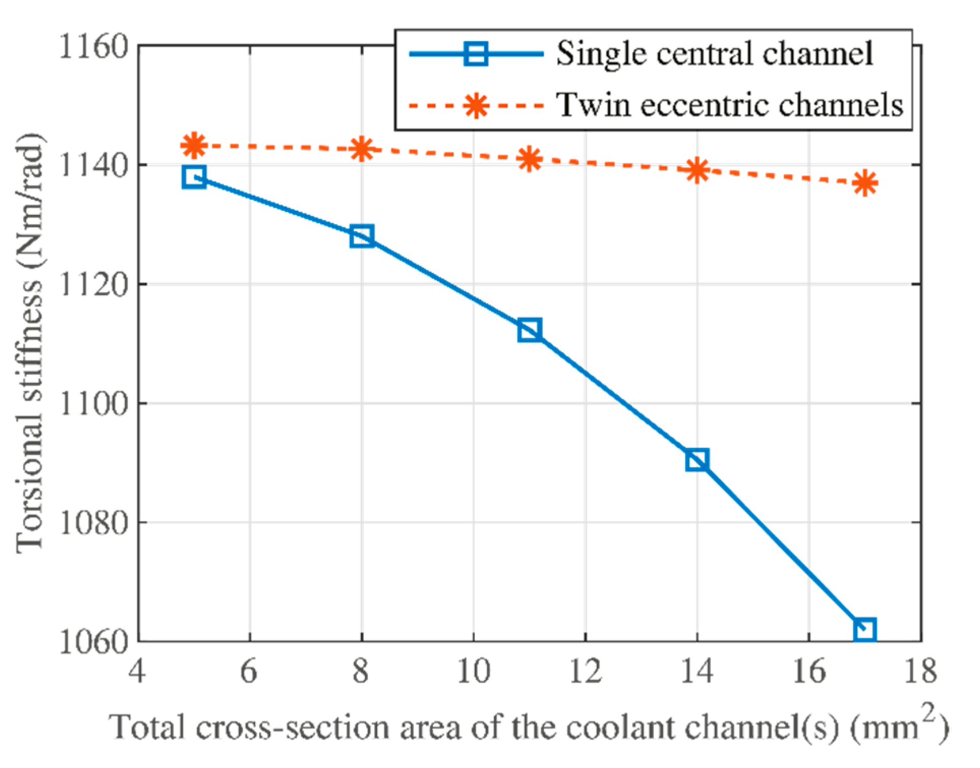
The novel method of placement of the coolant channels around the minima of Prandtl’s stress function leads to the minimum reduction of the torsional stiffness. As an example, as shown in Figure 10, a 0.80% reduction in optimum condition is achieved while for a non-optimal positioning the stiffness is reduced by about 10%. The minimum reduction of the torsional-axial stiffness (0.81%) is achieved at a negligibly larger radial position (about 0.5 mm in a 12 mm radius).
(2)
The predictions of the 2D method in terms of superiority of eccentric channel design are confirmed with the slower 3D Finite Element Analysis. Due to ignoring the pre-twist angle in the 2D calculation of torsional stiffness and other simplifying assumptions, the 2D method predicts slightly (8–14%) lower stiffness values compared to the 3D FEA.
(3)
The present 2D significantly improves the optimal design parameter selection in the design of drills with coolant channels by simplifying the optimization problem via effectively reducing the number of design parameters that need optimization.

Author Contributions

Conceptualization, A.P.; methodology, A.P., M.E.; software, A.P.; validation, A.P.; formal analysis, A.P.; investigation, A.P.; resources, A.P., T.B., M.M.; data curation, A.P.; writing-original draft preparation, A.P.; writing-review and editing, T.B., M.M., M.E., A.P.; visualization, A.P.; supervision, T.B., M.M., M.E.; project administration, T.B., M.M.; funding acquisition, T.B., M.M. All authors have read and agreed to the published version of the manuscript.

Funding

This research was funded by “Stiftelsen för Kunskaps- och Kompetensutveckling” and Sandvik Coromant. Further support from the Research School of Simulation and Control of Material affecting Processes (SiCoMaP) at University West, Sweden is greatly appreciated.

Institutional Review Board Statement

Not applicable as the study did not involve humans or animals.

Informed Consent Statement

Not applicable since the study did not involve humans.

Conflicts of Interest

The first author of this paper is employed by a cutting tool manufacturer which also produces drills with coolant channels.

References

  1. Brockman, R.W.; Burant, R.O.; Kennedy, R.G.; Marrotte, N.W.; Sikora, R.E. Drill Design and Application Requirements for Optimum Coolant-Feeding Twist Drill Usage; Technical Paper MR67-104; American Society of Tools and Manufacturing Engineers (ASTME, now SME): Southfield, MI, USA, 1967; pp. 1–15. [Google Scholar]
  2. Oxford, C.J. A review of some recent developments in the design and application of twist drills. Adv. Mach. Tool Des. Res. 1967, 845–861. [Google Scholar]
  3. Haan, D.; Batzer, S.; Olson, W.; Sutherland, J. An experimental study of cutting fluid effects in drilling. J. Mater. Process. Technol. 1997, 71, 305–313. [Google Scholar] [CrossRef]
  4. Bono, M.; Ni, J. The effects of thermal distortions on the diameter and cylindricity of dry drilled holes. Int. J. Mach. Tools Manuf. 2001, 41, 2261–2270. [Google Scholar] [CrossRef]
  5. Eynian, M.; Das, K.; Wretland, A. Effect of tool wear on quality in drilling of titanium alloy Ti6Al4V, Part I: Cutting Forces, BurrFormation, Surface Quality and Defects. High Speed Mach. 2017, 3, 1–10. [Google Scholar] [CrossRef] [Green Version]
  6. Das, K.; Eynian, M.; Wretland, A. Effect of tool wear on quality in drilling of titanium alloy Ti6Al4V, Part II: Microstructure and Microhardness. High Speed Mach. 2017, 3, 11–22. [Google Scholar] [CrossRef]
  7. Astakhov, V.P. Drills: Science and Technology of Advanced Operations; CRC Press: Boca Raton, FL, USA, 2015. [Google Scholar]
  8. Hodges, D.H. Torsion of pretwisted beams due to axial loading. J. Appl. Mech. 1980, 47, 393–397. [Google Scholar] [CrossRef]
  9. Filiz, S.; Bediz, B.; Romero, L.A.; Ozdoganlar, O.B. Three dimensional dynamics of pretwisted beams: A spectral-Tchebychev solution. J. Sound Vib. 2014, 333, 2823–2839. [Google Scholar] [CrossRef]
  10. Bayly, P.V.; Metzler, S.A.; Schaut, A.J.; Young, K.A. Theory of torsional chatter in twist drills: Model, stability analysis and composition to test. J. Manuf. Sci. Eng. 2001, 123, 552–561. [Google Scholar] [CrossRef]
  11. Ahmadi, K.; Altintas, Y. Stability of lateral, torsional and axial vibrations in drilling. Int. J. Mach. Tools Manuf. 2013, 68, 63–74. [Google Scholar] [CrossRef]
  12. Roukema, J.C.; Altintas, Y. Time domain simulation of torsional-axial vibrations in drilling. Int. J. Mach. Tools Manuf. 2006, 46, 2073–2085. [Google Scholar] [CrossRef]
  13. Parsian, A. Dynamics of Torsional and Axial Vibrations in Indexable Drills; University West: Trollhättan, Sweden, 2015. [Google Scholar]
  14. Parsian, A.; Magnevall, M.; Beno, T.; Eynian, M. Time-Domain Modeling of Torsional-Axial Chatter Vibrations in Indexable Drills with Low Damping. In Proceedings of the 4th International Conference on Virtual Machining Process Technology, Vancouver, BC, Canada, 2–5 June 2015. [Google Scholar]
  15. Parsian, A.; Magnevall, M.; Eynian, M.; Beno, T. Time domain simulation of chatter vibrations in indexable drills. Int. J. Adv. Manuf. Technol. 2017, 89, 1209–1221. [Google Scholar] [CrossRef] [Green Version]
  16. Peigné, G.; Kamnev, E.; Brissaud, D.; Gouskov, A. Self-excited vibratory drilling: A dimensionless parameter approach for guiding experiments. Proc. Inst. Mech. Eng. Part B J. Eng. Manuf. 2005, 219, 73–84. [Google Scholar] [CrossRef]
  17. Chang, S.S.F.; Bone, G.M. Thrust force model for vibration-assisted drilling of aluminum 6061-T6. Int. J. Mach. Tools Manuf. 2009, 49, 1070–1076. [Google Scholar] [CrossRef]
  18. Kumar, M.N.; Subbu, S.K.; Krishna, P.V.; Venugopal, A. Vibration Assisted Conventional and Advanced Machining: A Review. Procedia Eng. 2014, 97, 1577–1586. [Google Scholar] [CrossRef] [Green Version]
  19. De Beer, C. The web thickness of twist drills. Ann. CIRP 1970, 18, 81–85. [Google Scholar]
  20. Spur, G.; Masuha, J.R. Drilling with Twist Drills of Different Cross Section Profiles. CIRP Ann. Manuf. Technol. 1981, 30, 31–35. [Google Scholar] [CrossRef]
  21. Ottosen, N.S.; Petersson, H. Introduction to the Finite Element Method; Prentice-Hall: New York, NY, USA, 1992. [Google Scholar]
  22. Francu, J.; Novackova, P.; Janicek, P. Torsion of a non-circular bar. Eng. Mech. 2012, 19, 45–60. [Google Scholar]
  23. Ely, J.F.; Zienkiewicz, O.C. Torsion of compound bars—A relaxation solution. Int. J. Mech. Sci. 1960, 1, 356–365. [Google Scholar] [CrossRef]
  24. Zienkiewicz, O.C.; Taylor, R.; Zhu, J.Z. The Finite Element Method: Its Basis and Fundamentals; Butterworth-Heinemann: Amsterdam, The Netherlands, 2005. [Google Scholar]
Figure 1. A drill cross-section, A, with the boundary Γ . (a) without hole, (b) with a hole, B.
Metals 11 01473 g001
Figure 2. Typical drill cross-sections: (a) solid drill (b) with a single coolant channel (c) with two coolant channels. Drills with coolant channels have total hole areas equal to 17 mm2. (Length parameters are in mm.)
Metals 11 01473 g002
Figure 3. Prandtl’s stress function ψ for the cross-section shown in Figure 2a; in local minima points, the shear stress components (derivatives of Prandtl’s stress function) are zero.
Metals 11 01473 g003
Figure 4. Prandtl’s stress function ( ψ ), for drills with (a) a single central coolant channel and (b) twin eccentric channels placed at the minima shown in Figure 3.
Metals 11 01473 g004
Figure 5. Tangential displacement with 3D FEA for the (a) solid drill (max: 9.21 μm), (b) drill with a central channel (max: 10.21 μm), (c) two-channel drill (max: 9.31 μm).
Metals 11 01473 g005
Figure 6. Torsional stiffness versus total pre-twist angle for the solid drill, according to the 3D FEM model.
Metals 11 01473 g006
Figure 7. Axial displacement in meters calculated by 3D FEM for the (a) solid drill (max: 1.43 μm), (b) drill with a central channel (max: 1.82 μm), (c) two-channel drill (max: 1.46 μm).
Metals 11 01473 g007
Figure 8. Axial deformation (warping) of the top surface as calculated by the 3D FEM (a) solid drill (max: 1.43 μm), (b) drill with a central channel (max: 1.82 μm), (c) two-channel drill (max: 1.46 μm).
Metals 11 01473 g008
Figure 9. Torsional stiffness versus total cross-section area of the coolant channels.
Metals 11 01473 g009
Figure 10. Reduction in torsional and torsional-axial stiffness versus the radial position of the upper coolant channel.
Metals 11 01473 g010
Table 1. Nomenclature.
SymbolUnitDescription
A m 2 Cross-section of the drill
C Nm 2 / rad Torsional stiffness of the cross-section
D mThe diameter of the drill
F z N Axial force
G Pa Shear modulus
I p m 4 The polar second moment of area
J m 4 The ratio of torsional stiffness to shear modulus J = C / G
K ϕ ϕ Nm / rad Torsional stiffness
K ϕ z = K z ϕ N Torsional-axial stiffness
L m Length of the drill
T Nm Torque
β rad Pre-twist in the structure
Γ -The Boundary of the cross-section
θ rad / m Twist per unit length
τ x z , τ y z Pa Components of the shear stress
ϕ rad Twist due to the axial force
ψ N / m Prandtl’s stress function
Table 2. Torsional stiffness calculated by the 2D method and 3D FEA.
Parameter2D3D FEA
Torsional Stiffness, solid drill (Nm/rad)11451303
Torsional Stiffness, single-channel drill (Nm/rad)10621176
Torsional Stiffness change, single-channel drill vs. solid drill−7.3%−9.7%
Torsional Stiffness, two-channel drill (Nm/rad)11361289
Torsional Stiffness change, two-channel drill vs. solid drill−0.8%−1.1%
Table 3. Torsional-axial stiffness calculated using the 2D method and the 3D FEM.
Parameter2D3D FEM
Torsional Axial Stiffness, solid drill (kN)777876
Torsional Axial Stiffness, single-channel drill (kN)653703
Torsional-Axial Stiffness change, single-channel drill vs. solid drill−16%−19.8%
Torsional Axial Stiffness, two-channel drill (kN)766861
Torsional-Axial Stiffness change, two-channel drill vs. solid drill−1.4%−1.8%
Publisher’s Note: MDPI stays neutral with regard to jurisdictional claims in published maps and institutional affiliations.

