
Experimental Investigation of Material Properties in FSW Dissimilar Aluminum-Steel Lap Joints


Abstract
:1. Introduction
2. Materials and Methods
2.1. Materials
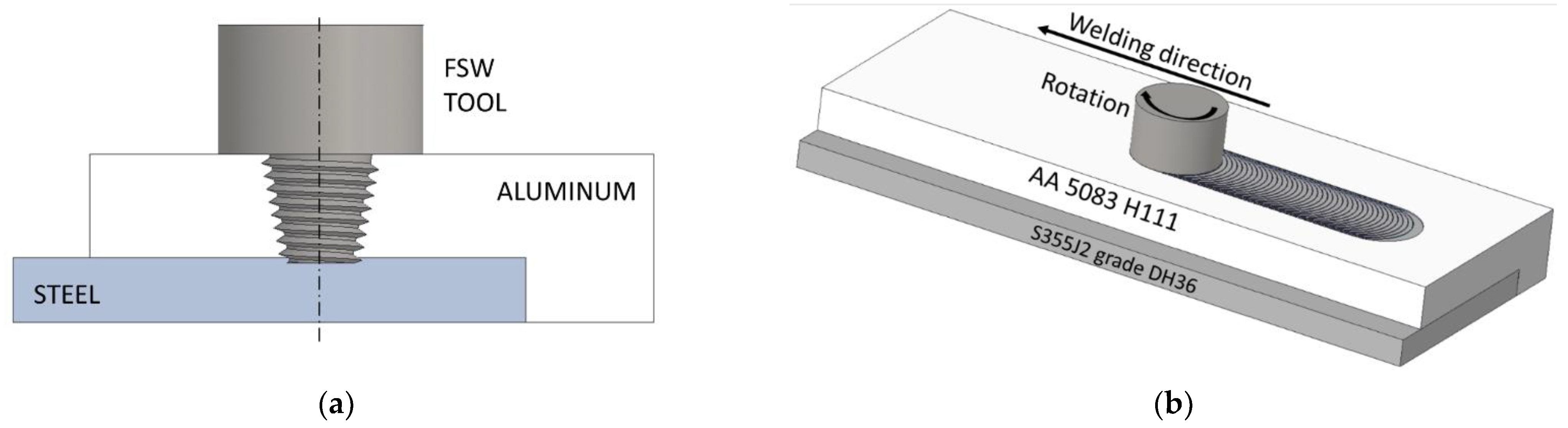
2.2. Methods
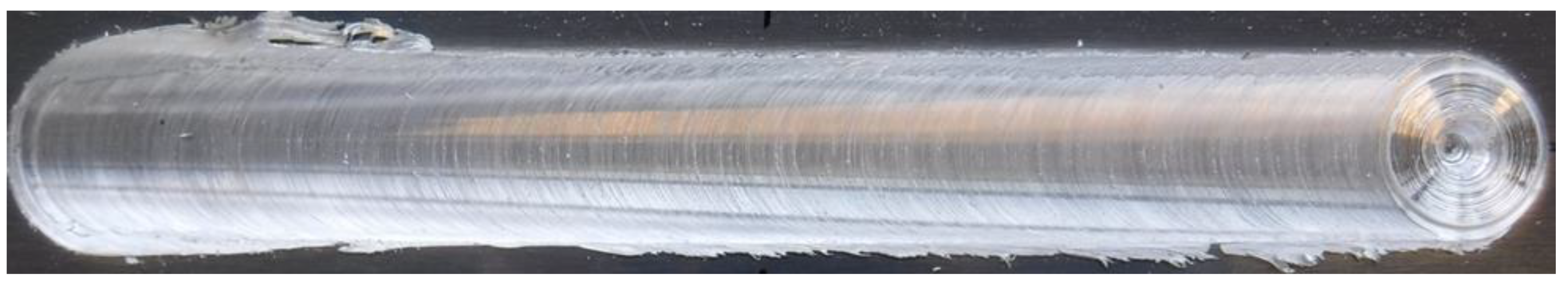
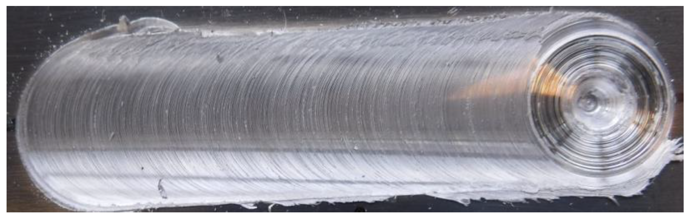
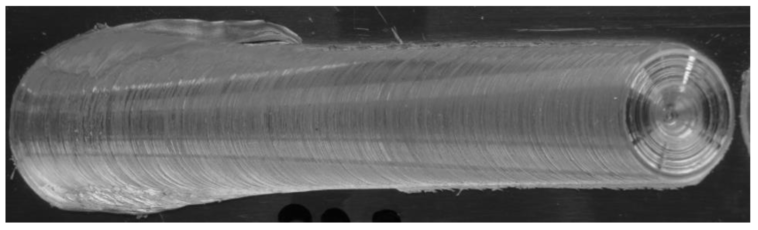
3. Results
4. Conclusions
Author Contributions
Funding
Data Availability Statement
Acknowledgments
Conflicts of Interest
References
- Bertram, M.; Buxmann, K.; Furrer, P. Analysis of greenhouse gas emissions related to aluminum transport applications. Int. J. Life Cycle Assess. 2009, 14, S62–S69. [Google Scholar] [CrossRef]
- Thomas, M.W.; Nicholas, E.D.; Needham, J.C.; Murch, M.G.; Temple-Smith, P.; Dawes, C.J. Friction Stir Butt Welding. International Patent No. 9,125,978.8, 6 December 1991. [Google Scholar]
- Kallee, S.W. Industrial applications of friction stir welding. In Friction Stir Welding From Basics to Applications; Woodhead Publishing: Sawston, UK, 2010; pp. 118–163. [Google Scholar]
- Casalino, G.; Campanelli, S.; Mortello, M. Influence of Shoulder Geometry and Coating of the Tool on the Friction Stir Welding of Aluminium Alloy Plates. Procedia Eng. 2014, 69, 1541–1548. [Google Scholar] [CrossRef] [Green Version]
- Zhou, L.; Yu, M.; Liu, B.; Zhang, Z.; Liu, S.; Song, X.; Zhao, H. Microstructure and mechanical properties of Al/steel dissimilar welds fabricated by friction surfacing assisted friction stir lap welding. J. Mater. Res. Technol. 2019, 9, 212–221. [Google Scholar] [CrossRef]
- Leonhardt, T.; Johnson, R. Processing and Properties of Tungsten Rhenium for Friction Stir Welding Application. In Proceedings of the Aeromat 20 Conference and Exposition American Society for Metals, Dayton, OH, USA, 7–11 June 2009. [Google Scholar]
- Sorensen, C.D.; Nelson, T.W. Progress in Polycrystalline Cubic Boron Nitride Friction Stir Welding Process. In Proceedings of the 4th International Friction Stir Welding Symposium, Park City, UT, USA, 14–16 May 2003. [Google Scholar]
- Sato, Y.S.; Miyake, M.; Imano, S.; Kokawa, H.; Omori, T.; Ishida, K.; Park, S.H.C.; Hirano, S. Development of a cobalt-based alloy fsw tool for high-softening-temperature materials. In Friction Stir Welding and Processing VI; Rajiv, S., Mishra, M.W., Yutaka, S., Yuri, H., Ravi, V., Eds.; Wiley: Hoboken, NJ, USA, 2011. [Google Scholar]
- Sato, Y.S.; Miyake, M.; Susukida, S.; Kokawa, H.; Omori, T.; Ishida, K.; Imano, S.; Park, S.H.C.; Sugimoto, I.; Hirano, S. Performance Enhancement of Co-Based Alloy Tool for Friction Stir Welding of Ferritic Steel. In Friction Stir Welding and Processing VIII; Springer: Cham, Switzerland, 2015; pp. 39–46. [Google Scholar] [CrossRef]
- Kumar, R.; Elango, V.; Giridharan, K.; Jothiprakash, V.; Stalin, B. Optimization and enhancement of friction stir welding strength on high yield strength deformed steel. Mater. Today Proc. 2020, 45, 1904–1907. [Google Scholar] [CrossRef]
- Hovanski, Y.; Santella, M.; Grant, G. Friction stir spot welding of hot-stamped boron steel. Scr. Mater. 2007, 57, 873–876. [Google Scholar] [CrossRef]
- Meinhardt, C.P.; Scheid, A.; Santos, J.F.d.; Bergmann, L.A.; Favaro, M.B.; Kwietniewski, C.E.F. Hydrogen embrittle-ment under cathodic protection of friction stir welded UNS S32760 super duplex stainless steel. Mater. Sci. Eng. A 2017, 706, 48–56. [Google Scholar] [CrossRef]
- Giorjão, R.A.R.; Pereira, V.F.; Terada, M.; da Fonseca, E.B.; Marinho, R.R.; Garcia, D.M.; Tschiptschin, A.P. Microstructure and mechanical properties of friction stir welded 8 mm pipe SAF 2507 super duplex stainless steel. J. Mater. Res. Technol. 2019, 8, 243–249. [Google Scholar] [CrossRef]
- Almoussawi, M.; Smith, A.J. Thermo-Mechanical Effect on Poly Crystalline Boron Nitride Tool Life during Friction Stir Welding (Dwell Period). Met. Mater. Int. 2018, 24, 560–575. [Google Scholar] [CrossRef] [Green Version]
- Sorensen, C.D.; Nelson, T.W. Friction stir welding of ferrous and nickel alloys. In Friction Stir Welding and Processing; Mishra, R.S., Mahoney, M.W., Eds.; ASM International: Materials Park, OH, USA, 2007; Volume 6, pp. 111–121. [Google Scholar]
- Dehghani, M.; Amadeh, A.; Mousavi, S.A.A.A. Investigations on the effects of friction stir welding parameters on intermetallic and defect formation in joining aluminum alloy to mild steel. Mater. Des. 2013, 49, 433–441. [Google Scholar] [CrossRef]
- Casalino, G.; Leo, P.; Mortello, M.; Perulli, P.; Varone, A. Effects of laser offset and hybrid welding on microstructure and IMC in Fe-Al dissimilar welding. Metals 2017, 7, 282. [Google Scholar] [CrossRef] [Green Version]
- Zhao, S.; Ni, J.; Wang, G.; Wang, Y.; Bi, Q.; Zhao, Y.; Liu, X. Effects of tool geometry on friction stir welding of AA6061 to TRIP steel. J. Mater. Process. Technol. 2018, 261, 39–49. [Google Scholar] [CrossRef]
- Forcellese, A.; Simoncini, M.; Casalino, G. Influence of process parameters on the vertical forces generated during friction stir welding of AA6082-T6 and on the mechanical properties of the joints. Metals 2017, 7, 350. [Google Scholar] [CrossRef] [Green Version]
- Elrefaey, A.; Gouda, M.; Takahashi, M.; Ikeuchi, K. Characterization of Aluminum/Steel Lap Joint by Friction Stir Welding. J. Mater. Eng. Perform. 2005, 14, 10–17. [Google Scholar] [CrossRef]
- Kimapong, K.; Watanabe, T. Lap Joint of A5083 Aluminum Alloy and SS400 Steel by Friction Stir Welding. Mater. Trans. 2005, 46, 835–841. [Google Scholar] [CrossRef] [Green Version]
- Chen, Z.W.; Yazdanian, S.; Littlefair, G. Effects of tool positioning on joint interface microstructure and fracture strength of friction stir lap Al-to-steel welds. J. Mater. Sci. 2013, 48, 2624–2634. [Google Scholar] [CrossRef]
- Huang, Y.; Wan, L.; Huang, T.; Meng, X.; Xie, Y. Achieving high-quality Al/steel joint with ultrastrong interface. Metall. Mater. Trans. A 2019, 50, 295–299. [Google Scholar] [CrossRef]
- Wang, T.; Sidhar, H.; Mishra, R.S.; Hovanski, Y.; Upadhyay, P.; Carlson, B. Evaluation of inter-metallic compound layer at aluminum/steel interface joined by friction stir scribe technology. Mater. Des. 2019, 174, 107795. [Google Scholar] [CrossRef]


| AA 5083 H111 | ||||||||||||
|---|---|---|---|---|---|---|---|---|---|---|---|---|
| Mg | Si | Fe | Cu | Mn | Cr | Zn | ||||||
| 4.0 ÷ 4.9 | 0.40 | 0.40 | 0.10 | 0.40−1.0 | 0.05–0.25 | 0.25 | ||||||
| S355J2 grade DH36 | ||||||||||||
| C max | Si max | S max | Al | Mn | Cr max | Ni max | P max | Ti max | Cu max | Mo max | Nb | V |
| 0.18 | 0.50 | 0.035 | 0.015 | 0.9–1.60 | 0.20 | 0.40 | 0.035 | 0.02 | 0.35 | 0.08 | 0.03 | 0.08 |
| 5083 H111 | ||
|---|---|---|
| Rm (MPa) | Rp0.2 (MPa) | A (%) |
| 275 | 125 | 16 |
| S355J2 grade DH36 | ||
| Rm (MPa) | Re min (MPa) | A (%) |
| 490 ÷ 630 | 350 | 21 |
| Samples (Original Batch) | Force (kN) | Travel Speed (mm/s) | Rotational Speed (rpm) | Weld Length (mm) |
|---|---|---|---|---|
| 953 | 20.75 | 1.3 | 800 | 230 |
| 954 | 21.25 | 1.3 | 800 | 230 |
| 957 | 21 | 1.7 | 800 | 230 |
| 958 | 21 | 1.7 | 1000 | 230 |
| 959 | 21 | 1.7 | 800 | 430 |
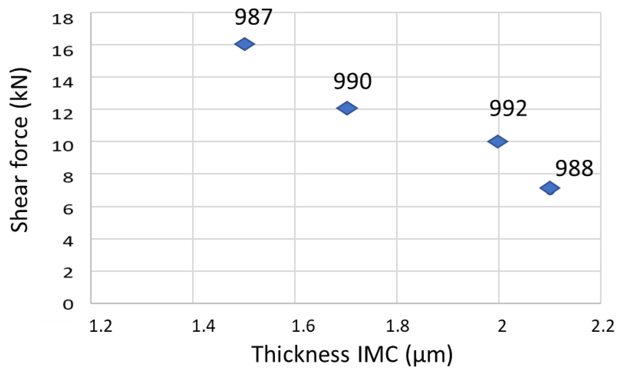
| 987 | 21 | 1.2 | 1000 | 430 |
| 988 | 21 | 1.9 | 900 | 430 |
| 990 | 21 | 2.1 | 700 | 430 |
| 992 | 21 | 1.2 | 900 | 430 |
| 993 | 24.5 | 1.2 | 1000 | 430 |
| 994 | 28.5 | 1.5 | 700 | 430 |
| 998 | 24.5 | 1.5 | 800 | 160 |
| 995 | 26.3 | 1.7 | 700 | 430 |
| 984 | 21 | 1.7 | 800 | 430 |
| 985 | 21 | 1.7 | 800 | 430 |
| 999 | 21 | 1.7 | 800 | 150 |
| 996 | 30 | 1.9 | 700 | 275 |
| 997 | 26.3 | 1.9 | 700 | 150 |
| 1000 | 27 | 1.9 | 800 | 145 |
| N° | Position | Fmax (kN) |
|---|---|---|
| 954 | A | 7 |
| B | 9 | |
| 957 | A | 13 |
| B | 15 | |
| 958 | A | 12 |
| B | 13 | |
| 959 | A | 12 |
| B | 15 | |
| 994 | A | 13 |
| B | 10 | |
| C | 12 | |
| D | 9 | |
| E | 7 | |
| F | 12 | |
| G | 15 | |
| H | 4 | |
| I | 5 | |
| J | 12 | |
| K | 11 | |
| 996 | A | 16 |
| B | 16 | |
| 998 | A | 10 |
| B | 16 | |
| C | 15 | |
| 999 | A | 5 |
| B | 11 | |
| C | 10 |
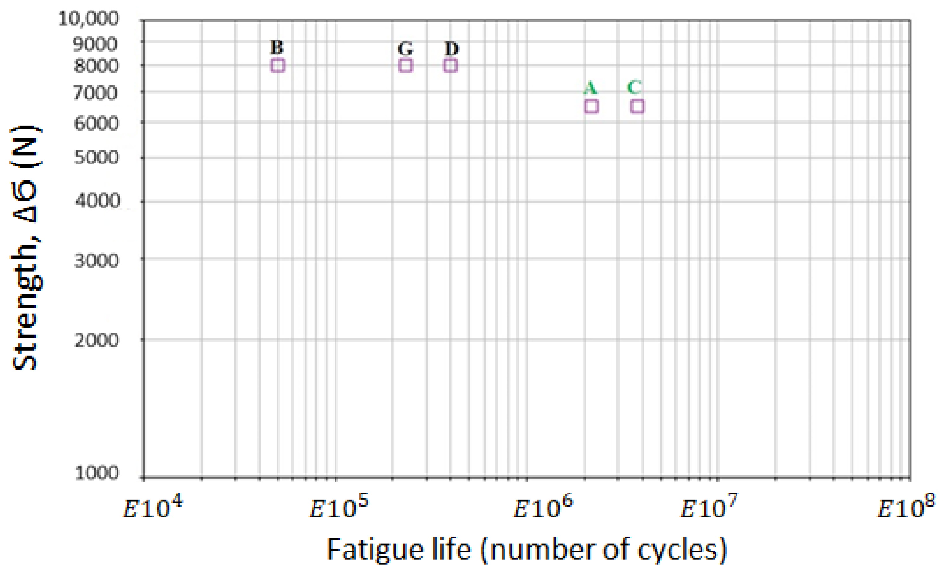
| Samples | σmax (N) | σmin (N) | σm (N) | Δσ/2 (N) | Δσ (N) | R | Number of Cycles at Break | Fracture Zone |
|---|---|---|---|---|---|---|---|---|
| A | 7750 | 1250 | 4500 | 3250 | 6500 | 0.16 | 2,084,900 | TMAZ steel |
| B | 8500 | 500 | 4500 | 4000 | 8000 | 0.06 | 49,814 | nugget |
| C | 7750 | 1250 | 4500 | 3250 | 6500 | 0.16 | 3,551,460 | TMAZ steel |
| D | 8500 | 500 | 4500 | 4000 | 8000 | 0.06 | 395,000 | nugget |
| G | 8500 | 500 | 4500 | 4000 | 8000 | 0.06 | 229,670 | nugget |
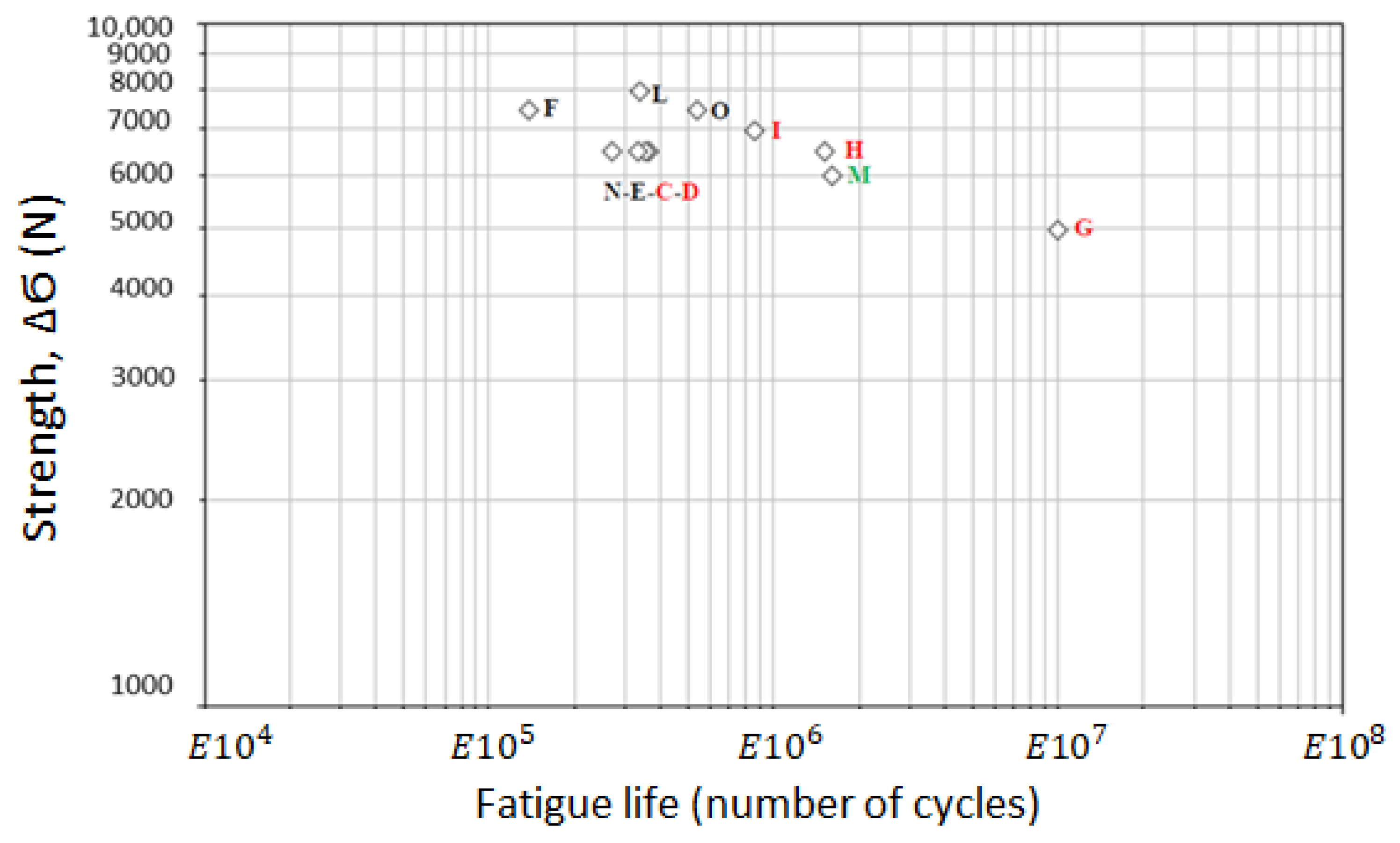
| Samples | σmax (N) | σmin (N) | σm (N) | Δσ/2 (N) | Δσ (N) | R | Number of Cycles at Break | Fracture Zone |
|---|---|---|---|---|---|---|---|---|
| C | 7750 | 1250 | 4500 | 3250 | 6500 | 0.16 | 339,710 | TMAZ aluminum |
| D | 7750 | 1250 | 4500 | 3250 | 6500 | 0.16 | 340,085 | TMAZ aluminum |
| E | 7750 | 1250 | 4500 | 3250 | 6500 | 0.16 | 330,360 | nugget |
| F | 8250 | 750 | 4500 | 3750 | 7500 | 0.09 | 136,590 | nugget |
| G | 7000 | 2000 | 4500 | 2500 | 5000 | 0.29 | 9,770,460 | TMAZ aluminum |
| H | 7750 | 1250 | 4500 | 3250 | 6500 | 0.16 | 1,451,030 | TMAZ aluminum |
| I | 8000 | 1000 | 4500 | 3500 | 7000 | 0.13 | 842,780 | TMAZ aluminum |
| L | 8500 | 500 | 4500 | 4000 | 8000 | 0.06 | 337,525 | nugget |
| M | 7500 | 1500 | 4500 | 3000 | 6000 | 0.20 | 1,535,770 | TMAZ steel |
| N | 7750 | 1250 | 4500 | 3250 | 6500 | 0.16 | 263,130 | nugget |
| O | 8250 | 750 | 4500 | 3750 | 7500 | 0.09 | 531,589 | nugget |
Publisher’s Note: MDPI stays neutral with regard to jurisdictional claims in published maps and institutional affiliations. |
© 2021 by the authors. Licensee MDPI, Basel, Switzerland. This article is an open access article distributed under the terms and conditions of the Creative Commons Attribution (CC BY) license (https://creativecommons.org/licenses/by/4.0/).
Share and Cite
Mortello, M.; Pedemonte, M.; Contuzzi, N.; Casalino, G. Experimental Investigation of Material Properties in FSW Dissimilar Aluminum-Steel Lap Joints. Metals 2021, 11, 1474. https://doi.org/10.3390/met11091474
Mortello M, Pedemonte M, Contuzzi N, Casalino G. Experimental Investigation of Material Properties in FSW Dissimilar Aluminum-Steel Lap Joints. Metals. 2021; 11(9):1474. https://doi.org/10.3390/met11091474
Chicago/Turabian StyleMortello, Michelangelo, Matteo Pedemonte, Nicola Contuzzi, and Giuseppe Casalino. 2021. "Experimental Investigation of Material Properties in FSW Dissimilar Aluminum-Steel Lap Joints" Metals 11, no. 9: 1474. https://doi.org/10.3390/met11091474
APA StyleMortello, M., Pedemonte, M., Contuzzi, N., & Casalino, G. (2021). Experimental Investigation of Material Properties in FSW Dissimilar Aluminum-Steel Lap Joints. Metals, 11(9), 1474. https://doi.org/10.3390/met11091474