Article

The Role of Retained Austenite in Tempered Martensite Embrittlement of 4340 and 300-M Steels Investigated through Rapid Tempering

1
Dynamic and Quasi-Static Loading Experimental Team, Los Alamos National Laboratory, P.O. Box 1663, Los Alamos, NM 87545, USA
2
Department of Physics, Colorado School of Mines, Golden, CO 80401, USA
3
George S. Ansell Department of Metallurgical and Materials Engineering, Colorado School of Mines, Golden, CO 80401, USA
*
Author to whom correspondence should be addressed.
Metals 2021, 11(9), 1349; https://doi.org/10.3390/met11091349
Submission received: 23 July 2021 / Revised: 10 August 2021 / Accepted: 24 August 2021 / Published: 27 August 2021
(This article belongs to the Special Issue Heat Treatment and Mechanical Properties of Metals and Alloys)

Abstract

:
Tempered martensite embrittlement (TME) is investigated in two medium carbon, high strength steels, 4340 (low silicon) and 300-M (high silicon), via rapid (1, 10, or 100 s) and conventional (3600 s) tempering. Rapid tempering of 4340 diminishes the depth of the TME toughness trough, where improvements in impact toughness correspond to the suppression of retained austenite decomposition. In 300-M, retained austenite decomposition is suppressed to an even greater extent by rapid tempering. While toughness improves overall after rapid tempering, TME severity remains consistent in 300-M across the tempering conditions examined. Through interrupted tensile tests, it was found that the 300-M conditions that exhibit TME are associated with mechanically unstable retained austenite. Unstable retained austenite is shown to mechanically transform early in the deformation process, presumably resulting in fresh martensite adjacent to interlath cementite that ultimately contributes to TME. The present results emphasize the role of both the thermal decomposition and mechanical transformation of retained austenite in the manifestation of TME.

1. Introduction

Tempered martensite embrittlement (TME) is a phenomenon characterized by a reduction in the room temperature toughness of steels tempered within the regime associated with retained austenite decomposition [1]. The embrittlement associated with TME limits the strength–toughness properties achievable in medium carbon, high strength steels such as AISI 4340. However, rapid tempering on the scale of seconds has recently been shown to reduce TME in 4340 steel, leading to significantly improved strength-toughness combinations [2,3,4,5]. In addition to suppressing TME, rapid tempering is associated with a greater preservation of retained austenite upon tempering compared to more conventional treatments [2,3,6].
Tempering is associated with specific microstructural changes that are often separated into three stages [1,7]. The first stage of tempering (100–250 °C) involves the formation of transition carbides from supersaturated martensite. At higher temperatures (200–300 °C), retained austenite decomposes to ferrite and cementite in what is known as stage two tempering. Finally, stage three (250–350 °C) tempering entails the replacement of low-carbon martensite and transitions carbides with ferrite and cementite. In addition to a distinct microstructural evolution, tempering is commonly associated with specific changes in mechanical properties [8,9]. With increased tempering (higher temperatures and longer times), toughness and ductility typically increase while strength and hardness are reduced. However, TME represents a regime in which increased tempering results in a reduction in toughness, even while hardness and strength decrease. TME is associated with several proposed mechanisms within the literature, including retained austenite decomposition to ferrite and cementite, cementite coarsening, and the mechanical transformation of retained austenite to fresh martensite. Many [10,11,12,13,14] attribute TME to retained austenite decomposition into interlath cementite (and ferrite) during tempering, where cementite then acts as an embrittling agent by providing preferred crack initiation sites and propagation pathways. Others [15,16,17] emphasize the role of inter- and/or intra-lath cementite coarsening, in which precipitates are assumed to reach some critical particle size such that fracture is promoted. Horn and Ritchie [11] proposed that both the thermal decomposition and mechanical transformation of retained austenite contribute to TME, as the transformation of interlath retained austenite to cementite or fresh martensite both result in the presence of a brittle constituent at lath boundaries. Although not studying TME specifically, Tomita and Okawa [18] also attributed brittle behavior in a 300-M alloy to the mechanical transformation of unstable retained austenite during deformation.
Previous studies [2,3,4] relate the improvement in toughness associated with rapid tempering of 4340 to the greater retention of austenite during tempering. Recently, the combined influence of silicon alloying and rapid tempering on retained austenite decomposition was explored by rapidly tempering 300-M, a high-silicon version of 4340 [6]. Silicon delays the decomposition of retained austenite to higher temperatures and/or longer times [19,20], thus affecting TME behavior [11]. A significant increase in retained austenite preservation was observed via the rapid tempering of 300-M compared to rapidly tempered 4340 and conventionally tempered conditions. Given the proposed theory that TME is diminished in rapidly tempered 4340 due to the enhanced preservation of retained austenite during tempering, rapidly tempered 300-M may offer an even greater improvement in toughness performance within the TME regime. Here, the properties associated with rapidly and conventionally tempered 4340 and 300-M are compared to investigate the role of retained austenite in the manifestation of TME in these alloys.

2. Materials and Methods

The chemical compositions of the 4340 and 300-M alloys used in the current study are displayed in Table 1. Carbon content is indicated for each alloy, displaying both the concentrations reported by the manufacturer and the values measured by the authors using LECO combustion analysis (footnote). The 4340 alloy was received in the form of a 12.7 mm (0.5 in) plate in the annealed condition. The 300-M material was received as two 22.2 × 15.2 cm (8.75 × 6 in) cylindrical billets in the hot-rolled condition. Prior to heat treatment, the material was machined into longitudinal Charpy and tensile blanks for easier processing. Charpy and tensile blanks were machined from the original 300-M billet at a consistent radial position. All specimens were austenitized at 845 °C (4340) or 870 °C (300-M) for 1 h and were quenched into room temperature, agitated oil. Austenitizing temperatures were chosen to produce a similar expected grain size and to adhere to recommended industrial heat treatment practices [21]. Conventional (3600 s) tempers were performed in a nitrate salt bath (4340) or box furnace (300-M) followed by water quenching. Rapid (1, 10, and 100 s) tempering was executed using a Gleeble® 3500 (Dynamic Systems Inc., Poestenkill, NY, USA) where a heating rate of 420–1000 °C/s was achieved, followed by quenching with helium. See [4,22] for a detailed account of the rapid tempering procedures.
Tempering times of 1, 10, 100, and 3600 s were chosen to represent conventional (3600 s) and rapid (1, 10, 100 s) tempering treatments. Conventional time–temperature combinations were chosen to coincide with the TME regime of each alloy, and rapid tempering treatments were subsequently designed using the conventional treatments as a baseline. The temperature regimes associated with TME in 4340 and 300-M are relatively well documented within the literature [10,11]. TME typically manifests after tempering between 200 and 400 °C in 4340, while a higher temperature regime of 350 to 500 °C is associated with TME in 300-M. Thus, these temperature ranges were chosen for the conventional tempering treatments of the two steels, as shown in Table 2. Rapid (short time) treatments were selected such that the rapid and conventional conditions produced an equivalent tempered hardness, with the intent of applying an “equivalent degree” of tempering. A time–temperature–hardness study was conducted to determine time–temperature combinations that would produce hardness values similar to the base 3600 s conditions of 4340 and 300-M. Table 2 displays the utilized time–temperature combinations, where for a given alloy, each column corresponds to an “equivalent” temper. The range of average hardness values across all time conditions is shown for each column of equivalent time-temperature combinations. As indicated, there is only a small variation in the achieved hardness across the tempering times for a given “equivalent” hardness. The results of the present study are represented as a function of the measured hardness to account for any mechanical or microstructural changes related to the slight variations in tempered hardness.
Uniaxial tensile testing was conducted using a 10 mm extensometer to measure displacement at an engineering strain rate of 0.015 mm/mm/min. Ultimate tensile strength (UTS) was taken to be the highest stress value, while yield strength (YS) was calculated using the 0.2% offset method. Room temperature Charpy V-notch testing was conducted in accordance with ASTM E23 [23]. Samples were taken in the longitudinal-transverse orientation with respect to the original 4340 plate. For 300-M samples, the Charpy specimen V-notch was machined on the face of the blank closest to the outer diameter of the billet. Microhardness measurements were conducted using an automatic LECO AMH55 (300-M) (LECO, St. Joseph, MO, USA) and a manual LECO MHT200 (4340) (LECO, St. Joseph, MO, USA) micro-indentation hardness tester with a 500 g-f load and a 10 s dwell time. Samples were prepared via mounting and polishing to a 1 µm finish. A minimum of 1 mm of the exposed surface was removed in order to eliminate any effects of decarburization.
Mössbauer spectroscopy samples were prepared via mechanical grinding to a thickness of approximately 80 μm. Subsequent thinning was performed using a solution of 10 parts deionized water, 10 parts hydrogen peroxide, and 1 part hydrofluoric acid to achieve a final thickness between 15 and 40 μ m. The Mössbauer experiments have been described in further detail elsewhere [3,6]. Each Mössbauer spectrum was fit with multiple sub-spectra associated with resonance from martensite/ferrite ( α ), retained austenite ( γ R ), cementite ( θ ), and transition carbides ( η ) by optimizing the χ 2 -fitting parameter. Following appropriate fitting of the overall spectrum with sub-spectra representing α , γ , η , and θ , the resonance area values for each constituent were converted to Fe atomic fractions. This conversion was achieved by first applying a thickness correction consistent with the methodology outlined by Pierce et al. [24] followed by recoilless fraction corrections based on the fraction of Fe sites associated with the effective thickness and recoilless fractions of α , γ , η , [24] and θ [25], respectively. While the α , γ , η , and θ phases were all quantified with Mössbauer spectroscopy, only the retained austenite and cementite results are presented here. Further details regarding the fitting process, calculation of the phase fractions, and error analysis associated with the Mössbauer spectroscopy data are presented in previous studies [3,6]. Results determined via Mössbauer spectroscopy are presented in terms of atomic percent iron since these are the numbers that come directly from the Mössbauer analysis. The volume per iron atom is similar in martensite/ferrite and austenite, only varying by 0 pct up to 3 pct depending on the carbon in solution in the two phases [26]. Therefore, the atomic percent iron results presented here do not vary much from the more conventional unit of volume percent.
The carbon concentration in the retained austenite was calculated from the fraction of the Fe sites in the retained austenite without the carbon nearest neighbors:
r ( 0 ) = ( 1 X C 1 X C ) 6
where XC is the atomic fraction of carbon in austenite, and r ( 0 ) is the Fe fraction associated with the central resonance of the austenite Mössbauer spectrum [24,27,28]. The carbon concentration could not be reliably quantified for conditions with an austenite content below ~0.5 at. pct Fe; thus, an indicated carbon content of 0 signifies an associated austenite amount below the 0.5 at. pct threshold.
X-ray diffraction (XRD) specimens were prepared from tensile samples by sectioning and lightly grinding the appropriate face with a progression of 250, 320, 400, and 600 grit metallographic paper. Samples were subsequently thinned in a solution of 10 parts deionized water, 10 parts hydrogen peroxide, and 1 part hydrofluoric acid to achieve a thickness reduction of at least 0.005 in (0.127 mm) as per ASTM standard E975 [29]. Retained austenite volume fractions were determined using graphite monochromated copper radiation and a Siemens D500 diffractometer with the operating conditions of 30 kV and 25 mA. The Siemens diffractometer was instrumented with a scintillation detector and 1° slit. The samples were scanned over a 2θ range from 40 to 105°, with a step size of 0.02° and an 18 s dwell time. The sample was continuously rotated during data collection to mitigate texture effects. A total of four ferrite/martensite peaks ({110}, {200}, {211}, {220}) and four austenite peaks ({111}, {200}, {220}, {311}) were compared to determine the amount of retained austenite. The peaks were fit using a Voigt profile (mixture of Gaussian and Lorentzian distributions). The full-width-half-max and height of the identified peaks were used to quantify the intensity of each peak. Retained austenite percentages were calculated in accordance with the SAE method [30].

3. Results

3.1. Tensile Properties

Yield (σ0.2) and ultimate tensile (σUTS) strength results are displayed in Figure 1 as a function of hardness. Consistent σ0.2 values are largely observed across tempering time conditions for a given alloy, with greater differences at lower hardness values. The yield strength behavior varies significantly when comparing 4340 and 300-M within a consistent hardness regime. At high hardness values, yield strength reductions with tempering are smaller in the 4340 alloy, whereas 300-M exhibits a greater decrease in yield strength with decreasing hardness, albeit from a higher initial value. Above ~580 HV, 300-M shows significantly higher yield stress values compared to 4340, and lower values below ~580 HV. The microstructural mechanisms that contribute to the varied yield strength between 300-M and 4340 at a given hardness are not presently understood, although it is interesting to note. For both alloys, hardness and σUTS follow a linear relationship. Ultimate tensile strength values are relatively consistent across 4340 and 300-M at a given hardness, although there is a slightly reduced strength associated with 300-M. The 4340 strength results were previously presented in [3] as a function of the Hollomon–Jaffe tempering parameter. The 4340 results were previously presented as a function of the tempering parameter in [3] and showed that shorter tempering times exhibited systematically lower tensile strengths compared to longer tempering times. This behavior is now thought to be a result of slight differences in hardness at a given tempering parameter.

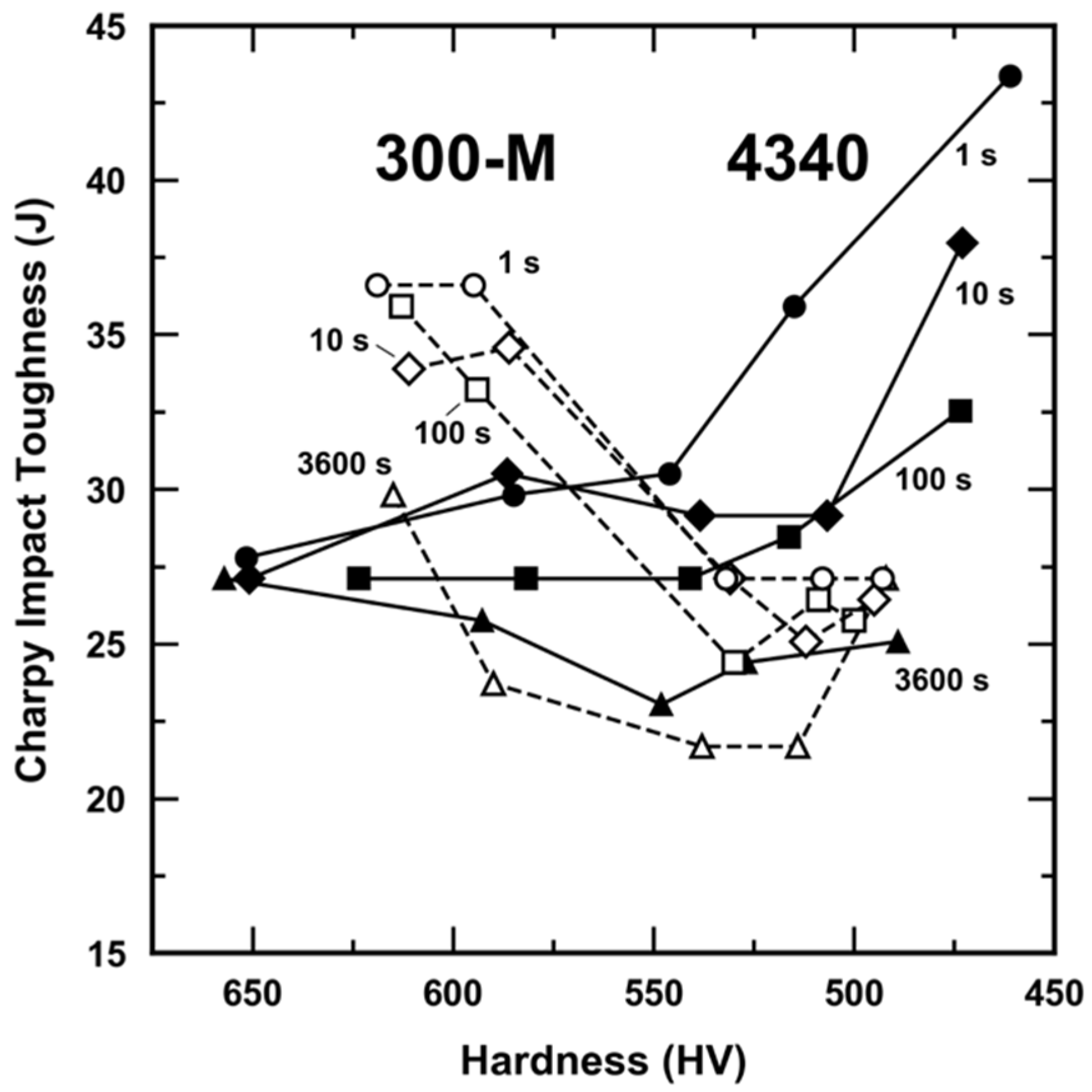
3.2. Room Temperature Impact Toughness

The 4340 and 300-M impact toughness results are compared in Figure 2 as a function of tempered hardness, where decreasing hardness reflects a greater degree of tempering. Both alloys exhibit a differentiation in toughness with respect to tempering time, where shorter tempering times are associated with an improvement in impact toughness. A noticeable difference in the relationship between tempering time and TME severity is observed between 4340 and 300-M. TME severity is related to the magnitude of the observed decrease in toughness, where more severe TME is associated with a greater reduction in toughness as a function of tempering. The TME severity decreases with decreasing tempering time in 4340, where shorter tempering times exhibit smaller or non-existent reductions in toughness with increased tempering (decreased hardness). In contrast, 300-M does not exhibit a clear relationship between tempering time and TME severity since a similar toughness reduction is present for all of the 300-M tempering conditions that were examined. Quasi-cleavage fracture was observed in both alloys within the TME regime; however, a greater prevalence of ductile features was associated with shorter tempering times (see [4] for quantitative analysis of 4340).

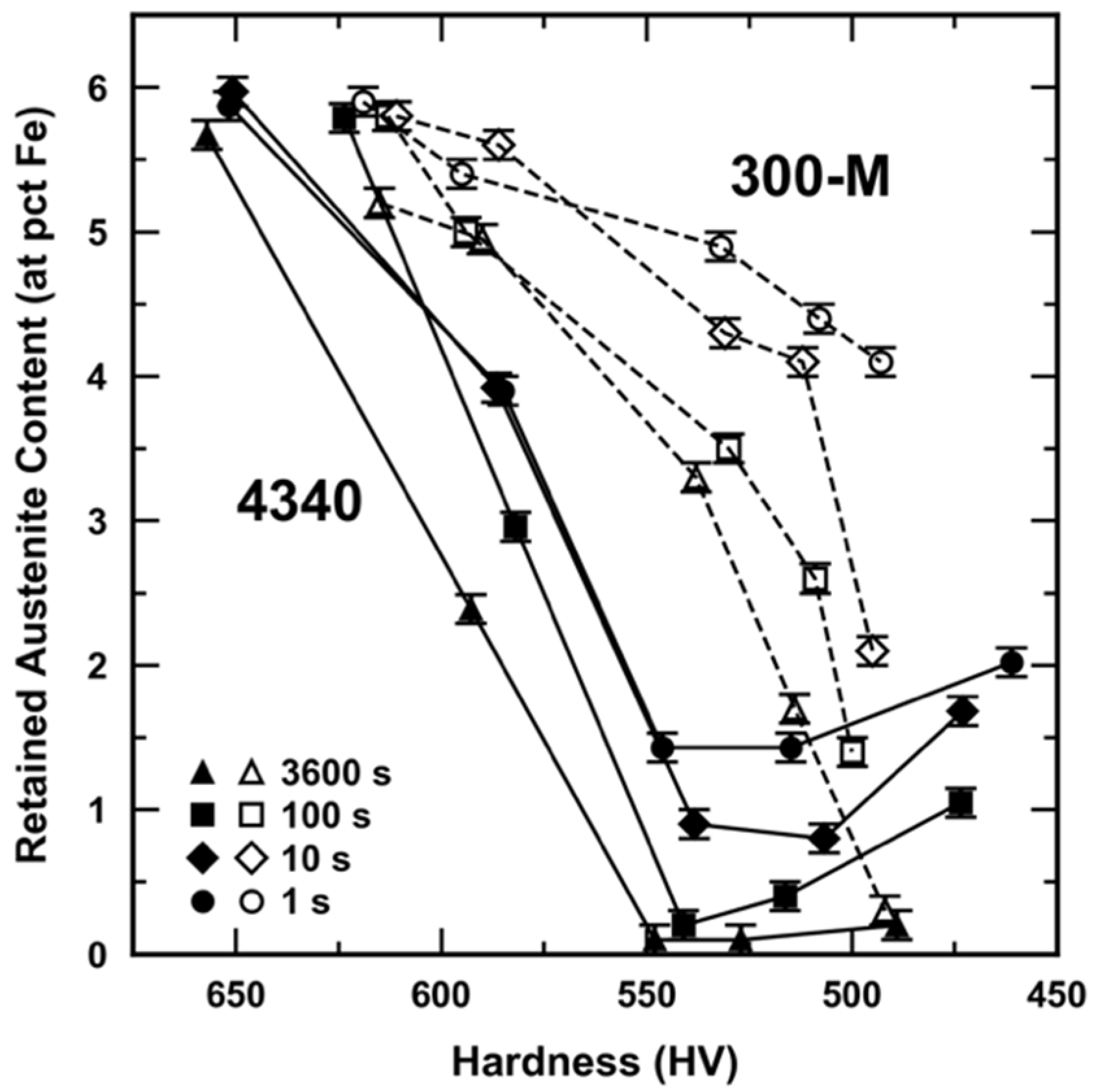
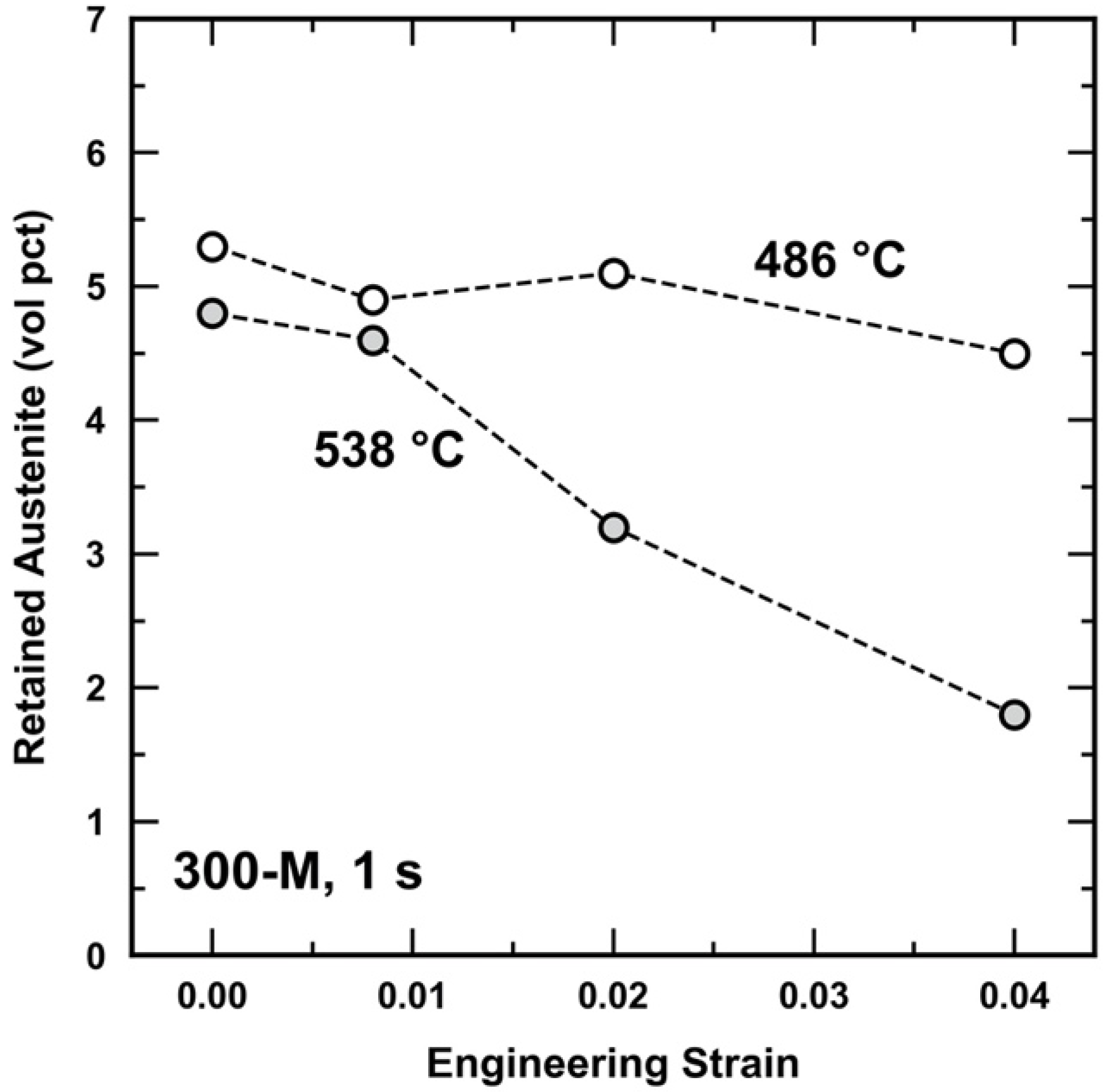
3.3. Retained Austenite

Mössbauer spectroscopy was utilized to quantify the retained austenite phase fraction for all of the 4340 and 300-M tempering conditions. Figure 3 displays retained austenite content as a function of tempered hardness for all of the time conditions of 4340 and 300-M. Retained austenite decomposition occurs to different degrees with increased tempering (lower hardness) for all conditions. Shorter tempering times (associated with higher temperatures) are shown to suppress retained austenite decomposition in both 4340 and 300-M. Overall, 300-M exhibits greater amounts of retained austenite compared to 4340 at an equivalent hardness. The greater preservation of retained austenite in 300-M is attributed to silicon’s suppression of retained austenite decomposition. An in-depth discussion of the combined influence of rapid tempering and silicon on microstructural evolution upon tempering is covered elsewhere [6].
Figure 4 displays the carbon concentration of retained austenite as a function of tempered hardness for all 300-M and 4340 tempering conditions. The carbon concentration of the as-quenched (AQ) conditions of 4340 and 300-M is consistent with the bulk carbon content of both alloys (LECO value). Initial tempering leads to the carbon enrichment of the retained austenite in both the 4340 and 300-M alloys, although to different degrees. A carbon concentration of ~1.2 wt pct is reached in 300-M, while 4340 only enriches to ~0.8 wt pct within the same hardness regime (~600–620 HV). With further tempering (<600 HV), 300-M exhibits a marked decrease in retained austenite carbon concentration from ~1.2 to ~0.4 wt pct, while 4340 has a relatively constant carbon content of ~0.6–0.85 wt pct. A previous study [6] showed that the retained austenite carbon enrichment in 300-M coincides with the regime in which retained austenite decomposition and cementite precipitation are suppressed, whereas the depletion of carbon in retained austenite aligns with significant cementite precipitation and retained austenite decomposition. Thus, retained austenite decomposition involving the incorporation of carbon into newly forming cementite is believed to drive the depletion of carbon in the retained austenite of 300-M. In contrast, the 4340 retained austenite carbon concentration remains consistent throughout retained austenite decomposition and tempering as a whole. This behavior is not as well understood and requires further investigation.

4. Discussion

TME severity is thought to be reduced in 4340 with more rapid tempering (at an equivalent degree of tempering) via the suppression of retained austenite decomposition, whereby less interlath cementite is available to act as an embrittling agent. This theory has been discussed in previous studies [2,3,6] and is supported by the often observed connection between retained austenite decomposition and TME [10,11,12,13,14]. Thus, it might be expected that a greater preservation of retained austenite during tempering should always diminish embrittlement associated with TME. However, this behavior is not observed in 300-M, as illustrated in Figure 5. Figure 5 shows the maximum decrease in toughness (absorbed energy at 25 °C) associated with all of the time conditions of 300-M and 4340, where a larger decrease in absorbed energy is associated with more distinctive TME behavior. The maximum decrease in toughness refers to the difference in absorbed energy between the condition prior to the appearance of TME with the highest toughness and the condition within the TME trough with the lowest toughness. Here, the appearance of TME is associated with an observed decrease (or plateau) in toughness with increasing tempering (decreasing hardness). The percent of retained austenite decomposed between the maximum and minimum toughness conditions is also displayed for each tempering time. For example, in the 3600 s condition of 4340, 98 percent of the retained austenite present in the maximum toughness condition has decomposed in the minimum toughness condition. The conventional 4340 condition exhibits moderate TME severity, with a maximum decrease in absorbed energy of 4 J. As tempering time decreases (within an equivalent tempered hardness regime), retained austenite decomposition is suppressed and TME severity diminishes. Compared to 4340, the conventional tempering condition of 300-M is associated with a more severe, deeper TME trough, with a maximum decrease in absorbed energy of ~12 J. Moreover, 300-M exhibits even more retained austenite preservation with rapid tempering yet no accompanying diminishment of the TME trough. Therefore, retained austenite is thought to play different roles in the manifestation of TME in 4340 and 300-M in the present work.
In a previous study that focused on the TME behavior of 4340 and 300-M, Horn and Ritchie suggested that TME severity is controlled by both the thermal decomposition and mechanical transformation of retained austenite [11]. During deformation/fracture, the retained austenite remaining within the microstructure may mechanically transform to fresh martensite due to mechanical instability. The newly transformed martensite, adjacent to the existing cementite films, may then augment any existing embrittlement. Therefore, according to Horn and Ritchie’s hypothesis, TME is primarily dependent on the formation of interlath cementite during the second stage of tempering and may be exacerbated by the mechanical transformation of retained austenite during deformation. Given the relatively high retained austenite contents remaining after rapid tempering of 300-M and the distinctive appearance of TME, it may be that TME is associated with both the thermal and mechanical transformation of retained austenite in the 300-M conditions of the present study. If TME is controlled by the thermal and mechanical transformation of retained austenite, conditions that do and do not exhibit TME should show a marked difference in the retained austenite content and/or the carbon concentration (stability) of the retained austenite.
Figure 6 displays the retained austenite carbon concentration and impact energy as a function of temperature for the 300-M in the 1 s tempering condition. A marked decrease in toughness (representing TME) is observed between the 486 and 538 °C tempering conditions. This clear decrease in toughness is accompanied by a significant decrease in retained austenite carbon concentration, while the retained austenite fraction remains nearly unchanged. The 300-M alloy exhibits a marked decrease in retained austenite stability in conjunction with the appearance of TME, as interpreted by the decrease in carbon concentration, while 4340 does not show a similar relationship due to the consistency of Cγ across its tempering conditions. Rather, the appearance of TME in 4340 is more strongly connected to a large reduction in the retained austenite amount.
While a lower retained austenite carbon concentration is typically associated with lower mechanical stability, other factors, such as austenite morphology and size and surrounding matrix properties, can also affect austenite stability [31,32]. Therefore, interrupted tensile tests were performed on the 1 s-486 and 1 s-538 °C treatments to directly evaluate the mechanical stability of the retained austenite and to test the proposed hypothesis. Based on the carbon content results in Figure 6, it was expected that retained austenite associated with the 538 °C condition would be significantly less stable than the 486 °C condition. A total of three strain levels (0.008, 0.02, 0.04) were chosen to evaluate the degree of retained austenite transformation. The 0.008 strain condition is within the elastic regime, while both the 0.02 and 0.04 strains correspond to plastic deformation. Separate samples were used for each strain condition.
Figure 7 shows retained austenite content as a function of engineering strain for the 486 and 538 °C tempering conditions. As strain increases, there is a general decrease in the retained austenite content for both tempering treatments although the response is much greater for the 538 °C condition. At 4 pct strain, 63 pct of the retained austenite has transformed in the 538 °C condition, compared to only 15 pct in the 486 °C condition. These results confirm that there is a significant difference in the mechanical stability of the retained austenite in the 1 s-486 °C and 1 s-538 °C conditions of 300-M, where the observed decrease in the mechanical stability of the retained austenite coincides with the appearance of TME. The mechanical transformation of retained austenite to fresh martensite during deformation is thus believed to play a role in the severity of TME in 300-M, as first suggested by Horn and Ritchie [11].
Tempered martensite embrittlement in both 4340 and 300-M is proposed to involve the formation of a constituent on lath boundaries that promotes brittle fracture. In 4340, this constituent is believed to be primarily cementite formed from the decomposition of the interlath retained austenite during tempering. The suppression of retained austenite decomposition via rapid tempering thus diminishes the severity of TME. In 300-M, interlath cementite precipitation occurs during tempering and contributes to embrittlement, much like 4340. In addition, the transformation of the unstable retained austenite to fresh martensite early in the deformation process is believed to contribute to TME in 300-M. Therefore, while the preservation of the retained austenite is critical in avoiding TME, the stability of the remaining austenite is also important. Table 3 summarizes the proposed microstructural contributions (it is noted that there may be other, unexplored contributions to the embrittlement behavior. One such area of interest is the effect of phosphorus segregation to boundaries during tempering [33]. Since impurity segregation decreases boundary surface energy [34], it is believed that the phosphorus segregation to the ferrite–cementite boundaries may lead to a higher susceptibility to brittle fracture at these interfaces. Due to the higher temperature regime associated with 300-M, ferrite–cementite boundaries and interfaces during tempering compared to 4340. It would be of further interest to understand how and if the different time/temperature regimes associated with 300-M and 4340 in this study may affect phosphorus segregation and ultimately the embrittlement) that lead to TME in 300-M and 4340 considering both rapid and conventional tempering conditions.

5. Conclusions

The toughness trough associated with TME is reduced through rapid tempering of 4340, where improvements in impact toughness with shorter tempering times (at an equivalent hardness) are linked to the suppression of retained austenite decomposition into interlath cementite. Retained austenite decomposition is suppressed to an even greater extent through the rapid tempering of 300-M. While toughness increases overall, the TME toughness trough is not diminished by rapid tempering in this alloy. Through interrupted tensile tests, it was determined that 300-M conditions that exhibit TME are associated with mechanically unstable retained austenite due to low carbon concentration. During mechanical deformation, it is presumed that unstable retained austenite mechanically transforms early in the deformation process, resulting in fresh martensite adjacent to interlath cementite. Thus, due to the low stability of the remaining austenite, rapid tempering does not reduce TME in 300-M; however, a general improvement in impact energy is still observed with more rapid tempering. In order to effectively suppress TME, the prevention of both thermal and mechanical retained austenite decomposition is important.

Author Contributions

Conceptualization: J.G.S., A.J.C. and V.K.E.; investigation: V.K.E. and D.L.W.; supervision: J.G.S., A.J.C. and K.O.F., writing—original draft Preparation: V.K.E.; writing—review and editing: J.G.S., A.J.C., D.L.W., K.O.F. and V.K.E. All authors have read and agreed to the published version of the manuscript.

Funding

This research was funded by the sponsors of the Advanced Steel Processing and Products Research Center at the Colorado School of Mines.

Institutional Review Board Statement

Not applicable.

Informed Consent Statement

Not applicable.

Data Availability Statement

Data is contained within the article.

Acknowledgments

The authors gratefully acknowledge the financial and technical support of sponsors of the Advanced Steel Processing and Products Research Center (ASPPRC) at the Colorado School of Mines. The authors also thank the Los Alamos National Laboratory (LANL) and TimkenSteel for supplying the 4340 and 300-M steels, respectively.

Conflicts of Interest

The authors declare that there are no conflict of interest.

References

  1. Krauss, G. Steels: Processing, Structure, and Performance, 1st ed.; ASM International: Materials Park, OH, USA, 2015. [Google Scholar]
  2. Judge, V.K.; Speer, J.G.; Clarke, K.D.; Findley, K.O.; Clarke, A.J. Rapid Thermal Processing to Enhance Steel Toughness. Sci. Rep. 2018, 8, 445. [Google Scholar] [CrossRef] [Green Version]
  3. Euser, V.K.; Williamson, D.L.; Clarke, K.D.; Findley, K.O.; Speer, J.G.; Clarke, A.J. Effects of Short-Time Tempering on Impact Toughness, Strength, and Phase Evolution of 4340 Steel Within the Tempered Martensite Embrittlement Regime. Metall. Mater. Trans. A 2019, 50, 3654–3662. [Google Scholar] [CrossRef]
  4. Euser, V.K.; Clarke, A.J.; Speer, J.G. Rapid Tempering: Opportunities and Challenges. J. Mater. Eng. Perform. 2020, 29, 4155–4161. [Google Scholar] [CrossRef]
  5. Clarke, A.J. Perspectives on Quenching and Tempering 4340 Steel. Metall. Mater. Trans. A 2020, 22, 4984–5005. [Google Scholar] [CrossRef]
  6. Euser, V.K.; Williamson, D.L.; Clarke, A.J.; Speer, J.G. Limiting Retained Austenite Decomposition in Quenched and Tempered Steels: Influences of Rapid Tempering and Silicon. ISIJ Int. 2020, 60, 2990–3000. [Google Scholar] [CrossRef]
  7. Speich, G.R.; Leslie, W.C. Tempering of Steel. Metall. Trans. 1972, 13, 1043–1054. [Google Scholar] [CrossRef]
  8. Grange, R.A.; Baughman, R.W. Hardness of Tempered Martensite in Carbon and Low Alloy Steels. Trans. ASM 1956, 48, 165–197. [Google Scholar] [CrossRef]
  9. Saeglitz, M.; Krauss, G. Deformation, Fracture, and Mechanical Properties of Low-Temperature-Tempered Martensite in SAE 43xx Steels. Metall. Mater. Trans. A 1997, 28, 377–387. [Google Scholar] [CrossRef]
  10. Materkowski, J.P.; Krauss, G. Tempered Martensite Embrittlement in SAE 4340 Steel. Metall. Trans. A 1979, 10, 1643–1651. [Google Scholar] [CrossRef]
  11. Horn, R.M.; Ritchie, R.O. Mechanisms of Tempered Martensite Embrittlement in Low Alloy Steels. Metall. Trans. A 1978, 9, 1039–1053. [Google Scholar] [CrossRef]
  12. Thomas, G. Retained Austenite and Tempered Martensite Embrittlement. Metall. Trans. A 1978, 9A, 439–450. [Google Scholar] [CrossRef]
  13. Kwon, H.; Kim, C.H. Tempered Martensite Embrittlement in Fe-Mo-C and Fe-W-C Steel. Metall. Trans. A 1983, 14, 1389–1394. [Google Scholar] [CrossRef]
  14. Sarikaya, M.; Jhingan, A.K.; Thomas, G. Retained Austenite and Tempered Martensite Embrittlement in Medium Carbon Steels. Metall. Mater. Trans. A 1983, 14, 1121–1133. [Google Scholar] [CrossRef] [Green Version]
  15. King, J.E.; Smith, R.F.; Knott, J.F. Toughness Variations during the Tempering of a Plain Carbon Martensitic Steel. In Proceedings of the 4th International Conference on Fracture, Waterloo, ON, Canada, 19–24 June 1977; pp. 279–286. [Google Scholar]
  16. Bhadeshia, H.K.D.H.; Edmonds, D.V. Tempered Martensite Embrittlement: Role of Retained Austenite and Cementite. Met. Sci. 1979, 13, 325–334. [Google Scholar]
  17. Peters, J.A.; Bee, J.V.; Kolk, B.; Garrett, G.G. On the Mechanisms of Tempered Martensite Embrittlement. Acta Metall. 1989, 37, 675–686. [Google Scholar] [CrossRef]
  18. Tomita, Y.; Okawa, T. Effect of Microstructure on Mechanical Properties of Isothermally Bainite-Transformed 300M Steel. Mater. Sci. Eng. A 1993, 172, 145–151. [Google Scholar] [CrossRef]
  19. Allten, A.G.; Payson, P. The Effect of Silicon on the Tempering of Martensite. Trans. Am. Soc. Met. 1953, 45, 498. [Google Scholar]
  20. Owen, W.S. The Effect of Silicon on the Kinetics of Tempering. Trans. Am. Soc. Met. 1954, 46, 812–829. [Google Scholar]
  21. ASM International. Heat Treater’s Guide: Practices and Procedures for Irons and Steels, 2nd ed.; Chandler, H., Ed.; ASM International: Materials Park, OH, USA, 1996. [Google Scholar]
  22. Euser, V.K. The Effect of Rapid Tempering on Microstructural Evolution and Toughness within the Tempered Martensite Embrittlement Regime of 4340 and 300-M. Ph.D. Thesis, Colorado School of Mines, Golden, CO, USA, 2020. [Google Scholar]
  23. ASTM International. Standard Methods for Notched Bar Impact Testing of Metallic Materials E23; ASTM International: West Conshohocken, PA, USA, 1982; Volume 552. [Google Scholar]
  24. Pierce, D.T.; Coughlin, D.R.; Williamson, D.L.; Clarke, K.D.; Clarke, A.J.; Speer, J.G.; De Moor, E. Characterization of Transition Carbides in Quench and Partitioned Steel Microstructures by Mossbauer Spectroscopy and Complementary Techniques. Acta Mater. 2015, 90, 417–430. [Google Scholar] [CrossRef] [Green Version]
  25. Pierce, D.T.; Coughlin, D.R.; Williamson, D.L.; Kähkönen, J.; Clarke, A.J.; Clarke, K.D.; Speer, J.G.; De Moor, E. Quantitative Investigation into the Influence of Temperature on Carbide and Austenite Evolution during Partitioning of a Quenched and Partitioned Steel. Scr. Mater. 2016, 121, 5–9. [Google Scholar] [CrossRef] [Green Version]
  26. Cheng, L.; Böttger, A.; de Keijser, T.H.; Mittemeijer, E.J. Lattice Parameters of Iron-Carbon and Iron-Nitrogen Martensites and Austenites. Scr. Metall. Mater. 1990, 24, 509–514. [Google Scholar] [CrossRef]
  27. Uwakweh, O.N.C.; Bauer, J.P.; Génin, J.M.R. Mössbauer Study of the Distribution of Carbon Interstitials in Iron Alloys and the Isochronal Kinetics of the Aging of Martensite: The Clustering-Ordering Synergy. Metall. Trans. A 1990, 21, 589–602. [Google Scholar] [CrossRef]
  28. Williamson, D.L.; Nakazawa, K.; Krauss, G. A Study on the Early Stages of Tempering in an Fe-1.2C Pct Alloy. Metall. Trans. A 1979, 10A, 1351–1363. [Google Scholar] [CrossRef]
  29. ASTM International. Standard Practice for X-Ray Determination of Retained Austenite in Steel with Near Random Crystallographic Orientation; ASTM International: West Conshohocken, PA, USA, 2013; pp. 1–7. [Google Scholar]
  30. Jatczak, C.F. Retained Austenite and Its Measurement by X-ray Diffraction. SAE Tech. Pap. Ser. 1980, 108, 800426. [Google Scholar]
  31. Hidalgo, J.; Findley, K.O.; Santofimia, M.J. Thermal and Mechanical Stability of Retained Austenite Surrounded by Martensite with Different Degrees of Tempering. Mater. Sci. Eng. A 2017, 690, 337–347. [Google Scholar] [CrossRef]
  32. Xiong, X.C.; Chen, B.; Huang, M.X.; Wang, J.F.; Wang, L. The Effect of Morphology on the Stability of Retained Austenite in a Quenched and Partitioned Steel. Scr. Mater. 2013, 68, 321–324. [Google Scholar] [CrossRef]
  33. Clarke, A.J.; Miller, M.K.; Field, R.D.; Coughlin, D.R.; Gibbs, P.J.; Clarke, K.D.; Alexander, D.J.; Powers, K.A.; Papin, P.A.; Krauss, G. Atomic and Nanoscale Chemical and Structural Changes in Quenched and Tempered 4340 Steel. Acta Mater. 2014, 77, 17–27. [Google Scholar] [CrossRef]
  34. Joshi, A.; Stein, D.F. Impurity Segregation to Grain Boundaries. J. Test. Eval. 1973, 1, 202–208. [Google Scholar]
Figure 1. Comparison of (a) yield strength (0.2 pct offset) and (b) ultimate tensile strength of 4340 (closed) and 300-M (open) as a function of decreasing hardness.
Metals 11 01349 g001
Figure 2. Room temperature impact toughness of 1, 10, 100, and 3600 s time conditions of 4340 (closed) and 300-M (open) as a function of tempered hardness. Represented data are the average of two tests.
Metals 11 01349 g002
Figure 3. Retained austenite content (at pct Fe) as a function of tempered hardness for all time conditions of 4340 (closed) and 300-M (open). Hardness is represented on a decreasing scale. Represented error is associated with the uncertainty of the measurement technique, Mössbauer spectroscopy [3]. Figure is reproduced from [6] with permission.
Metals 11 01349 g003
Figure 4. Carbon concentration of retained austenite (Cγ, wt pct) as a function of tempered hardness for all time conditions of 4340 (closed) and 300-M (open). Hardness is represented on a decreasing scale. Error bars are not included to facilitate clear identification of trends although average measurement error is ± 0.15 wt pct. Figure is reproduced from [6] with permission.
Metals 11 01349 g004
Figure 5. Comparison of TME severity between 4340 and 300-M tempering conditions represented as the maximum decrease in toughness (bars) with increased tempering. Corresponding retained austenite decomposition levels (symbols + lines) are displayed with respect to the maximum and minimum toughness conditions used in determining the maximum decrease in toughness. The negative value represented for the 4340—1 s condition indicates that there is no measured decrease in toughness for this time condition. The tempering conditions evaluated are thus associated with the smallest increase in toughness (plateau) within the TME regime for the 4340—1 s condition.
Metals 11 01349 g005
Figure 6. Impact energy and carbon concentration of retained austenite shown as a function of tempering temperature for the 300-M, 1 s conditions. Tempering temperatures associated with the appearance of TME are highlighted, and the associated retained austenite contents are shown.
Metals 11 01349 g006
Figure 7. Retained austenite content as a function of engineering strain for the 300-M tempering conditions of 486 and 538 °C (1 s). Retained austenite content is in units of volume percent determined via X-ray diffraction.
Metals 11 01349 g007
Table 1. Chemical composition of research materials (wt pct).
wt pctC 1MnSiNiCrMoTi
43400.410.710.251.760.750.26-
300-M0.420.721.581.930.800.400.003
wt pctNbVAlSPCuSn
43400.0050.0470.0080.0010.0090.14-
300-M-0.080.0380.0010.0060.120.009
1 Carbon analysis using LECO combustion analysis resulted in measured carbon values of 0.47 and 0.46 wt pct for 4340 and 300-M, respectively.
Table 2. 4340 and 300-M tempering matrices and associated tempered hardness ranges.
AlloyTime (s)Temperature (°C)
43403600200250300350400
100241295350404458
10271329386444501
1305366427489550
Range of Average Hardness (HV)624–657582–593538–548507–527461–489
300-M3600350400450500550
100404434517544567
10441462519555612
1434486538575619
Range of Average Hardness (HV)611–619586–595526–538508–514492–500
Table 3. Proposed contributions to TME in 4340 and 300-M.
ConditionAlloyPreservation of γ R Mechanical Stability of γ R TME SeverityEmbrittling Agent(s)
Conventional4340Nonen/aMediumInterlath Cementite
300-MMedium-HighLow: Transforms to fresh martensite during deformationHighInterlath Cementite
+
Fresh Martensite
Rapid4340Medium-LowHighLowInterlath Cementite
300-MHighLow: Transforms to fresh martensite during deformationHighInterlath Cementite
+
Fresh Martensite
Publisher’s Note: MDPI stays neutral with regard to jurisdictional claims in published maps and institutional affiliations.

