Article

Lead Electrodeposition from Triethylenetetramine Solution Containing Inhibitors

1
Center of Hydroelectrometallurgy, ŁUKASIEWICZ—Institute of Non-Ferrous Metals, Sowińskiego 5, 44-100 Gliwice, Poland
2
Center of Functional Materials, ŁUKASIEWICZ—Institute of Non-Ferrous Metals, Sowińskiego 5, 44-100 Gliwice, Poland
3
Center of Processing of Metals and Alloys, ŁUKASIEWICZ—Institute of Non-Ferrous Metals, Sowińskiego 5, 44-100 Gliwice, Poland
*
Author to whom correspondence should be addressed.
Metals 2021, 11(8), 1330; https://doi.org/10.3390/met11081330
Submission received: 21 July 2021 / Revised: 20 August 2021 / Accepted: 21 August 2021 / Published: 23 August 2021
(This article belongs to the Section Extractive Metallurgy)

Abstract

:
Lead can be efficiently electrodeposited from a number of common leaching agents such as mineral acids, carboxylic acids, and bases (hydroxides and ammonia). This paper reports the possibility to deposit lead from a triethylenetetramine solution, which is also a powerful extracting agent for lead sulfate. The high affinity of triethylenetetramine towards lead sulfate molecules makes it a promising candidate for lead recovery from various solid materials, including industrial secondary resources, sewages, and wastes. A popular methodology that can be found in the literature to recover metal from amine is based on purging a solution with carbon dioxide, resulting in lead carbonate precipitation. Here, the direct electrodeposition of lead from an amine solution was reported. The effects of the main process parameters, i.e., current density, temperature, and presence of additives, were examined to enhance the product quality. Bone glue, ethylene glycol, and polyvinylpyrolidone were used as perspective inhibitors of dendritic lead formation. It was shown that the addition of ethylene glycol can significantly reduce their formation as well as discoloration resulting from amine, producing lead metal with a 99.9% purity.

1. Introduction

The depletion of high-grade sulfide ores, being the important source of lead, is troublesome and noticeable. Therefore, there is a growing interest in improving current technologies for lead-bearing secondary materials recycling. The global lead production is estimated to be around 11.3 million tonnes per year [1]. More than half of lead comes from recycling with a dominant role of lead-acid batteries [2]. Secondary lead-bearing materials include zinc production residues, lead smelting residues, spent lead-acid batteries, waste lead-tin alloys, and mine tailings. These solid materials can be pyrometallurgically or hydrometalurgically treated, depending on the kind of material and accessible technology. Zinc production using the classical roast-leach-electrowinning route is a source of a large amount of solid residues. Zinc can be pyrometallurgically recovered in Waelz kiln or Ausmelt processes in form of zinc oxide, while the flotation of silver-lead concentrates with subsequent acid-roasting and water leaching can be used to produce lead and silver-rich concentrates [3]. Residues can be hydrometallurgically treated with brine to transfer lead and silver to the solution. Both elements are then cemented using aluminum to produce a lead-silver sponge, an input for the pyro-refining process [4]. Another approach to dealing with leaching residues from copper, nickel, and zinc concentrates leaching is the PLINT technology developed by Tecnicas Reunidas [5]. It is aimed to recover silver and gold from solid residues, especially of a jarosite origin, which cannot be processed by other techniques. It also allows recovering lead producing lead oxide concentrates. Different types of secondary lead materials are lead smelter’s residues, i.e., matte and slag. They can be easily separated from each other and used as a secondary raw material in lead recovery. Except significant amounts of iron, slag and matte contain several percent of lead, mainly as metallic lead and lead sulfide. These materials can be leached under atmospheric or pressure conditions in acidic media with addition of ferric ion (Fe(III)). Lead can be recovered from mine tailings using either leaching or bioleaching techniques. Among classical leaching techniques, alkaline, acid, and brine leaching are used with a privileged role of the last one [6]. Chloride-based technology is more popular than sulfate-based systems, as the solubility of chloride salts is higher. Finally, metal lead can be electrowon, precipitated or hydrometallurgically extracted [7,8,9]. Lead paste from spent lead-acid batteries containing lead, lead(II) oxide, lead(IV) oxide, and lead sulfate can be recovered pyrometallurgically or hydrometallurgically [10,11]. Most of secondary lead is produced from spent lead acid batteries, while this from ashes and residues are significantly lesser. Therefore, technologies developed for lead sulfate and lead oxide recovery are mainly used in battery paste recycling. Hydrometallurgical approaches used in lead recovery from spent batteries require the conversion of lead paste to soluble forms using various reacting agents, such as sodium hydroxide, sodium carbonate, or potassium carbonate, and then reduction of Pb4+ to Pb2+, next leaching using hydrogen peroxide or sodium thiosulfate. Finally, lead is electrowon from the obtained leaching solutions [12,13]. Reacting lead paste with alkali carbonates aims to form lead carbonate, which can be also directly used in smelting furnaces. The advantage of using lead carbonate instead of lead sulfate allows diminishing smelting temperature and SO2 emission [14]. Spent lead batteries can be also treated with acetates, resulting in conversion lead sulfate into lead acetate. Similarly, lead(II) oxide can be converted to lead acetate in the presence of acetic acid. Then, cementation with iron tends to produce metallic lead from a lead acetate solution [15]. The main drawback of this technology is the reaction temperature as high as 105 °C and necessity to perform processes under inert atmosphere. Another popular lixiviant of lead salt is a mixture of citric acid and sodium citrate used to produce lead oxide, which can be directly used for making new batteries [16]. Lead can be also recovered by the electrolysis of alkaline lead oxide solutions [17]. In this technology, spent battery is pretreated in ferrous sulfate to obtain lead sulfate, which is then desulphurised at 80 °C with sodium hydroxide to obtain NaHPbO2 as a catholyte. The electrolysis of the alkaline solution leads to the formation of metallic lead. It is impossible to use the bottleneck of this technology to recycle the electrolyte. The conversion of all lead phases present in battery paste is possible with tartaric acid and sodium tartarate. Lead tartarate can be then vacuum-decomposed into prepare lead powder [18]. It allows obtaining high-quality products with a 99.8% purity; however, vacuum decomposition requires temperature as high as 300 °C. The increase in process temperature results also in lead passivation and increase in PbO production. From the fly ash, lead can be recovered using either acid or base leaching with sulfuric acid or sodium hydroxide, respectively [9]. The leaching efficiency is as high as 43% and 67% using 2M nitric acid and 2M sodium hydroxide, respectively. Metallic lead is then obtained in direct electrolysis from the leaching solution.
Amines are very attractive extracting agents for heavy metals; however, mostly polyamines embedded on solid carriers are used. It was shown that silica gels modified by diethylenetriamine showed good adsorptions of mercury, copper, nickel, and lead [19]. Montmorillonite with intercalated triethylenetetramine (TETA) showed high leaching abilities towards manganese, copper, cadmium, zinc, and lead [20]. Definitely less papers are devoted to the solvent extraction of metals with various amines. Ethylenediamine and diethylenetriamine have proven to be promising leaching and electrowinning candidates for nickel and copper production from hydroxide sludges [21]. A competitive hydrometallurgical technology proposed to leach lead salt from solid waste is methanesulfonic acid [22]. A main drawback of this technology is the necessity to have lead carbonate instead of lead sulfate in solid materials, which usually requires one additional unit operation. The amine-based technology, developed for battery paste desulphurization at the LUKASIEWICZ—Institute of Non-Ferrous Metals, is a zero-waste lead recovery method, in which a commercial pure lead carbonate is produced [23]. An aqueous amine solution is used to complex lead sulfate molecules in organic phase, as it has a very high affinity towards lead sulfate. Within the patented technology, the lead-rich amine solution is purged with carbon dioxide precipitating lead carbonate. Here, the authors report the possibility to deposit lead from an amine-containing electrolyte. To the best of authors’ knowledge, the electrochemical deposition of metal lead can be performed in fluoroborate, fluorosilicate, and methanesulfonate baths. To lesser extent, perchlorate and amide sulfonate solutions can be used [24]. Fluoroborate bath based on lead(II) tetrafluoroborate is the most common electrolyte for electrowinning lead [25]. Its main drawback is the hydrolysis of tetrafluoroborate anion to fluoride and boric acid that finally leads to precipitation of lead fluoride. The method proposed in this manuscript is based on the zero-waste effluent-free leaching technique with a leaching solution that can be directly used in metal electrowinning. Lead leaching technology using a TETA solution was successfully examined in the past at LUKASIEWICZ—Institute of Non-Ferrous Metals for various industrial wastes such as spent battery paste and non-ferrous metals leaching residues. It was found that TETA is highly selective towards lead sulfate molecules and allows extracting a total amount of lead. The technology of leaching with a TETA solution was examined at the pilot scale to process battery paste in one of the Polish companies. It allows recovering lead directly from lead-containing solid wastes, such as battery paste or acid leached residues with a high selectivity. Here, we presented that electrowinning of pure lead from a leaching solution containing amine can be competitive in the classical precipitation of cerussite.

2. Materials and Methods
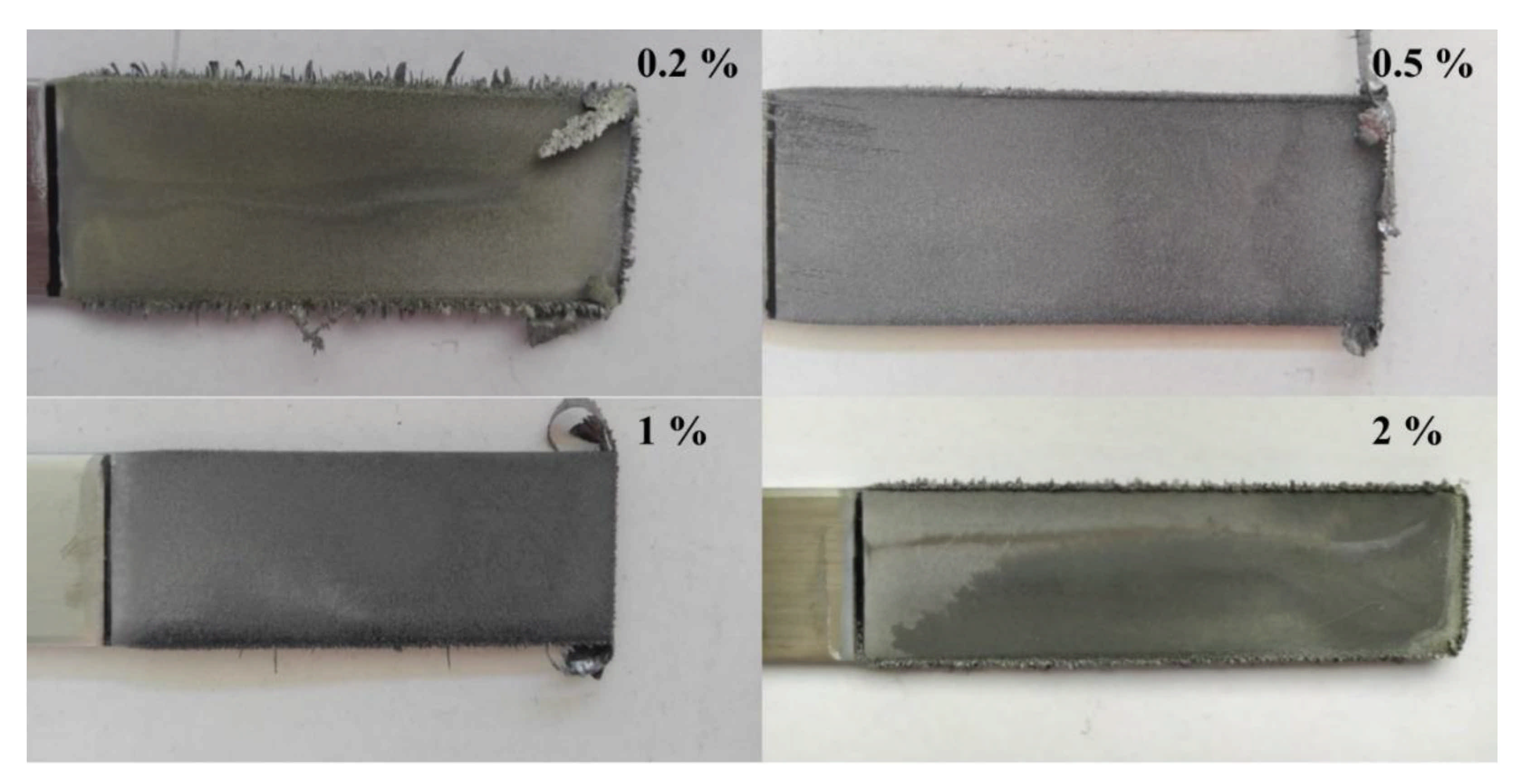
The electrolyte used in the electrochemical deposition of lead was prepared by diluting a 65% TETA solution (p.a.; Across Organics) with demi water to a final 6% (w/w) amine concentration. The obtained solution was saturated with lead sulfate (p.a.; chemPUR), i.e., lead sulfate was added to mixing an amine–water solution in such an amount to achieve the saturation limit. Non-reacted lead salt was separated using vacuum filtration, and the resultant lead concentration within solution was quantitatively analyzed to be 104 g/L. Electrowinning processes were performed in a batch-type reactor of a lead-containing amine electrolyte, magnetically mixed and heated if needed on a hot plate, as it is presented in Figure 1.
Electrochemical processes were carried out using acid-resistant steel electrodes (assembled: 2 anodes and 1 cathode), with a distance between electrodes of 2.5 cm and a surface area of cathode of 28 cm2. Power was supplied by Siglent SPD3303X (Siglent, Helmond, The Netherlands). The improvement of the electrodeposited lead metal quality was achieved by adding inhibitors responsible for limiting dendritic lead formation. Bone glue (G), ethylene glycol (EG), and polyvinylpyrolidone (PVP) were considered as perspective additives. The basic parameters of electrowinning processes were as following: current density, 100–1000 A/m2; deposition current, 0.28–2.8 A; process time, 2 h; temperature, 20–80 °C; electrolyte volume, 400 cm3; electrolyte additives in amount, 50–200 mg/L for G), 0.2–2% (w/w) for EG, and 0.2–5 g/L for PVP. The electrodes were made of 316 L stainless steel.
The produced lead deposits were qualitatively and quantitatively analyzed. At first, the quality was visually examined regarding the presence of cracks, discoloration, compactness, dendrites, and layer smoothness. Photo were recorded using a photo camera (Nokia, Espoo, Finland). Additionally, low-magnification microscopic images were registered using a metalographic optical microscope (Olympus, Tokyo, Japan), Olympus GX71 equipped with Olympus DP70 camera and Stream Motion software Version 1.8. XRD analysis was performed using Rigaku MiniFlex 600 (Rigaku, Tokyo, Japan) with Cu Kα at a wavelength of 1.5406 Å, to evaluate the structure of electrowon metal. Semiquantitative analysis was performed using spectrometer Panalytical Axios Max (Malvern Panalytical, Malvern, UK) to give general data concerning elements present within deposits, while quantitative analysis using the titration method and flame atomic absorption spectroscopy (FAAS) using iCE3300 (Thermo Fischer Scientific, Waltham, MA, USA) to give precise value of elements concentration. A scanning electron microscope (SEM), Zeiss Leo Gemini 1525 equipped with Bruker Quantax XFlash® 6 Bruker Nano SDD microanalyzer (Zeiss, Oberkochen, Germany), was used to show the metallic lead torn from the cathode plate, as well as the elemental composition of the analyzed spot.

3. Results

TETA is a powerful leaching agent that can be used to recover metals from various solid samples. The advantage of TETA is the possibility to recycle a leaching solution, having a close loop and almost effluent-free operation. The mechanism of extraction is not well described; however, it is stated that lead cation is solvated by electron pairs on nitrogen atoms, forming an ionic couple with sulfate ions, as shown in Figure 2.
The lead electrodeposition was examined at current densities in the range of 100–1000 A/m2. Photos with lead deposited at various current densities are presented in a Figure 3.
Typically, at lower current densities, more compact well-adhered deposits were obtained, while an increase in current density led to dendritic metal formation. Dendrites first appeared at the bottom edge of cathode, then covered side edges at higher current densities and finally led to the total exfoliation of the deposited layer within the whole surface. Lead braids were observed for metal deposited at a current density of 400 A/m2 and higher. However, at 400 A/m2, dendrites were observed only in the lower part of electrode with a compact metal layer over the rest of electrode. At 800 A/m2 and 1000 A/m2, the inner part of electrode was covered by a loose lead fragments, which easily detached when moving the electrode, and dense dendrites on the edges. On the contrary, a very low current density, i.e., 100 A/m2, revealed the discoloration of the deposited lead. The calculated current efficiency dropped from 99.98% at 100 A/m2 to 93.74% at 1000 A/m2.
Visually, the best quality of deposited lead was obtained at 200 A/m2. Therefore, this current density was further used to examine effects of temperature. The electrolytes were heated on a hot plate to 40 °C, 60 °C, and 80 °C to evaluate the effects of temperature on lead electrodeposition. Polyamines are viscous liquid, and even in their water solutions, there may be observed local concentration gradients. It was found that starting from room temperature up to 40 °C, lead layers had low amount of dendrites; however, some pale yellow discoloration was still observed (Figure 4).
This can be attributed to the thin surface layer of amine, either co-deposited with lead or stuck to the most outer lead particles layer during drawing electrodes from the electrolyte. It was confirmed by elemental analysis of obtained lead, which revealed a 3% carbon content. At temperature as high as 60 °C, discoloration was significantly reduced that may be attributed to the lower viscosity of the TETA solution and its better dripping from the deposited lead. Additionally, bigger grains and almost no lead dendrites were observed. At the highest examined temperature, metal was deposited less uniformly with significantly coarser grains.
Different types of electrolytic cell additives were examined to inhibit dendritic lead formation and produce more compact deposits. The selected inhibitors were G, EG, and PVP. G was added to the electrolyte in amounts of 50 mg/L, 75 mg/L, 100 mg/L, and 200 mg/L. It was found that a gradual increase in B dose visually improved lead quality, resulting in a uniformly deposited metallic layer without damages and contaminations, easily separated from the steel plate (Figure 5).
The calculated current efficiency at 200 mg/L was as high as 99.2%. Unfortunately, the cathodic deposit (4.29 g) was composed of merely 87.3% Pb as well as 12.6% O, 0.06% Fe, and 0.01% Ni. EG was used in four doses of 0.2%, 0.5%, 1%, and 2% (w/w) (i.e., from 0.8 to 8 mL). Lead deposits with a good quality were produced within the whole examined range of the examined additive; however, some small dendritic lead can be found on the plate edges at 0.2% of EG. The color of deposits and the layer thickness were also satisfactory (Figure 6).
The addition of 2% of EG to the electrolyte allowed electrodepositing 4.38 g of lead on a cathode with a current efficiency of 99.3%. The quantitative analysis of the deposited lead showed 99.9% Pb, 0.09% Fe, and 0.02% Ni. Using EG, it was possible to inhibit both dendrites formation and adhesion of amine on the metal layer.
PVP, the water-soluble polymer used in many technical applications, was added in amounts of 0.2 g/L, 0.5 g/L, 1 g/L, and 5 g/L (Figure 7). At lower polymer concentrations, a multicolor shade was observed, which can be attributed to the insufficient rinsing of deposits. At 1 g/L and 5 g/L, surface layers were compact and unicolor. One important advantage of PVP application was the fact of very easy disassembly of lead deposit from the steel plate. In contrast to EG, there were no significant differences in product quality, depending on the amount of added inhibitor, with very fine crystalline materials. At a PVP concentration of 1 g/L, 4.32 g of cathodic deposits containing 90.7% Pb, 9.25% O, 0.05% Fe, and 0.01% Ni were produced. The current efficiency was 99.90%.
Despite very good-looking lead deposit obtained with PVP, the purity of the metal layer was unsatisfactory. This can be attributed to the high molecular mass of the polymer and its steric interaction with the lead–amine complex, resulting in the co-deposition of PVP.
Further analysis using XRD was used to examine the crystallography of lead deposits. A torn lead layer was cut in a small 1 cm × 1 cm square maintaining possibly a flat surface and investigated by X-rays. The analyzed samples were limited to those obtained at 60 °C with three different inhibitors. Strong signals at 31° (111), 36.4° (200), 52° (220), 62° (311), 65° (222), 85° (331), and 88° (420) were attributed to lead metal. These peaks can be found in all samples. The rest of signals were attributed to various lead oxide structures such as PbO, Pb5(CO3)3O(OH)2 (plumbonacrite) and 3PbO·H2O (hydrated lead oxide). Some low-intensity signals that can be assigned to carbon matters can be also found. The program used to evaluate XRD patterns assigned these organic peaks to the compound of a formula C20H22O8; however, this was simplified in Figure 8 as organic carbon labelled as Corg. These may originate from TETA, as well as inhibitors. The highest relative signal intensity was found for the PVP-modified amine electrolyte, which may arise from the most crystalline lead deposit. Metallic lead was the main phase, present in all materials. Similarly, other lead phases were present in varied quantities of all examined deposits. Therefore, for clarity, peaks identification was presented above the PVP sample, but in fact these concerned all patterns.
Main process parameters, including the current and the voltage of a bath as well as the calculated energy consumption and mass of the obtained lead metal within 2 h of the process, are presented in Table 1.
The low-magnification images of lead deposits obtained using a metallographic microscope showed coarser surfaces for baths with G and EG addition (Figure 9). Metal deposits were in the form of small tiles arranged in a disordered way (400×). This may result from the fast growing of metal grains. A completely different situation can be observed for the PVP-modified bath with a smooth and compact layer, composed of fine crystalline grains (5×) (which were hard to observe at higher magnifications because of excess of reflexes).
In-depth morphology observation was performed using an SEM. SEM images presented in Figure 10 showed that lead deposited from baths with a G addition resulted in an intriguing surface morphology. The deposits were not uniform with a compact inner side of electrode and rugged closer to the edges. This outer area was composed of smaller flake-like growths with additional regular- and rectangular-shape metal particles.
On the contrary, EG produced very uniform and dense lead deposits through the electrode. In spite of densely packed lead crystals, some voids can be noticed, which indicated the random growth of lead deposits. Although visual observation and metallographic microscopic images showed a very smooth surface of lead deposits obtained from the PVP-modified electrolyte bath, SEM images revealed diversified layer thickness and particles with an irregular shape and size. These are mainly responsible for lower lead contents and increased amounts of the electrolyte agglomerated and trapped between metal particles.

4. Conclusions

Aliphatic amines are perspective-leaching agents for various metal-containing feedstocks. The most convenient way to extract metal from amine solutions is simple precipitation. Less popular is an ion exchange method, as there arise a problem of reaction resin with amine. Here, it was proposed to electrodeposit lead metal from a synthetic aqueous solution of TETA containing lead sulfate. These results can be a big advantage in a lot of hydrometallurgical processes. The examination of the temperature and current density showed that the optimum conditions for lead deposition are a temperature of 60 °C and a current density of 200 A/m2. Increases in current density above this value led to detrimental dendritic lead growth, which caused the shortcut of cells. Similarly, decreases in temperature from 60 °C to room temperature caused dendrites formation and the discoloration of lead deposits caused by the higher viscosity of amines at lower temperatures and its sticking to metal surface. The addition of inhibitors, such as G, EG, and PVP, in a specific amount strongly improved the quality of the produced metal. It was suggested that EG produced the highest quality lead deposits with the lowest contamination content.

Author Contributions

Conceptualization, M.C.; methodology, M.C.; formal analysis, W.M. and Ł.H.; investigation, S.O. and P.K.; data curation, M.C. and K.L.-S.; writing—original draft preparation, M.C.; writing—review and editing, M.D. and P.K.; visualization, S.O.; supervision, Ł.H. and K.L.-S. All authors have read and agreed to the published version of the manuscript.

Funding

This work was funded by statutory grant from the ŁUKASIEWICZ—Institute of Non-Ferrous Metals, Gliwice, Poland, entitled “Lead electrowinning from amine-containing leaching solutions”, work code 0332026009.

Institutional Review Board Statement

Not applicable.

Informed Consent Statement

Not applicable.

Data Availability Statement

The data presented in this study are available on request from the corresponding author.

Conflicts of Interest

The authors declare no conflict of interest.

References

  1. Lassina, A.; Piantonea, P.; Burnola, A.; Bodénana, F.; Chateaub, L.; Lerougea, C.; Crouzeta, C.; Guyonneta, D.; Bailly, L. Reactivity of waste generated during lead recycling: An integrated study. J. Hazard. Mater. 2017, 139, 430. [Google Scholar] [CrossRef] [PubMed]
  2. Kim, E.; Horckmans, L.; Spooren, J.; Vrancken, K.C.; Quaghebeur, M.; Broos, K. Selective leaching of Pb, Cu, Ni and Zn from secondary lead smelting residues. Hydrometallurgy 2017, 169, 372. [Google Scholar] [CrossRef]
  3. Aparajith, B.; Mohanty, D.B.; Gupta, M.L. Recovery of enriched lead–silver residue from silver-rich concentrate of hydrometallurgical zinc smelter. Hydrometallurgy 2010, 105, 127. [Google Scholar] [CrossRef]
  4. Raghavan, R.; Mohanan, P.K.; Patnaik, S.C. Innovative processing technique to produce zinc concentrate from zinc leach residue with simultaneous recovery of lead and silver. Hydrometallurgy 1998, 48, 225. [Google Scholar] [CrossRef]
  5. Frıas, C.; Dıaz, G.; Ocana, N.; Lozano, J.I. Silver, gold and lead recovery from bioleaching residues using the PLINT process. Miner. Eng. 2002, 15, 877. [Google Scholar] [CrossRef]
  6. Şahin, M.; Erdem, M. Cleaning of high lead-bearing zinc leaching residue by recovery of lead with alkaline leaching. Hydrometallurgy 2015, 153, 170. [Google Scholar] [CrossRef]
  7. Ye, M.; Li, G.; Yan, P.; Zheng, L.; Sun, S.; Huang, S.; Li, H.; Chen, Y.; Yang, L.; Huang, J. Production of lead concentrate from bioleached residue tailings by brine leaching followed by sulfide precipitation. Sep. Purif. Technol. 2017, 183, 366. [Google Scholar] [CrossRef]
  8. Xing, P.; Wang, C.; Wang, L.; Ma, B.; Chen, Y. Hydrometallurgical recovery of lead from spent lead-acid battery paste via leaching and electrowinning in chloride solution. Hydrometallurgy 2019, 189, 105134. [Google Scholar] [CrossRef]
  9. Chen, C.-S.; Shih, Y.-J.; Huang, Y.-H. Recovery of lead from smelting fly ash of waste lead-acid battery by leaching and electrowinning. Waste Manag. 2016, 52, 212–220. [Google Scholar] [CrossRef]
  10. Tang, L.; Tang, C.B.; Xiao, J.; Zeng, P.; Tang, M.; Wang, Z.; Zhang, Z. A cleaner process for lead recovery from lead-containing hazardous solid waste and zinc leaching residue via reducing-matting smelting. J. Clean. Prod. 2019, 241, 118328. [Google Scholar] [CrossRef]
  11. Chmielarz, A.; Szołomicki, Z.; Mrozowski, J.; Prajsnar, R.; Wolarek, J.; Skawiński, L.; Celarek, A.; Hanzel, M. Piloting amine battery paste desulphurisation process. In Proceedings of the Pb Zn 2010 Symposium, Vancouver, BC, Canada, 3–6 October 2010; p. 747. [Google Scholar]
  12. Yanakieva, V.P.; Haralampiev, G.A.; Lyakov, N.K. Desulphurization of the damped lead battery paste with potassium carbonate. J. Power Sources 2000, 85, 178–180. [Google Scholar] [CrossRef]
  13. Lyakov, N.K.; Atanasova, D.A.; Vassilev, V.S.; Haralampiev, G.A. Desulphurization of damped battery paste by sodium carbonate and sodium hydroxide. J. Power Sources 2007, 171, 960–965. [Google Scholar] [CrossRef]
  14. Zhang, J.; Yi, L.; Yang, L.; Huang, Y.; Zhou, W.; Bian, W. A new pre-desulphurization process of damped lead battery paste with sodium carbonate based on a “surface update”concept. Hydrometallurgy 2016, 160, 123–128. [Google Scholar] [CrossRef]
  15. Volpe, M.; Oliveri, D.; Ferrara, G.; Salvaggio, M.; Piazza, S.; Italiano, S.; Sunseri, C. Metallic lead recovery from lead-acid battery paste by urea acetate dissolution and cementation on iron. Hydrometallurgy 2009, 96, 123–131. [Google Scholar] [CrossRef]
  16. Kumar, R.V.; Petrova Kotzeva, V.; Sonmez, S. Lead Recycling. US8323376B2, 4 December 2012. Available online: https://patents.google.com/patent/US8323376B2/en (accessed on 23 August 2021).
  17. Pan, J.; Zhang, C.; Sun, Y.; Wang, Z.; Yang, Y. A new process of lead recovery from waste lead-acid batteries by electrolysis of alkaline lead oxide solution. Electrochem. Commun. 2012, 19, 70–72. [Google Scholar] [CrossRef]
  18. Ye, L.; Duan, L.; Liu, W.; Hu, Y.; Ouyang, Z.; Yang, S.; Xia, Z. Facile method for preparing a nano lead powder by vacuum decomposition from spent lead-acid battery paste: Leaching and desulfuration in tartaric acid and sodium tartrate mixed lixivium. Hydrometallurgy 2020, 197, 105450. [Google Scholar] [CrossRef]
  19. Zhang, Y.; Qu, R.; Sun, C.; Chen, H.; Wang, C.; Ji, C.; Yin, P.; Sun, Y.; Zhang, H.; Niu, Y. Comparison of synthesis of chelating resin silica-gel-supported diethylenetriamine and its removal properties for transition metal ions. J. Hazard. Mater. 2009, 163, 127–135. [Google Scholar] [CrossRef] [PubMed]
  20. Huang, Z.; Jiang, L.; Wu, P.; Dang, Z.; Zhu, N.; Liu, Z.; Luo, H. Leaching characteristics of heavy metals in tailings and their simultaneous immobilization with triethylenetetramine functioned montmorillonite (TETA-Mt) against simulated acid rain. Environ. Pollut. 2020, 266, 115236. [Google Scholar] [CrossRef]
  21. Gélinas, S.; Finch, J.A.; Rao, S.R. Electrowinning of Nickel and Copper from Ethylenediamine Complexes. Can. Q. 2002, 41, 319–325. [Google Scholar] [CrossRef]
  22. Rodriguez Rodriguez, N.; Onghena, B.; Binnemans, K. Recovery of Lead and Silver from Zinc Leaching Residue Using Methanesulfonic Acid. ACS Chem. Eng. 2019, 7, 19807–19815. [Google Scholar] [CrossRef] [Green Version]
  23. Szolomicki, Z.; Chmielarz, A.; Smieszek, Z.; Myczkowski, Z.; Mrozowski, J.; Wasilewski, W.; Gotfryd, L.; Prajsnar, R.; Buzek, L.; Raszka, U.; et al. Method for Desulphurization of Battery Paste. EP2333895A1, 13 June 2012. Available online: https://patents.google.com/patent/EP2333895A1/en?oq=EP2333895A1%2c+2009 (accessed on 23 August 2021).
  24. Jordan, M. Electrodeposition of lead and lead alloys. In Modern Electroplating, 5th ed.; Schlesinger, M., Paunovic, M., Eds.; Wiley: Pennington, NJ, USA, 2010; pp. 249–263. [Google Scholar]
  25. Exposito, E.; Gonzalez-Garcıa, J.; Bonete, P.; Montiel, V.; Aldaz, A. Lead electrowinning in a fluoborate medium. Use of hydrogen diffusion anodes. J. Power Sources 2000, 87, 137–143. [Google Scholar] [CrossRef]
Figure 1. Schematic presentation of the electrowinning bath.
Metals 11 01330 g001
Figure 2. Solvation of lead sulfate molecule by triethylenetetramine.
Metals 11 01330 g002
Figure 3. Photos of lead electrodeposited from the triethylenetetramine solution at different current densities.
Metals 11 01330 g003
Figure 4. Photos of lead electrodeposited from triethylenetetramine solution at different temperatures.
Metals 11 01330 g004
Figure 5. Photos of electrodeposited lead at different concentrations of bone glue as an inhibitor.
Metals 11 01330 g005
Figure 6. Photos of the electrodeposited lead at different concentrations of ethylene glycol as an inhibitor.
Metals 11 01330 g006
Figure 7. Photos of electrowon lead at different polyvinylpyrolidone (PVP) concentrations.
Metals 11 01330 g007
Figure 8. XRD patterns of lead deposits obtained using different inhibitors.
Metals 11 01330 g008
Figure 9. Metallographic microscopic images of lead electrodeposited at 60 °C using different inhibitors.
Metals 11 01330 g009
Figure 10. SEM images of lead deposits produced using different inhibitors.
Metals 11 01330 g010
Table 1. Main process parameters calculated for different baths.
HeadingsCurrent Density (A/m2)Current
(A)
Voltage
(V)
Cathodic Current Efficiency (%)Energy
Consumption (kWh/t Pb)
Mass of Cathodic Deposit (g)
G2000.562.0299.205274.29
EG2000.561.8999.275174.38
PVP2000.561.9299.904984.32
Publisher’s Note: MDPI stays neutral with regard to jurisdictional claims in published maps and institutional affiliations.

