
Deposition of Nickel-Based Superalloy Claddings on Low Alloy Structural Steel by Direct Laser Deposition

 ,
,  , ,
, , 

Abstract
:1. Introduction
2. Materials and Methods
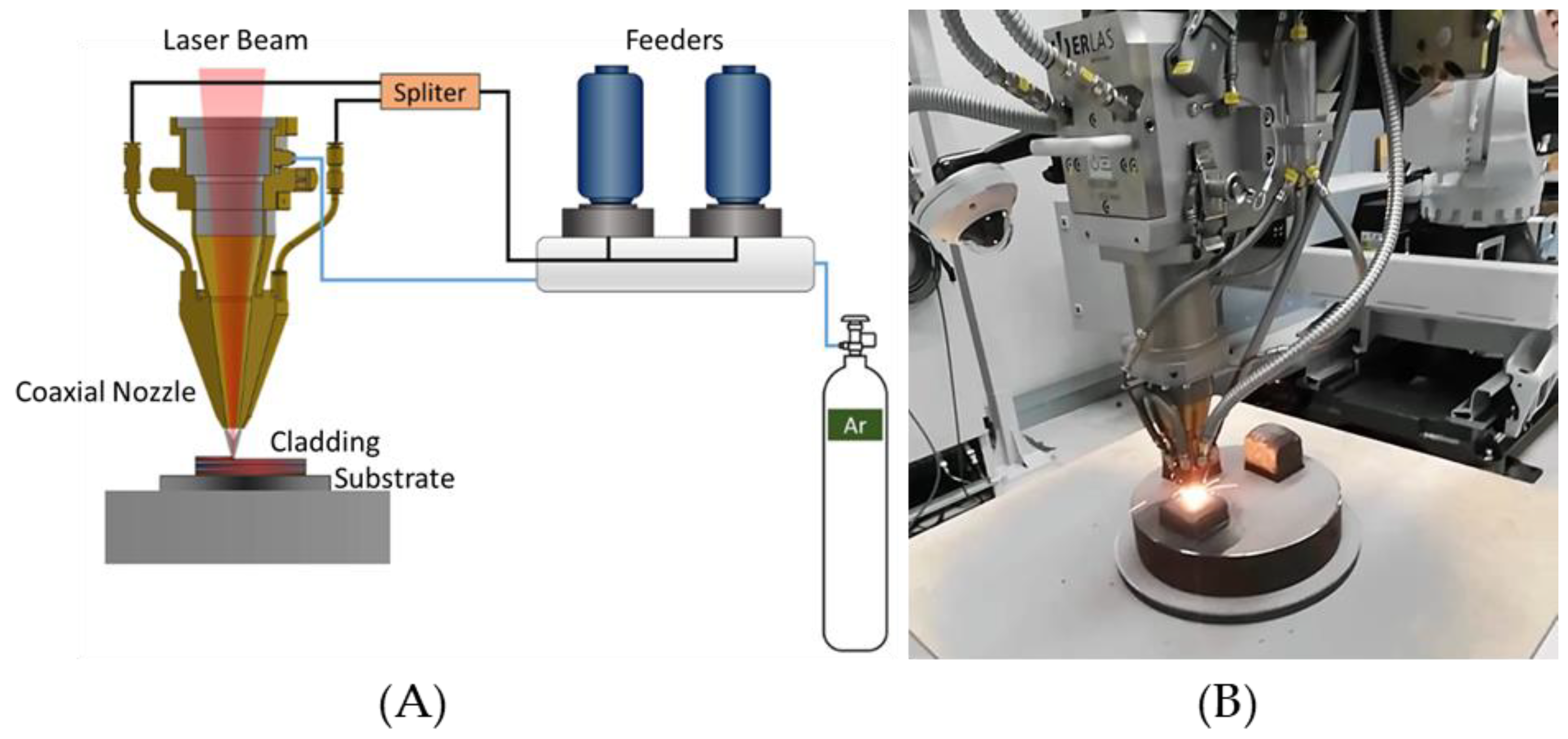
2.1. DLD System Setup
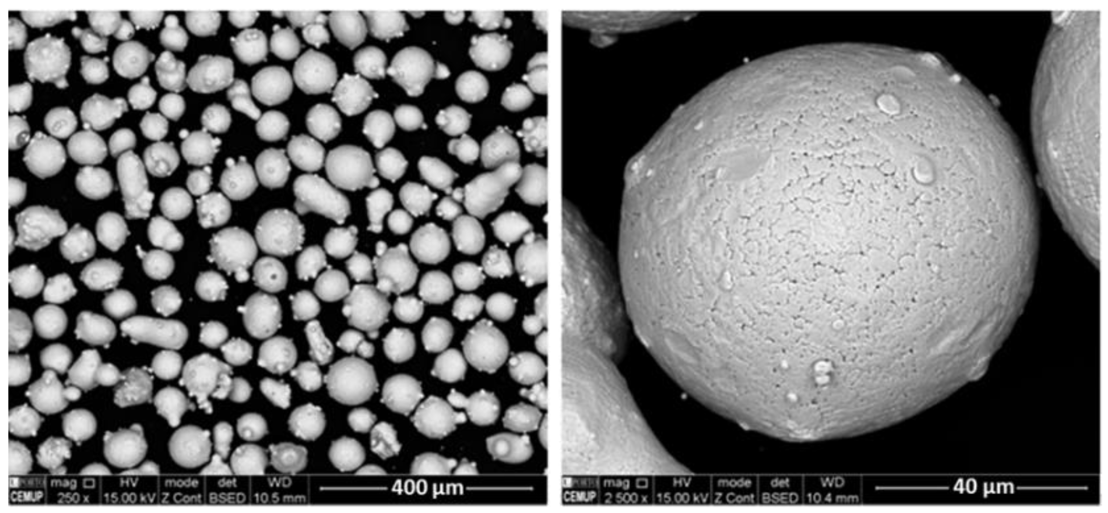
2.2. Feedstock Powder and Substrate
2.3. Process Parameters
2.4. Mechanical and Microstructural Characterisation
3. Results and Discussion
3.1. Processing Effects
3.2. Microstructures and Mechanical Characterisation of the DLD Samples
3.3. Microhardness Measurements
4. Conclusions
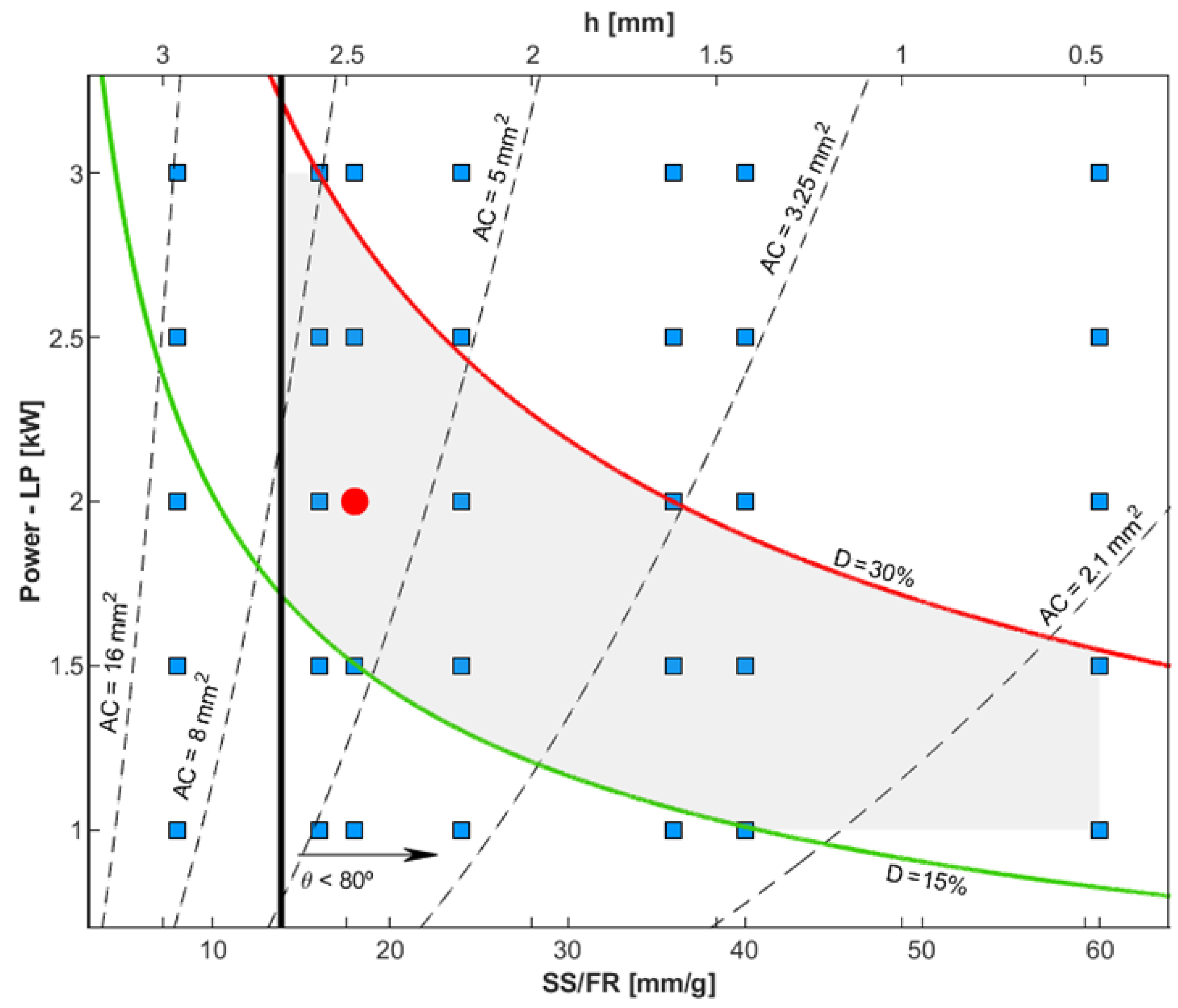
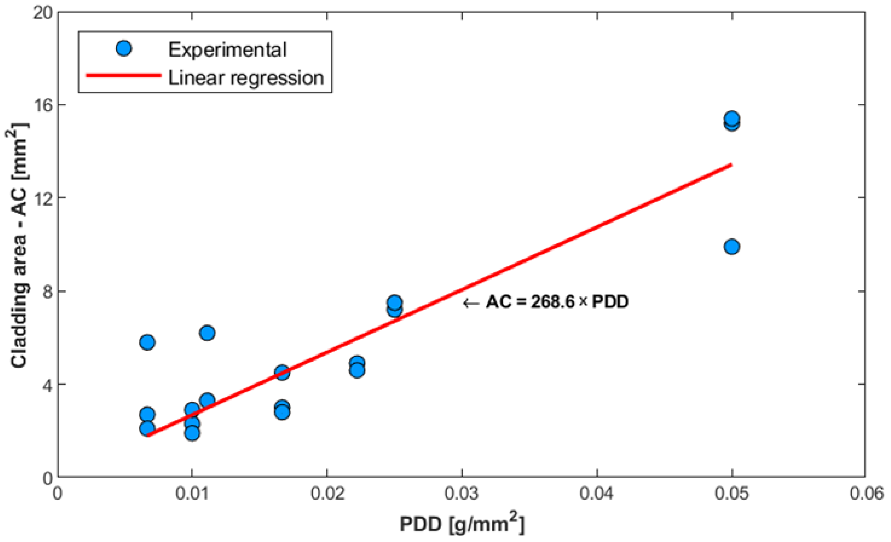
- A DLD process window map considering processing variables shows that several combinations can be used. However, the cladding produced with 2 kW of laser power, a scanning speed of 6 mm/s, and a 20 g/min feed rate presented adequate dilution and wettability.
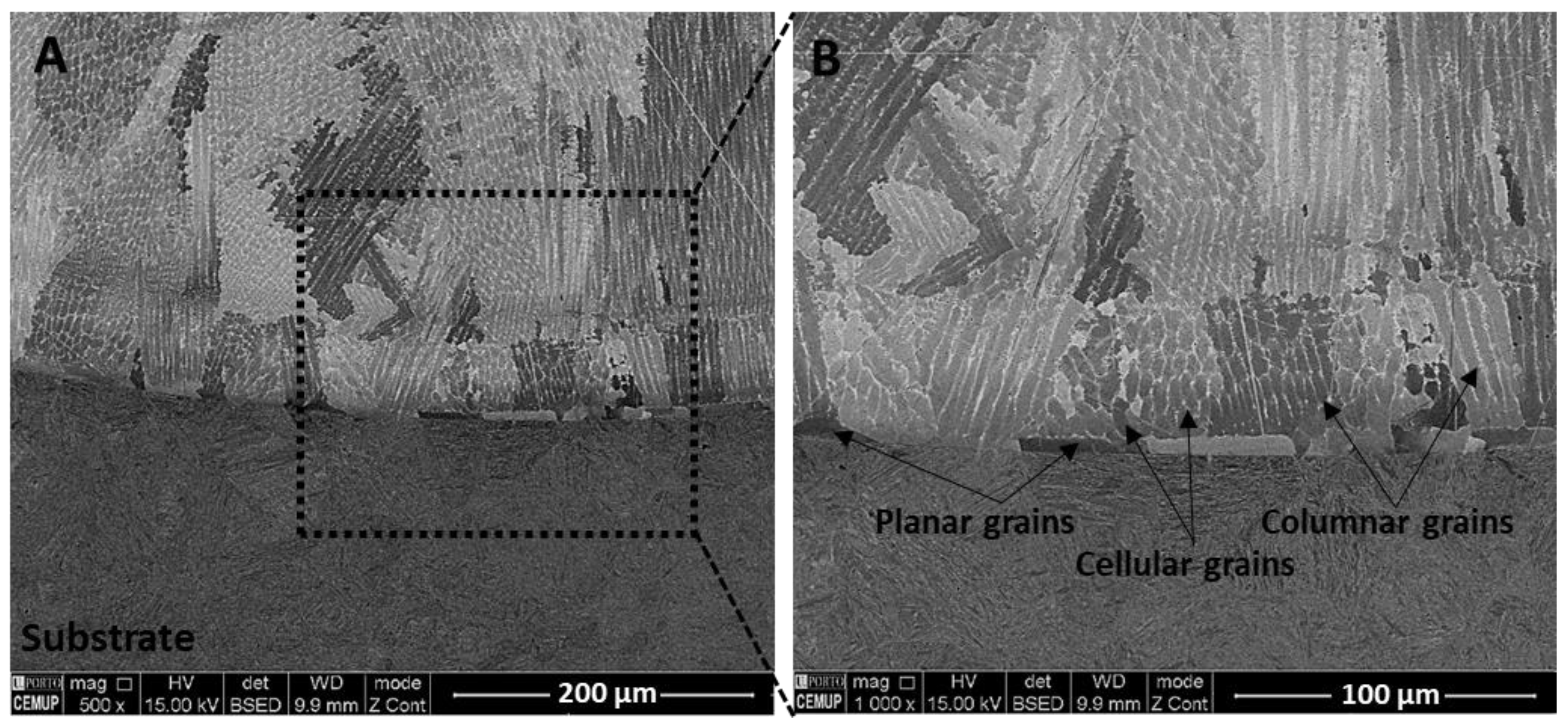
- The deposited layers were produced without significant structural defects such as cracks, pores, or other types of discontinuities.
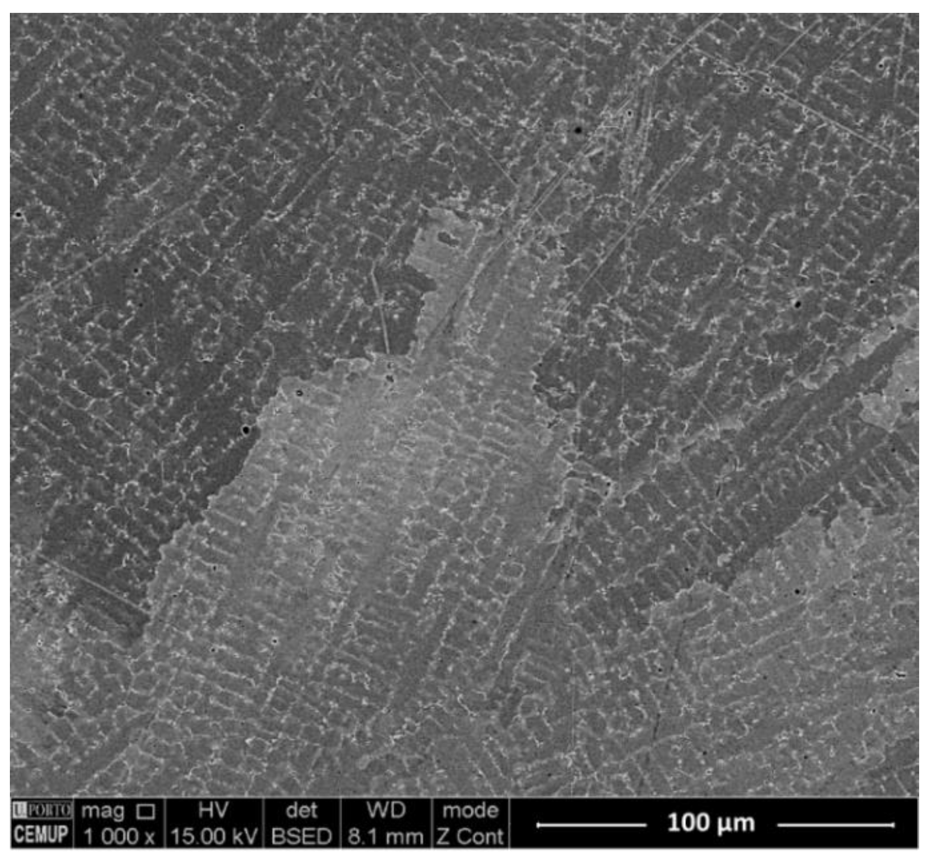
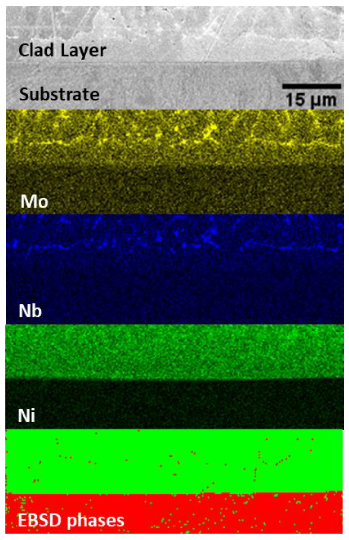
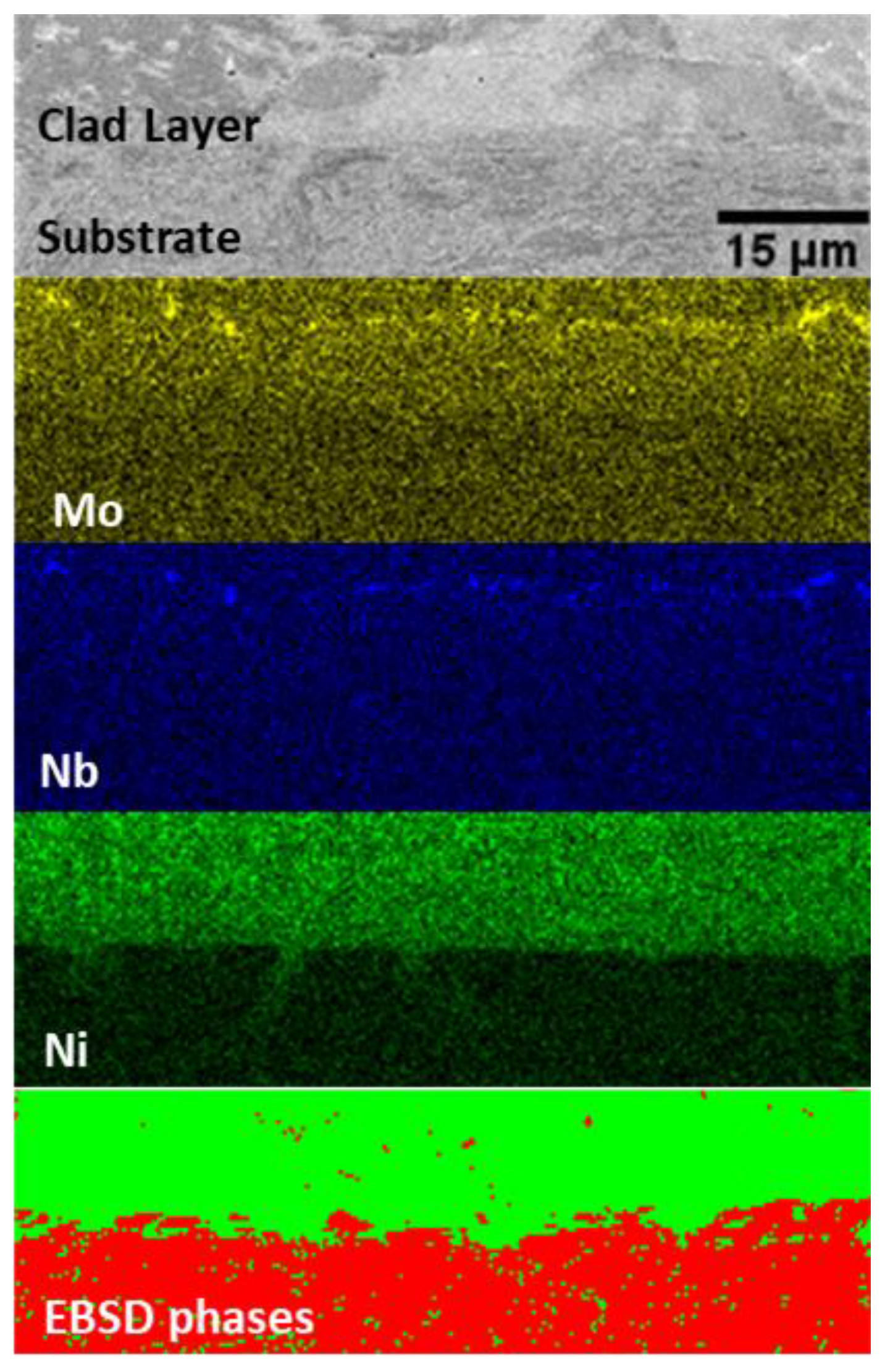
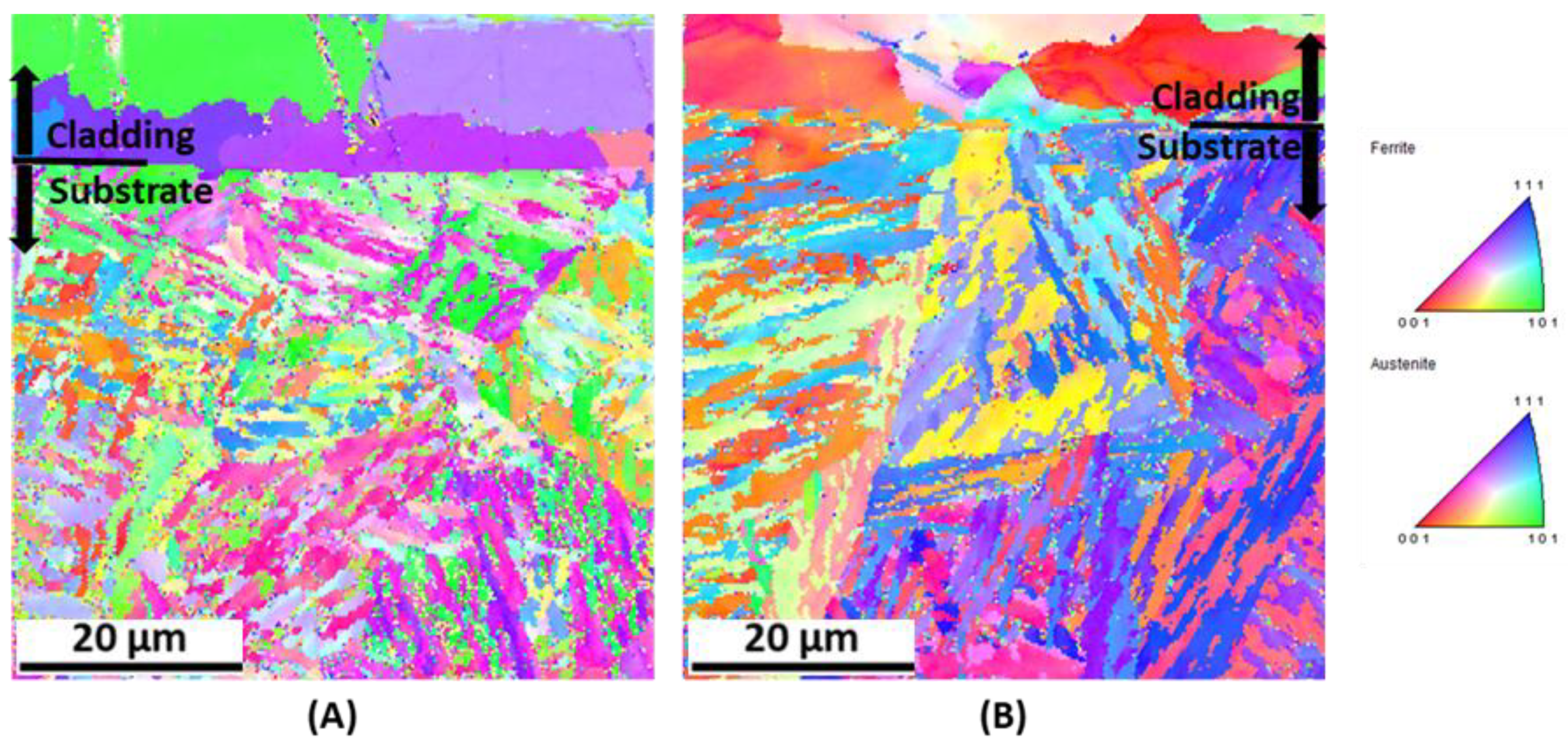
- Substrate preheating to 300 °C influences the microstructure of the cladding/substrate interface, reducing the formation of the deleterious Laves phase.
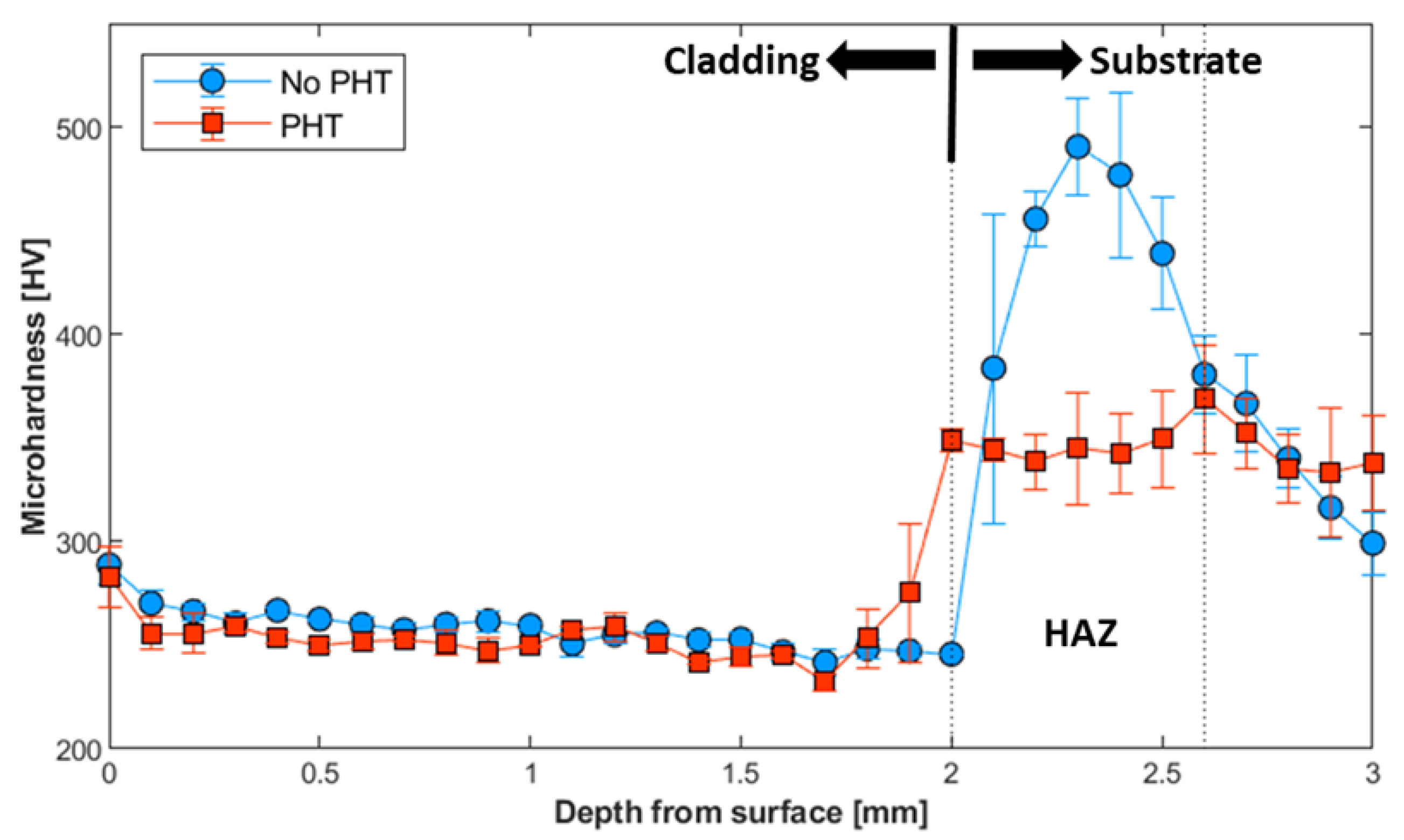
- PHT also alters the hardness profile, mainly in the heat-affected zone, due to modification of the martensite microstructure and increased residual austenite.
Author Contributions
Funding
Institutional Review Board Statement
Informed Consent Statement
Data Availability Statement
Acknowledgments
Conflicts of Interest
References
- Bian, L.; Shamsaei, N.; Usher, J.M. Laser-Based Additive Manufacturing of Metal Parts, 1st ed.; CRC Press: Boca Raton, FL, USA, 2018. [Google Scholar]
- Ur Rahman, N.; Matthews, D.T.; de Rooji, M.; Khorasani, A.M.; Gibson, I.; Cordova, L.; Römer, G. An Overview: Laser-Based Additive Manufacturing for High Temperature Tribology. Front. Mech. Eng. 2019, 5, 1–15. [Google Scholar] [CrossRef]
- Thompson, S.M.; Bian, L.; Shamsaei, N.; Yadollahi, A. An overview of Direct Laser Deposition for additive manufacturing; Part I: Transport phenomena, modeling and diagnostics. Addit. Manuf. 2015, 8, 36–62. [Google Scholar] [CrossRef]
- Song, L.; Bagavath-Singh, V.; Dutta, B.; Mazumder, J. Control of melt pool temperature and deposition height during direct metal deposition process. Int. J. Adv. Manuf. Technol. 2012, 58, 247–256. [Google Scholar] [CrossRef]
- Petrat, T.; Graf, B.; Gumenyuk, A.; Rethmeier, M. Laser metal deposition as repair technology for a gas turbine burner made of inconel 718. Phys. Procedia 2016, 83, 761–768. [Google Scholar] [CrossRef]
- Alimardani, M.; Fallah, V.; Khajepour, A.; Toyserkani, E. The effect of localised dynamic surface preheating in laser cladding of Stellite 1. Surf. Coatings Technol. 2010, 204, 3911–3919. [Google Scholar] [CrossRef]
- Leunda, J.; García Navas, V.; Soriano, C.; Sanz, C. Effect of laser tempering of high alloy powder metallurgical tool steels after laser cladding. Surf. Coatings Technol. 2014, 259, 570–576. [Google Scholar] [CrossRef]
- Dass, A.; Moridi, A. State of the art in directed energy deposition: From additive manufacturing to materials design. Coatings 2019, 9, 418. [Google Scholar] [CrossRef] [Green Version]
- Lahrour, Y.; Brissaud, D. A Technical Assessment of Product/Component Re-manufacturability for Additive Remanufacturing. Procedia CIRP 2018, 69, 142–147. [Google Scholar] [CrossRef]
- Kush, M. Advanced Manufacturing Technologies Modern Machining Advanced Joining Sustainable Manufacturing; Springer International Publishing: New York, NY, USA, 2018; p. 294. [Google Scholar] [CrossRef] [Green Version]
- Pinkerton, A.J.; Wang, W.; Li, L. Component repair using laser direct metal deposition. Proc. Inst. Mech. Eng. B J. Eng. Manuf. 2008, 222, 827–836. [Google Scholar] [CrossRef]
- Vilar, R.; Almeida, A. Repair and manufacturing of single crystal Ni-based superalloys components by laser powder deposition—A review. J. Laser Appl. 2015, 27, S17004. [Google Scholar] [CrossRef]
- Abioye, T.E.; McCartney, D.G.; Clare, A.T. Laser cladding of Inconel 625 wire for corrosion protection. J. Mater. Process. Technol. 2015, 217, 232–240. [Google Scholar] [CrossRef] [Green Version]
- Marchese, G.; Colera, X.G.; Calignano, F.; Lorusso, M.; Biamino, S.; Minetola, P.; Manfredi, D. Characterization and Comparison of Inconel 625 Processed by Selective Laser Melting and Laser Metal Deposition. Adv. Eng. Mater. 2017, 19, 1–9. [Google Scholar] [CrossRef]
- Gonzalez, J.A.; Mireles, J.; Stafford, S.W.; Perez, M.A.; Terrazas, C.A.; Wicker, R.B. Characterization of Inconel 625 fabricated using powder-bed-based additive manufacturing technologies. J. Mater. Process. Technol. 2019, 264, 200–210. [Google Scholar] [CrossRef]
- Long, Y.T.; Nie, P.L.; Li, Z.G.; Huang, J.; Li, X.; Xu, X.M. Segregation of niobium in laser cladding Inconel 718 superalloy. Trans. Nonferrous Met. Soc. China 2016, 26, 431–436. [Google Scholar] [CrossRef]
- Xiao, H.; Li, S.; Han, X.; Mazumder, J.; Song, L. Laves phase control of Inconel 718 alloy using quasi-continuous-wave laser additive manufacturing. Mater. Des. 2017, 122, 330–339. [Google Scholar] [CrossRef]
- Singh, G.; Vasudev, H.; Bansal, A.; Vardhan, S.; Sharma, S. Microwave cladding of Inconel-625 on mild steel substrate for corrosion protection. Mater. Res. Express 2020, 7. [Google Scholar] [CrossRef]
- Feng, K.; Feng, K.; Chena, Y.; Denga, P.; Li, Y.; Zhao, H.; Lu, F.; Li, R.; Jian, H.; Li, Z. Improved high-temperature hardness and wear resistance of Inconel 625 coatings fabricated by laser cladding. J. Mater. Process. Technol. 2017, 243, 82–91. [Google Scholar] [CrossRef]
- Farahmand, P.; Kovacevic, R. Laser cladding assisted with an induction heater (LCAIH) of Ni-60%WC coating. J. Mater. Process. Technol. 2015, 222, 244–258. [Google Scholar] [CrossRef]
- Wang, Z.; Zhao, J.; Zhao, Y.; Zhang, H.; Shi, F. Microstructure and microhardness of laser metal deposition shaping K465/stellite-6 laminated material. Metals 2017, 7, 512. [Google Scholar] [CrossRef] [Green Version]
- Bennett, J.; Dudas, R.; Cao, J.; Ehmann, K.; Hyatt, G. Control of Heating and Cooling for Direct Laser Deposition Repair of Cast Iron Components. In Proceedings of the International Symposium on Flexible Automation, ISFA 2016, Cleveland, OH, USA, 1–3 August 2016. [Google Scholar]
- The Laser Repair Process of High-Speed Gear Transmission Body with Better Wear Resistance and Higher Hardness. Patent CN106222651A, 14 December 2016.
- Sadhu, A.; Choudhary, A.; Sarkar, S.; Nair, A.M.; Nayak, P.; Pawar, S.D.; Muvvala, G.; Pal, S.K.; Nath, A.K. A study on the influence of substrate preheating on mitigation of cracks in direct metal laser deposition of NiCrSiBC-60%WC ceramic coating on Inconel 718. Surf. Coatings Technol. 2020, 389, 125646. [Google Scholar] [CrossRef]
- Shim, D.S.; Baek, D.S.; Lee, S.B.; Yu, J.H.; Choi, Y.S.; Park, S.H. Influence of heat treatment on wear behavior and impact toughness of AISI M4 coated by laser melting deposition. Surf. Coatings Technol. 2017, 328, 219–230. [Google Scholar] [CrossRef]
- He, W.; Shi, W.; Li, J.; Xie, H. In-situ monitoring and deformation characterisation by optical techniques; part I: Laser-aided direct metal deposition for additive manufacturing. Opt. Lasers Eng. 2019, 122, 74–88. [Google Scholar] [CrossRef]
- Sun, C.; Fu, P.X.; Liu, H.W.; Liu, H.H.; Du, N.Y. Effect of tempering temperature on the low temperature impact toughness of 42CrMo4-V steel. Metals 2018, 8, 232. [Google Scholar] [CrossRef] [Green Version]
- Steels and Nickel Alloys for Fasteners with Specified Elevated and/or Low Temperature; BSIStandard: London, UK, 2013; ISBN 978 0 580 76784 5.
- Engler, O.; Randle, V. Introduction to texture analysis: Macrotexture, Microtexture and Orientation Mapping, 2rd ed.; CRC Press: Boca Raton, FL, USA, 2010. [Google Scholar]
- Abioye, T.E.; Folkes, J.; Clare, A.T. A parametric study of Inconel 625 wire laser deposition. J. Mater. Process. Technol. 2013, 213, 2145–2151. [Google Scholar] [CrossRef] [Green Version]
- Toyserkani, E.; Khajepour, A.; Corbin, S. Laser Cladding, 1st ed.; CRC Press: Boca Raton, FL, USA, 2004. [Google Scholar]
- Li, C.; Guo, Y.B.; Zhao, J.B. Interfacial phenomena and characteristics between the deposited material and substrate in selective laser melting Inconel 625. J. Mater. Process. Technol. 2017, 243, 269–281. [Google Scholar] [CrossRef]
- Ferreira, A.A.; Darabi, R.; Sousa, J.P.; Cruz, J.M.; Reis, A.R.; Vieira, M.F. Optimization of direct laser deposition of a martensitic steel powder (Metco 42c) on 42CrMo4 steel. Metals 2021, 11, 672. [Google Scholar] [CrossRef]
- Emamian, A.; Corbin, S.F.; Khajepour, A. In-Situ Deposition of Metal Matrix Composite in Fe-Ti-C System Using Laser Cladding Process. Met. Ceram. Polym. Compos. Var. Uses 2011. [Google Scholar] [CrossRef] [Green Version]
- Farshidianfar, M.H.; Khajepour, A.; Gerlich, A.P. Effect of real-time cooling rate on microstructure in Laser Additive Manufacturing. J. Mater. Process. Technol. 2016, 231, 468–478. [Google Scholar] [CrossRef]
- Emamian, A.; Corbin, S.F.; Khajepour, A. Effect of laser cladding process parameters on clad quality and in-situ formed microstructure of Fe-TiC composite coatings. Surf. Coatings Technol. 2010, 205, 2007–2015. [Google Scholar] [CrossRef]
- Ocelík, V.; de Oliveira, U.; de Boer, M.; de Hosson, J.T.M. Thick Co-based coating on cast iron by side laser cladding: Analysis of processing conditions and coating properties. Surf. Coatings Technol. 2007, 201, 5875–5883. [Google Scholar] [CrossRef] [Green Version]
- de Oliveira, U.; Ocelík, V.; De Hosson, J.T.M. Analysis of coaxial laser cladding processing conditions. Surf. Coatings Technol. 2005, 197, 127–136. [Google Scholar] [CrossRef]
- Liu, J.; Li, J.; Cheng, X.; Wang, H. Effect of dilution and macrosegregation on corrosion resistance of laser clad AerMet100 steel coating on 300M steel substrate. Surf. Coatings Technol. 2017, 325, 352–359. [Google Scholar] [CrossRef]
- Le, T.N.; Lo, Y.L. Effects of sulfur concentration and Marangoni convection on melt-pool formation in transition mode of selective laser melting process. Mater. Des. 2019, 179, 107866. [Google Scholar] [CrossRef]
- Marya, M.; Singh, V.; Hascoet, J.-Y.; Marya, S. Metallurgical Investigation of the Direct Energy Deposition Surface Repair of Ferrous Alloys. J. Mater. Eng. Perform. 2018, 27, 813–824. [Google Scholar] [CrossRef]
- Ocelík, V.; Hemmati, I.; De Hosson, J.T.M. The influence of processing speed on the properties of laser surface deposits. Surf. Contact Mech. Incl. Tribol. XII 2015, 1, 93–103. [Google Scholar] [CrossRef] [Green Version]
- Hemmati, I.; Ocelík, V.; De Hosson, J.T.M. Microstructural characterisation of AISI 431 martensitic stainless steel laser-deposited coatings. J. Mater. Sci. 2011, 46, 3405–3414. [Google Scholar] [CrossRef] [Green Version]
- Dinda, G.P.; Dasgupta, A.K.; Mazumder, J. Laser aided direct metal deposition of Inconel 625 superalloy: Microstructural evolution and thermal stability. Mater. Sci. Eng. A 2009, 509, 98–104. [Google Scholar] [CrossRef]
- Naghiyan Fesharaki, M.; Shoja-Razavi, R.; Mansouri, H.A.; Jamali, H. Microstructure investigation of Inconel 625 coating obtained by laser cladding and TIG cladding methods. Surf. Coatings Technol. 2018, 353, 25–31. [Google Scholar] [CrossRef]
- Xiao, H.; Li, S.M.; Xiao, W.J.; Li, Y.Q.; Cha, L.M.; Mazumder, J.; Song, L.J. Effects of laser modes on Nb segregation and Laves phase formation during laser additive manufacturing of nickel-based superalloy. Mater. Lett. 2017, 188, 260–262. [Google Scholar] [CrossRef]
- Knorovsky, G.A.; Cieslak, M.J.; Headley, T.J. Inconel 718 A Solidification Diagram. Metall. Transactions A 1989, 20, 2149–2158. [Google Scholar] [CrossRef]
- Wang, L.; Dong, J.; Tian, Y.; Zhang, L. Microsegregation and Rayleigh number variation during the solidification of superalloy Inconel 718. Mineral. Metall. Mater. 2008, 15, 594–599. [Google Scholar] [CrossRef]
- Dupont, J.N. Solidification of an Alloy 625 Weld Overlay. Metall. Mater. Trans. A 1996, 27, 3612–3620. [Google Scholar] [CrossRef]
- Cieslak, M.J.; Headley, T.J.; Kollie, T.; Romig, A.D. A Melting and Solidification Study of Alloy 625. Met. Mater. Trans. A 1988, 19, 2319–2331. [Google Scholar] [CrossRef]
- Nie, P.; Ojo, O.A.; Li, Z. Numerical modeling of microstructure evolution during laser additive manufacturing of a nickel-based superalloy. Acta Mater. 2014, 77, 85–95. [Google Scholar] [CrossRef]
- Xie, H.; Yang, K.; Li, F.; Sun, C.; Yu, Z. Investigation on the Laves phase formation during laser cladding of IN718 alloy by CA-FE. J. Manuf. Process. 2020, 52, 132–144. [Google Scholar] [CrossRef]
- Chen, Y.; Guo, Y.; Xu, M.; Ma, C.; Zhang, Q.; Wang, L.; Yao, J.; Li, Z. Study on the element segregation and Laves phase formation in the laser metal deposited IN718 superalloy by flat top laser and gaussian distribution laser. Mater. Sci. Eng. A 2019, 754, 339–347. [Google Scholar] [CrossRef]
- Porter, D.A.; Easterling, K.E.; Sherif, M.Y. Phase Transformations in Metals and Alloys, 3rd ed.; CRC Press: Boca Raton, FL, USA, 2009. [Google Scholar]


| Material | Ni | Cr | Mo | Nb | Si | Mn | C | Fe |
|---|---|---|---|---|---|---|---|---|
| M625 | 60.8 | 21.3 | 9.2 | 4.6 | - | - | - | 4.1 |
| 42CrMo4 | - | 1.1 | 0.2 | - | 0.3 | 0.7 | 0.4 | 97.3 |
| Process Parameters | Values |
|---|---|
| Laser power (LP) | 1.0, 1.5, 2.0, 2.5, and 3.0 kW |
| Scanning speed (SS) | 2.0, 4.0, 6.0, and 10.0 mm/s |
| Feed rate (FR) | 10, 15, and 20 g/min |
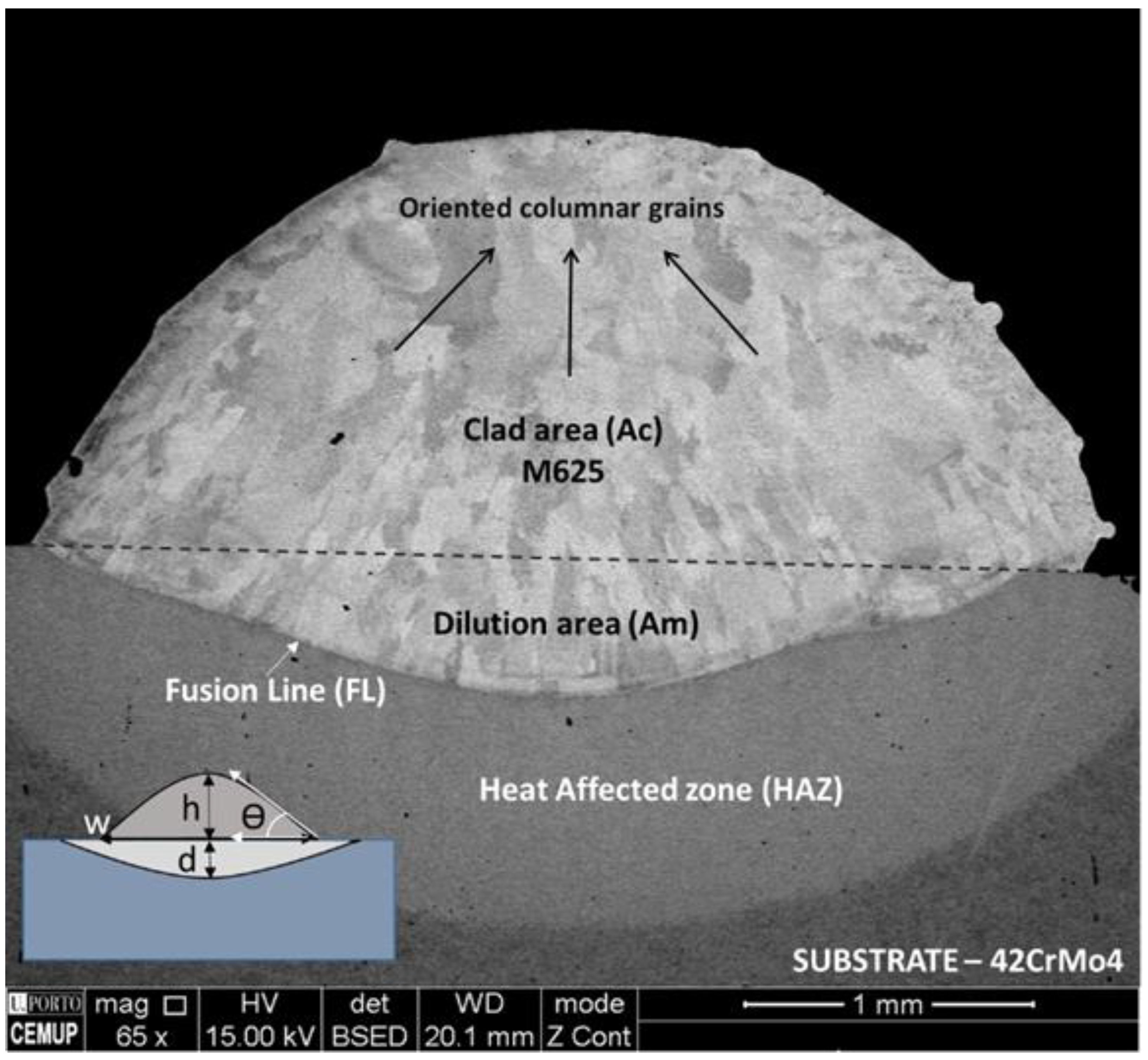
| Sample | Cladding Dimensional Analysis | ||||||
|---|---|---|---|---|---|---|---|
| W (mm) | H (mm) | D (mm) | θ (°) | AC (mm2) | AM (mm2) | D (%) | |
| I1_2_15 | 2.79 | 3.07 | 0.25 | 121 | 9.9 | 0.3 | 2.6 |
| I1_6_15 | 3.07 | 1.22 | 0.06 | 64 | 3.0 | 0.0 | 1.3 |
| I1.5_10_10 | 3.09 | 0.71 | 0.43 | 47 | 5.8 | 2.1 | 26.5 |
| I1.5_10_15 | 3.11 | 1.03 | 0.23 | 64 | 2.3 | 0.2 | 7.3 |
| I2_2_15 | 3.62 | 3.66 | 1.28 | 107 | 15.2 | 3.0 | 16.6 |
| I2_4_15 | 3.50 | 2.47 | 1.12 | 88 | 7.2 | 2.4 | 25.0 |
| I2_6_10 | 3.38 | 1.39 | 1.16 | 53 | 3.3 | 2.3 | 40.6 |
| I2_6_15 | 3.61 | 1.47 | 0.51 | 65 | 4.5 | 1.3 | 22.0 |
| I2_6_20 | 3.63 | 1.71 | 0.56 | 74 | 4.9 | 1.2 | 19.5 |
| I2_10_10 | 3.20 | 1.20 | 0.72 | 58 | 2.7 | 1.1 | 29.1 |
| I2_10_15 | 3.36 | 0.81 | 0.88 | 40 | 1.9 | 1.5 | 45.1 |
| I2.5_10_10 | 3.33 | 0.86 | 1.04 | 49 | 2.1 | 2.3 | 52.1 |
| I2.5_10_15 | 3.36 | 1.23 | 1.00 | 51 | 2.9 | 1.9 | 39.8 |
| I3_2_15 | 5.05 | 3.40 | 2.06 | 99 | 15.4 | 6.6 | 29.9 |
| I3_4_15 | 4.64 | 2.06 | 0.89 | 70 | 7.5 | 2.5 | 25.3 |
| I3_6_10 | 3.89 | 1.85 | 1.08 | 74 | 6.2 | 2.8 | 30.8 |
| I3_6_15 | 4.71 | 0.78 | 0.68 | 37 | 2.8 | 2.6 | 48.0 |
| I3_6_20 | 3.94 | 1.55 | 1.34 | 69 | 4.6 | 3.3 | 41.6 |
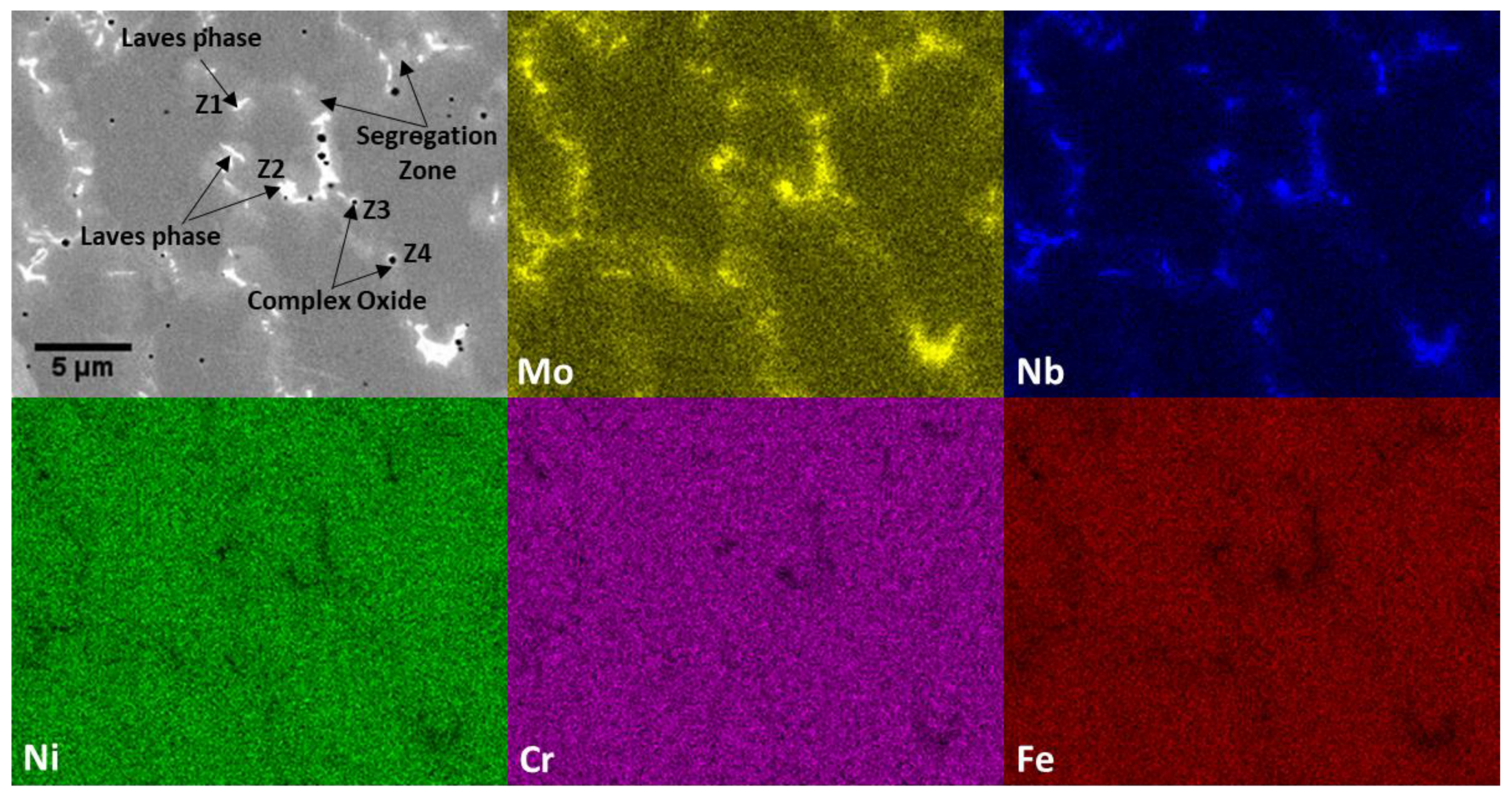
| Phases | Zones | Ni | Cr | Mo | Nb | Si | Fe | Mn | Al | Ca | C | O |
|---|---|---|---|---|---|---|---|---|---|---|---|---|
| Laves phase | Z1 | 42.16 | 17.39 | 10.97 | 10.88 | 3.17 | 15.43 | - | - | - | - | - |
| Z2 | 42.29 | 17.91 | 10.62 | 10.34 | 2.63 | 16.21 | - | - | - | - | - | |
| Oxide | Z3 | 0.33 | 4.24 | - | 1.11 | 13.00 | - | 2.44 | 15.83 | 4.70 | 2.58 | 55.77 |
| Z4 | 0.71 | 4.38 | - | 1.18 | 14.71 | - | 1.78 | 14.58 | 6.91 | - | 55.75 |
Publisher’s Note: MDPI stays neutral with regard to jurisdictional claims in published maps and institutional affiliations. |
© 2021 by the authors. Licensee MDPI, Basel, Switzerland. This article is an open access article distributed under the terms and conditions of the Creative Commons Attribution (CC BY) license (https://creativecommons.org/licenses/by/4.0/).
Share and Cite
Ferreira, A.A.; Amaral, R.L.; Romio, P.C.; Cruz, J.M.; Reis, A.R.; Vieira, M.F. Deposition of Nickel-Based Superalloy Claddings on Low Alloy Structural Steel by Direct Laser Deposition. Metals 2021, 11, 1326. https://doi.org/10.3390/met11081326
Ferreira AA, Amaral RL, Romio PC, Cruz JM, Reis AR, Vieira MF. Deposition of Nickel-Based Superalloy Claddings on Low Alloy Structural Steel by Direct Laser Deposition. Metals. 2021; 11(8):1326. https://doi.org/10.3390/met11081326
Chicago/Turabian StyleFerreira, André Alves, Rui Loureiro Amaral, Pedro Correia Romio, João Manuel Cruz, Ana Rosanete Reis, and Manuel Fernando Vieira. 2021. "Deposition of Nickel-Based Superalloy Claddings on Low Alloy Structural Steel by Direct Laser Deposition" Metals 11, no. 8: 1326. https://doi.org/10.3390/met11081326
APA StyleFerreira, A. A., Amaral, R. L., Romio, P. C., Cruz, J. M., Reis, A. R., & Vieira, M. F. (2021). Deposition of Nickel-Based Superalloy Claddings on Low Alloy Structural Steel by Direct Laser Deposition. Metals, 11(8), 1326. https://doi.org/10.3390/met11081326