Article

Numerical Simulation of a High-Speed Impact of Metal Plates Using a Three-Fluid Model

1
Department of Numerical Methods and Turbulence, Institute for Computer Aided Design of the Russian Academy of Sciences, 123056 Moscow, Russia
2
Department of Computational Physics, Moscow Institute of Physics and Technology, 141701 Dolgoprudny, Russia
*
Author to whom correspondence should be addressed.
Metals 2021, 11(8), 1233; https://doi.org/10.3390/met11081233
Submission received: 26 June 2021 / Revised: 27 July 2021 / Accepted: 30 July 2021 / Published: 3 August 2021
(This article belongs to the Special Issue Numerical Analysis of Welding and Processing)

Abstract

:
The process of wave formation at the contact boundary of colliding metal plates is a fundamental basis of explosive welding technology. In this case, the metals are in a pseudo-liquid state at the initial stages of the process, and from a mathematical point of view, a wave formation process can be described by compressible multiphase models. The work is devoted to the development of a three-fluid mathematical model based on the Baer–Nunziato system of equations and a corresponding numerical algorithm based on the HLL and HLLC methods, stiff pressure, and velocity relaxation procedures for simulation of the high-speed impact of metal plates in a one-dimensional statement. The problem of collision of a lead plate at a speed of 500 m/s with a resting steel plate was simulated using the developed model and algorithm. The problem statement corresponded to full-scale experiments, with lead, steel, and ambient air as three phases. The arrival times of shock waves at the free boundaries of the plates and rarefaction waves at the contact boundary of the plates, as well as the acceleration of the contact boundary after the passage of rarefaction waves through it, were estimated. For the case of a 3-mm-thick steel plate and a 2-mm-thick lead plate, the simulated time of the rarefaction wave arrival at the contact boundary constituted 1.05 μs, and it was in good agreement with the experimental value 1.1 μs. The developed numerical approach can be extended to the multidimensional case for modeling the instability of the contact boundary and wave formation in the oblique collision of plates in the Eulerian formalism.

1. Introduction

A significant number of studies have been devoted to the problem of a high-speed impact of metal plates, both from the point of view of fundamental issues of wave formation and the development of instability of the contact boundary [1,2,3], and from the practical point of view of optimizing the explosion welding process [4,5,6,7]. A historical overview of fundamental studies on the phenomenon of wave formation that occurs during the oblique high-speed impact of metal plates can be found in [1,2].
At the initial stage of the impact process, metals behave as immiscible pseudo-liquids [8], so it is appropriate to consider this problem using a heterogeneous media mechanics approach or a diffuse interface approach. There are few such studies available in the literature [9,10], and this paper is intended to partially fill this gap. The problem of high-speed impact of metal plates, in general, is at least a three-phase or three-fluid problem (material of one plate, material of another plate, ambient medium) when each phase is compressible, and its volume fraction ranges from zero to one. So, the diffuse interface models for the impact problem are generally based on the Baer–Nunziato (BN) system of equations [11], although other multiphase models can also be used [12,13]. There are two main classes of the three-fluid models for the BN equations that take their origin from the papers [14,15].
The multiphase nature of the process also makes it hard to study the development of the instability of the contact boundary in comparison with common single-phase phenomena. For example, one of the first models of wave formation during high-speed impact was proposed in [16]. The model considered the oblique interaction of a liquid jet with a moving surface covered with soft silicon putty, that is, actually the two-fluid model in the current terminology. As another example, in [17], the development of the Richtmayer–Meshkov instability was studied when a shock wave (SW) interacted with the contact surface, not between pure gas components, but with the curved interphase surface of a dense particle cloud.
It is worth noting that the problems of the high-speed collision were historically solved in the Lagrangian formalism, or, at least at some stage of the numerical algorithm, there was a Lagrangian stage [18]. In the diffuse interface methods within the framework of the Eulerian formalism, the key element is the calculation of parameters in the so-called “mixture cells”, in which various interacting materials are simultaneously present. In an early method of diffuse boundaries from [18], when describing the procedure for calculating parameters in “mixture cells”, the concept of the volume fraction of the phase was not introduced at all. The method was described as a set of heuristic numerical rules that operated with the donor and acceptor cells. The procedures for the stable calculation of “mixture cells” theoretically correspond to the stage of pressure relaxation procedure in the methods for solving the BN equations [9]. The Eulerian model can describe, for example, the generation of new interfaces without having to re-mesh the domain or at least destroy and create cells as in Lagrangian models [10]. The need to manipulate the computational grid complicates the use of Lagrangian techniques in the multidimensional case. It is the Eulerian methods that are of interest to us in this work because the further development of the methods of this work will be associated with the study of the instability of the interphase boundary, its possible significant deformations, which can create problems for Lagrangian methods due to the complexities of grid rearrangement. However, as was noted in [10], with the thickness of “the mixture region” being increased in time, the diffuse interface methods can only be used for short times. Hence, high-velocity processes (impacts, explosive phase transitions, etc.) are a natural application of such methods.
So, this paper continues our previous studies [19,20,21] and has two main goals. First, the goal is to develop a three-fluid model based on the BN system of equations and the computational algorithms Harten–Lax–van Leer (HLL) and Harten–Lax–van Leer-Contact (HLLC) (the latter method is particularly preferred because of much more accurate description of the interfacial boundaries) for the Eulerian simulation of the plates collision process. Secondly, the aim of the work is to qualitatively reproduce the main features of the full-scale experiment [8] on the high-speed normal impact of two metal plates. Note more recent studies on the planar impact of metal plates. For example, in [22], the collision of 0.4-mm-thick aluminum flyer plates with velocities of 600–700 m/s and aluminum samples with a thickness of 2.85–3 mm was considered. Our attention to the results from [8] was connected to the interesting and important mechanical effect of the development of interfacial boundary instability, reported in [8]. This effect is in close connection with the wave formation process underlying explosive welding technology.

2. Physical Statement of the Problem

We shall consider the interaction of a lead plate with the thickness hlead and initial density ρlead,0 = 11300 kg/m3 with a steel plate with the thickness hsteel and initial density ρsteel,0 = 7900 kg/m3. The lead plate is thrown in the direction of the steel one normal to the contact surface with a velocity of 500 m/s. Metal plates are surrounded by a layer of air 2 mm thick (Figure 1). It is assumed that at the initial stage of the impact during roughly the first 10 µs, the metals behave as pseudo-fluids [8] so the material of each plate can be considered as a compressible fluid (as well as the surrounding air) in a three-fluid BN-like model. With such a multiphase flow model, the same equations are solved everywhere with the same numerical scheme. This is achieved by adding a negligible quantity of the other phase in pure phases. The initial pressure is 105 Pa everywhere.

3. Mathematical Model

The mathematical model is based on the approach [14] and describes a flow of three immiscible compressible fluids:
U t + F x u = H U , α a i r x , α s t e e l x + P ,
U = α a i r α a i r ρ a i r α a i r ρ a i r v a i r α a i r ρ a i r E a i r α s t e e l α s t e e l ρ s t e e l α s t e e l ρ s t e e l v s t e e l α s t e e l ρ s t e e l E s t e e l α l e a d ρ l e a d α l e a d ρ l e a d v l e a d α l e a d ρ l e a d E l e a d ,   F = 0 α a i r ρ a i r v a i r α a i r ( ρ a i r v a i r 2 + p a i r ) α a i r v a i r ( ρ a i r E a i r + p a i r ) 0 α s t e e l ρ s t e e l v s t e e l α s t e e l ( ρ s t e e l v s t e e l 2 + p s t e e l ) α s t e e l v s t e e l ( ρ s t e e l E s t e e l + p s t e e l ) α l e a d ρ l e a d v l e a d α l e a d ( ρ l e a d v l e a d 2 + p l e a d ) α l e a d v l e a d ( ρ l e a d E l e a d + p l e a d ) ,
H = v i ( α a i r ) x 0 p i ( α a i r ) x p i v i ( α a i r ) x v i ( α s t e e l ) x 0 p i ( α s t e e l ) x p i v i ( α s t e e l ) x 0 p i ( α l e a d ) x p i v i ( α l e a d ) x ,   P = μ ( p a i r p l e a d ) 0 λ ( v l e a d v a i r ) λ v i ( v l e a d v a i r ) μ p i ( p a i r p l e a d ) μ ( p s t e e l p l e a d ) 0 λ ( v l e a d v s t e e l ) λ u i ( v l e a d v s t e e l ) μ p i ( p s t e e l p l e a d ) 0 λ ( v a i r v l e a d ) λ u i ( v a i r v l e a d ) μ p i ( p l e a d p a i r ) ,
α a i r + α s t e e l + α l e a d = 1 ,   E k = v k 2 2 + e k p k , ρ k = v k 2 2 + p k + γ k P 0 k ρ k γ k 1 ,
p i = k = 1 3 α k p k ,   v i = k = 1 3 α k ρ k v k / k = 1 3 α k ρ k .
Here U denotes the vector of “conservative” variables, F is the differential flux vector, H is the differential source term, and P is the algebraic source term, connected to the relaxation processes. The notation is conventional: t is the time, x is the spatial coordinate, α is the volume fraction, ρ is the true density, v is the velocity, p is the pressure, e is the specific internal energy, and E is the specific total energy. Parameters with indexes k = 1, 2, 3 correspond to the air, steel, and lead phases, respectively. Further, we use either these indexes or direct subscripts “air”, “steel”, and “lead” for clarity. Pressure and velocity with the “i” index correspond to the parameters at the fluid interfaces.
For each phase, the stiffened gas equation of state (EOS) with the parameters γ and P0 is used. In general, the properties of the metals EOS are extremely important for quantitatively and even qualitatively correct simulation of the characteristics of the impact process especially if the parameters of the impact imply, for instance, phase transitions. In [23], the hypervelocity impact problem was simulated using three different EOSs for lead that provided the effects of melting in strong SWs, evaporation in rarefaction waves (RW), and spallation. The specific features in the simulation results with the use of different EOSs were discussed. For the BN-type models, Mie–Gruneisen EOS (more general than stiffened gas EOS) can be applied [9,24,25] and the influence of this type of EOS on the simulation results is the subject of further study.
Parameter μ is responsible for pressure relaxation, and λ is for velocity relaxation. In the present work, we assume the instantaneous pressure and velocity equilibrium at the interface boundaries:
p a i r = p l e a d = p s t e e l ,
v a i r = v l e a d = v s t e e l .
Conditions (6) and (7) correspond to the stiff relaxation assumption μ→+∞, λ→+∞ [9,11] (see Section 4.3 and Section 4.4).

4. Numerical Algorithm

4.1. Splitting Scheme

The computational algorithm was based on the Strang splitting principle:
U j n + 1 = L p L v L h U j n .
We denote vector grid function by the same letter U as an unknown function in the defining system (1) – (5) but with the spatial index j and the time index n. At the hyperbolic stage of the algorithm denoted in (8) as operator Lh, the defining system of Equations (1)–(5) was solved with P = 0. After that, a velocity relaxation procedure Lv was implemented. Finally, a pressure relaxation procedure Lp was carried out. Consider each of the stages in more detail.

4.2. Hyperbolic Step

The computational domain was a one-dimensional segment, which was divided into N uniform cells. The size of the computational cell was Δx. Two approaches for the hyperbolic step were implemented, namely HLL and HLLC schemes.

4.2.1. HLL Method

Consider the HLL method for the three-fluid model first [9,14]. To begin with, the initial system (1)–(5) is formally divided into the first and fifth equations and the remaining sub-system:
u t + f x u = h u , α a i r x , α a i r x ,
u = α a i r ρ a i r α a i r ρ a i r v a i r α a i r ρ a i r E a i r α s t e e l ρ s t e e l α s t e e l ρ s t e e l v s t e e l α s t e e l ρ s t e e l E s t e e l α l e a d ρ l e a d α l e a d ρ l e a d v l e a d α l e a d ρ l e a d E l e a d ,   f = α a i r ρ a i r v a i r α a i r ( ρ a i r v a i r 2 + p a i r ) α a i r v a i r ( ρ a i r E a i r + p a i r ) α s t e e l ρ s t e e l v s t e e l α s t e e l ( ρ s t e e l v s t e e l 2 + p s t e e l ) α s t e e l v s t e e l ( ρ s t e e l E s t e e l + p s t e e l ) α l e a d ρ l e a d v l e a d α l e a d ( ρ l e a d v l e a d 2 + p l e a d ) α l e a d v l e a d ( ρ l e a d E l e a d + p l e a d ) ,   h = 0 p i ( α a i r ) x p i v i ( α a i r ) x 0 p i ( α s t e e l ) x p i v i ( α s t e e l ) x 0 p i ( α l e a d ) x p i v i ( α l e a d ) x .
Finite-volume approximations of the detached equations and the system (9), (10) are the following:
α k h , j n + 1 = α k j n Δ t n Δ x v i j n S j + 1 / 2 + α k j n S j + 1 / 2 α k j + 1 n + S j + 1 / 2 + S j + 1 / 2 α k j + 1 n α k j n S j + 1 / 2 + S j + 1 / 2 v i j n S j 1 / 2 + α k j 1 n S j 1 / 2 α k j n + S j 1 / 2 + S j 1 / 2 α k j n α k j 1 n S j 1 / 2 + S j 1 / 2 ,   k = 1 , 2 ,
u h , j n + 1 = u j n Δ t n Δ x f j + 1 / 2 u j n , u j + 1 n f j 1 / 2 u j n , u j + 1 n + h u j n , Δ α a i r x , Δ α s t e e l .
The numerical flux fj+1/2 in (12) is calculated using the HLL scheme:
f j + 1 / 2 u j n , u j + 1 n = S j + 1 / 2 + f u j n S j + 1 / 2 f u j + 1 n + S j + 1 / 2 + S j + 1 / 2 u j + 1 n u j n S j + 1 / 2 + S j + 1 / 2 ,
S j + 1 / 2 + = max k = 1 , 2 , 3 0 , v k j n + c k j n , v k j + 1 n + c k j + 1 n ,   S j + 1 / 2 = min k = 1 , 2 , 3 0 , v k j n c k j n , v k j + 1 n c k j + 1 n ,
where c is the speed of sound:
c k = γ k p k + P 0 k ρ k ,   k = 1 , 2 , 3 .
Spatial derivatives of αair and αsteel in the non-conservative term in (12) are approximated as:
Δ α k x = 1 Δ x S j + 1 / 2 + α k j n S j + 1 / 2 α k j + 1 n S j + 1 / 2 + S j + 1 / 2 S j 1 / 2 + α k j 1 n S j 1 / 2 α k j n S j 1 / 2 + S j 1 / 2 ,   k = 1 , 2 .
The latter approximation, consistent with the approximation of the divergent part of the system (9), (10) ensures the so-called “p-v” condition [26]. This condition claims that a multiphase system, uniform in velocity and pressure, should remain uniform through its evolution.
The time step is calculated dynamically from the condition:
Δ t n = CFL min k , j Δ x v k j n + c k j n ,
where CFL is a coefficient between 0 and 1.

4.2.2. HLLC Method

To improve the quality of simulations, the HLLC method from [27,28] was extended for the three-fluid model. From the general point of view, the methods in [27,28] are less accurate than later developments [24,25,29] because they are actually a straightforward generalization of the common HLLC for the Euler equations (meanwhile, the approximation of non-conservative differential terms and equations for the volume fractions evolution are of great importance) and do not use the elements of the Riemann problem solution for the BN equations. However, the methods in [27,28] are much easier to implement and to extend to the three-fluid case.
Again as for the HLL method (11)–(17), we shall consider approximations of the first and the fifth equations of the system (1) and sub-system (9). Equations of volume fraction evolution are approximated as:
α k h , j n + 1 = α k j n Δ t n Δ x φ k , j + 1 / 2 φ k , j 1 / 2 ,   k = 1 , 2 ,
φ k , j + 1 / 2 = α k j n ,   if   v i j n 0 , α k j + 1 n ,   else .
The general finite-volume scheme (12) for the sub-system (9), (10) remains the same. The numerical flux fj+1/2 is calculated using the HLLC scheme:
f j + 1 / 2 u j n , u j + 1 n = f u j n ,   if   S j + 1 / 2 0 , f u j n + S j + 1 / 2 q j n u j n ,   if   S j + 1 / 2 < 0 and S j + 1 / 2 * 0 , f u j + 1 n + S j + 1 / 2 + q j + 1 n u j + 1 n ,   if   S j + 1 / 2 * < 0 and S j + 1 / 2 + 0 , f u j + 1 n ,   if   S j + 1 / 2 + 0 .
S j + 1 / 2 + = max k = 1 , 2 , 3 v k j n + c k j n , v k j + 1 n + c k j + 1 n ,   S j + 1 / 2 = min k = 1 , 2 , 3 v k j n c k j n , v k j + 1 n c k j + 1 n ,
S j + 1 / 2 * = p i j + 1 n p i j n + ρ i j n v i j n S j + 1 / 2 v i j n ρ i j + 1 n v i j + 1 n S j + 1 / 2 + v i j + 1 n ρ i j n S j + 1 / 2 v i j n ρ i j + 1 n S j + 1 / 2 + v i j + 1 n ,
ρ i = α k ρ k ,
q j n = q j , a i r n q j , s t e e l n q j , l e a d n ,   q j + 1 n = q j + 1 , a i r n q j + 1 , s t e e l n q j + 1 , l e a d n ,
q j , k n = C j , k C j , k S j + 1 / 2 * C j , k p k j n / ρ k j n + S j + 1 / 2 * v k j n S j + 1 / 2 * + p k j n / ρ k j n / S j + 1 / 2 v k j n ,   k = 1 , 2 , 3 ,
q j + 1 , k n = C j + 1 , k C j + 1 , k S j + 1 / 2 * C j + 1 , k p k j + 1 n / ρ k j + 1 n + S j + 1 / 2 * v k j + 1 n S j + 1 / 2 * + p k j + 1 n / ρ k j + 1 n / S j + 1 / 2 + v k j + 1 n ,   k = 1 , 2 , 3 ,
C j , k = α k j n S j + 1 / 2 v a i r j n S j + 1 / 2 S j + 1 / 2 * ,   C j + 1 , k = α k j + 1 n S j + 1 / 2 + v a i r j + 1 n S j + 1 / 2 + S j + 1 / 2 * ,   k = 1 , 2 , 3 .
Spatial derivatives of αair and αsteel in the non-conservative term in (12) are approximated as:
Δ α k x = 1 Δ x ψ k , j + 1 / 2 ψ k , j 1 / 2 ,   k = 1 , 2 ,
ψ k , j + 1 / 2 = α k j n ,   if   S j + 1 / 2 * 0 , α k j + 1 n ,   else .
Simulations in Section 5 below show that the HLLC method (18)–(29) was less robust than the HLL one. The initial volume fraction of air αair, i.e., the small parameter, in the regions that corresponded to the steel and lead plates, and in the HLLC simulations, should be tuned more carefully than in the HLL simulations. For example, the HLLC simulation failed if αair was equal to 10–6.

4.3. Velocity Relaxation

For the velocity relaxation, the following system of ordinary differential equations (ODE) for each phase k = 1, 2, 3 is solved in each computational cell [14]:
α k t = 0 , ( α k ρ k ) t = 0 , ( α k ρ k v k ) t = λ v m v k , ( α k ρ k E k ) t = λ u i v m v k ,
where m is any index not equal to k. To achieve velocity equilibrium (7), the relaxation coefficient λ in (30) is assumed to tend to infinity. Such a proposal leads to the equation for equilibrium velocity:
v ¯ = k ( α k ρ k v k ) 0 k ( α k ρ k ) 0 ,
where index “0” denotes values obtained after the hyperbolic step. After that, the specific internal energy correction is required for each phase:
e k = e k , 0 + 1 2 v ¯ v k , 0 2 .
As the true densities of the phases do not change during velocity relaxation (as well as volume fractions), the correction of the internal energies (32) leads to the correction of phase pressures only.

4.4. Pressure Relaxation

At the pressure relaxation step, it is required to solve the following ODE system for each phase in each computational cell [14]:
α k t = μ p k p m , α k ρ k t = 0 , α k ρ k v k t = 0 , α k ρ k E k t = μ p i p k p m ,
where m is again any index not equal to k. The pressure relaxation procedure follows the same principle as velocity relaxation. When the relaxation parameter μ in (33) tends to infinity, all pressures after relaxation must be equal. Combining the volume fraction, mass, momentum, and energy equation, we get [14]
e k t = p i t 1 ρ k .
Trapezoidal approximation of (34) gives:
e ¯ k e k 0 = 1 2 p ¯ + p i 0 1 ρ ¯ k 1 ρ k 0 ,
where index “0” denotes values obtained after the velocity relaxation procedure, and values with bars are the relaxed ones. So, using the EOS for each phase, saturation constraint α 1 + α 2 + α 3 = 1 and Formula (35) it is possible to obtain a system of non-linear equation for variables ρ ¯ a i r , ρ ¯ s t e e l , ρ ¯ l e a d , p ¯ :
{ 2 ρ ¯ a i r ρ a i r 0 p ¯ + γ a i r P 0 a i r ρ ¯ a i r γ a i r 1 p a i r 0 + γ a i r P 0 a i r ρ a i r 0 γ a i r 1 p ¯ + p i 0 ρ ¯ a i r ρ a i r 0 = 0 , 2 ρ ¯ s t e e l ρ s t e e l 0 p ¯ + γ s t e e l P 0 s t e e l ρ ¯ s t e e l γ s t e e l 1 p s t e e l 0 + γ s t e e l P 0 s t e e l ρ s t e e l 0 γ s t e e l 1 p ¯ + p i 0 ρ ¯ s t e e l ρ s t e e l 0 = 0 , 2 ρ ¯ l e a d ρ l e a d 0 p ¯ + γ l e a d P 0 l e a d ρ ¯ l e a d γ l e a d 1 p l e a d 0 + γ l e a d P 0 l e a d ρ l e a d 0 γ l e a d 1 ( p ¯ + p i 0 ) ( ρ ¯ l e a d ρ l e a d 0 ) = 0 , m k / ρ ¯ k 1 = 0 ,
m k = α k 0 ρ k 0 .
In the two-phase case, the analogous system can be reduced to one quadratic equation that can be solved analytically [30,31]. In the current case, as in the case of more complicated equilibrium conditions (for example, taking into account intergranular stresses in the gas—particles simulations [32]), the non-linear system (36)–(37) should be solved:
F X = 0 ,
X = ρ ¯ a i r ρ ¯ s t e e l ρ ¯ l e a d p ¯ ,   F X = [ 2 ρ ¯ a i r ρ a i r 0 p ¯ + γ a i r P 0 a i r ρ a i r γ a i r 1 p a i r 0 + γ a i r P 0 a i r ρ a i r 0 γ a i r 1 p ¯ + p i 0 ρ ¯ a i r ρ a i r 0 2 ρ ¯ s t e e l ρ s t e e l 0 p ¯ + γ s t e e l P 0 s t e e l ρ s t e e l γ s t e e l 1 p s t e e l 0 + γ s t e e l P 0 s t e e l ρ s t e e l 0 γ s t e e l 1 p ¯ + p i 0 ρ ¯ s t e e l ρ s t e e l 0 2 ρ ¯ l e a d ρ l e a d 0 p ¯ + γ l e a d P 0 l e a d ρ l e a d γ l e a d 1 p l e a d 0 + γ l e a d P 0 l e a d ρ l e a d 0 γ l e a d 1 p ¯ + p i 0 ρ ¯ l e a d ρ l e a d 0 m k / ρ ¯ k 1 ]
The solution of the system (38) – (39) is obtained with the Newton–Raphson method:
X s + 1 = X s J 1 X s F X s ,
J X = F X = A a i r 0 0 B a i r 0 A s t e e l 0 B s t e e l 0 0 A l e a d B l e a d m a i r / ρ ¯ a i r 2 m s t e e l / ρ ¯ s t e e l 2 m l e a d / ρ ¯ l e a d 2 0 ,
A k = 2 p k 0 + γ k P 0 k γ k 1 p ¯ + p i 0 ,   B k = 2 ρ k 0 γ k 1 ρ ¯ k + ρ k 0 ,   k = 1 , 2 , 3 ,
where s is a current iteration number in the repetitive process (40)–(42).

5. Simulation Results

To obtain quantitatively valid characteristics of the collision process, the parameters of the stiffened-gas equations of state for the fluids in consideration must be calibrated using either experimental data or the data computed using the real-life wide range metal EOS. Parameters of the EOS for steel and lead were taken close to those found in our previous works [19,20]. Parameters were obtained by comparing the computed characteristics of the SWs formed at collision with the computed data obtained by the procedure described in [33], which used the wide range EOS for metals [34] (this procedure was implemented in [35]). We took γ = 3.0 and P0 = 65.0 GPa for steel; and γ = 2.7 and P0 = 15.5 GPa for lead. The maximal relative differences in SWs speed, pressure, and velocity at the contact surface and the densities behind the SW fronts in our simulations do not exceed 7% in comparison with the reference values. For air, the values γ = 1.4 and P0 = 0 were used.
Simulations were carried out with a spatial resolution of 2.5 μm. For example, a plate with a thickness of 2 mm was resolved with the use of 800 computational cells. The CFL number in (17) was equal to 0.5. We set the non-penetrating condition on both boundaries of the computational area.
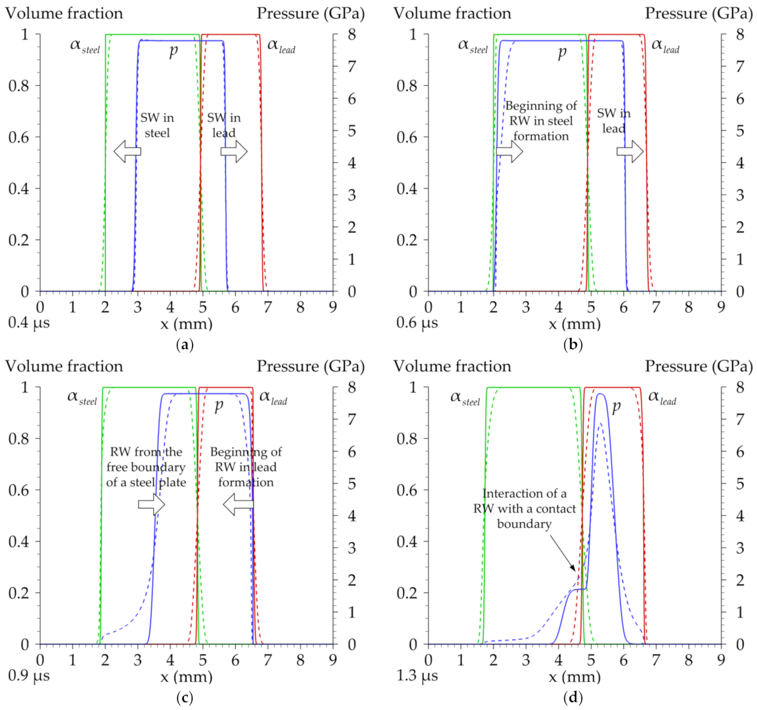
Consider the main stages of the process for the case of hsteel = 3 mm, hlead = 2 mm. Figure 2 illustrates spatial distributions of metals’ volume fractions and pressure. The initial impact causes the formation of two SWs propagating in the opposite directions towards the free surfaces of the plates (see Figure 2a). At a time instant of about τsteel = 0.6 μs after the beginning of plates interaction, SW in steel reaches a free boundary (see Figure 2b). As a result of an SW interaction with a free boundary of the plate, RW forms. It moves towards the interface between colliding plates (see Figure 2c). At a time instant of about Tsteel = 1.1 μs, RW from steel reaches the interface and moves through it (see Figure 2d). Analogous processes occur in the lead plate. The times τsteel, τlead, Tsteel, and Tlead depend on the thicknesses of the plates. In the considered case, RW from the free boundary of the steel plate reaches the interface boundary between the plates faster than the RW from the free boundary of the lead plate. As is seen from Figure 2d, an RW from the steel plate interacts with a high-pressure region in the lead plate and the time instant Tlead has no sense in this case. As a result of an RW passing, the interface accelerates rapidly in the direction of a free boundary of the steel plate. This acceleration together with the density gradient in the opposite direction can cause a development of the Rayleigh–Taylor instability of the interface. This question was studied in [21] using three-dimensional Euler equations.
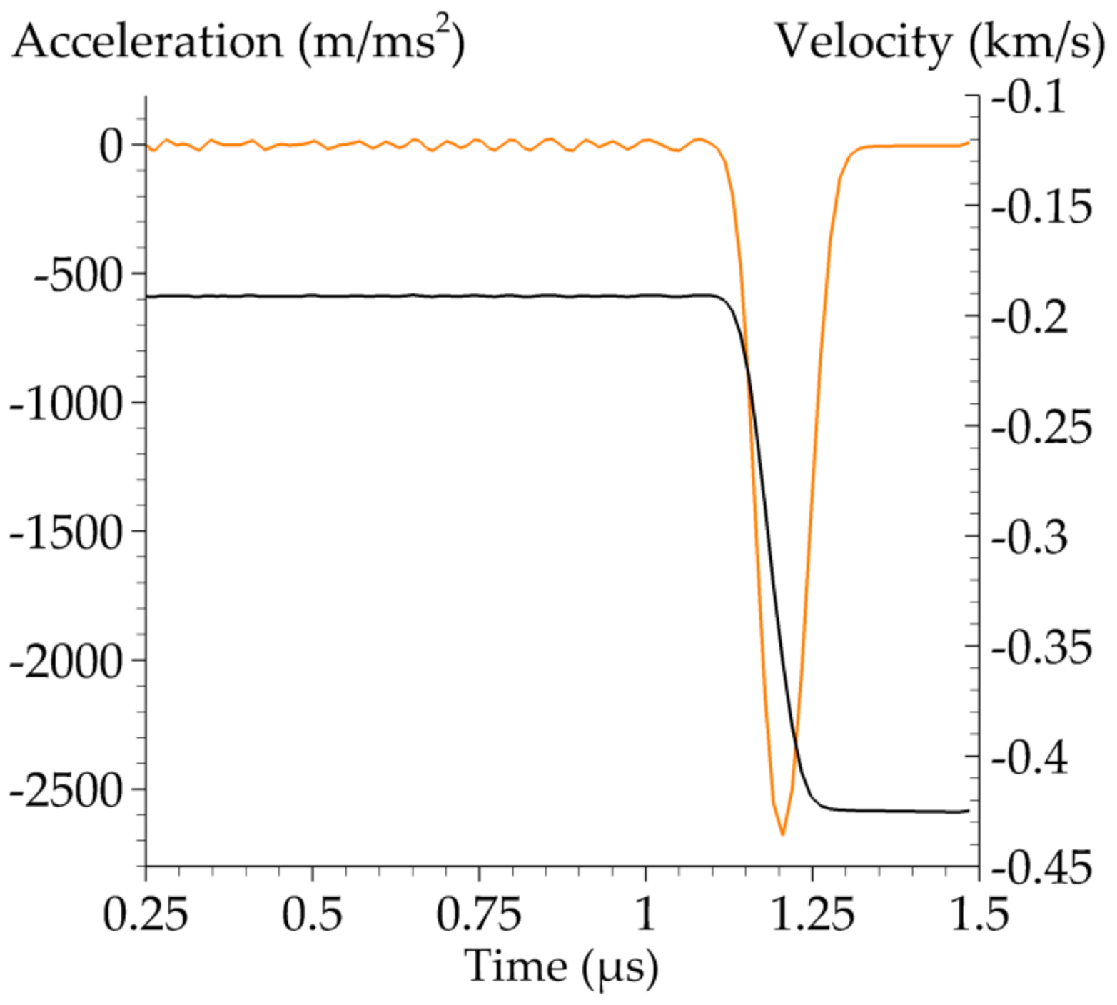
Figure 3 illustrates the dynamics of the velocity and the acceleration of the interface boundary between the plates. Both plots were obtained by numerical differentiation of the dependency x1/2-t, where x1/2 is a “center” of the diffuse interface between the plates (the coordinate of the computational cell center, where αsteel = αlead 1/2 are accurate within the existence of a small amount of air, αair 10–5). The smooth region on the black curve between time instants of about 1.1 μs and 1.3 μs corresponds to the acceleration of the interfacial boundary between the plates due to the RW arrival. The interfacial boundary speed increased from about 195 m/s up to 425 m/s. The orange curve at the same time interval demonstrates a pronounced peak. Trembling of the acceleration curve up to about 1.1 μs has a numerical nature. It vanishes at the later time instants with the increase of the interface boundary speed after the RW passing and thus with the decrease of the effect of uncertainty of the x1/2 definition due to the spatial discretization of the computational domain. Figure 3 gives quantitative estimations of the realized acceleration and the time of its action. These data can be used for the estimations of the possibility of the Rayleigh–Taylor instability development of the interfacial boundary. After the meeting of two RWs from the free boundaries of the plates after about 1.5 μs, the simulation crashed because of a negative pressure occurrence. The problem was not due to the numerical instability but rather due to going beyond the limits of applicability of the gas-dynamics model of the process in use. Large tensile forces that can lead to the formation of internal cracks in the physical experiment demand the usage of models like [10] at the following stages of the process of plates’ collision.
Following experiments [8], parametric simulations were performed for various thicknesses of a steel plate. The results in terms of time instants τ and T are presented in Table 1. In this series of simulations, the HLL scheme was used as the results in terms of time instants τ and T were close for both HLL and HLLC methods. The second row in the table corresponds to the problem statement considered above (see Figure 2). A label “–” instead of the T value means that an RW from another plate reached the interfacial boundary first. A label “×” means that a time instant could not be measured because of the simulation crash after two RWs meeting. For a small thickness of the steel plate (up to 4 mm), the dynamics of the interfacial boundary motion is determined by an RW from the steel plate side. For hsteel = 4.5 mm, time instants τsteel and τlead become almost equal. With the following increase of the hsteel, the process is determined by an RW from the lead plate. The experimental value of Tsteel for simulation No. 2 is available and constitutes 1.1 μs [8]. The calculated value is 1.05 μs and it is very close to the experimental one.

6. Discussion

Let us compare the results of simulations using the HLL scheme (11)–(17) and the HLLC scheme (18)–(29) on the hyperbolic step. Figure 2a shows that SWs in both simulations are described almost identically. As expected, maximal differences were obtained in the description of the interfacial boundaries—between two plates and between free surfaces of the plates and ambient air. The non-moving free surface of the steel plate up to the moment of the SW arrival was not smeared at all in the HLLC simulation (see Figure 2a). This important property, valid for the HLLC method for the Euler equations solution, was inherited by the HLLC method for the BN equations [27,28]. Moving interfacial boundaries are smeared by both HLL and HLLC methods, but the HLL diffuse interface is an order of magnitude greater than the HLLC diffusive interface. Apparently, it is one of the reasons that the RW that occurs after SW arrives at the free boundary of the plate is described in the simulation using the HLL scheme with very large errors, compared with the HLLC approach. The pressure to the left of the tail of the RW in steel in Figure 2c,d does not fall to 1 atm in the HLL simulation. The RW is not localized with a long non-physical tail. On the contrary, the RW in the HLLC simulation has a profile close to the SW, which is typical for wave processes in condensed media.
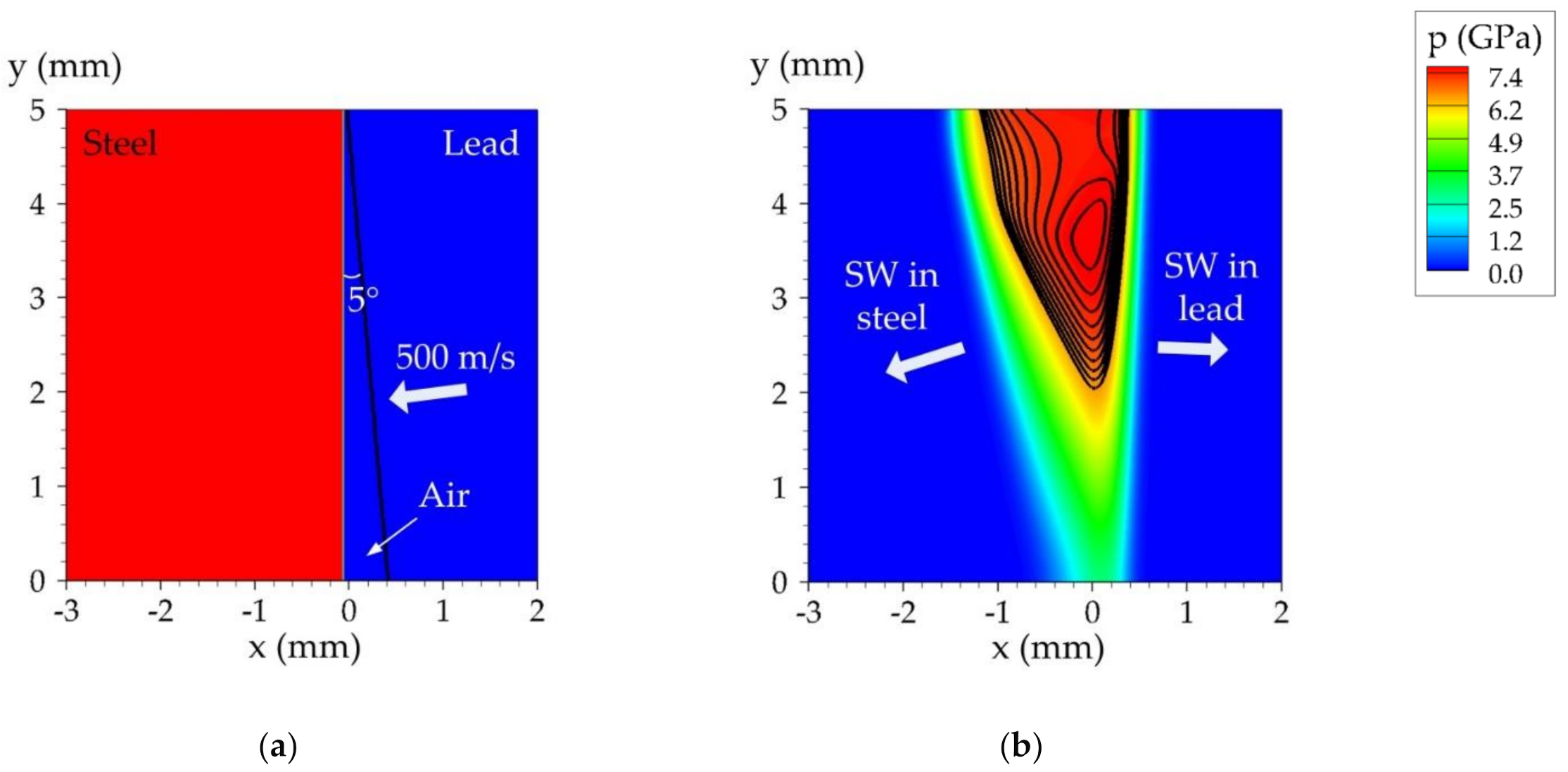
Our further goal was to develop a two- and three-dimensional algorithm for studying the development of the instability of the interfacial boundary of the metal plates during oblique collision using a three-fluid model. The developed one-dimensional model of the process and the computational algorithm allows such extensions, for example, using a multidimensional algorithm from [14]. A two-dimensional three-fluid HLL approach was realized. Figure 4 demonstrates preliminary statement and simulation results for the problem of the oblique impact of the plates. The initial velocity of the lead plate was equal to 500 m/s and was directed normally to its surface (see Figure 4a). The initial angle between the surfaces of the plates was equal to 5°. All boundaries were free. The computational grid was uniform with a cell size equal to 10–2 mm. Figure 4b demonstrates non-planar SWs, originating after an oblique impact, and the very beginning of the wave formation process at the interfacial boundary between the plates. The major problem we have faced in the two-dimensional simulation was the motion of the air in the gap between the plates being too fast due to the velocity relaxation procedure (30)–(32). Apparently, this part of the model was not very relevant to the real process in the multi-dimensional case. Note the up-to-date studies of such types of flow due to the body impact [36,37]. It was reported in [36] that the flow between a base and a cladding plate can affect the process of explosive welding. Further multi-dimensional simulations require the use of the HLLC scheme, at least an order of magnitude more detailed computational grids, and, probably, another problem formulation with the resolution of the angle of the lead plate for a more correct description of the dynamics of the contact point between the plates.

7. Conclusions

Thus, we adapted a multiphase model [14] from the class of diffuse interface approaches for the consideration of the problem of a high-speed collision of metal plates, which is a theoretical foundation for the problem of explosive welding. In addition to the common HLL method for solving BN equations [9], we adapted the HLLC method [27,28] for the three-phase case, which showed qualitatively better results than the HLL method. Nowadays, the most developed numerical approaches for the high-speed impact simulations include Arbitrary Lagrangian–Eulerian (ALE) methods [38], molecular dynamics methods [39,40], and smoothed particle hydrodynamics (SPH) methods [3,38]. As noticed in [38], a traditional pure Lagrangian analysis, such as in [1], is not able to accurately model the impact process due to excessive computational cells or elements in the finite element analysis (FEA) distortion near the contact zone. However, generally, the SPH method is less accurate than the pure Lagrangian FEA method especially when the deformation is not severe. However, only using the SPH method, in contrast to ALE, the authors of [38] focused on the jetting phenomenon (regarding a jet moving ahead of the collision point during the oblique impact of the plates) and the composition of the jetted material able to be simulated. These conclusions were confirmed in [3] where SPH simulations in Ansys Autodyn allowed authors to accurately reproduce the formation of the wave boundary, vortex zones, as well as the formation of a jet moving ahead of the collision point in the oblique impact of metal plates. In [39,40], the wave formation process during explosive welding was carried out using a LAMMPS molecular dynamics simulator. Apparently, the molecular dynamics method is the most physically relevant one, but the size of the bodies simulated by the molecular dynamics method is 4–5 orders of magnitude less than the size of the plates that are used in explosive welding experiments [40]. Additional scaling procedures should be used. So, in this paper, we studied the principal possibility of the simulation of the impact of the plates using the shock-capturing, algorithmically uniform, and thus attractive Eulerian three-phase diffuse interface method.
The proposed approach was applied to the problem of a planar impact of steel and lead plates of different thicknesses. The problem follows previous experimental studies [8]. The dynamics of shock and rarefaction waves in the samples were analyzed. Quantitative estimation of the acceleration of the interfacial boundary due to the passage of the rarefaction wave from a free boundary of one of the plates was obtained. For the case of the 3-mm-thick steel plate and the 2-mm-thick lead plate, the simulated time of the rarefaction wave arrival at the contact boundary constituted 1.05 μs, and it was in good agreement with the experimental value of 1.1 μs.
The preliminary results of the two-dimensional simulation of the oblique impact of the metal plates using the proposed approach are presented. The results are encouraging from the point of view of subsequent simulation of the wave formation process during the oblique impact.

Author Contributions

Conceptualization, P.U. and S.F.; methodology, P.U.; software, P.C. and P.U.; validation, P.C.; formal analysis, P.U. and S.F.; investigation, P.C., P.U., and S.F.; resources, P.U. and S.F.; data curation, P.U.; writing—original draft preparation, P.C., P.U., and S.F.; writing—review and editing, P.U. and S.F.; visualization, P.C. and P.U.; supervision, P.U. and S.F.; project administration, S.F.; funding acquisition, S.F. All authors have read and agreed to the published version of the manuscript.

Funding

This work was supported by the Russian Science Foundation, project no. 17-11-01293-P.

Institutional Review Board Statement

Not applicable.

Informed Consent Statement

Not applicable.

Data Availability Statement

Data sharing not applicable.

Conflicts of Interest

The authors declare no conflict of interest.

Nomenclature

α volume fraction μ pressure relaxation parameter
ρ density λ velocity relaxation parameter
v velocityairsubscript for the air parameters
p pressuresteelsubscript for the steel parameters
E specific total energyleadsubscript for the lead parameters
e specific internal energyisubscript for the interfacial parameters

References

  1. Godunov, S.; Deribas, A.; Zabrodin, A.; Kozin, N. Hydrodynamic effects in colliding solids. J. Comput. Phys. 1970, 5, 517–539. [Google Scholar] [CrossRef]
  2. Deribas, A. Physics of Hardening and Welding by Explosion; Nauka: Novosibirsk, Russia, 1972. [Google Scholar]
  3. Bataev, I.; Tanaka, S.; Zhou, Q.; Lazurenko, D.; Junior, A.J.; Hokamoto, K.; Mori, A.; Chen, P. Towards better understanding of explosive welding by combination of numerical simulation and experimental study. Mater. Des. 2019, 169, 107649. [Google Scholar] [CrossRef]
  4. Kaya, Y. Investigation of Copper-Aluminium Composite Materials Produced by Explosive Welding. Metals 2018, 8, 780. [Google Scholar] [CrossRef] [Green Version]
  5. Wang, H.; Wang, Y. High-Velocity Impact Welding Process: A Review. Metals 2019, 9, 144. [Google Scholar] [CrossRef] [Green Version]
  6. Carvalho, G.H.S.F.L.; Galvão, I.; Mendes, R.; Leal, R.M.; Loureiro, A. Aluminum-to-Steel Cladding by Explosive Welding. Metals 2020, 10, 1062. [Google Scholar] [CrossRef]
  7. Malakhov, A.Y.; Saikov, I.V.; Denisov, I.V.; Niyezbekov, N.N. AlMg6 to Titanium and AlMg6 to Stainless Steel Weld Interface Properties after Explosive Welding. Metals 2020, 10, 1500. [Google Scholar] [CrossRef]
  8. Yakovlev, I.V. Instability of the interface between colliding metals. Combust. Explos. Shock. Waves 1975, 9, 390–393. [Google Scholar] [CrossRef]
  9. Saurel, R.; Abgrall, R. A Multiphase Godunov Method for Compressible Multifluid and Multiphase Flows. J. Comput. Phys. 1999, 150, 425–467. [Google Scholar] [CrossRef]
  10. Favrie, N.; Gavrilyuk, S. Diffuse interface model for compressible fluid—Compressible elastic–plastic solid interaction. J. Comput. Phys. 2012, 231, 2695–2723. [Google Scholar] [CrossRef]
  11. Baer, M.; Nunziato, J. A two-phase mixture theory for the deflagration-to-detonation transition (ddt) in reactive granular materials. Int. J. Multiph. Flow 1986, 12, 861–889. [Google Scholar] [CrossRef]
  12. Zeidan, D.; Bähr, P.; Farber, P.; Gräbel, J.; Ueberholz, P. Numerical investigation of a mixture two-phase flow model in two-dimensional space. Comput. Fluids 2019, 181, 90–106. [Google Scholar] [CrossRef]
  13. Goncalves, E.; Hoarau, Y.; Zeidan, D. Simulation of shock-induced bubble collapse using a four-equation model. Shock. Waves 2018, 29, 221–234. [Google Scholar] [CrossRef] [Green Version]
  14. Saurel, R.; Lemetayer, O. A multiphase model for compressible flows with interfaces, shocks, detonation waves and cavitation. J. Fluid Mech. 2001, 431, 239–271. [Google Scholar] [CrossRef]
  15. Hérard, J.-M. A three-phase flow model. Math. Comput. Model. 2007, 45, 732–755. [Google Scholar] [CrossRef] [Green Version]
  16. Abrahamson, G.R. Permanent Periodic Surface Deformations Due to a Traveling Jet. J. Appl. Mech. 1961, 28, 519–528. [Google Scholar] [CrossRef]
  17. Meng, B.; Zeng, J.; Tian, B.; Li, L.; He, Z.; Guo, X. Modeling and verification of the Richtmyer–Meshkov instability linear growth rate of the dense gas-particle flow. Phys. Fluids 2019, 31, 074102. [Google Scholar] [CrossRef]
  18. Mader, C.L. Numerical Modeling of Explosives and Propellants; CRC Press: Boca Raton, FL, USA, 2008. [Google Scholar]
  19. Utkin, P.S.; Fortova, S.V. Mathematical modeling of impact of two metal plates using two-fluid approach. J. Phys. Conf. Ser. 2018, 946, 012047. [Google Scholar] [CrossRef]
  20. Utkin, P.S.; Fortova, S.V. Mathematical Modeling of High-Speed Interaction of Metallic Plates within the Two-Fluid Euler Approach. Comput. Math. Math. Phys. 2018, 58, 1377–1383. [Google Scholar] [CrossRef]
  21. Fortova, S.V.; Utkin, P.S.; Kazakova, T.S. Three-Dimensional Numerical Simulation of the Development of Instability of a Contact Boundary of Colliding Metal Plates within the Gas-Dynamic Approximation. High Temp. 2019, 57, 236–241. [Google Scholar] [CrossRef]
  22. Kanel, G.I.; Razorenov, S.; Baumung, K.; Singer, J. Dynamic yield and tensile strength of aluminum single crystals at temperatures up to the melting point. J. Appl. Phys. 2001, 90, 136–143. [Google Scholar] [CrossRef]
  23. Povarnitsyn, M.; Khishchenko, K.; Levashov, P. Hypervelocity impact modeling with different equations of state. Int. J. Impact Eng. 2006, 33, 625–633. [Google Scholar] [CrossRef]
  24. Lochon, H.; Daude, F.; Galon, P.; Hérard, J.-M. HLLC-type Riemann solver with approximated two-phase contact for the computation of the Baer–Nunziato two-fluid model. J. Comput. Phys. 2016, 326, 733–762. [Google Scholar] [CrossRef] [Green Version]
  25. Hennessey, M.; Kapila, A.; Schwendeman, D. An HLLC-type Riemann solver and high-resolution Godunov method for a two-phase model of reactive flow with general equations of state. J. Comput. Phys. 2020, 405, 109180. [Google Scholar] [CrossRef]
  26. Abgrall, R. How to Prevent Pressure Oscillations in Multicomponent Flow Calculations: A Quasi Conservative Approach. J. Comput. Phys. 1996, 125, 150–160. [Google Scholar] [CrossRef] [Green Version]
  27. Qiang, L.; Jian-Hu, F.; Ti-Min, C.; Chun-Bo, H. Difference scheme for two-phase flow. Appl. Math. Mech. 2004, 25, 536–545. [Google Scholar] [CrossRef]
  28. Liang, S.; Liu, W.; Yuan, L. Solving seven-equation model for compressible two-phase flow using multiple GPUs. Comput. Fluids 2014, 99, 156–171. [Google Scholar] [CrossRef]
  29. Furfaro, D.; Saurel, R. A simple HLLC-type Riemann solver for compressible non-equilibrium two-phase flows. Comput. Fluids 2015, 111, 159–178. [Google Scholar] [CrossRef]
  30. Utkin, P.S. Mathematical Modeling of the Interaction of a Shock Wave with a Dense Cloud of Particles within the Framework of the Two-Fluid Approach. Russ. J. Phys. Chem. B 2017, 11, 963–973. [Google Scholar] [CrossRef]
  31. Utkin, P. Numerical simulation of shock wave—Dense particles cloud interaction using Godunov solver for Baer–Nunziato equations. Int. J. Numer. Methods Heat Fluid Flow 2019, 29, 3225–3241. [Google Scholar] [CrossRef]
  32. Poroshyna, Y.; Utkin, P. Numerical simulation of a normally incident shock wave—Dense particles layer interaction using the Godunov solver for the Baer–Nunziato equations. Int. J. Multiph. Flow 2021, 142, 103718. [Google Scholar] [CrossRef]
  33. Fortov, V.; Kim, V.; Lomonosov, I.; Matveichev, A.; Ostrik, A. Numerical modeling of hypervelocity impacts. Int. J. Impact Eng. 2006, 33, 244–253. [Google Scholar] [CrossRef]
  34. Fortov, V.; Khishchenko, K.; Levashov, P.; Lomonosov, I. Wide-range multi-phase equations of state for metals. Nucl. Instrum. Methods Phys. Res. Sect. A 1998, 415, 604–608. [Google Scholar] [CrossRef]
  35. Shock Wave Database. Available online: http://www.ihed.ras.ru/rusbank/ (accessed on 22 June 2021).
  36. Li, X.; Wang, Y.; Wang, X.; Yan, H.; Zeng, X.; Wang, J. Gas shock waves in the gap between the base and cladding plates during explosive welding. Explos. Shock. Waves 2021, 41, 075301. [Google Scholar] [CrossRef]
  37. Skews, B.W.; Ndebele, B. Fluid Dynamics Associated with Body Impact. J. Appl. Fluid Mech. 2021, 14, 993–1002. [Google Scholar] [CrossRef]
  38. Nassiri, A.; Kinsey, B. Numerical studies on high-velocity impact welding: Smoothed particle hydrodynamics (SPH) and arbitrary Lagrangian–Eulerian (ALE). J. Manuf. Process. 2016, 24, 376–381. [Google Scholar] [CrossRef] [Green Version]
  39. Kiselev, S.P.; Mali, V.I. Numerical and experimental modeling of jet formation during a high-velocity oblique impact of metal plates. Combust. Explos. Shock. Waves 2012, 48, 214–225. [Google Scholar] [CrossRef]
  40. Godunov, S.K.; Kiselev, S.P.; Kulikov, I.M.; Mali, V. Numerical and experimental simulation of wave formation during explosion welding. Proc. Steklov Inst. Math. 2013, 281, 12–26. [Google Scholar] [CrossRef]
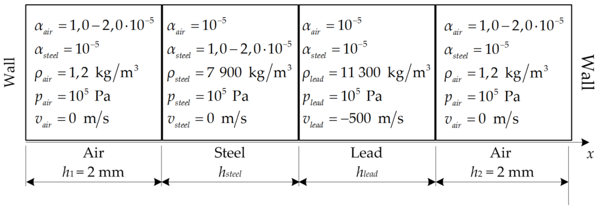
Figure 1. Schematic of the problem about a high-speed normal impact of two metal plates.
Metals 11 01233 g001
Figure 2. Predicted spatial distributions of αsteel (green color), αlead (red color), and p (blue color) at the successive time moments: (a) 0.4 μs, (b) 0.6 μs, (c) 0.9 μs, (d) 1.3 μs; hsteel = 3 mm, hlead = 2 mm. Dashed lines correspond to the HLL simulation, solid lines correspond to the HLLC simulation.
Metals 11 01233 g002
Figure 3. Predicted velocity (black curve) and acceleration (orange curve) of the contact boundary between metal plates; hsteel = 3 mm, hlead = 2 mm; simulation using the HLLC method.
Metals 11 01233 g003
Figure 4. Preliminary two-dimensional simulation of the oblique impact: (a) Schematic of the problem; (b) predicted spatial distribution of pressure and steel density isolines, time instant 0.3 μs.
Metals 11 01233 g004
Table 1. Times of arrival of an SW to the free boundary of a plate (τ) and arrival of an RW to the interfacial boundary between the plates (T) for the steel and lead plates; hlead = 2 mm; simulations using the HLL method.
No.hsteel, mmτsteel, μsτlead, μsTsteel, μsTlead, μs
120.380.80.70
230.541.05
340.721.381.38
44.50.821.38
550.911.38
6101.851.38
720×1.38
Publisher’s Note: MDPI stays neutral with regard to jurisdictional claims in published maps and institutional affiliations.