
Mechanical and Microstructural Properties of A36 Marine Steel Subjected to Underwater Wet Welding


Abstract
1. Introduction
2. Materials and Methods
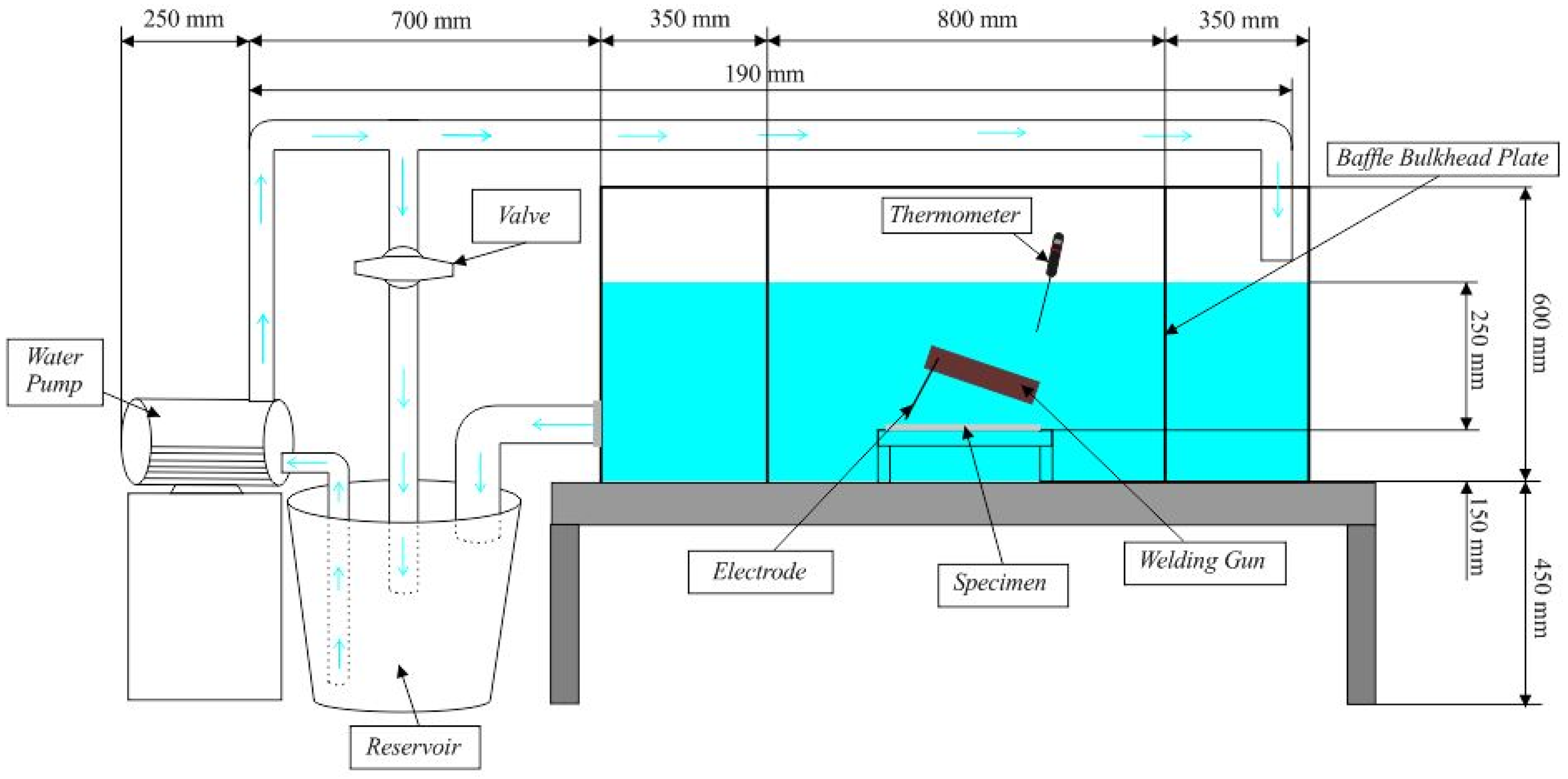
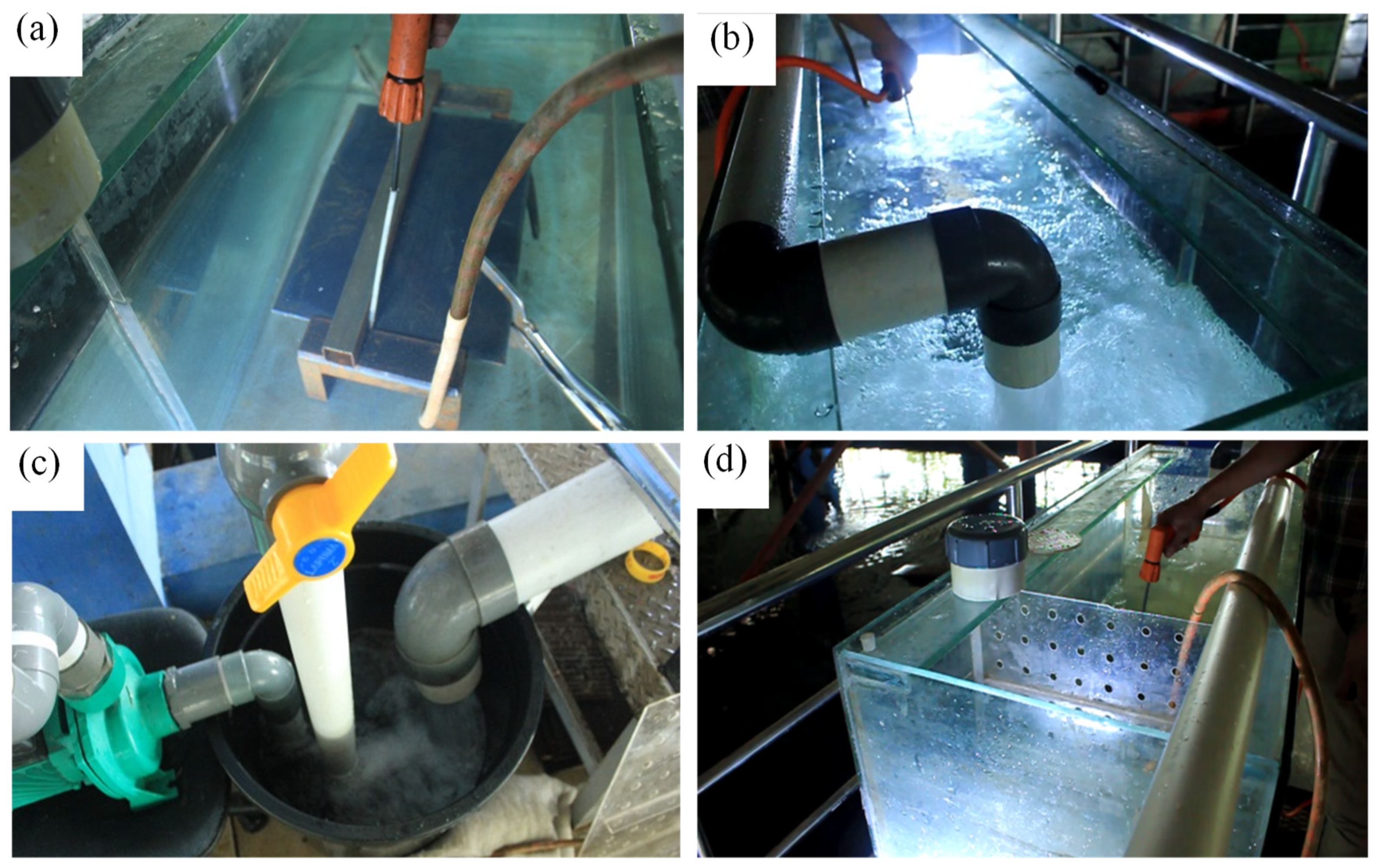
2.1. Material Preparation and Welding Process
2.2. Underwater Bead-On-Plate Testing Properties
3. Results and Discussion
3.1. Physical Properties
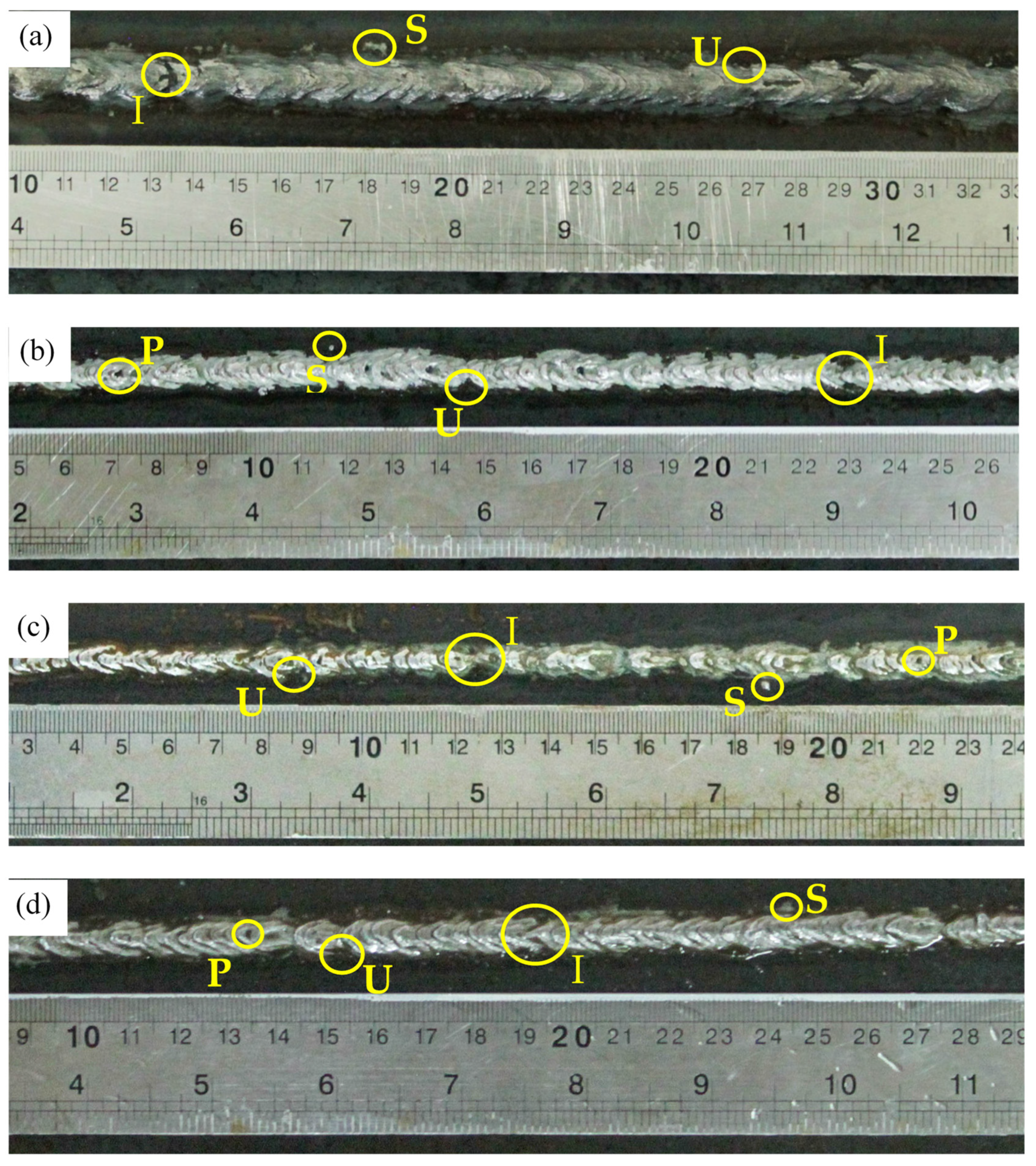
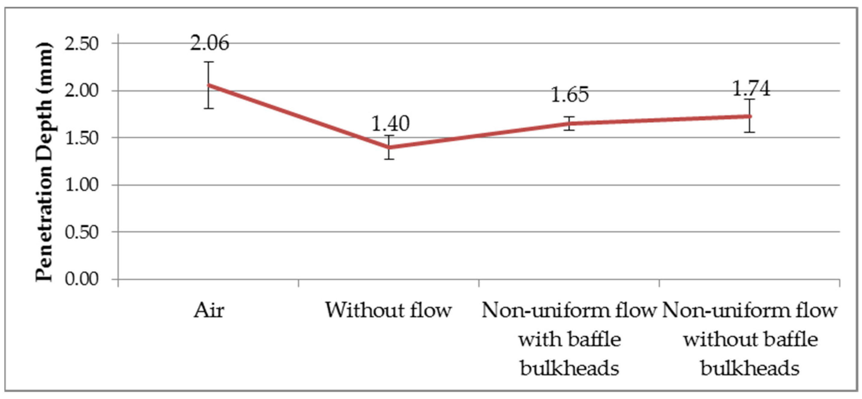
3.1.1. Visual Defect Observation
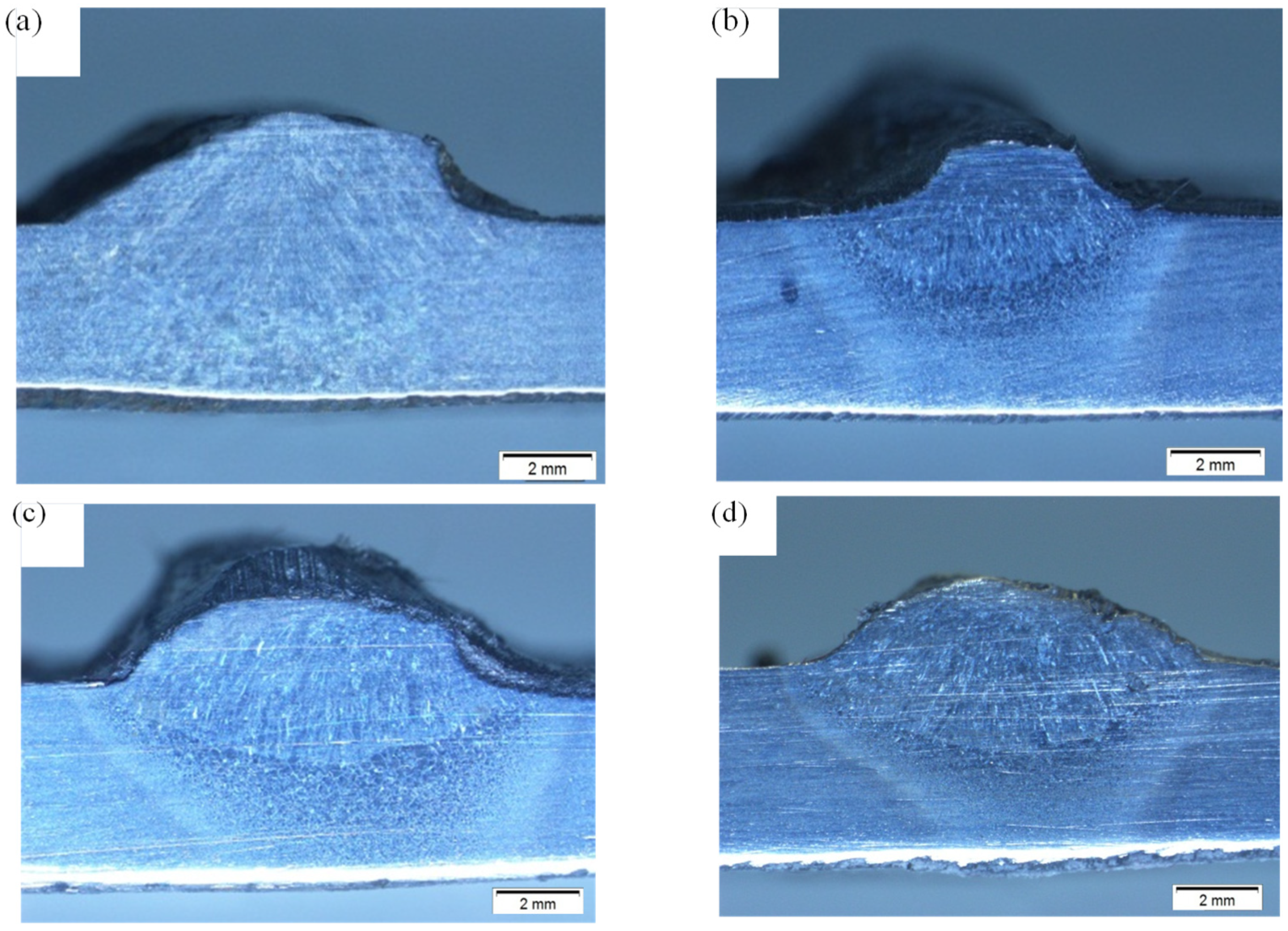
3.1.2. Macrostructure and Microstructure
3.2. Mechanical Properties
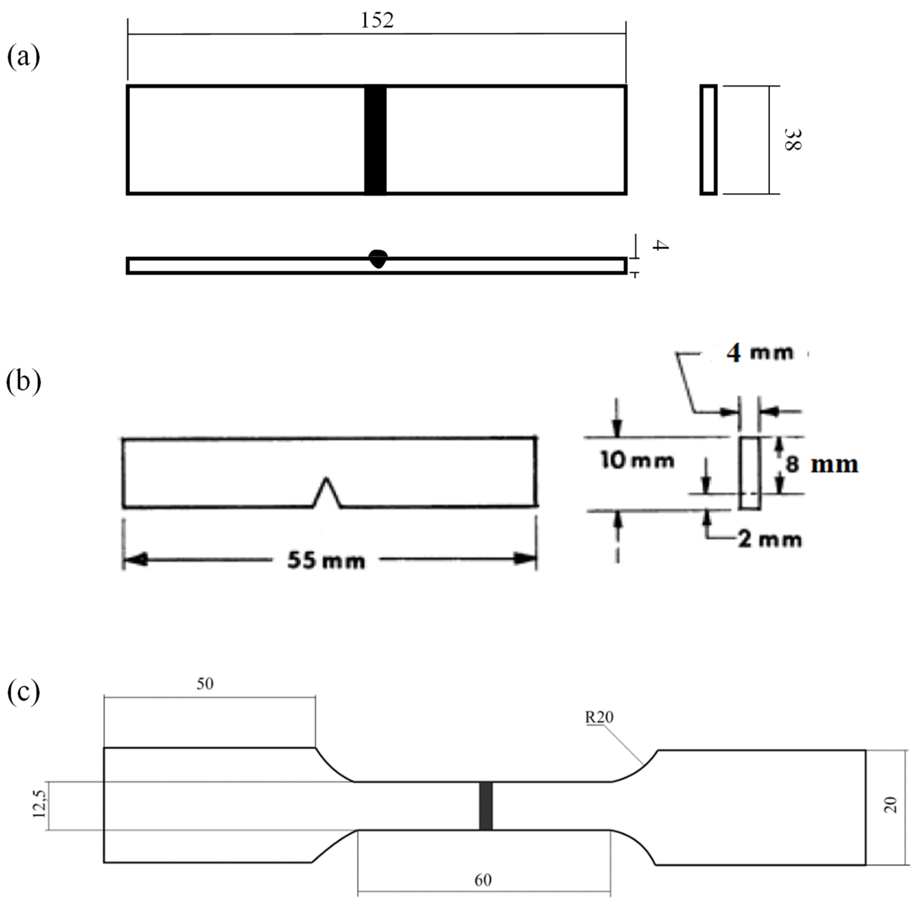
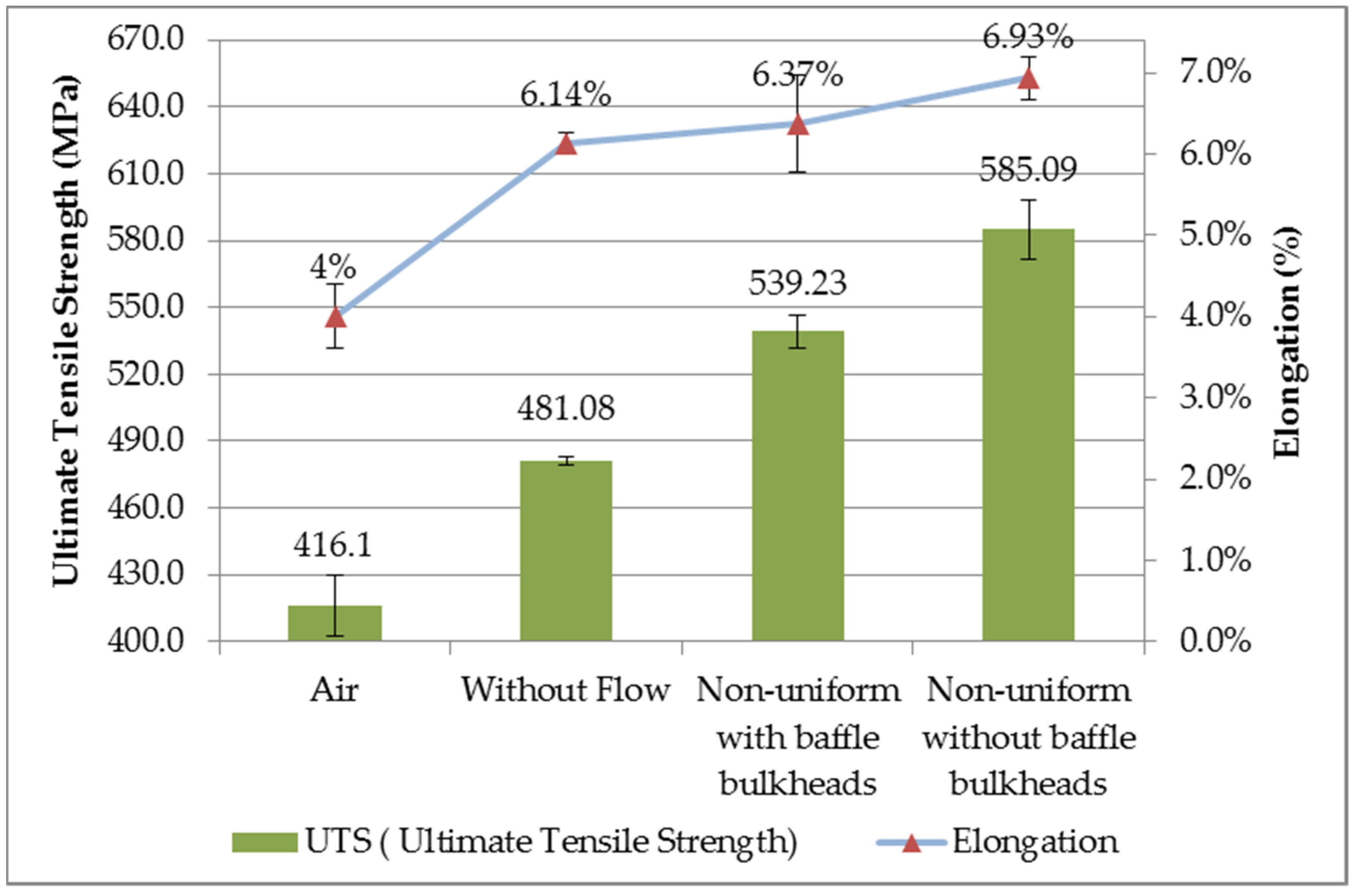
3.2.1. Tensile Strength
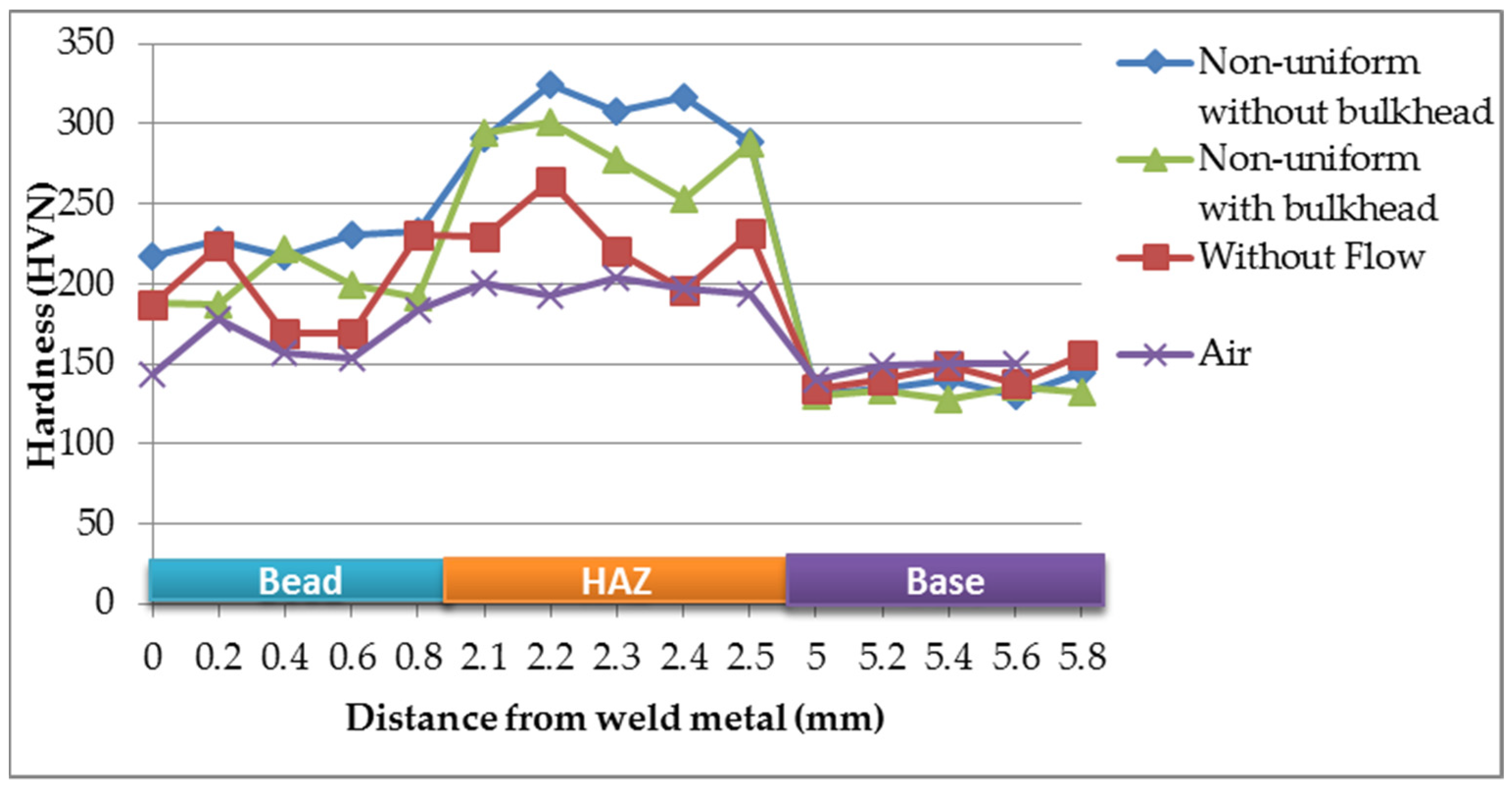
3.2.2. Hardness Test
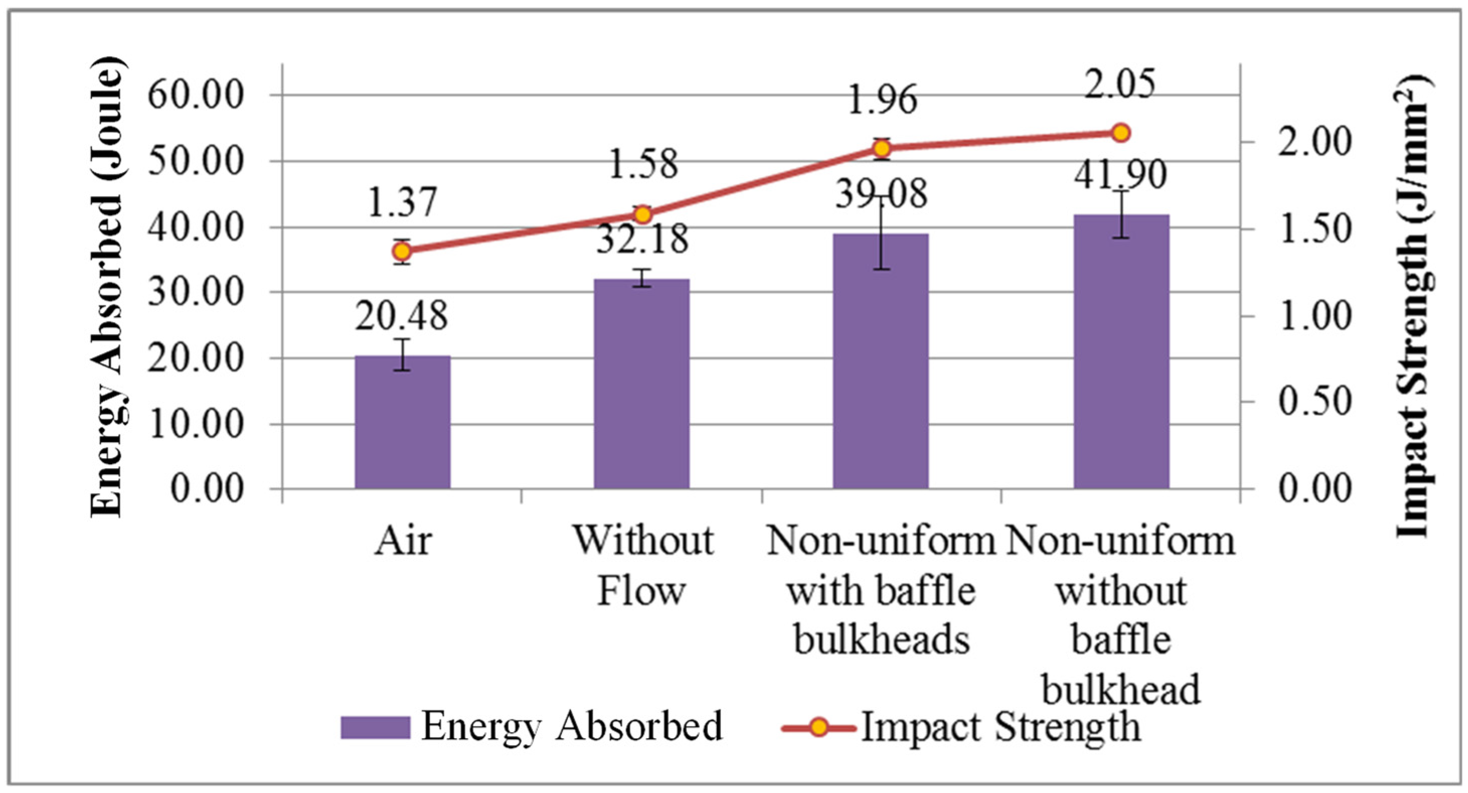
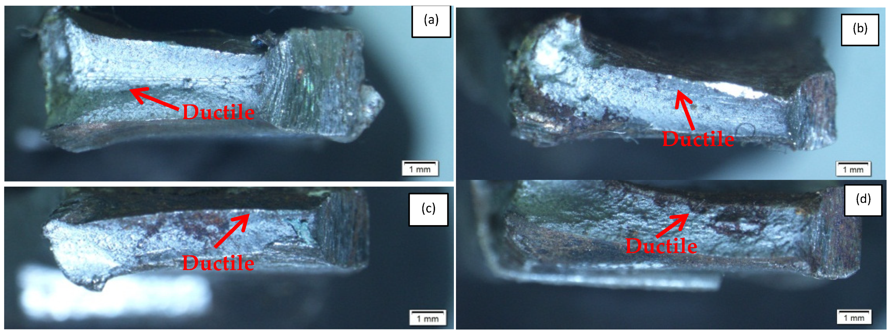
3.2.3. Impact Test
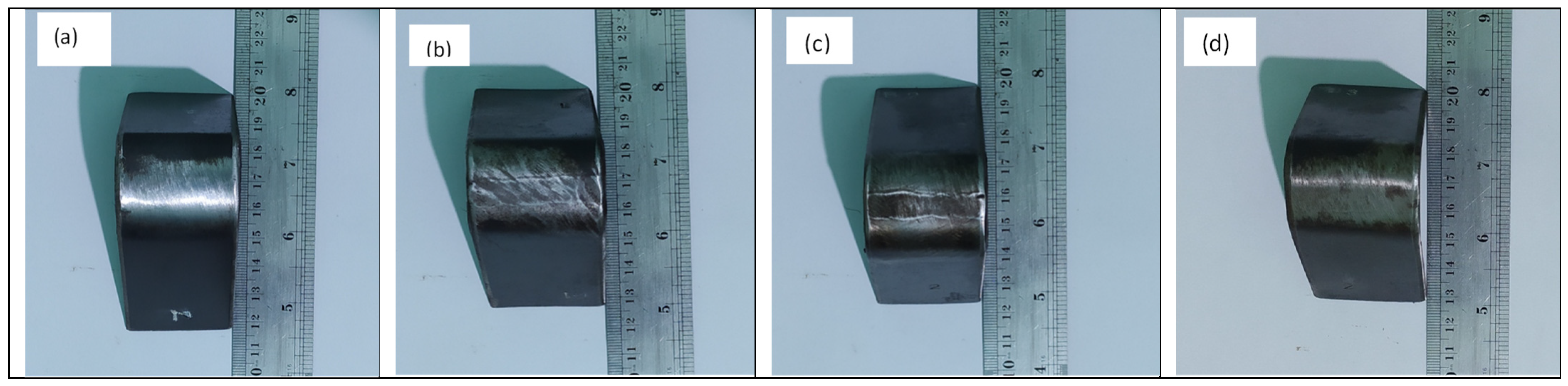
3.2.4. Bending Test
4. Discussion of the Experiments
5. Concluding Remarks
- In terms of the physical properties, more defects, such as porosity and undercut defects, occur in underwater welding than in air welding. The penetration depth is more dependent on the water flow than the cooling rate. A smaller grain size structure forms in the HAZ area due to the higher flow rate and lower ambient temperature there. Thus, the smallest grain size was found in the specimen exposed to the non-uniform flow condition without a baffle bulkhead.
- In terms of the mechanical properties, the tensile and impact strength values increased as the cooling rate increased. The highest hardness values were found in the HAZ area, and the highest average value occurred in the specimen exposed to the non-uniform flow without a baffle bulkhead. The impact strength was greater in the specimens welded under the following conditions: in the air, with a non-uniform flow with a baffle bulkhead, and with a non-uniform flow or without flow due to the HAZ area in the specimens. The bending test found no defects in any of the specimens because the electrode metal made the specimens stronger.
Author Contributions
Funding
Data Availability Statement
Conflicts of Interest
References
- Sun, K.; Zeng, M.; Shi, Y.; Hu, Y.; Shen, X. Microstructure and corrosion behavior of S32101 stainless steel underwater dry and wet welded joints. J. Mater. Process. Technol. 2018, 256, 190–201. [Google Scholar] [CrossRef]
- Guo, N.; Du, Y.; Feng, J.; Guo, W.; Deng, Z. Study of underwater wet welding stability using an X-ray transmission method. J. Mater. Process. Technol. 2015, 225, 133–138. [Google Scholar] [CrossRef]
- Ibarra, S.; Reed, R.; Smith, J.; Pachniuk, I.; Grubbs, C. The Structural Repair of a North Sea Platform Using Underwater Wet Welding Techniques. In Proceedings of the Offshore Technology Conference, Houston, TX, USA, 6–9 May 1991. [Google Scholar] [CrossRef]
- Klett, J.; Mattos, I.B.F.; Maier, H.J.; e Silva, R.H.G.; Hassel, T. Control of the diffusible hydrogen content in different steel phases through the targeted use of different welding consumables in underwater wet welding. Mater. Corros. 2021, 72, 504–516. [Google Scholar] [CrossRef]
- Fydrych, D.; Łabanowski, J.; Tomków, J.; Rogalski, G. Cold Cracking of Underwater Wet Welded S355G10+N High Strength Steel. Adv. Mater. Sci. 2015, 15, 48–56. [Google Scholar] [CrossRef]
- Tomków, J.; Fydrych, D.; Rogalski, G.; Łabanowski, J. Temper Bead Welding of S460N Steel in Wet Welding Conditions. Adv. Mater. Sci. 2018, 18, 5–14. [Google Scholar] [CrossRef]
- Chen, H.; Guo, N.; Shi, X.; Du, Y.; Feng, J.; Wang, G. Effect of water flow on the arc stability and metal transfer in underwater flux-cored wet welding. J. Manuf. Process. 2018, 31, 103–115. [Google Scholar] [CrossRef]
- Zhang, Y.; Jia, C.; Zhao, B.; Hu, J.; Wu, C. Heat input and metal transfer influences on the weld geometry and microstructure during underwater wet FCAW. J. Mater. Process. Technol. 2016, 238, 373–382. [Google Scholar] [CrossRef]
- Pessoa, E.C.P.; Bracarense, A.Q.; Zica, E.M.; Liu, S.; Perez-Guerrero, F. Porosity variation along multipass underwater wet welds and its influence on mechanical properties. J. Mater. Process. Technol. 2006, 179, 239–243. [Google Scholar] [CrossRef]
- Omajene, J.E.; Martikainen, J.; Kah, P. Effect of Welding Parameters on Weld Bead Shape for Welds Done Underwater. Int. J. Mech. Eng. Appl. 2014, 2, 128. [Google Scholar] [CrossRef]
- Çolak, Z.; Ayan, Y.; Kahraman, N. Weld morphology and mechanical performance of marine structural steel welded underwater in a real marine environment. Int. J. Adv. Manuf. Technol. 2020, 109, 1–11. [Google Scholar] [CrossRef]
- Di, X.; Ji, S.; Cheng, F.; Wang, D.; Cao, J. Effect of cooling rate on microstructure, inclusions and mechanical properties of weld metal in simulated local dry underwater welding. Mater. Des. 2015, 88, 505–513. [Google Scholar] [CrossRef]
- Guo, N.; Xu, C.; Guo, W.; Du, Y.; Feng, J. Characterization of spatter in underwater wet welding by X-ray transmission method. Mater. Des. 2015, 85, 156–161. [Google Scholar] [CrossRef]
- Wang, J.; Sun, Q.; Zhang, S.; Wang, C.; Wu, L.; Feng, J. Characterization of the underwater welding arc bubble through a visual sensing method. J. Mater. Process. Technol. 2018, 251, 95–108. [Google Scholar] [CrossRef]
- Gao, W.; Wang, D.; Cheng, F.; Di, X.; Deng, C.; Xu, W. Microstructural and mechanical performance of underwater wet welded S355 steel. J. Mater. Process. Technol. 2016, 238, 333–340. [Google Scholar] [CrossRef]
- American Society for Testing and Materials. ASTM E407-07e1: Standard Practice for Microetching Metals and Alloys; Annu. B ASTM Stand: West Conshohocken, PA, USA, 2007; p. 22. [Google Scholar] [CrossRef]
- ASTM-E92. Standard Test Method for Vickers Hardness of Metallic Materials. ASTM Int. 1997, 82, 1–10. [Google Scholar]
- Sulamet-Ariobimo, R.D.; Soedarsono, J.W.; Sukarnoto, T.; Rustandi, A.; Mujalis, Y.; Prayitno, D. Tensile properties analysis of AA1100 aluminium and SS400 steel using different JIS tensile standard specimen. J. Appl. Res. Technol. 2016, 14, 148–153. [Google Scholar] [CrossRef]
- ASTM E 23-12c, Standard Test Methods for Notched Bar Impact Testing of Metallic Materials; ASTM International: West Conshohocken, PA, USA, 2013; pp. 1–25. [CrossRef]
- Chen, H.; Guo, N.; Huang, L.; Zhang, X.; Feng, J.; Wang, G. Effects of arc bubble behaviors and characteristics on droplet transfer in underwater wet welding using in-situ imaging method. Mater. Des. 2019, 170, 107696. [Google Scholar] [CrossRef]
- Wei, P.S. Thermal Science of Weld Bead Defects: A Review. J. Heat Transf. 2010, 133, 031005. [Google Scholar] [CrossRef]
- Chen, H.; Guo, N.; Shi, X.; Du, Y.; Feng, J.; Wang, G. Effect of hydrostatic pressure on protective bubble characteristic and weld quality in underwater flux-cored wire wet welding. J. Mater. Process. Technol. 2018, 259, 159–168. [Google Scholar] [CrossRef]
- Kumar, R.; Chattopadhyaya, S.; Kumar, S. Influence of Welding Current on Bead Shape, Mechanical and Structural Property of Tungsten Inert Gas Welded Stainless Steel Plate. Mater. Today Proc. 2015, 2, 3342–3349. [Google Scholar] [CrossRef]
- Nixondg, J.; Billingham, J. A survey of underwater welding techniques. Endeavour 1987, 11, 143–148. [Google Scholar] [CrossRef]
- Surojo, E.; Wicaksana, N.I.; Saputro, Y.C.N.; Budiana, E.P.; Muhayat, N.; Triyono; Prabowo, A.R. Effect of Welding Parameter on the Corrosion Rate of Underwater Wet Welded SS400 Low Carbon Steel. Appl. Sci. 2020, 10, 5843. [Google Scholar] [CrossRef]
- Surojo, E.; Anindito, J.; Paundra, F.; Prabowo, A.R.; Budiana, E.P.; Muhayat, N.; Badaruddin, M.; Triyono. Effect of water flow and depth on fatigue crack growth rate of underwater wet welded low carbon steel SS400. Open Eng. 2021, 11, 329–338. [Google Scholar] [CrossRef]
- Thakur, P.P.; Chapgaon, A.N. A Review on Effects of GTAW Process Parameters on weld. Int. J. Res. Appl. Sci. Eng. Technol. 2016, 4, 136–140. [Google Scholar] [CrossRef]
- Mirzaei, M.; Jeshvaghani, R.A.; Yazdipour, A.; Zangeneh-Madar, K. Study of welding velocity and pulse frequency on microstructure and mechanical properties of pulsed gas metal arc welded high strength low alloy steel. Mater. Des. 2013, 51, 709–713. [Google Scholar] [CrossRef]
- Surojo, E.; Gumilang, A.; Triyono, T.; Prabowo, A.; Budiana, E.; Muhayat, N. Effect of Water Flow on Underwater Wet Welded A36 Steel. Metals 2021, 11, 682. [Google Scholar] [CrossRef]
- Jeongung, P.; An, G. Dissimilar Welding of Low Alloy Steels Welded Joints: Effect of Run-Off and Run-On Plates. Metals 2021, 11, 642. [Google Scholar] [CrossRef]
- Duan, W.; Niu, X.; Gan, T.-H.; Kanfoud, J.; Chen, H.-P. A Numerical Study on the Excitation of Guided Waves in Rectangular Plates Using Multiple Point Sources. Metals 2017, 7, 552. [Google Scholar] [CrossRef]
- Prabowo, A.R.; Cao, B.; Sohn, J.M.; Bae, D.M. Crashworthiness assessment of thin-walled double bottom tanker: Influences of seabed to structural damage and damage-energy formulae for grounding damage calculations. J. Ocean Eng. Sci. 2020, 5, 387–400. [Google Scholar] [CrossRef]
- Prabowo, A.R.; Bae, D.M. Environmental risk of maritime territory subjected to accidental phenomena: Correlation of oil spill and ship grounding in the Exxon Valdez’s case. Results Eng. 2019, 4, 100035. [Google Scholar] [CrossRef]
- Prabowo, A.R.; Laksono, F.B.; Sohn, J.M. Investigation of structural performance subjected to impact loading using finite element approach: Case of ship-container collision. Curved Layer. Struct. 2020, 7, 17–28. [Google Scholar] [CrossRef]
- Prabowo, A.R.; Bahatmaka, A.; Sohn, J.M. Crashworthiness characteristic of longitudinal deck structures against identified accidental action in marine environment: A study case of ship–bow collision. J. Braz. Soc. Mech. Sci. Eng. 2020, 42, 1–13. [Google Scholar] [CrossRef]
- Grammatikopoulos, A. The effects of geometric detail on the vibratory responses of complex ship-like thin-walled structures. Mar. Struct. 2021, 78, 103013. [Google Scholar] [CrossRef]
- Yusvika, M.; Prabowo, A.R.; Tjahjana, D.D.D.P.; Sohn, J.M. Cavitation Prediction of Ship Propeller Based on Temperature and Fluid Properties of Water. J. Mar. Sci. Eng. 2020, 8, 465. [Google Scholar] [CrossRef]
- Prabowo, A.R.; Byeon, J.H.; Cho, H.J.; Sohn, J.M.; Bae, D.M.; Cho, J.H.; Indriastuti, A.K.; Yulipriyono, E. Impact phenomena assessment: Part I—Structural performance of a tanker subjected to ship grounding at the Arctic. MATEC Web Conf. 2018, 159, 02061. [Google Scholar] [CrossRef]
- Bae, D.M.; Prabowo, A.R.; Cao, B.; Sohn, J.M.; Zakki, A.; Wang, Q. Numerical Simulation for the Collision Between Side Structure and Level Ice in Event of Side Impact Scenario. Lat. Am. J. Solids Struct. 2016, 13, 2991–3004. [Google Scholar] [CrossRef][Green Version]
- Rajagopal, S.; Zhang, P. How widespread is the usage of the Northern Sea Route as a commercially viable shipping route? A statistical analysis of ship transits from 2011 to 2018 based on empirical data. Mar. Policy 2021, 125, 104300. [Google Scholar] [CrossRef]
- Sibul, G.; Jin, J.G. Evaluating the feasibility of combined use of the Northern Sea Route and the Suez Canal Route considering ice parameters. Transp. Res. Part A Policy Pract. 2021, 147, 350–369. [Google Scholar] [CrossRef]
- Prabowo, A.; Tuswan, T.; Ridwan, R. Advanced Development of Sensors’ Roles in Maritime-Based Industry and Research: From Field Monitoring to High-Risk Phenomenon Measurement. Appl. Sci. 2021, 11, 3954. [Google Scholar] [CrossRef]


| Chemical Composition (wt %) | C | Mn | P | S | Si | Ni | Cr | Mo | Cu | Fe |
|---|---|---|---|---|---|---|---|---|---|---|
| ASTM A36 | 0.19 | 0.472 | 0.018 | <0.01 | 0.129 | 0.014 | 0.025 | 0.036 | 0.01 | Bal. |
| No | Variation | Parameter Temperature (°C) | Type of Flow | Defects | Amount |
|---|---|---|---|---|---|
| 1 | A0 | 35 | Air | Undercut (U) | 6 |
| Spatter (S) | 84 | ||||
| Irregular Surface (I) | 1 | ||||
| 2 | A1 | 10 ± 5 | Without Flow | Porosity(P) | 12 |
| Undercut (U) | 8 | ||||
| Spatter (S) | 10 | ||||
| Irregular Surface (I) | 3 | ||||
| 3 | A2 | 10 ± 5 | Non-uniform with baffle bulkhead | Porosity (P) | 15 |
| Undercut (U) | 5 | ||||
| Spatter (S) | 2 | ||||
| Irregular Surface (I) | 4 | ||||
| 4 | A3 | 10 ± 5 | Non-uniform without baffle bulkhead | Porosity (P) | 18 |
| Undercut (U) | 4 | ||||
| Spatter (S) | 3 | ||||
| Irregular Surface (I) | 4 |
| Variation | Base Metal | Heat-Affected Zone | Weld Metal |
|---|---|---|---|
| Air Condition |  |  |  |
| Without Flow Condition |  |  |  |
| Non-uniform flow without bulkhead |  |  |  |
| Non-uniform with bulkhead |  |  |  |
Publisher’s Note: MDPI stays neutral with regard to jurisdictional claims in published maps and institutional affiliations. |
© 2021 by the authors. Licensee MDPI, Basel, Switzerland. This article is an open access article distributed under the terms and conditions of the Creative Commons Attribution (CC BY) license (https://creativecommons.org/licenses/by/4.0/).
Share and Cite
Surojo, E.; Aji, R.P.; Triyono, T.; Budiana, E.P.; Prabowo, A.R. Mechanical and Microstructural Properties of A36 Marine Steel Subjected to Underwater Wet Welding. Metals 2021, 11, 999. https://doi.org/10.3390/met11070999
Surojo E, Aji RP, Triyono T, Budiana EP, Prabowo AR. Mechanical and Microstructural Properties of A36 Marine Steel Subjected to Underwater Wet Welding. Metals. 2021; 11(7):999. https://doi.org/10.3390/met11070999
Chicago/Turabian StyleSurojo, Eko, Raka Pungkas Aji, Triyono Triyono, Eko Prasetya Budiana, and Aditya Rio Prabowo. 2021. "Mechanical and Microstructural Properties of A36 Marine Steel Subjected to Underwater Wet Welding" Metals 11, no. 7: 999. https://doi.org/10.3390/met11070999
APA StyleSurojo, E., Aji, R. P., Triyono, T., Budiana, E. P., & Prabowo, A. R. (2021). Mechanical and Microstructural Properties of A36 Marine Steel Subjected to Underwater Wet Welding. Metals, 11(7), 999. https://doi.org/10.3390/met11070999