
Microstructural and Cavitation Erosion Behavior of the CuAlNi Shape Memory Alloy

 ,
,  , ,
, , 
Abstract
:1. Introduction
- Casting route (conventional casting route with and without quaternary addition);
- Powder metallurgy route (mechanical alloying followed by sintering process, mechanical alloying followed by hot pressing and extrusion process, mechanical alloying of pre-alloyed powders followed by hot isostatic pressing, mechanical alloying of elemental and pre-alloyed powders followed by sintering and hot rolling);
- Rapid solidification processing route;
- Spray casting route.
2. Experimental
2.1. Synthesis
2.2. Cavitation Test
2.3. Methods for Monitoring the Cavitation Testing
2.3.1. Mass Loss
2.3.2. Optical Microscopy
2.3.3. SEM
2.3.4. AFM
2.3.5. Microhardness
3. Results and Discussion
4. Conclusions
Author Contributions
Funding
Conflicts of Interest
References
- Otsuka, K.; Wayman, C.M. Shape Memory Materials; Cambridge University Press: Cambridge, UK, 1998. [Google Scholar]
- Lexcellent, C. Shape-Memory Alloys Handbook; John Wiley & Sons: New York, NY, USA, 2013. [Google Scholar]
- Jani, J.M.; Leary, M.; Subic, A.; Gibson, M.A. A review of shape memory alloy research, applications and opportunities. Mater. Des. 2014, 56, 1078–1113. [Google Scholar] [CrossRef]
- Dasgupta, R. A look into Cu-based shape memory alloys: Present scenario and future prospects. J. Mater. Res. 2014, 29, 1681–1698. [Google Scholar] [CrossRef]
- Arlic, U.; Zak, H.; Weidenfeller, B.; Riehemann, W. Impact of Alloy Composition and Thermal Stabilization on Martensitic Phase Transformation Structures in CuAlMn Shape Memory Alloys. Mater. Res. 2018, 21, 20170897. [Google Scholar] [CrossRef] [Green Version]
- Agrawal, A.; Dube, R.K. Methods of fabricating Cu-Al-Ni shape memory alloys. J. Alloys Compd. 2018, 750, 235–247. [Google Scholar] [CrossRef]
- Gojić, M.; Vrsalović, L.; Kožuh, S.; Kneissl, A.; Anzel, I.; Gudić, S.; Kosec, B.; Kliškić, M. Electrochemical and microstructural study of Cu–Al–Ni shape memory alloy. J. Alloys Compd. 2011, 509, 9782–9790. [Google Scholar] [CrossRef]
- Lojen, G.; Gojić, M.; Anžel, I. Continuously cast Cu–Al–Ni shape memory alloy—Properties in as-cast condition. J. Alloys Compd. 2013, 580, 497–505. [Google Scholar] [CrossRef]
- Pereira, E.C.; Matlakhova, L.; Matlakhov, A.N.; De Araújo, C.J.; Shigue, C.; Monteiro, S.N. Reversible martensite transformations in thermal cycled polycrystalline Cu-13.7%Al-4.0%Ni alloy. J. Alloys Compd. 2016, 688, 436–446. [Google Scholar] [CrossRef]
- Wang, Z.; Liu, X.-F.; Xie, J.-X. Effects of solidification parameters on microstructure and mechanical properties of continuous columnar-grained Cu–Al–Ni alloy. Prog. Nat. Sci. 2011, 21, 368–374. [Google Scholar] [CrossRef] [Green Version]
- Hammit, F.G. Cavitation and Multiphase Flow Phenomena; McGraw-Hill: New York, NY, USA, 1980. [Google Scholar]
- Franc, J.-P.; Michel, J.-M. Fundamentals of Cavitation; Springer Science and Business Media LLC: Berlin, Germany, 2005. [Google Scholar]
- Okada, T.; Iwai, Y.; Hattory, S.; Tanimura, N. Relation between impact load and the damage produced by cavitation babble collapse. Wear 1995, 184, 231–239. [Google Scholar] [CrossRef]
- Hattori, S.; Mori, H.; Okada, T. Quantitative Evaluation of Cavitation Erosion. J. Fluids Eng. 1998, 120, 179–185. [Google Scholar] [CrossRef]
- Czyzniewski, K.A. Cavitation erosion resistance of Cr–N coating deposited on stainless steel. Wear 2006, 260, 1324–1332. [Google Scholar]
- Zhao, J.; Jiang, Z.; Zhu, J.; Zhang, J.; Li, Y. Investigation on Ultrasonic Cavitation Erosion Behaviors of Al and Al-5Ti Alloys in the Distilled Water. Metals 2020, 10, 1631. [Google Scholar] [CrossRef]
- Szala, M.; Łatka, L.; Walczak, M.; Winnicki, M. Comparative study on the cavitation erosion and sliding wear of cold-sprayed Al/Al2O3 and Cu/Al2O3 coatings, and stainless steel, aluminium alloy, copper and brass. Metals 2020, 10, 856. [Google Scholar] [CrossRef]
- Kazasidis, M.; Yin, S.; Cassidy, J.; Volkov-Husović, T.; Vlahović, M.; Martinović, S.; Kyriakopoulou, E.; Lupoi, R. Microstructure and cavitation erosion performance of nickel-Inconel 718 composite coatings produced with cold spray. Surf. Coatings Technol. 2020, 382, 125195. [Google Scholar] [CrossRef]
- Singh, N.K.; Ang, A.S.; Mahajan, D.K.; Singh, H. Cavitation erosion resistant nickel-based cermet coatings for monel K-500. Tribol. Int. 2021, 159, 106954. [Google Scholar] [CrossRef]
- Zakrzewska, D.E.; Krella, A.K. Cavitation Erosion Resistance Influence of Material Properties. Adv. Mater. Sci. 2019, 19, 18–34. [Google Scholar] [CrossRef] [Green Version]
- Szala, M.; Chocyk, D.; Skic, A.; Kaminski, M. Effect of nitrogen ion implatation on the cavitation erosion resistance and cobalt-based solid solution phase transformations of HIPed Stellite 6. Metals 2021, 14, 2324. [Google Scholar]
- Ding, X.; Ke, D.; Yuan, C.; Ding, Z.; Cheng, X. Microstructure and Cavitation Erosion Resistance of HVOF Deposited WC-Co Coatings with Different Sized WC. Coatings 2018, 8, 307. [Google Scholar] [CrossRef] [Green Version]
- Cheng, F.; Shi, P.; Man, H. Cavitation erosion resistance of heat-treated NiTi. Mater. Sci. Eng. A 2003, 339, 312–317. [Google Scholar] [CrossRef]
- Hattori, S.; Tainaka, A. Cavitation erosion of Ti–Ni base shape memory alloys. Wear 2007, 262, 191–197. [Google Scholar] [CrossRef]
- Yang, L.; Tieu, A.; Dunne, D.; Huang, S.; Li, H.; Wexler, D.; Jiang, Z. Cavitation erosion resistance of NiTi thin films produced by Filtered Arc Deposition. Wear 2009, 267, 233–243. [Google Scholar] [CrossRef] [Green Version]
- Wang, Z.; Zhu, J. Cavitation erosion of Fe-Mn-Si-Cr shape memory alloys. Wear 2004, 256, 66–72. [Google Scholar] [CrossRef]
- Matovic, B.; Maksimovic, V.; Bucevac, D.; Pantic, J.; Lukovic, J.; Volkov-Husovic, T.; Gautam, D. Oxidation and erosion behaviour of SiC-HfC multilayered composite. Process. Appl. Ceram. 2014, 8, 31–38. [Google Scholar] [CrossRef]
- Cheng, F.; Jiang, S. Cavitation erosion resistance of diamond-like carbon coating on stainless steel. Appl. Surf. Sci. 2014, 292, 16–26. [Google Scholar] [CrossRef]
- Fatjo, G.G.-A.; Hadfield, M.; Tabeshfar, K. Pseudoplastic deformation pits on polished ceramics due to cavitation erosion. Ceram. Int. 2011, 37, 1919–1927. [Google Scholar] [CrossRef]
- Martinović, S.; Vlahović, M.; Boljanac, T.; Dojčinović, M.; Volkov-Husović, T. Cavitation resistance of refractory concrete: Influence of sintering temperature. J. Eur. Ceram. Soc. 2013, 33, 7–14. [Google Scholar] [CrossRef]
- Algellai, A.A.; Tomić, N.; Vuksanović, M.M.; Dojčinović, M.; Volkov-Husović, T.; Radojević, V.; Heinemann, R.J. Adhesion testing of composites based on Bis-GMA/TEGDMA monomers reinforced with alumina based fillers on brass substrate. Compos. Part B Eng. 2018, 140, 164–173. [Google Scholar] [CrossRef]
- Ashor, A.A.; Vuksanović, M.M.; Tomic, N.; Petrović, M.; Dojčinović, M.; Husović, T.V.; Radojević, V.; Heinemann, R.J. Optimization of modifier deposition on the alumina surface to enhance mechanical properties and cavitation resistance. Polym. Bull. 2019, 77, 3603–3620. [Google Scholar] [CrossRef]
- Obradovic, V.; Vuksanovic, M.; Tomic, N.; Stojanovic, D.; Volkov-Husovic, T.; Uskokovic, P. Improvement in cavitation resistance of poly (vinyl butyral) composite films with silica nanoparticles: A technical note. Polym. Compos. 2021. [Google Scholar] [CrossRef]
- ASTM. ASTM Standard G32-98 Standard, Test Method for Cavitation Erosion Using Vibratory Apparatus. In Annual Book of ASTM Standards; ASTM: West Conshohocken, PA, USA, 2000. [Google Scholar]
- Recarte, V.; Pérez-Landazábal, J.; Rodríguez, P.; Bocanegra, E.; Nó, M.; Juan, J.S. Thermodynamics of thermally induced martensitic transformations in Cu–Al–Ni shape memory alloys. Acta Mater. 2004, 52, 3941–3948. [Google Scholar] [CrossRef]
- Ivanić, I.; Kožuh, S.; Kurajica, S.; Kosec, B.; Anžel, I.; Gojić, M. XRD analysis of CuAlNi shape memory alloy before and after heat treatment. In Proceedings of the Mechanical Technologies and Structural Materials, Split, Croatia, 22–23 September 2016; Croatian Science Foundation: Opatija, Croatia, 2016; pp. 55–60. [Google Scholar]
- Peña, J.; Gil, F.; Guilemany, J. Effect of microstructure on dry sliding wear behaviour in CuZnAl shape memory alloys. Acta Mater. 2002, 50, 3117–3126. [Google Scholar] [CrossRef]
- Pošarac-Marković, M.; Veljovic, D.; Devečerski, A.; Matović, B.; Volkov-Husovic, T. Nondestructive evaluation of surface degradation of silicon carbide–cordierite ceramics subjected to the erosive wear. Mater. Des. 2013, 52, 295–299. [Google Scholar] [CrossRef]
- Dojčinović, M.; Volkov-Husović, T. Cavitation damage of the medium carbon steel: Implementation of image analysis. Mater. Lett. 2008, 62, 953–956. [Google Scholar] [CrossRef]
- Jiang, S.; Ding, H.; Xu, J. Cavitation Erosion Resistance of Sputter-Deposited Cr3Si Film on Stainless Steel. J. Tribol. 2016, 139, 014501. [Google Scholar] [CrossRef]


| Parameter | As-Cast State (L) | Heat-Treated (Quenched) State (K2) |
|---|---|---|
| Average Values | ||
| Area, µm | 1.235312 | 36.13774 |
| Diameter (max), µm | 1.334329 | 9.553893 |
| Diameter (min), µm | 0.773391 | 3.257734 |
| Diameter (mean), µm | 1.051157 | 6.288539 |
| Radius (min), µm | 0.337882 | 0.724588 |
| Perimeter, µm | 1.858238 | 34.40823 |
| Perimeter 2, µm | 2.086906 | 47.0361 |
| Fractal dimension | 0.009532 | 1.25286 |
| Perimeter 3, µm | 2.147028 | 38.70619 |
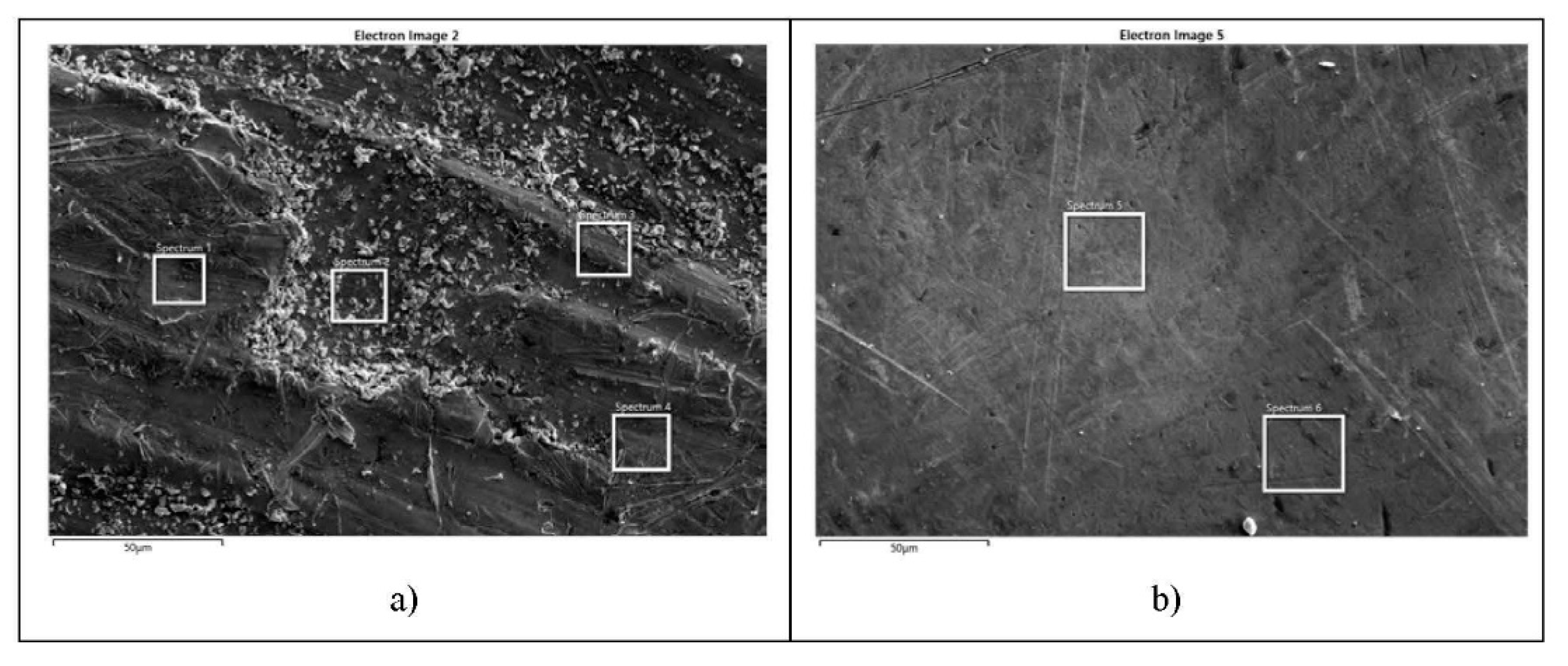
| Result Type | Weight % | |||||
|---|---|---|---|---|---|---|
| Spectrum Label | Spectrum 1 | Spectrum 2 | Spectrum 3 | Spectrum 4 | ||
| L | 12.55 | 12.41 | 12.93 | 12.9 | ||
| Ni | 4.73 | 5.65 | 4.8 | 4.62 | ||
| Cu | 82.72 | 81.94 | 82.26 | 82.48 | ||
| Total | 100 | 100 | 100 | 100 | ||
| Statistics | Al | Ni | Cu | |||
| Max | 12.93 | 5.65 | 82.72 | |||
| Min | 12.41 | 4.62 | 81.94 | |||
| Average | 12.7 | 4.95 | 82.35 | |||
| Standard deviation | 0.26 | 0.47 | 0.33 | |||
| Result Type | Weight % | Weight % | |
|---|---|---|---|
| Spectrum Label | Spectrum 5 | Spectrum 6 | |
| Al | 12.38 | 12.88 | |
| Ni | 5.38 | 4.38 | |
| Cu | 82.24 | 82.74 | |
| Total | 100 | 100 | |
| Statistics | Al | Ni | Cu |
| Max | 12.88 | 5.38 | 82.74 |
| Min | 12.38 | 4.38 | 82.24 |
| Average | 12.63 | 4.88 | 82.49 |
| Standard deviation | 0.35 | 0.71 | 0.35 |
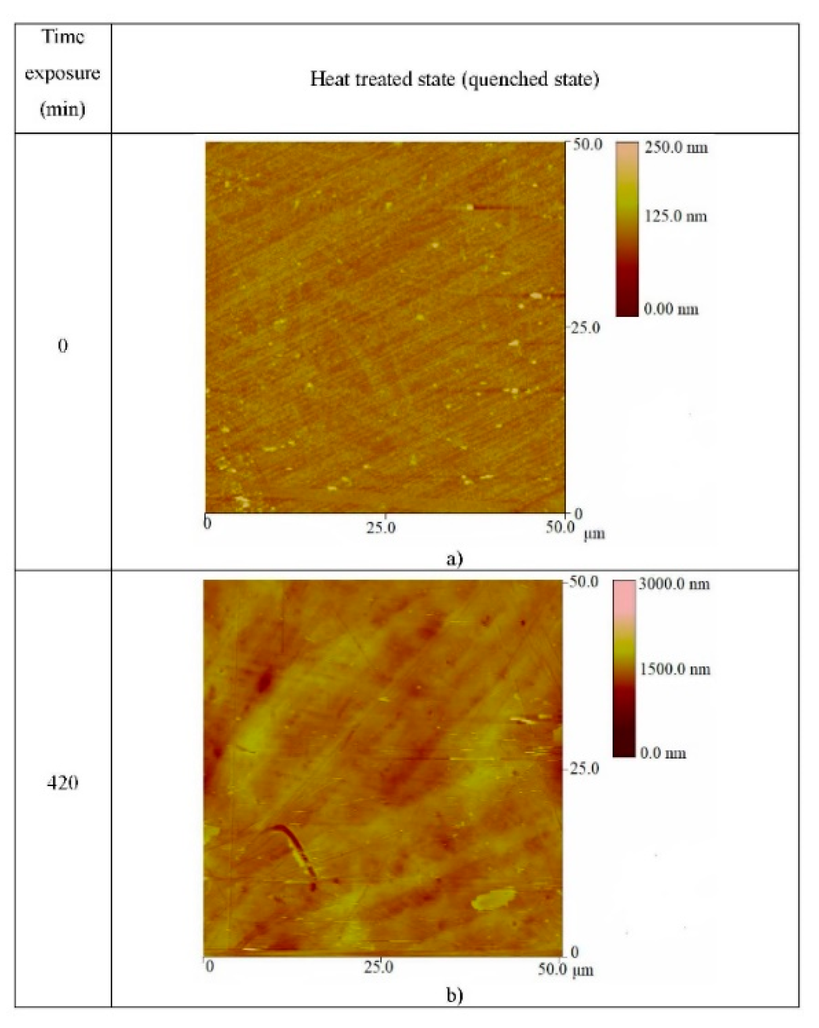
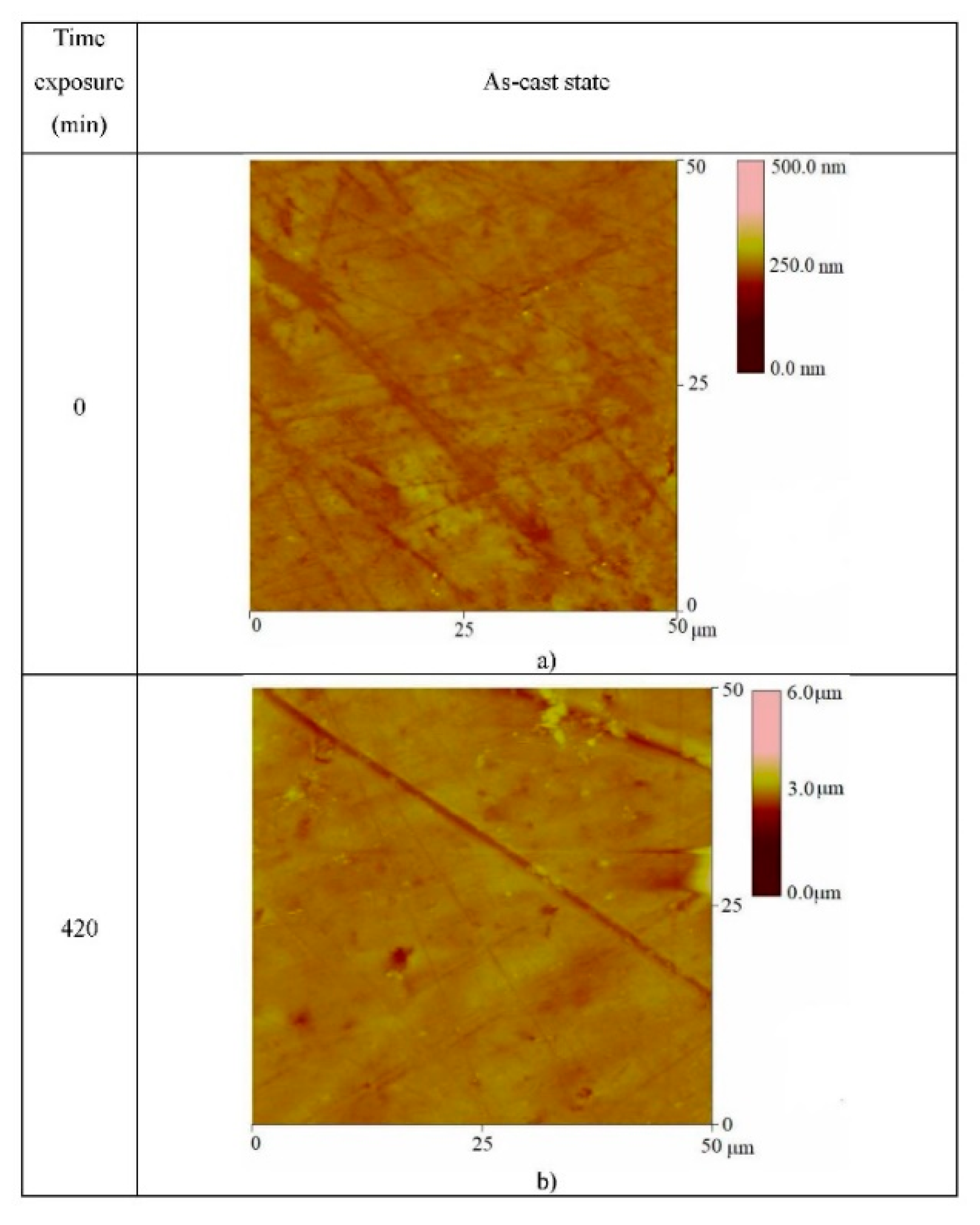
| State of Specimens | Surface Roughness (nm) at Time of Exposure of 0 min | Surface Roughness (nm) at Time of Exposure of 420 min |
|---|---|---|
| As-cast state | 9.33 | 84.185 |
| Heat-treated (quenched) state | 13.11 | 66.846 |
Publisher’s Note: MDPI stays neutral with regard to jurisdictional claims in published maps and institutional affiliations. |
© 2021 by the authors. Licensee MDPI, Basel, Switzerland. This article is an open access article distributed under the terms and conditions of the Creative Commons Attribution (CC BY) license (https://creativecommons.org/licenses/by/4.0/).
Share and Cite
Volkov-Husović, T.; Ivanić, I.; Kožuh, S.; Stevanović, S.; Vlahović, M.; Martinović, S.; Stopic, S.; Gojić, M. Microstructural and Cavitation Erosion Behavior of the CuAlNi Shape Memory Alloy. Metals 2021, 11, 997. https://doi.org/10.3390/met11070997
Volkov-Husović T, Ivanić I, Kožuh S, Stevanović S, Vlahović M, Martinović S, Stopic S, Gojić M. Microstructural and Cavitation Erosion Behavior of the CuAlNi Shape Memory Alloy. Metals. 2021; 11(7):997. https://doi.org/10.3390/met11070997
Chicago/Turabian StyleVolkov-Husović, Tatjana, Ivana Ivanić, Stjepan Kožuh, Sanja Stevanović, Milica Vlahović, Sanja Martinović, Srecko Stopic, and Mirko Gojić. 2021. "Microstructural and Cavitation Erosion Behavior of the CuAlNi Shape Memory Alloy" Metals 11, no. 7: 997. https://doi.org/10.3390/met11070997
APA StyleVolkov-Husović, T., Ivanić, I., Kožuh, S., Stevanović, S., Vlahović, M., Martinović, S., Stopic, S., & Gojić, M. (2021). Microstructural and Cavitation Erosion Behavior of the CuAlNi Shape Memory Alloy. Metals, 11(7), 997. https://doi.org/10.3390/met11070997