Article

Formation and Evolution of DS-Type Inclusions in 15-5PH Stainless Steel

1
State Key Laboratory of Advanced Metallurgy, University of Science and Technology Beijing, Beijing 100083, China
2
CITIC Heavy Machinery Co., Ltd., Luoyang 471039, China
*
Author to whom correspondence should be addressed.
Metals 2021, 11(7), 1129; https://doi.org/10.3390/met11071129
Submission received: 18 May 2021 / Revised: 21 June 2021 / Accepted: 13 July 2021 / Published: 16 July 2021

Abstract

:
15-5PH stainless steel castings are key components in fracturing trucks. However, DS-type inclusions can lead to fatigue failure of the material. To elucidate the formation mechanism of large-size DS-type inclusions, the evolution, growth, and aggregation of inclusions during vacuum oxygen decarburization, ladle refining, and vacuum casting were studied. The results show that the DS-type inclusions with sizes larger than 20 μm were CaO–Al2O3–SiO2–MgO–CaS composite inclusions. After Si–Al additions in vacuum degassing, typical inclusions were spinel or Al2O3. After Ca–Si additions during ladle treatment, typical inclusions were liquid or dual-phase Al2O3–CaO–SiO2–MgO. During the solidification process, due to the segregation of S and the decrease in solubility, the typical inclusions in the final casting became Al2O3–CaO–SiO2–MgO–CaS. For optimal fatigue performance of stainless steel castings, slag and refractory composition control were also necessary because the [Mg] contents mainly come from the slag and lining.

1. Introduction

15-5PH stainless steel is an important material for the production of key components of fracturing trucks. As the core material of fracturing truck needs to work in high pressure environments and in high concentrations hydrochloric acid fluid medium for a long time, it was required to have strong acid resistance and high cycle fatigue [1,2]. The fatigue life of 15-5PH stainless steel forgings has become an important factor that restricts its wide application [3,4]. Many studies have shown that DS-type inclusions were one of the main causes of fatigue failure in steel [5,6,7,8,9,10,11,12]. The DS-type inclusions were one classification of the inclusion, also known as point-like non-deformable inclusions. In ISO 4967:1998, the concept of DS-type inclusions was proposed as circular or nearly circular single-particle inclusions with diameters greater than or equal to 13 μm [13].
Currently, research on DS-type inclusions has mainly focused on bearing steel. Wu et al. [14] found two typical DS-type inclusions in the refining process for bearing steel. Type I was CaO–MgO–Al2O3–SiO2 uniformly distributed and wrapped by CaS. Type II was a composite inclusion with MgO–Al2O3 as the core, CaO–Al2O3, and CaO–SiO2 as the intermediate layer, and CaS as the outer layer. Mu et al. [15] found that Mg–Al spinel is the key to the nucleation of DS-type inclusions; 80% of DS-type inclusions have MgO·Al2O3 as the core surrounded by calcium aluminate and sulfide. Chen et al. [16] used a high-temperature confocal laser scanning microscope and found that the mechanism of DS-type inclusion formation involves collisions between liquid calcium aluminates and solid magnesia-alumina spinels. Jiang et al. [17] found that when the total oxygen was reduced to 7 × 10⁻⁶, fine inclusions smaller than 5 μm can collide, aggregate, and grow, resulting in large-sized (>13 μm) DS-type inclusions. Based on the CaO/Al2O3 (C/A) ratio of refining slag, Shin et al. [18] divided the formation behavior of inclusions into three cases: (1) When C/A < 1.5, Al2O3, MgAl2O4, and liquid oxides were generated; (2) for 1.5 < C/A < 2.5, MgAl2O4, liquid oxides, and MgO were generated; (3) and when C/A > 3, Al2O3, MgAl2O4, liquid oxides, and MgO were generated. However, the characteristics and formation mechanisms of DS-type inclusions, specifically in 15-5PH stainless steel, have not been studied.
In this study, the characteristics and formation mechanism of DS-type inclusions in 15-5PH stainless steel were revealed by analyzing samples at different stages of production. The morphology, composition, and size distribution of the inclusions in the steel samples were determined. Scanning electron microscopy (SEM) and energy-dispersive spectroscopy were adopted to obtain the composition information of the samples. Based on the experimental results and thermodynamic calculations, the formation mechanism of DS-type inclusions in 15-5PH stainless steel with different Al and Ca contents during solidification was discussed.

2. Materials and Methods

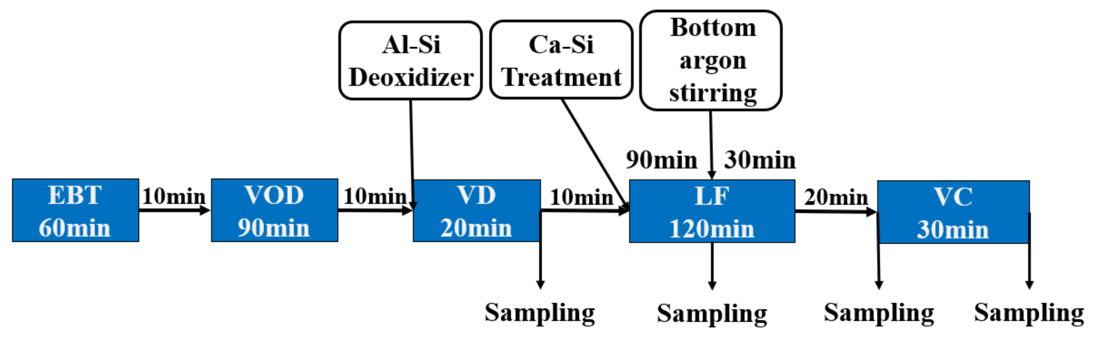
2.1. Experimental Procedures

In this paper, the actual smelting process of 15-5PH stainless steel in a steel plant in China was analyzed. This study investigates the formation mechanism of DS-type inclusions in 15-5PH stainless steel castings. The particular steelmaking process route of 15-5PH stainless steel was as follows: eccentric bottom-tapping electric arc furnace (50t EBT)→vacuum oxygen decarburization unit (VOD)→vacuum degasser (VD)→ladle furnace (LF)→vacuum casting (VC), and the process flow diagram is shown in Figure 1. The molten steel was poured into the ladle after the scrap and alloy were melted in the alloy melting furnace. The decarburization was carried out at the VOD station. After vacuum oxygen decarburization was completed, its device was turned on to add Al-Si alloy to the ladle. And then increasing the bottom blowing argon flow rate to strongly stir the molten steel in the ladle. After 10 min, lime and fluorite were added to make slag, then vacuum decarburization began for VD treatment. After VD treatment was finished, Ca-Si alloy was added into the ladle and argon was injected to improve the removal rate of inclusions. When the chemical composition and temperature were suitable, the ladle was transported to the vacuum casting platform for ingot casting. The VD-end samples were collected after VD treatment. LF-end samples were sampled from the ladle after calcium treatment and argon injection. VC-onset samples were collected before vacuum casting. The ingot casting sample was taken from the vacuum casting to complete the ingot. A schematic of the sampling positions is shown in Figure 1.

2.2. Analysis of Steel and Inclusion Composition

The steel samples were polished by machining off the surface for chemical analysis. Cylinders (φ5 × 7 mm) were machined to measure the total oxygen content, which was tested by the inert gas fusion-infrared absorptiometry method (EMGA-830, Horiba, Kyoto, Japan). The Al, Ca, and Mg contents were analyzed by inductively coupled plasma optical emission spectrometry (iCAP RQ, Thermo, Massachusetts, USA) (ICP-OES). The C and S contents were determined by a high-frequency infrared carbon and sulfur analyzer (Type EMIA-920V2, HORIBA, Kyoto, Japan). The remaining alloying element contents were determined by the alkali fusion acid dissolution method. Then, inductively coupled plasma atomic emission spectrometry (iCAP RQ, Thermo, Massachusetts, USA) (ICP-OES,) was used for analysis. The composition of the specimens is listed in Table 1.
The surface of the steel samples used for inclusion analysis (10 mm × 10 mm × 10 mm) was polished with SiC paper up to 2000 mesh followed by a 2.5-μm polishing agent. The morphology and composition of non-metallic inclusions on the mirror-polished surface of the steel samples were analyzed by means of automatic scanning electron microscopy (EVO18-INCAsteel, Caisi Company, Obercohen, Germany) (SEM) combined with energy dispersive X-ray spectroscopy (FEI, Hilbert, Oregon, USA) (EDS). The size of the inclusions was defined as the maximum diameter. To accurately understand the size distribution of inclusions, the steel samples were analyzed using an automatic scanning analysis system with a minimum size set to 1 μm, because the interaction volume may spread to the steel and excite electrons from the environment around the inclusions with diameters of less than 1 μm.

3. Results and Discussion

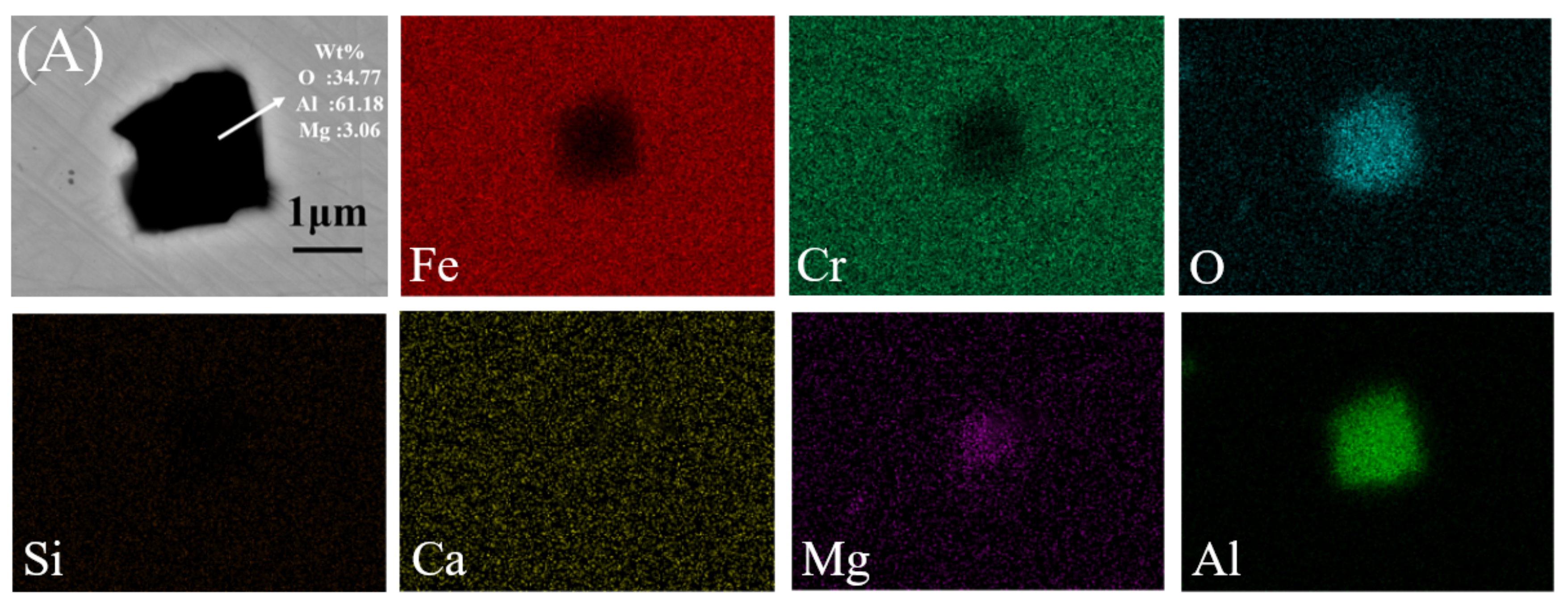
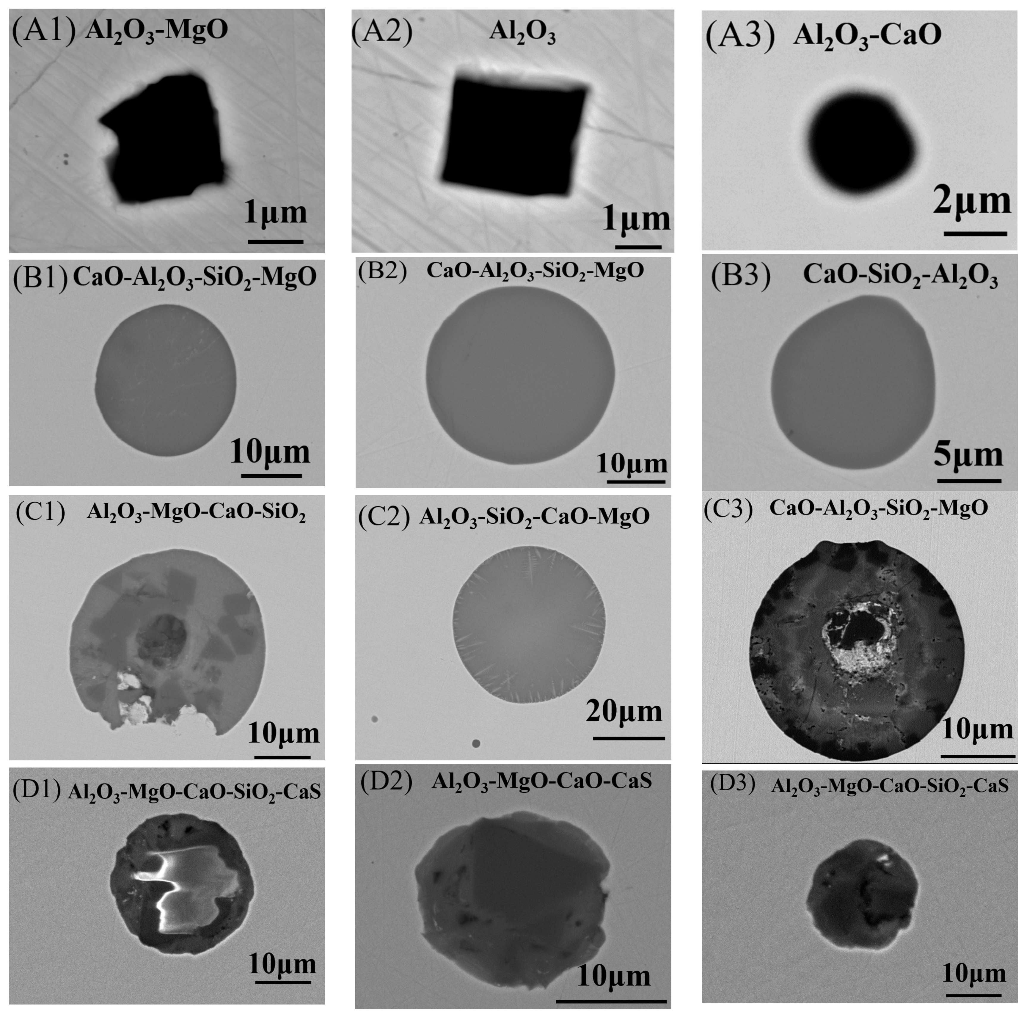
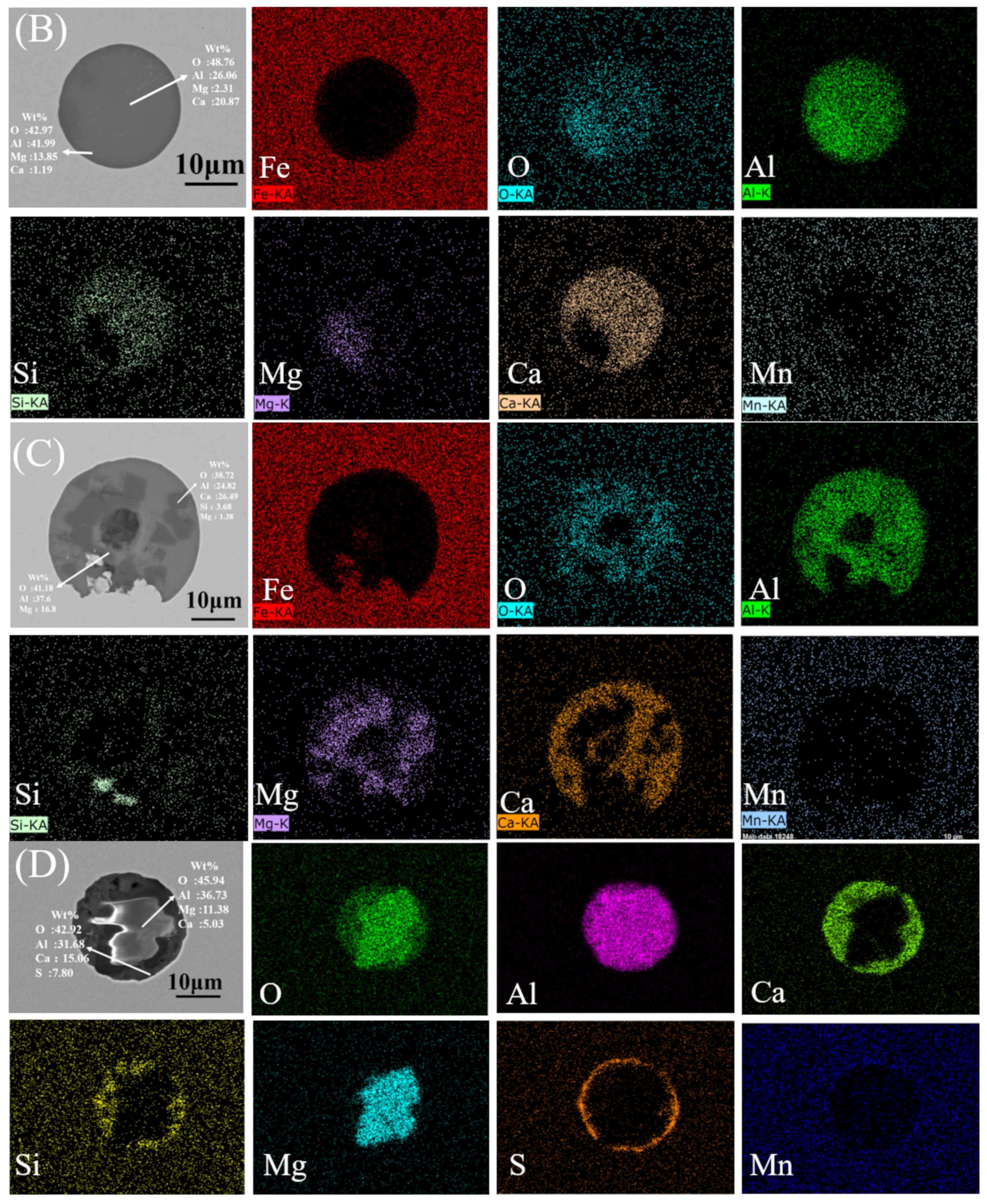
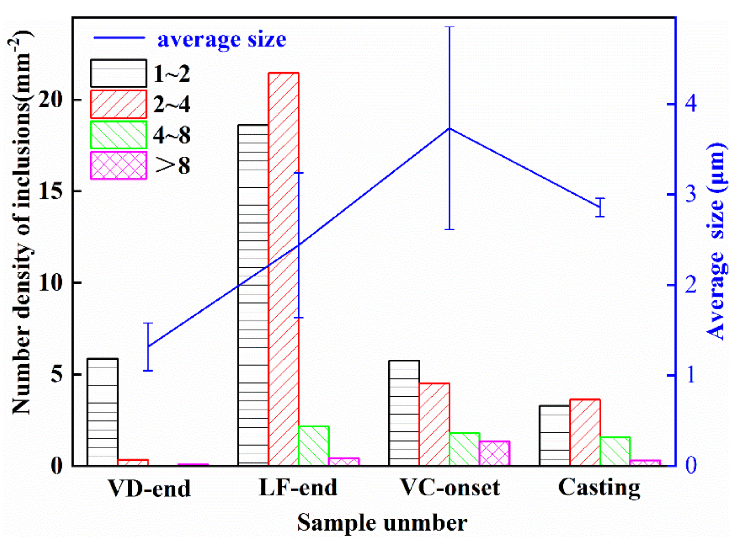
3.1. Inclusion Characteristics

Nearly 30 inclusions were selected for characterization from each sample collected at different stages. The typical inclusion types in sample VD-end were Al2O3–MgO and Al2O3 due to the addition of Si-Al alloy deoxidization at the VD station, as shown in Figure 2A. The Al2O3 content in inclusions was much higher than that of MgO. The elemental distribution of a typical inclusion in the VD-end samples is shown in Figure 3A (the number next to the inclusion represents the mass percentage determined by EDS analysis). It can be seen that the inclusions in the VD-end mainly contain Al2O3 and MgO. The type of inclusions in sample LF-end were basically the same as those in sample VC-onset, as shown in Figure 2B. Figure 3B shows the elemental distribution of the homogeneous CaO–Al2O3–SiO2–MgO inclusions in the LF-end sample. From the spherical shape of these inclusions, it was obvious that these inclusions were mainly liquid oxides. Compared with sample VD-end, CaO-type inclusions among the inclusions increase, which was mainly due to the addition of Ca–Si wire in the LF process. This results in an increase in Ca content of the molten steel and an increase in size. The main inclusion type before vacuum casting contains an Al2O3-MgO core surrounded by calcium aluminate, as shown in Figure 2C. Figure 3C shows complex inclusions of calcium aluminates growing outside multiple cores in the sample VC-onset.
After vacuum casting, there were a large number of CaO–Al2O3–SiO2–MgO–CaS inclusions and a small amount of Al2O3–MgO–MnS inclusions. SEM images of typical inclusions are shown in Figure 2D. Figure 3D shows the elemental distribution of a typical CaO–Al2O3–SiO2–MgO–CaS inclusion. It can be observed that the compositions of the inclusions were heterogeneous. The typical inclusions were CaS wrapped outside CaO–Al2O3–SiO2–MgO or Al2O3–MgO. CaS was formed mainly due to the decrease in solubility and subsequent precipitation during the solidification process. Finally, a large number of CaO–Al2O3–SiO2–MgO–CaS composite inclusions with nearly circular shapes were generated with Al2O3–MgO as the core.
Figure 4 shows the size distribution measurement results. Inclusions were classified according to size: 1–2, 2–3, 3–4, 4–8, and >8 μm. The inclusion density in sample VD-end (after the Al-Si addition) was 6.3 inclusions per mm2 and the average inclusion size was 1.5 μm. After adding Ca-Si, the average inclusion density reached a maximum of 42.64 inclusions per mm2. This was mainly because the VD process time was too short for the deoxidation reaction to reach equilibrium; instead, equilibrium was reached at the LF. The average inclusion size reached a maximum before vacuum casting, and the average inclusion size was 3.57 μm. The increase of average size of inclusions was mainly caused by the growth and aggregation of inclusions. With the flotation and removal of inclusions in the casting process, the density was reduced to 8.78 inclusions per mm2 and the average size was reduced to 3.13 μm. The error analysis results in Figure 4 show that the deviation of inclusion size for the VC-onset sample is the largest, which was due to the existence of the large number of large size inclusions in the VC-onset sample, which further indicates that the inclusion size of VC-onset sample is the largest in the smelting process of 15-5PH stainless steel.
A ternary diagram of CaO–MgO–Al2O3 calculated by FactSage 8.0 software (Thermfact/CRCT, Montreal, Canada and GTT-Technologies, Aachen, Germany)was used to describe the evolution of inclusions after addition Al-Si, Ca-Si alloys and ingot casting, as shown in Figure 5. Isothermal temperature of diagrams were 1873 K and the red line represents the liquid oxide phase region. As shown in Figure 5a, after adding Al-Si alloy, the inclusions were mainly located near the spinel. There were also a small amount of inclusions in or near the liquid oxide phase region. As shown in Figure 5b,c, after the addition of Ca-Si alloy, the mass fraction of CaO in the inclusions increases gradually, so that the spinel is modified into liquid or dual-phase inclusions. The size of inclusions is also increasing, and the size of inclusions in the VC-onset samples reached the maximum size. During the process of vacuum casting, inclusions in molten steel move to the corner of Al2O3, as shown in Figure 5d. This means that the mass fraction of Al2O3 in inclusions increases and the average particle size of the inclusions decreases.

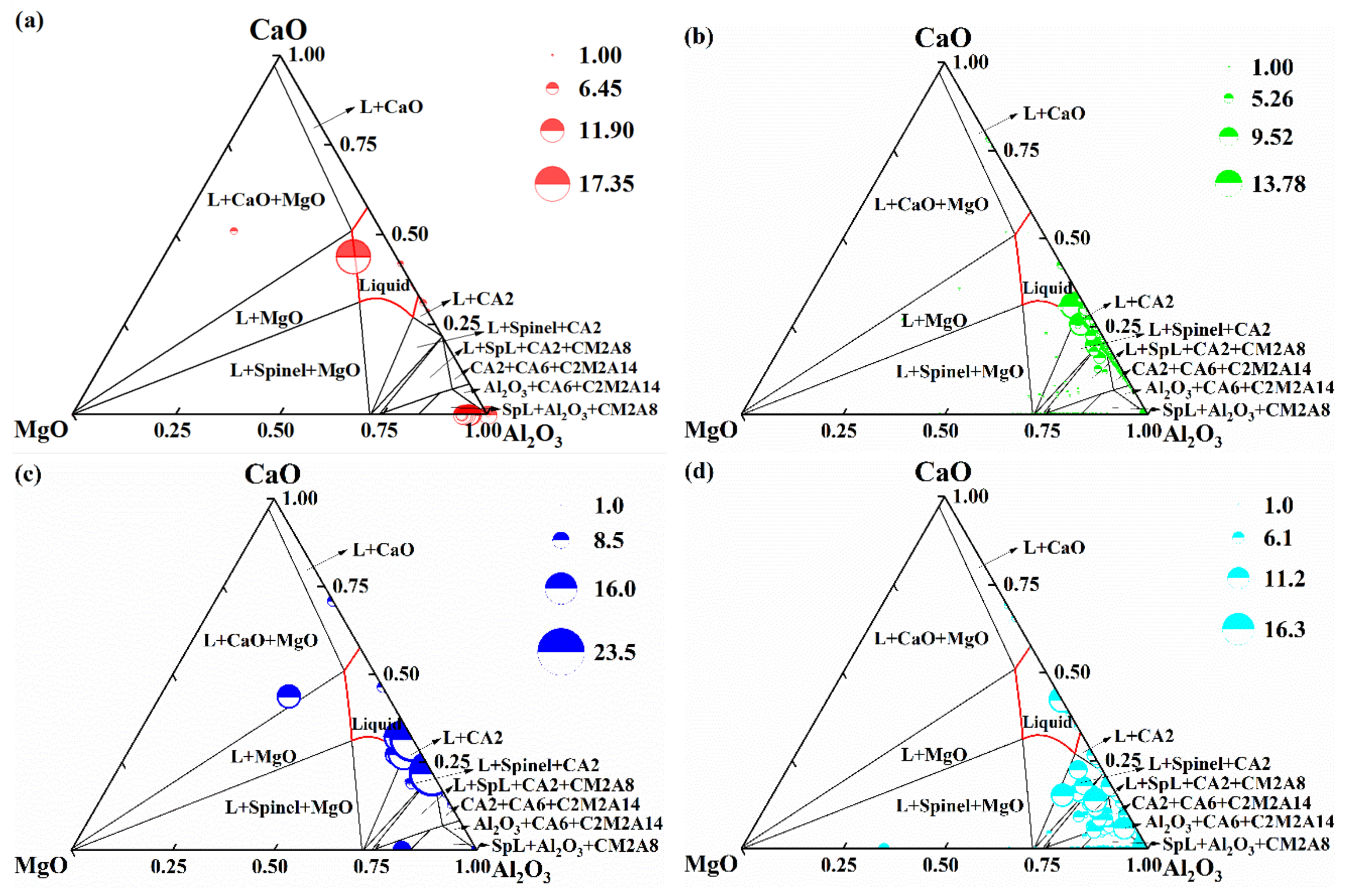
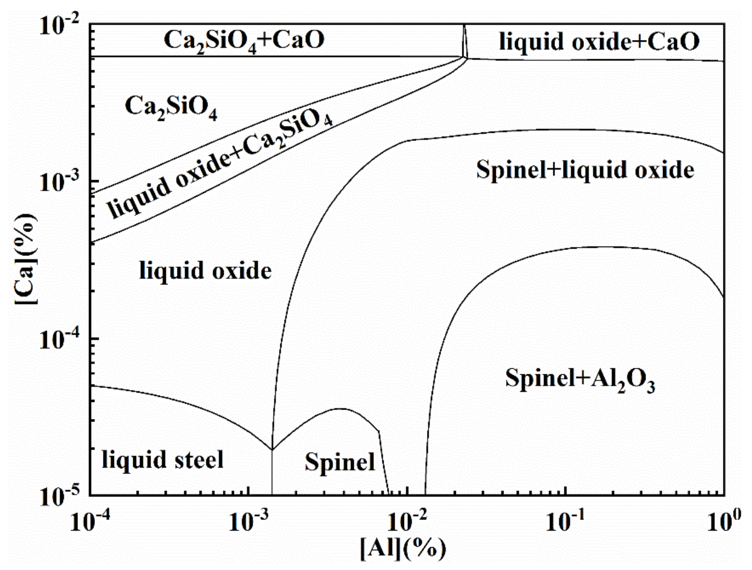
3.2. Thermodynamic Calculation of Inclusion Formation

Based on the observation of inclusion evolution, it was necessary to investigate the thermodynamics of inclusion evolution during plant trials to study the formation mechanism of DS-type inclusions.
To investigate the inclusion evolution mechanism after Al addition, the stable phase diagram of the Al-Mg-O system in 15-5PH stainless steel at 1873 K was calculated using FactSage software (version 8.0). As shown in Figure 6, the Al content ranged from 1 ppm to 1%, and Mg from 0.1 to 100 ppm. Three oxide regions can be identified in the diagram: Al2O3, spinel, and MgO·Al2O3 was modified to spinel inclusions even at Mg contents as low as 1 ppm. When [Als] was 0.005%, the content of MgO corresponding to the stable existence interval of MgO·Al2O3 was 0.8~9 ppm. In the experiment, [Als] was 0.005% and [Mg] was 0.0003%, hence MgO·Al2O3 was the stable phase, which indicates that it was easy to generate the stable MgO·Al2O3 spinel during 15-5PH stainless steel making process.
To study the inclusion evolution after Ca treatment, the stability phase diagram of the Al–Ca-50 ppm O-5ppm Mg system in 15-5PH stainless steel at 1873 K was calculated using FactSage software. As shown in Figure 7, the Al content changed from 1 ppm to 1%, and the Ca content changed from 0.1 to 100 ppm. When Ca content increases in molten steel, the liquid oxide area becomes increasingly larger. Adding more Al content in the molten steel can reduce the formation of liquid oxide. After the Ca-Si addition, the Ca content changed from 4 to 19 ppm. Wang et al. [19] reported that nearly 18 ppm Ca was needed for inclusion modification if the Al content was less than 0.01% with 50 ppm O. This is consistent with the results presented in this paper. The location of the melt composition moved from the dual-phase region to the liquid oxide region, similar to the VD-end and LF-end locations. The oxides were liquid or dual-phase CaO–MgO–SiO2–Al2O3. Meanwhile, the typical inclusion in the VC-onset sample was the dual-phase CaO–MgO–SiO2–Al2O3 inclusion, as shown in Figure 2C(1–3) and Figure 3C. Through Figure 7, it can be better analyzed that the formation of dual phase CaO–MgO–SiO2–Al2O3 inclusion in the VC-onset sample was mainly due to the continuous reaction of Ca in molten steel with inclusions and the formation of CaO at the periphery of inclusions, thus reducing the melting point of the inclusions. Therefore, reducing the content of Ca in molten steel and increasing the content of Als appropriately will balance the inclusion type to spinel and Al2O3 solid phase composition. This could effectively reduce the formation of DS-type inclusions.
To further clarify the formation mechanism of DS-type inclusions, the equilibrium precipitation diagram of the 15-5PH alloy was also calculated using FactSage. The steel composition of the VC-onset sample was used as the initial composition and the initial temperature was 1873 K. As shown in Figure 8, liquid steel began to solidify at 1723 K. Liquid steel completely disappeared at 1663 K. As the temperature decreased, the solubility of oxygen and aluminum decreased as well. As shown in Figure 8, CaS was generated at 1600 K, which was the main cause for the formation of CaS around CaO-MgO-SiO2-Al2O3. Furthermore, the mass fraction of Al2O3 increased from 2 × 10⁻⁸ to 6 × 10⁻⁸ before solidification and increased from 6 × 10⁻⁸ to 7 × 10⁻⁷ during solidification. This indicates that the DS-type inclusions were formed during casting. Meanwhile, the average inclusion size in the casting sample was smaller than that in the VC-onset sample. It could be speculated that the vacuum casting process was conducive to inclusion removal, which is consistent with the oxygen content change shown in Table 1. In addition, the slow cooling rate and long solidification time contributed to the formation of these. Adding more Al content and less Ca content was effective in reducing the formation of DS-type inclusions. Controlling the [Ca] and [Mg] contents can not only reduce the number of D class inclusions, but also inhibit the inclusion growth. This had a significant effect on improving the fatigue properties of 15-5PH stainless steel [20,21].

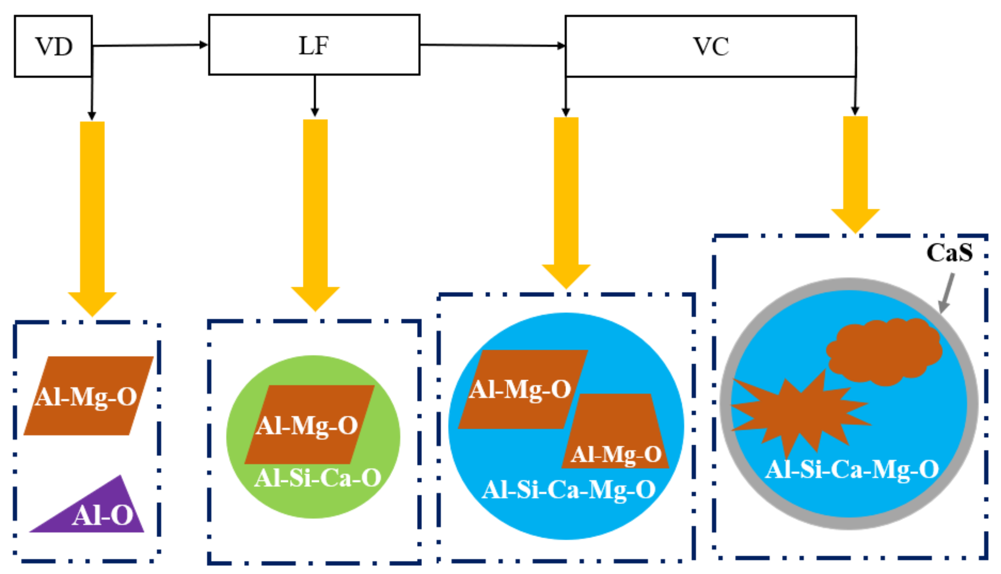
3.3. DS-Type Inclusion Formation Mechanisms and Controlling Methods

Accordingly, DS-type inclusions were likely formed by the agglomeration of small inclusions. These large inclusions become more complex as they increase in size. At the beginning of the process, the inclusions were simply Al2O3 and MgO–Al2O3. However, when the [Ca] content increases, the inclusions transform to Al2O3 and MgO–Al2O3 as the core with SiO2–CaO–Al2O3 as the coating layer and are then further transformed into the morphology that the core was formed in as MgO–Al2O3 and the outer layer was constituted by Al2O3–CaO–SiO2–MgO–CaS. The process development for the DS-type inclusions is illustrated in Figure 8. These reactions occur during the melting process in the following six stages:
(1) The main reactions after Al addition in molten steel: [Al] and [O] generate Al2O3.
(2) MgO could be reduced by [Al] at the metal-slag and metal-lining interfaces to which [Mg] can form, as shown in Equation (1). With more Mg content added, Al2O3 mainly transforms into one type: Al2O3·MgO,
(3) As the [Ca] and [Si] content continues to increase, the inclusions were then changed into CaO–MgO–Al2O3 inclusions (Equation (2)). However, because MgO·Al2O3 spinel has a high melting point, the diffusion and infiltration of [Ca] takes time, so it was difficult for the spinel core to be transformed completely in this stage.
(4) CaO–Al2O3–SiO2 would appear by adding excessive [Ca], [Al], [Si], and [O] (Equation (3)), they, together with CaO-MgO-Al2O3, tended to produce large inclusions, and then the CaS forms as a shell. DS-type inclusions were generated if the inclusion sizes exceed 13 μm. A diagram of this mechanism is shown in Figure 8.
In the solidification and cooling processes, as the temperature decreases, the remaining inclusions will precipitate into solid phases in the matrix of type I inclusions (typical inclusions were liquid or dual-phase Al2O3-CaO-SiO2-MgO.) and finally convert to DS-type inclusions. The thermodynamic calculation in Figure 9 also demonstrates this mechanism.
2[Al] + 3(MgO) = (Al2O3) + 3[Mg]
[Ca] + [O] + [Si] + MgO·Al2O3 = Al2O3·MgO·CaO·SiO2
[Ca] + [Al] + [Si] + [O] = CaO·Al2O3·SiO2

4. Conclusions

The 15-5PH stainless steel produced by the EBT→VOD→VD→LF→VC process was experimentally studied. By analyzing the morphology, size, composition, and distribution of inclusions in the refining and vacuum casting processes, and discussing the formation thermodynamics of typical DS-type inclusions, the following conclusions can be drawn:
(1) Al2O3–CaO–SiO2–MgO–CaS DS-type inclusions were formed with a size greater than 20 μm.
(2) After the Si-Al addition in the VD, typical inclusions were spinel or Al2O3. After the Ca-Si addition in the LF, typical inclusions were liquid or dual-phase Al2O3-CaO-SiO2-MgO. However, with decreasing temperature during casting, the mass fraction of Al2O3 in the inclusions increased because of the decreasing solubility of oxygen and aluminum. During the solidification process, owing to the segregation of S and the decrease in solubility, a CaS shell formed around the CaO-Al2O3-SiO2-MgO spherical inclusions, resulting in Al2O3-CaO-SiO2-MgO-CaS inclusions in the final casting.
(3) An increase in [Ca], [Mg], and [O] content promotes the formation of DS-type inclusions. To control DS-type inclusions, reducing the content of Ca in molten steel and increasing the content of Als appropriately. Slag and refractory composition control are also necessary, because the [Mg] contents mainly comes from the slag and lining.

Author Contributions

Conceptualization and writing, Z.Z.; original draft preparation, Z.Z., Y.Z.; methodology and formal analysis, Z.Z., W.Z., Y.Z., R.S., G.C.; validation and formal analysis, Z.Z., Y.Z., G.C.; supervision, Z.Z., Y.Z. All authors have read and agreed to the published version of the manuscript.

Funding

This work was supported by the National Natural Science Foundation of China (U1960201) and the National Key R&D Program of China (2019YFC1905701).

Data Availability Statement

Not applicable.

Acknowledgments

The authors gratefully express their appreciation towards the National Nature Science Foundation of China, the State Key Laboratory of Advanced Metallurgy at University of Science and Technology Beijing (USTB), and CITIC Heavy Machinery Co., Ltd for supporting this work.

Conflicts of Interest

The authors declare no conflict of interest.

References

  1. Vengosh, A.; Jackson, R.B.; Warner, N.; Thomas, H.; Andrew, K. A critical review of the risks to water resources from unconventional shale gas development and hydraulic fracturing in the United States. Environ. Sci. Technol. 2014, 48, 8334–8348. [Google Scholar] [CrossRef] [PubMed]
  2. Zhou, S.; Zhou, H.; Hua, J. Study on Influence of Material on Self-Reinforcing Performance of Pump Head of Ultra-High Pressure Fracturing Pump. Mech. Des. Manuf. 2010, 7, 67–68. [Google Scholar]
  3. Zhang, S. Study on Crack Propagation and Fatigue Life of Fracturing Pump Head; Yangtze University: Jingzhou, China, 2018. [Google Scholar]
  4. Wang, Z.; Chen, L.; Zhang, X. Fatigue Life Analysis of Drilling Pump Valve Box. J. Chongqing Univ. Sci. Technol. 2014, 16, 77–79. [Google Scholar]
  5. Park, J.H.; Kang, Y. Inclusions in Stainless Steels—A Review. Steel Res. Int. 2017, 88, 1700130. [Google Scholar] [CrossRef]
  6. Li, J.; Cheng, G.; Ruan, Q.; Pan, J.; Chen, X. Evolution Mechanism of Oxide Inclusions in Titanium-Stabilized AISI 443 Stainless Steel. Met. Mater. Trans. B 2018, 49, 2357–2369. [Google Scholar] [CrossRef]
  7. Park, J.H. Formation Mechanism of Spinel-Type Inclusions in High-Alloyed Stainless Steel Melts. Met. Mater. Trans. B 2007, 38, 657–663. [Google Scholar] [CrossRef]
  8. Park, J.H.; Todoroki, H. Control of MgO·Al2O3 Spinel Inclusions in Stainless Steels. ISIJ Int. 2010, 50, 1333–1346. [Google Scholar] [CrossRef] [Green Version]
  9. Yang, S.; Wang, Q.; Zhang, L.; Li, J.; Peaslee, K. Formation and Modification of MgO·Al2O3-Based Inclusions in Alloy Steels. Met. Mater. Trans. B 2012, 43, 731–750. [Google Scholar] [CrossRef]
  10. Pan, C.; Hu, X.; Lin, P.; Chou, K. Evolution of Inclusions after Cerium and Titanium Addition in Aluminum Deoxidized Fe-17Cr-9Ni Austenitic Stainless Steel. ISIJ Int. 2020, 60, 1878–1885. [Google Scholar] [CrossRef]
  11. Li, J.; Cheng, G.; Ruan, Q.; Pan, J.; Chen, X. Evolution behaviour of nonmetallic inclusions in Ti-bearing 11Cr stainless steel with calcium treatment. Ironmak. Steelmak. 2020, 47, 31–39. [Google Scholar] [CrossRef]
  12. Li, J.; Cheng, G.; Ruan, Q.; Li, J.; Pan, J.; Chen, X. Evolution Mechanism of Inclusions in Al-killed, Ti-bearing 11Cr Stainless Steel with Ca Treatment. ISIJ Int. 2018, 58, 1042–1051. [Google Scholar] [CrossRef] [Green Version]
  13. He, Q.X.; Sun, S.Q. Introduction to Steel-Determination of Content of Nonmetallic Inclusions-Micrographic Method Using Standards Diagrams GB/T 10561–2005. Ptca (Part: Aphystest) 2007, 43, 103–107. [Google Scholar]
  14. Wu, H.; Li, Q.; Wei, C.; Wang, Z. Study on the behaviour of DS-Class inclusions in advanced bearing steel. Met. Res. Technol. 2019, 116, 223. [Google Scholar] [CrossRef] [Green Version]
  15. Dehua, L.; Qinghua, C. Cause Analysis of Large Particle Inclusions (Ds) in GCr15 Steel. Steelmaking 2007, 2, 21–24. [Google Scholar]
  16. Chen, R.; Chen, Z.; Xu, Y. In-situ observation of behaviors of inclusions in bearing steel. J. Iron Steel Res. 2015, 27, 48–53. [Google Scholar]
  17. Jiang, M.; Wang, X.-H.; Pak, J.-J.; Yuan, P. In Situ Observation on Behaviors of CaO-MgO-Al2O3-SiO2 Complex Inclusions at Solid–Liquid Interface of Low-Oxygen Special Steel. Met. Mater. Trans. B 2014, 45, 1656–1665. [Google Scholar] [CrossRef]
  18. Shin, J.H.; Park, J.H. Effect of CaO/Al2O3 Ratio of Ladle Slag on Formation Behavior of Inclusions in Mn and V Alloyed Steel. ISIJ Int. 2018, 58, 88–97. [Google Scholar] [CrossRef] [Green Version]
  19. Wang, Q.; Wang, L.; Zhai, J.; Li, J.; Chou, K. Calcium Treatment for FeSi-killed Fe-13 Pct Cr Stainless Steel with Various Top Slag Compositions. Met. Mater. Trans. B 2018, 49, 325–333. [Google Scholar] [CrossRef]
  20. Escobar, J.D.; Faria, G.; Maia, E.; Oliveira, J.; Boll, T.; Seils, S.; Mei, P.; Ramirez, A. Fundamentals of isothermal austenite reversion in a Ti-stabilized 12cr-6 Ni-2 Mo super martensitic stainless steel: Thermodynamics versus experimental assessments. Acta Mater. 2019, 174, 246–259. [Google Scholar] [CrossRef]
  21. Martin, A.C.; Oliveira, J.P.; Fink, C. Elemental Effects on Weld Cracking Susceptibility in AlxCoCrCuyFeNi High-Entropy Alloy. Met. Mater. Trans. A 2020, 51, 778–787. [Google Scholar] [CrossRef]
Figure 1. Schematic of sampling locations.
Metals 11 01129 g001
Figure 2. Morphology and main components of typical inclusions in samples (A1A3) VD-end, (B1B3) LF-end, (C1C3) VC-onset, and (D1D3) Casting.
Metals 11 01129 g002
Figure 3. Elemental distribution maps of typical inclusions at each stage. (A) Typical Al2O3–MgO inclusion in sample VD-end, (B) typical CaO–Al2O3–SiO2–MgO inclusion in sample LF-end, (C) Typical CaO–Al2O3–SiO2–MgO inclusions in sample VC-onset, and (D) typical CaO–Al2O3–SiO2–MgO–CaS inclusions in sample Casting.
Metals 11 01129 g003aMetals 11 01129 g003b
Figure 4. Density and average size of oxides in the steel samples.
Metals 11 01129 g004
Figure 5. Main composition distribution of inclusions in different stages. (a) VD-end, (b) LF-end, (c) VC-onset, and (d) Casting.
Metals 11 01129 g005
Figure 6. Calculated phase stability diagram of the Mg–Al–O system with iso-oxygen contours in 15-5PH (14.5%Cr-5.2%Ni-3%Cu-0.7%Mn-0.4%Si-0.3%Mo-0.2%Nb-0.05%C-Fe) stainless steel at 1873 K after Al addition.
Metals 11 01129 g006
Figure 7. Stability phase diagram of Ca-Al-50 ppm O-5 ppm Mg in 15-5PH stainless (14.5%Cr-5.2%Ni-3%Cu-0.7%Mn-0.4%Si-0.3%Mo-0.2%Nb-0.05%C-Fe) steel at 1873 K after Ca treatment.
Metals 11 01129 g007
Figure 8. Equilibrium precipitation of inclusions during solidification of 15-5PH stainless (14.5%Cr-5.2%Ni-3%Cu-0.7%Mn-0.4%Si-0.3%Mo-0.2%Nb-0.05%C-Fe) with the VC-onset chemistry.
Metals 11 01129 g008
Figure 9. DS-type inclusion evolution diagram with refining processes.
Metals 11 01129 g009
Table 1. Chemical composition of the steel samples (mass percent).
Sample NoCSiMnSCrNiCuAlsCa
ppm
Mg
ppm
O
ppm
Fe
VD-end0.0360.30.690.00614.55.12.90.0056<5(4)<5(2)122bal
LF-end0.030.560.610.00714.55.12.90.0119554bal
VC-onset0.050.40.660.00814.45.12.90.0062115.440bal
Casting0.050.40.710.00614.55.12.90.00547.6<5(4)29bal
Publisher’s Note: MDPI stays neutral with regard to jurisdictional claims in published maps and institutional affiliations.

