Abstract
To quantify the influence of temperature uncertainty on thermal fatigue life prediction of a shot sleeve in an injection mechanism, an uncertainty analysis method based on a Kriging surrogate model and Monte Carlo simulation (MCS) was proposed. The training samples of the surrogate model were obtained by a finite element simulation, and the response relationships between input variables, such as pouring and preheating temperature, and target variables, such as strain and stress, were constructed by the Kriging surrogate model. The input variables were sampled by the MCS, and the predicted stress and strain parameters were combined with the modified universal slope equation to predict the thermal fatigue life of the shot sleeve. The statistical characteristics of the predicted life were obtained. The comparative analysis results indicate that the predicted life considering temperature uncertainty is more accurate than the deterministically predicted value.
1. Introduction
Squeeze casting is a technology with high efficiency, high yield, and precise forming that is widely used in machinery, automobiles, household appliances, and aerospace industries [1,2]. The injection mechanism is a key component of a squeeze casting machine, and its reliable operation directly affects the forming quality and production efficiency of products [3,4]. During the injection process, the shot sleeve comes into contact with the high-temperature molten metal at the pouring stage, resulting in strong compression stresses on the surface, while during the injecting and cooling stages, tension stresses are generated on the surface of the shot sleeve. These repeated cycles lead to the appearance of surface thermal fatigue cracks, and thermal fatigue becomes one of the most important factors affecting the service life of the injection mechanism [5]. Little research has been conducted to predict the life of the shot sleeve; however, the shot sleeve and the die-casting die experience similar thermal cyclic loading processes, and both of them are made of H13 steel, so the thermal fatigue life of both can be predicted similarly [6,7]. For example, for the shot sleeve, Shi [8] used the universal slope equation to predict the thermal fatigue life of a horizontal shot sleeve. The strain range of the dangerous position of the shot sleeve was obtained by finite element (FE) simulation, and the predicted results were close to the actual production. For die-casting dies, Lu et al. [9] established a thermal fatigue life prediction model of H13 steel reflected by temperature differences based on the modified universal slope equation. The reliability of the model was verified by FE simulation and fatigue tests for samples; however, the equation is limited because it needs to be modified in practical application. Long et al. [10] proposed a method of directly measuring the surface temperature of a high-pressure die-casting die with an insert. Based on the temperature data collected by this method, an FE model was developed to obtain the stress fluctuation range of the die surface. The number of cycles needed for cracking to start was predicted by using the equation obtained by Long et al. [11] based on visual observation. The predicted results showed a good correlation with the actual observed results.
The above life prediction work was mainly based on FE simulations to obtain stress and strain. Accurate modeling of the injection process is the first step for short-term failure or fatigue analysis [12,13,14,15]. However, FE simulation is generally based on deterministic parameters in an ideal state, so there are always errors compared with the actual situation. These errors and uncertainties are very important reasons explaining the fluctuation in the injection process. For thermal fatigue analysis of a shot sleeve, temperature plays a direct role [16], which includes the pouring temperature and the preheating temperature of the shot sleeve. When molten metal is poured from a crucible into a shot sleeve, there will be temperature loss. There are also many uncertain factors such as inaccurate temperature measurement and uneven preheating temperature in the preheating process of a shot sleeve. However, in an FE simulation, these parameters are assumed to be definite values, which will inevitably lead to errors between the simulation and the experiment. Therefore, life prediction based on a deterministic simulation will inevitably have errors, which will directly determine the accuracy of the life prediction, and it is necessary to analyze these uncertain factors in order to achieve thermal fatigue life prediction with higher reliability [17]. Monte Carlo simulation (MCS) is one of the most commonly used methods in uncertainty analysis [18,19]. Its basic principle is to draw (pseudo-) random numbers from a set of input parameters with known distribution functions to obtain a sampled distribution of the output parameter. However, MCS requires a large number of sample points for simulation, and it is inefficient to obtain data only by FE simulation. Therefore, a Kriging surrogate model is used to approximate the FE model. The surrogate model usually refers to an approximate mathematical model that can be used to replace complex and time-consuming numerical models (e.g., FE models) in analysis and optimization design. Here, the term “surrogate model” has the same meaning as “response surface model”, “metamodel”, “approximation model”, “emulator”, etc. [20]. The Kriging model is an optimal unbiased estimation model that uses the known information of sample points near an unknown point to estimate the unknown point by linear weighting [21,22]. The Kriging model has been widely used in uncertainty modeling and parameter optimization because of its good approximation ability to nonlinear responses and useful estimation of error. For example, Gao et al. [23] utilized an MCS to generate random samples and a Kriging surrogate model to approximate a high-order flow field calculation model and successfully analyzed the influence of a blade machining error on compressor performance. Ma et al. [24] proposed an optimization method to obtain optimal electrical discharge machining (EDM) parameters. In their study, a Kriging model was built to approximate the relationship between the EDM parameters and the machining accuracy. The constraint function was the probability that the aperture gap calculated by MCS was lower than the given value. Sun et al. [25] proposed a prediction method of mechanism dynamic wear with aleatory and epistemic uncertainty. The Kriging model was applied to replace the simulated model of wear prediction, and the Improved Double-Loop Monte Carlo Sampling Approach was used to propagate the influence of parameter uncertainty on the system response in the whole time domain. You et al. [26] established a spatiotemporal Kriging model to substitute the complicated computer model, which could accurately predict the temperature at different positions of the shot sleeve, but their research did not involve parameter uncertainty.
In this study, after developing a Kriging model and MCS-based method to obtain a large number of sample points’ data, the modified universal slope equation was employed to predict the thermal fatigue life of a shot sleeve. Following statistical analysis of the predicted results, the statistical values of thermal fatigue life were obtained. Compared with the deterministic fatigue life prediction values, the statistical values should achieve higher reliability of shot sleeve.
2. Methodology
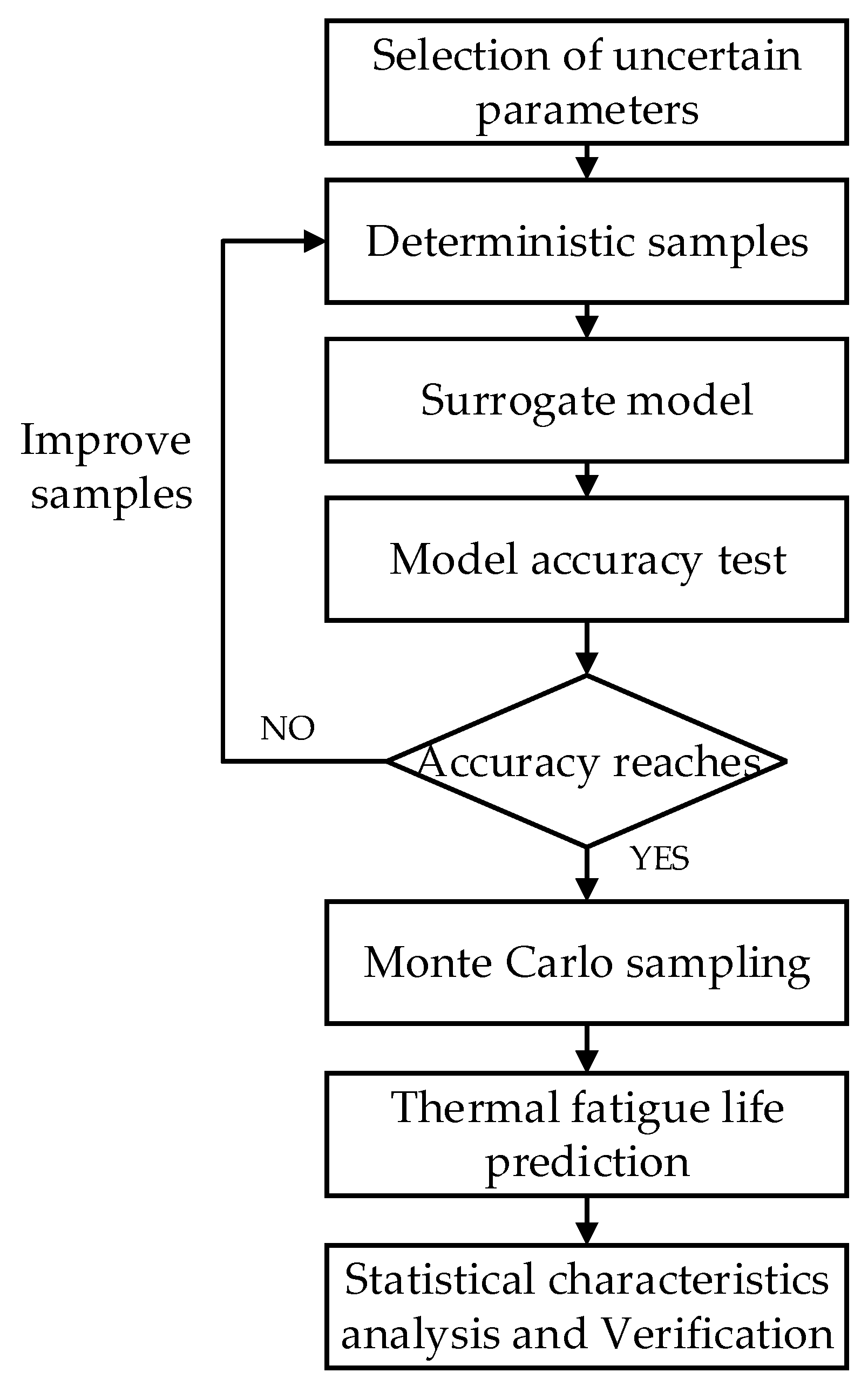
The process of uncertainty analysis was as follows:
- (1)
- Selection of uncertain parameters;
- (2)
- Sample acquisition by experiment or FE simulation;
- (3)
- Establishment of the surrogate model;
- (4)
- Accuracy testing and improvement of the surrogate model;
- (5)
- Calculation of the thermal fatigue life;
- (6)
- Statistical characteristics analysis and verification of the thermal fatigue life.
The flow chart is shown in Figure 1.
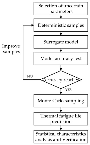
Figure 1.
Flow chart of uncertainty analysis of thermal fatigue life prediction.
2.1. Kriging Surrogate Model
The Kriging model is essentially an interpolation model, and the interpolation result is a linear weighting of known samples, which can be expressed as follows:
where y(i) represents the sample points and n is the number of sample points. The estimated values of the points to be measured could be calculated since the values of weight coefficients were obtained. Therefore, the statistical hypothesis was introduced, and the unknown function was regarded as the realization of a Gaussian static random process [21]. This static random process is defined as follows:
where β0 is used to globally approach the design space and represents the mathematical expectation of Y (x); a static random process Z (x) with a mean value of zero and a variance of σ2 is localization deviation. The correlation of sample points at different positions in the design space is expressed by the covariance:
where R (x, x′) is the correlation function, which is only related to spatial distance. When the distance is zero, the value is 1, and when the distance is infinite, the value is 0. The correlation decreases with the increase in distance. Based on the above assumptions, the unbiased condition of the Kriging model is
and the optimality condition of the minimum mean square error is
Using the Lagrange multiplier method, after derivation and solution, the Kriging prediction model was finally obtained as follows:
where R is the correlation matrix composed of correlation functions, r is the correlation matrix composed of correlation functions between unknown points and given points, and . The accuracy of the Kriging model was tested by the root mean square error (RMSE) and goodness of fit (R2) between the predicted values and the FE simulation values.
2.2. Monte Carlo Simulation
The basic principle of MCS is to randomly select a certain number of samples and calculate the response values of the response function at these sample points, so as to obtain the statistical characteristics of the response function. Because MCS requires a large number of sample points, if the sample points are substituted into the FE model to calculate the corresponding response values, it is time-consuming and inefficient. Therefore, it was necessary to establish a Kriging surrogate model to approximate the functional relationship between sample points and response values that can calculate thermal fatigue life without losing accuracy and can greatly improve calculation efficiency.
2.3. Prediction Method of Thermal Fatigue Life
In the elastic–plastic strain range, the cycle times of material failure and total strain conform to the Manson–Coffin (Equation (7)) [27,28]:
where is the total strain range; Δεe and Δεp are the elastic strain range and plastic strain range, respectively; σ′f is the fatigue strength coefficient; E is the elastic modulus; b is the fatigue strength exponent; ε′f is the fatigue ductility coefficient; and c is the fatigue ductility exponent.
The modified universal slope equation proposed by Muralidharan and Manson [29] based on the fatigue properties of 50 materials was employed to obtain the above fatigue parameters.
where is the tensile strength and , where Z is the reduction in area.
Although the modified universal slope equation is mostly based on materials mechanically tested at room temperature, it is still applicable at high temperatures. For example, Shi [8] directly used the universal slope equation to predict the thermal fatigue life of a shot sleeve; Lu et al. [9] put forward a temperature difference model based on the modified universal slope equation to predict the thermal fatigue life of high-pressure casting dies, and Hu et al. [30] realized the thermal fatigue life prediction of hot rolling work rolls based on the universal slope equation. Their predicted objects were all operating at high temperature.
As the strain–life curve is generally obtained by cyclic symmetrical loading in a laboratory, the influence of mean stress is not considered. However, the mean stress significantly impacts the fatigue life, so the Morrow method was used to modify the strain–life curve [31,32]. The universal slope equation modified by the Morrow method is:
where σm is the mean stress.
2.4. Statistical Characteristic Analysis
After obtaining the thermal fatigue life predicted by a large number of MCS sample points, the statistical characteristics of the predicted life can be analyzed. According to the central limit theorem, when the number of samples n is large enough, the output response mean approximately satisfies the normal distribution, and the confidence interval of the overall mean can be given by the following formula:
where z is the quantile of standard normal distribution, α is the standard deviation of samples, and the confidence level is expressed as 100 (1 − α). Usually, α is 0.1 or 0.05.
3. Prediction of Thermal Fatigue Life of a Shot Sleeve Considering Temperature Uncertainty
3.1. Experiment of Injection Mechanism
An experimental device was set up for a 2500 kN vertical squeeze casting machine to simulate the pouring and filling processes of the injection mechanism. An FE model was constructed and validated based on the experimental data. By strictly controlling the relevant parameters and operation process of the experimental device, it could be considered that the experimental device represented the actual injection mechanism. Figure 2 shows a photo and the structure of the squeeze casting machine.
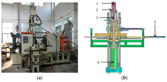
Figure 2.
Squeeze casting machine (a) picture and (b) structure. Note: 1—punch; 2—shot sleeve; 3—pushing rod; 4—pushing cylinder; 5—horizontal displacement cylinder.
The experimental device consisted of a shot sleeve, a punch, a push rod, a preheating ring, and a base, as shown in Figure 3. The punch was 63 mm in diameter and 110 mm in height. The outer diameter, inner diameter, and height of the shot sleeve were 95, 63, and 360 mm, respectively. The measuring components included thermocouples, micrometer rangefinders, and strain gauges. The materials of the punch, the shot sleeve, and the base were ductile iron, H13 steel, and 45# steel, respectively. The wall thickness of the shot sleeve was 16 mm, and the initial fit clearance was 0.1 mm. The injection mechanism was preheated to 130 °C in advance. After pouring the molten metal into the shot sleeve, the pushing rod drove the punch to move in the shot sleeve for melt filling. The whole process lasted about 140 s. Measurements were taken at different cross-sections, as shown in Figure 3a. Measurement points were selected on the shot sleeve (three temperature points—T1, T2, and T3—and three deformation points—D1, D2, and D3) and the punch (two temperature points—T4 and T5—and one deformation point, D4). The vertical distance between each measuring point on the shot sleeve was 30 mm, and the distance between the micrometer at the bottom of the shot sleeve and the lower-end face of the shot sleeve was 150 mm.
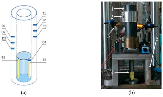
Figure 3.
Experimental device: (a) Measuring points’ positions; (b) testing photo. Note: 1—shot sleeve; 2—preheating ring; 3—micrometer rangefinder; 4—pushing rod; 5—base.
3.2. FE Simulation of Injection Mechanism
The heat transfer model of the injection mechanism is referred to in [26]. Due to the symmetry of the injection mechanism, a quarter model was used for analysis. The FE model contained 9364 nodes and 6986 hexahedron elements, as shown in Figure 4. The material of molten metal was aluminum alloy A356. The material of each part of the finite element model was consistent with that of the corresponding part in the experimental device. The material parameters of each part are listed in Table 1 [33,34].
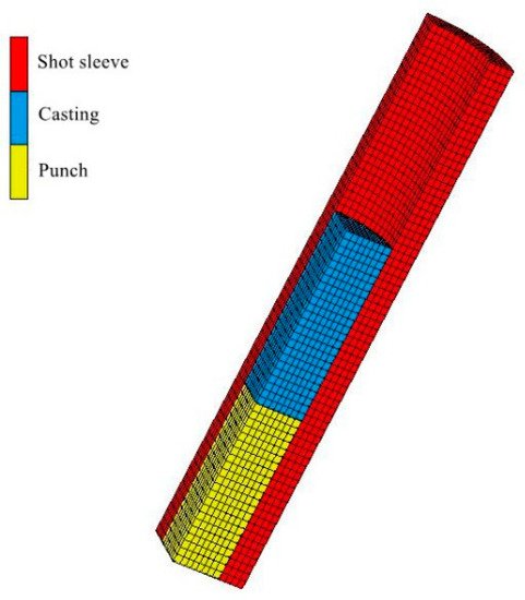
Figure 4.
FE (finite element) model of experimental device.

Table 1.
Material parameters of the parts in the FE (finite element) model.
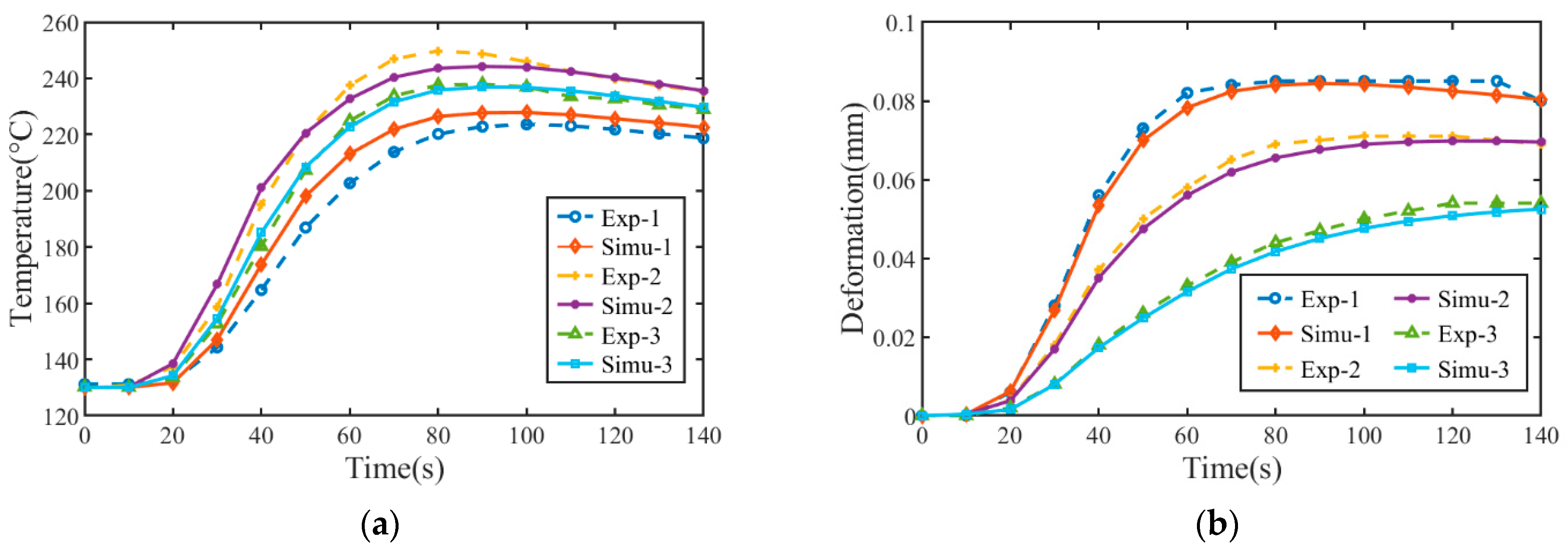
The interface heat transfer coefficient between the punch and shot sleeve was 500 W/(m2 K), that between the casting and shot sleeve was 1600 W/(m2 K), and that between the casting and punch was 450 W/(m2 K) [35,36]. Here, we took the constant values of heat transfer coefficients without considering their temperature dependence, inducing additional uncertainties. The working environment temperature was 30 °C, and the heat transfer coefficient between each component and the surrounding air was 10 W/(m2 K). Since this study aimed to predict the fatigue life of the shot sleeve, only comparisons between the experimental data and the simulation data on the shot sleeve were extracted, as shown in Figure 5. Experimental temperature points Exp1–Exp3 in Figure 5a correspond to T1–T3 in Figure 3a, respectively, and experimental deformation points Exp1–Exp3 in Figure 5b correspond to D1–D3 in Figure 3a, respectively. The positions of the corresponding simulation and experimental points are the same. The pouring temperature of the experiment and simulation was 720 °C, and the preheating temperature was 130 °C.
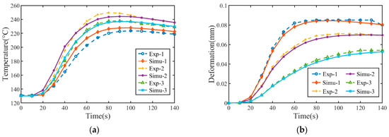
Figure 5.
Comparisons between experiment and simulation of shot sleeve: (a) temperature; (b) deformation.
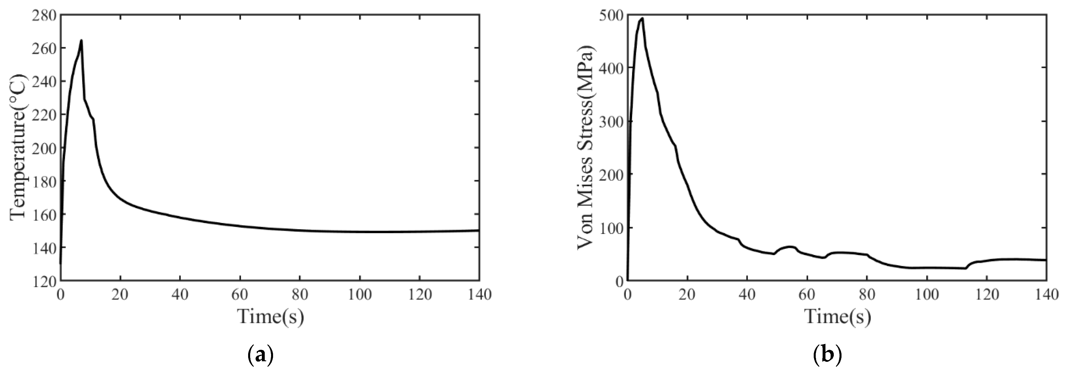
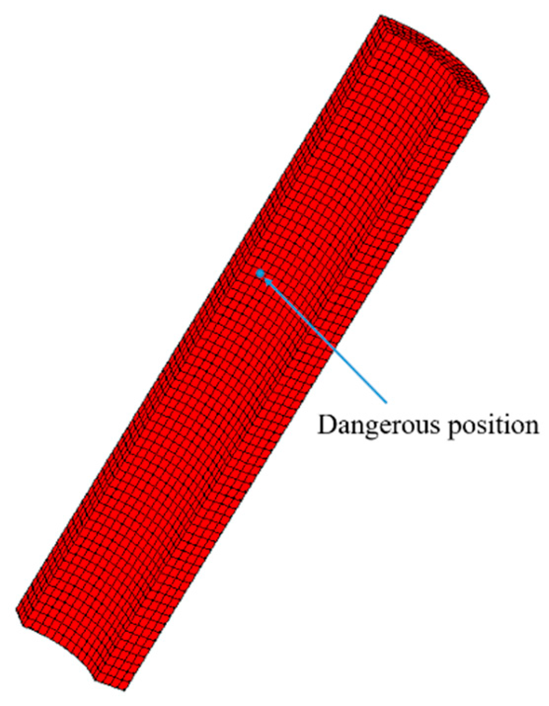
In Figure 5, for both the temperature and deformation data, the trends between the experimental and simulated results are nearly consistent, and the errors are within a reasonable range, indicating the accuracy of the FE model. Simultaneously, the errors between the simulation and experimental data reflect the uncertainty of the injection process. It should be noted that the experimental and simulated temperature values at the measuring points do not show a sudden change. As the measuring points are not in direct contact with the molten metal but are located in the middle of the wall thickness of the shot sleeve, the measured temperature values rise slowly. Figure 6 shows the temperature and stress curve at the dangerous position of the shot sleeve. The dangerous position mentioned here refers to the position where thermal fatigue was most likely to occur on the shot sleeve, as shown in Figure 7. In fact, for the surface of the shot sleeve that comes into contact with the molten metal first, the temperature will rise rapidly, so there will be a large temperature gradient and strong stress, as shown in Figure 6a. Therefore, the inner surface of the shot sleeve in contact with molten metal is a dangerous surface, and the point with the maximum Von Mises stress is a dangerous position, as shown in Figure 6b. After quenching and tempering, the yield strength of H13 should not be less than 800 MPa considering the temperature of the shot sleeve inner surface [8]. It was observed that the maximum stress did not exceed 500 MPa, which is lower than the yield strength of H13 steel, indicating elastic strain. By presetting different pouring temperatures and preheating temperatures, the response values of the dangerous position of the shot sleeve were obtained by FE simulation, which could be used to build the Kriging model.
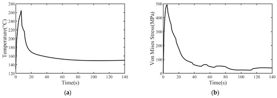
Figure 6.
Temperature and stress curve of dangerous position of shot sleeve: (a) temperature; (b) Von Mises stress.
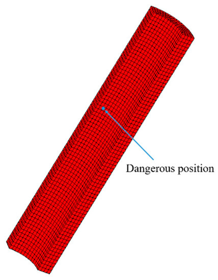
Figure 7.
Dangerous position of shot sleeve.
3.3. Data Acquisition and Kriging Model Building
Considering the working condition of the injection mechanism, the pouring temperature range of molten metal was set from 660 to 720 °C, and the preheating temperature range was set from 100 to 200 °C. The input variables of the Kriging model were two-dimensional inputs (Tc, Tm), and the corresponding responses were the strain range and mean stress of the corresponding dangerous positions. The maximum principal value of total strain was adopted for strain, and the strain range was obtained by calculating the difference between the maximum value and the minimum value. Thirty sampling points obtained by an improved Latin hypercube sampling were divided into two sets, 10 of which were used as the training set and 20 as the test set. The corresponding strain range and mean stress were calculated by FE simulation, as shown in Table 2.
Table 2.
Sample points and corresponding response values of training set.
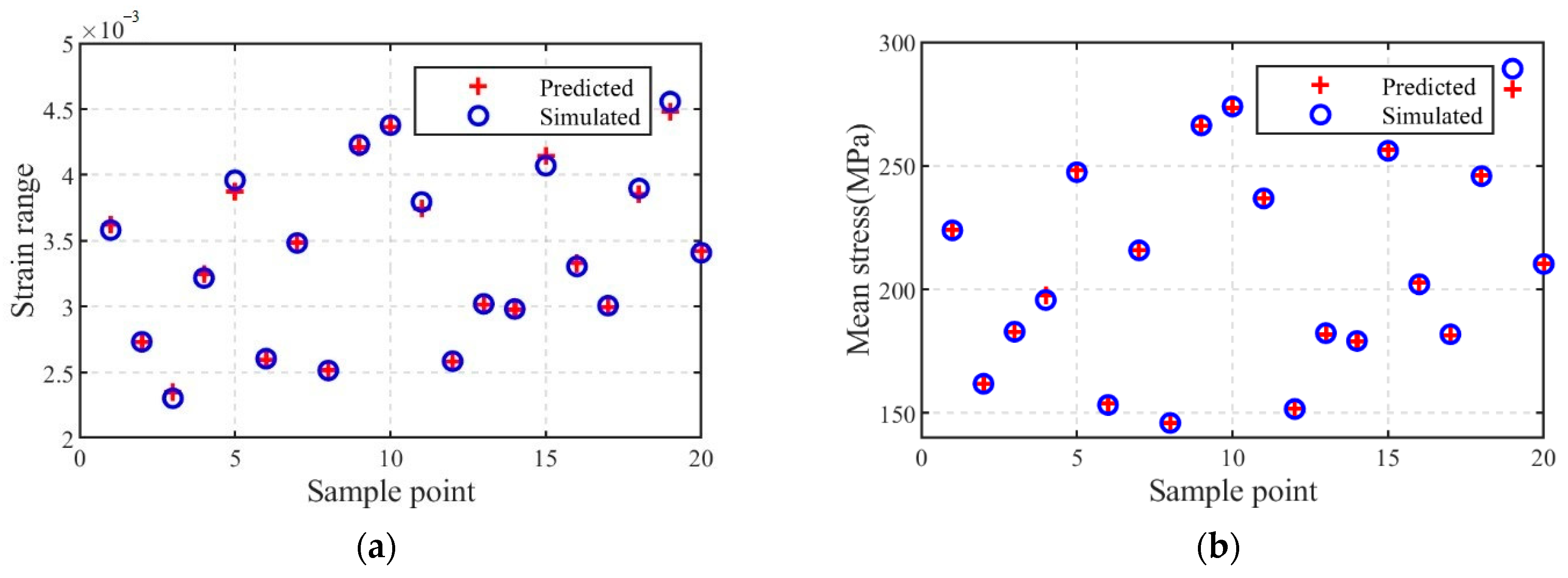
An ordinary Kriging model was established for the strain range and mean stress based on the data in Table 2, which was developed using the MATLAB DACE toolbox [37], and the correlation function adopted the Gaussian kernel function. The test set was added into the Kriging model to test the accuracy of the model. Figure 8 shows the comparisons between the FE simulation values and the predicted values obtained by the Kriging model.
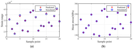
Figure 8.
Comparison between predicted values and simulation values: (a) strain range; (b) mean stress.
According to the calculation of the simulation and prediction data, the RMSE value of the strain range was 3.86 × 10⁻⁵ and the R2 value was 0.9601, and the RMSE value of the average stress was 1.96 and the R2 value is 0.9629, which show that the Kriging model has a high prediction accuracy and can be used to replace the FE model. Regarding calculation time, each FE simulation took about 30 min, while the total prediction time of the Kriging model for these 20 sample points was about 0.04 s, which was greatly reduced compared to the FE simulation.
3.4. MCS and Thermal Fatigue Life Calculation
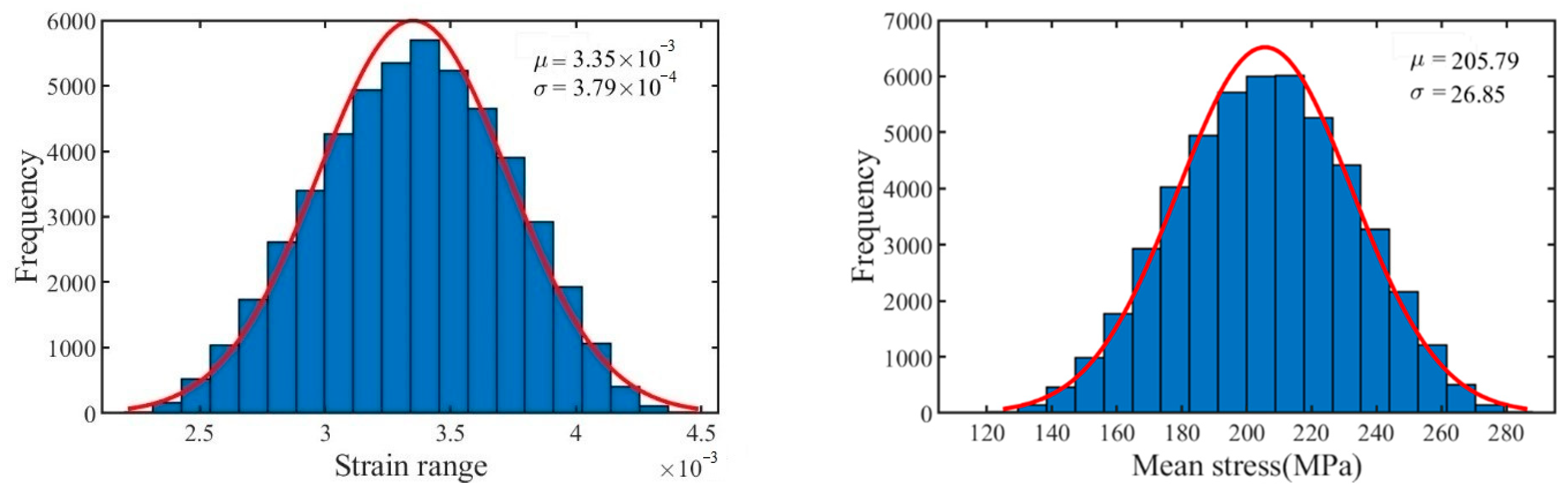
The distribution of uncertain parameters was determined for MCS. According to the operation characteristics of the injection mechanism, both the pouring temperature and the preheating temperature were assumed to follow normal distributions. The pouring temperature of the molten metal ranged from 660 to 720 °C, the preheating temperature ranged from 100 to 200 °C, and the median values were taken as the mean values. Based on the 3σ principle of normal distribution, the respective variances were calculated, and then, Tc ~ N (790,100), Tm ~ (150, 2500/9), were obtained. Monte Carlo sampling was adopted 50,000 times based on their distributions, and the obtained samples were substituted into the Kriging model to calculate the response values of the strain range and mean stress. Figure 9 shows the frequency distribution histogram of the two responses. According to the figure, the strain range and mean stress showed approximately normal distribution.

Figure 9.
Frequency distribution of response values.
As the deformation of the shot sleeve under thermal stress loading was elastic deformation, the final life prediction model was as follows:
The shot sleeve was made of H13 steel, and the maximum temperature was about 300 °C. The corresponding parameters were set as E = 203.35 Gpa and σb = 759.9 Mpa [8].
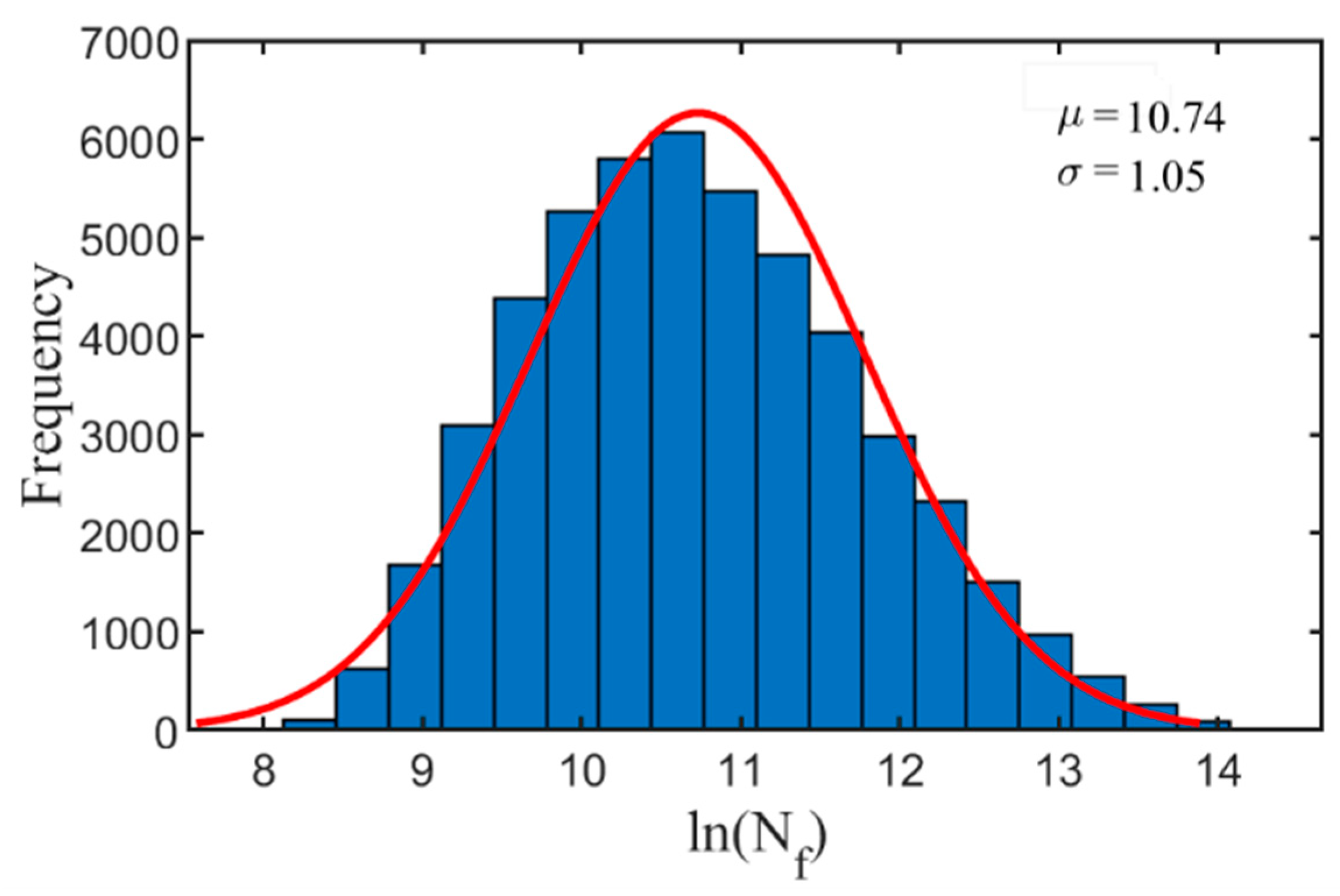
The obtained strain range and mean stress were substituted into Equation (11) to determine the thermal fatigue life of the shot sleeve. Figure 10 shows the frequency distribution histogram of the predicted life.

Figure 10.
Frequency distribution of predicted life.
4. Results and Discussion
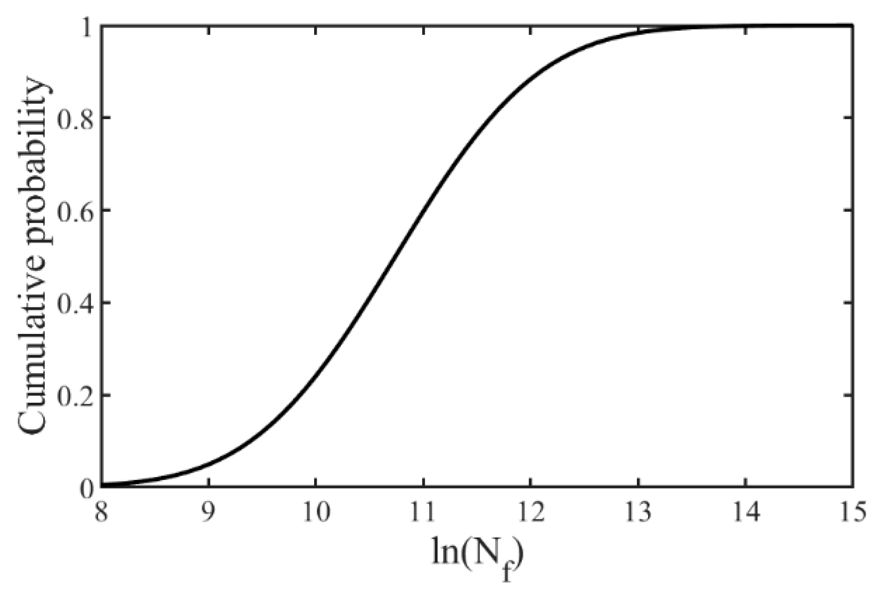
According to Table 2, the smaller the temperature difference between the pouring temperature and the preheating temperature was, the smaller the strain and stress of the corresponding dangerous parts were, and the longer the corresponding fatigue life was. As the variation range of the pouring temperature was small, appropriately increasing the preheating temperature of the shot sleeve was beneficial to prolong its service life. The statistical characteristics of the predicted thermal fatigue life were further analyzed. According to Equation (10), the ln (Nf) confidence interval at a 95% confidence level ranged from 10.518 to 10.5482, and the corresponding fatigue life was 36,975 to 38,109 cycles. The cumulative probability diagram of ln (Nf) is shown in Figure 11. The confidence interval at a 90% confidence level ranged from 7.6927 to 13.3735. Therefore, the average predicted fatigue life was about 36,975 to 38,109 cycles. The worst-case fatigue life was about 2192 cycles, which explains the significant influence of temperature uncertainty on the life of the shot sleeve. In the worst case, the shot sleeve was under the highest pouring temperature and the lowest preheating temperature, so it is necessary to reduce the temperature difference between the pouring and preheating temperatures in the injection process. In an actual production process, the service life of commercial shot sleeves investigated by [8] was generally between 20,000 and 50,000, and the fatigue life of a horizontal shot sleeve as predicted by [8] was 34,292 cycles, which is close to the average life predicted in this study.
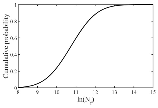
Figure 11.
Cumulative probability distribution of predicted life.
5. Conclusions
An uncertainty analysis method was proposed to quantify the influence of temperature uncertainty on the thermal fatigue life of shot sleeves. The main conclusions can be drawn as follows:
- Temperature uncertainty has an important influence on the prediction of the thermal fatigue life of shot sleeves, and considering temperature uncertainty can allow for realizing a more accurate and reliable life prediction for shot sleeves.
- When the pouring temperature ranges from 660 to 720 °C and the preheating temperature ranges from 100 to 200 °C, the predicted average thermal fatigue life of a shot sleeve is 36,975 to 38,109 cycles. The predicted results are close to those of others and are also consistent with the service life of commercial shot sleeves. In addition, reducing the difference between the pouring temperature and the preheating temperature is helpful to prolong the service life of the shot sleeve.
In this research, only temperature uncertainty is considered, but in the actual squeeze casting process, there are many uncertain factors, such as the wall thickness of the shot sleeve, the initial clearance, the injecting speed, etc. In the future, we will study how to comprehensively consider the influence of these uncertain factors on the life of the shot sleeve and the deep learning surrogate model.
Author Contributions
Conceptualization, W.P.; methodology, W.P.; validation, D.C.; writing—original draft preparation, W.P.; writing—review and editing, D.Y.; visualization, D.C.; supervision, D.Y.; funding acquisition, D.Y. All authors have read and agreed to the published version of the manuscript.
Funding
This work was financially supported by the National Natural Science Foundation of China (grant Nos. 51875209 and 51965006) and the Science and Technology Planning Project of Guangdong Province (grant No. 2021A0505030005).
Data Availability Statement
The data that support the findings of this study are available from the authors upon reasonable request.
Conflicts of Interest
The authors declare no conflict of interest.
References
- Ghomashchi, M.R.; Vikhrov, A. Squeeze casting: An overview. J. Mater. Process. Technol. 2000, 101, 1–9. [Google Scholar] [CrossRef]
- Li, Y.Y.; Zhang, W.W.; Zhao, H.D.; You, D.D.; Zhang, D.T.; Shao, M.; Zhang, W. Research progress on squeeze casting in China. China Found. 2014, 11, 239–246. [Google Scholar]
- Fiorese, E.; Richiedei, D.; Bonollo, F. Improving the quality of die castings through optimal plunger motion planning: Analytical computation and experimental validation. Int. J. Adv. Manuf. Technol. 2017, 88, 1475–1484. [Google Scholar] [CrossRef]
- Wang, Q.-L.; Xiong, S.-M. Effect of multi-step slow shot speed on microstructure of vacuum die cast AZ91D magnesium alloy. Trans. Nonferrous Met. Soc. China 2015, 25, 375–380. [Google Scholar] [CrossRef]
- Mitrović, D.; Terčelj, M.; Kastelic, S.; Primož, M. Analysis of degradation processes on shot sleeves made from new Si-Mo cast iron in aluminium high pressure die casting—A case study. Eng. Fail. Anal. 2020, 109, 104283. [Google Scholar] [CrossRef]
- Mellouli, D.; Haddar, N.; Köster, A.; Ayedi, H.F. Hardness effect on thermal fatigue damage of hot-working tool steel. Eng. Fail. Anal. 2014, 45, 85–95. [Google Scholar] [CrossRef]
- Klobčar, D.; Tušek, J. Thermal stresses in aluminium alloy die casting dies. Comput. Mater. Sci. 2008, 43, 1147–1154. [Google Scholar] [CrossRef]
- Shi, Q. Prediction of Thermal Distortion and Thermal Fatigue in Shot Sleeves. Ph.D. Thesis, The Ohio State University, Columbus, OH, USA, 2002. [Google Scholar]
- Lu, Y.; Ripplinger, K.; Huang, X.; Mao, Y.; Detwiler, D.; Luo, A.A. A new fatigue life model for thermally-induced cracking in H13 steel dies for die casting. J. Mater. Process. Technol. 2019, 271, 444–454. [Google Scholar] [CrossRef]
- Long, A.; Thornhill, D.; Armstrong, C.; Watson, D. Predicting die life from die temperature for high pressure dies casting aluminium alloy. Appl. Therm. Eng. 2012, 44, 100–107. [Google Scholar] [CrossRef]
- Long, A. Extending Life of High Pressure Die Casting Dies. Ph.D. Thesis, Queen’s University, Belfast, Northern Ireland, 2010. [Google Scholar]
- Broucaret, S.; Michrafy, A.; Dour, G. Heat transfer and thermo-mechanical stresses in a gravity casting die: Influence of process parameters. J. Mater. Process. Technol. 2001, 110, 211–217. [Google Scholar] [CrossRef] [Green Version]
- Li, C.; Thomas, B.G. Thermomechanical finite-element model of shell behavior in continuous casting of steel. Met. Mater. Trans. A 2004, 35, 1151–1172. [Google Scholar] [CrossRef]
- Koric, S.; Thomas, B.G.; Voller, V.R. Enhanced latent heat method to incorporate superheat effects into fixed-grid multiphysics simulations. Numer. Heat Tran. Part B Fundam. 2010, 57, 396–413. [Google Scholar] [CrossRef]
- Zappulla, M.L.S.; Cho, S.; Koric, S.; Lee, H.; Kim, S.; Thomas, B.G. Multiphysics modeling of continuous casting of stainless steel. J. Mater. Process. Technol. 2020, 278, 116469. [Google Scholar] [CrossRef]
- Jhavar, S.; Paul, C.; Jain, N.K. Causes of failure and repairing options for dies and molds: A review. Eng. Fail. Anal. 2013, 34, 519–535. [Google Scholar] [CrossRef]
- Bjorklund, A.E. Survey of approaches to improve reliability in lca. Int. J. Life Cycle Assess. 2002, 7, 64–72. [Google Scholar] [CrossRef]
- JCGM. Evaluation of Measurement Data-Supplement 1 to the “Guide to The Expression of Uncertainty in Measurement”—Propagation of Distributions Using a Monte Carlo Method; Joint Committee for Guides in Metrology: Geneva, Switzerland, 2008. [Google Scholar]
- Groen, E.; Heijungs, R.; Bokkers, E.; De Boer, I. Methods for uncertainty propagation in life cycle assessment. Environ. Model. Softw. 2014, 62, 316–325. [Google Scholar] [CrossRef]
- Han, Z.-H.; Görtz, S. Hierarchical Kriging Model for Variable-Fidelity Surrogate Modeling. AIAA J. 2012, 50, 1885–1896. [Google Scholar] [CrossRef]
- Sacks, J.; Welch, J.W.; Mitchell, T.J.; Henry, P.W. Design and Analysis of Computer Experiments. Stat. Sci. 1989, 4, 409–423. [Google Scholar] [CrossRef]
- Currin, C.; Mitchell, T.; Morris, M.; Ylvisaker, D. A Bayesian Approach to the Design and Analysis of Computer Experiments; Oak Ridge National Laboratory: Oak Ridge, TN, USA, 1988.
- Gao, L.M.; Cai, Y.T.; Xu, H.L.; Deng, W.M. Uncertainty analysis of machining error influence of compressor blade. J. Aerosp. Power 2017, 32, 2253–2259. [Google Scholar]
- Ma, J.; Han, X.Y.; Xu, Q.; Chen, S.Y.; Zhao, W.B.; Li, X.K. Reliability-based EDM process parameter optimization using kriging model and sequential sampling. Math. Biosci. Eng. 2019, 16, 7421–7432. [Google Scholar]
- Sun, D.Y.; Chen, G.P.; Wang, T.C.; Sun, R.J. Wear Prediction of a Mechanism with Joint Clearance Involving Aleatory and Epistemic Uncertainty. J. Tribol. Trans. 2014, 136, 41101. [Google Scholar] [CrossRef]
- You, D.D.; Jiang, X.M.; Cheng, X.Y.; Wang, X. Bayesian kriging modeling for spatiotemporal prediction in squeeze casting. Int. J. Adv. Manuf. Technol. 2017, 89, 355–369. [Google Scholar] [CrossRef]
- Coffin, L.F. A study of the effects of cyclic thermal stresses on a ductile metal. Trans. ASME 1954, 76, 931–950. [Google Scholar]
- Manson, S.S. Behavior of Materials under Conditions of Thermal Stress. NACA Rep. 1954, 7, 661–665. [Google Scholar]
- Muralidharan, U.; Manson, S.S. A Modified Universal Slopes Equation for Estimation of Fatigue Characteristics of Metals. J. Eng. Mater. Technol. 1988, 110, 55–58. [Google Scholar] [CrossRef]
- Hu, K.; Zhu, F.; Chen, J.; Noda, N.-A.; Han, W.; Sano, Y. Simulation of Thermal Stress and Fatigue Life Prediction of High Speed Steel Work Roll during Hot Rolling Considering the Initial Residual Stress. Metals 2019, 9, 966. [Google Scholar] [CrossRef] [Green Version]
- Socie, D.F.; Morrow, J. Review of Contemporary Approaches to Fatigue Damage Analysis. In Risk and Failure Analysis for Improved Performance and Reliability; Burke, J.J., Weiss, V., Eds.; Springer: Boston, MA, USA, 1980; pp. 141–194. [Google Scholar]
- Ince, A.; Glinka, G. A modification of Morrow and Smith-Watson-Topper mean stress correction models. Fatigue Fract. Eng. Mater. Struct. 2011, 34, 854–867. [Google Scholar] [CrossRef]
- Klobčar, D.; Tušek, J.; Taljat, B. Thermal fatigue of materials for die-casting tooling. Mater. Sci. Eng. A 2008, 472, 198–207. [Google Scholar] [CrossRef]
- Das, P.; Bhuniya, B.; Samanta, S.K.; Dutta, P. Studies on die filling of A356 Al alloy and development of a steering knuckle component using rheo pressure die casting system. J. Mater. Process. Technol. 2019, 271, 293–311. [Google Scholar] [CrossRef]
- Coates, B.; Argyropoulos, S.A. The Effects of Surface Roughness and Metal Temperature on the Heat-Transfer Coefficient at the Metal Mold Interface. Met. Mater. Trans. A 2007, 38, 243–255. [Google Scholar] [CrossRef]
- Helenius, R.; Lohne, O.; Arnberg, L.; Laukli, H.I. The heat transfer during filling of a high-pressure die-casting shot sleeve. Mater. Sci. Eng. A 2005, 413–414, 52–55. [Google Scholar] [CrossRef]
- Lophaven, S.N.; Søndergaard, J.; Nielsen, H.B. DACE-A Matlab Kriging Toolbox (Version 2.0): IMM-REP-2002-12; Technical University of Denmark: Kongens Lyngby, Denmark, 2002. [Google Scholar]


Publisher’s Note: MDPI stays neutral with regard to jurisdictional claims in published maps and institutional affiliations. |
© 2021 by the authors. Licensee MDPI, Basel, Switzerland. This article is an open access article distributed under the terms and conditions of the Creative Commons Attribution (CC BY) license (https://creativecommons.org/licenses/by/4.0/).