Article

In Vitro Physical-Chemical Behaviour Assessment of 3D-Printed CoCrMo Alloy for Orthopaedic Implants

by
Radu Mirea
1,*,
Iuliana Manuela Biris
2,
Laurentiu Constantin Ceatra
1,
Razvan Ene
3,4,
Alexandru Paraschiv
1,
Andrei Tiberiu Cucuruz
5,
Gabriela Sbarcea
6,*,
Elisa Popescu
3 and
Teodor Badea
1
1
Romanian Research and Development Institute for Gas Turbines—COMOTI, 220D Iuliu Maniu Blvd., 061126 Bucharest, Romania
2
University Emergency Hospital, 169 Splaiul Independentei, 050098 Bucharest, Romania
3
Bucharest Emergency Clinical Hospital, 8 Floreasca Street, 014461 Bucharest, Romania
4
Orthopedics and Traumatology Department, “Carol Davila” University of Medicine and Pharmacy, 8 Eroii Sanitari Blvd, 050474 Bucharest, Romania
5
SC Cromatec Plus SRL, 1 Petre Ispirescu Street, 077167 Snagov, Romania
6
National Research and Development Institute for Electrical Engineering—ICPE-CA, 313 Splaiul Unirii, 030138 Bucharest, Romania
*
Authors to whom correspondence should be addressed.
Metals 2021, 11(6), 857; https://doi.org/10.3390/met11060857
Submission received: 29 April 2021 / Revised: 20 May 2021 / Accepted: 22 May 2021 / Published: 24 May 2021
(This article belongs to the Special Issue Additive Manufacturing Research and Applications)

Abstract

:
In this study, a CoCrMo-based metallic alloy was manufactured using a 3D-printing method with metallic powder and a laser-based 3D printer. The obtained material was immersed in a simulated body fluid (SBF) similar to blood plasma and kept 2 months at 37 °C and in relative motion against the SBF in order to mimic the real motion of body fluids against an implant. At determined time intervals (24, 72, 168, 336, and 1344 h), both the metallic sample and SBF were characterized from a physical-chemical point of view in order to assess the alloy’s behaviour in the SBF. Firstly, the CoCrMo based metallic sample was characterized by scanning electron microscopy (SEM) for assessing surface corrosion and X-ray diffraction (XRD) for determining if and/or what kind of spontaneous protective layer was formed on the surface; secondly, the SBF was characterized by pH, electrical conductivity (EC), and inductively coupled plasma mass spectroscopy (ICP-MS) for assessing the metal ion release. We determined that a 3D-printed CoCrMo alloy does not represent a potential biological hazard in terms of the concentration of metal ion releases, since it forms, in a relatively short period of time, a protective CoCr layer on its exposed surface.

1. Introduction

“Traditional” orthopaedic implants are titanium (Ti)-based alloys since they provide a series of characteristics suitable for such applications. They can be used in hip joint replacement, tibia rod, clavicle plate, etc. Nevertheless, there are other metallic alloys used in orthopaedic implants that are not Ti based. Cobalt-chromium (CoCr)-based alloys represent a viable solution and molybdenum (Mo) is often added to enhance the inner structure in terms of increasing the ductility and strength of the alloy [1]. Although casting and forging are, and continue to be, the main methods for obtaining both CoCr- and Ti-based alloys for orthopaedic implants, 3D printing is gradually gaining its position within this field. In recent years, 3D printing (both polymer and metal printing) has opened several exciting possibilities to create customized orthopaedic implants [2]. There are three rapid prototyping techniques used to produce metallic implants, i.e., selective laser melting (SLM), electron beam melting (EBM), and laser engineered net shaping (LENS), and each of them having their advantages and disadvantages. The SLM technique uses high power lasers to melt metallic powders in order to achieve the required shape of the implant, while the EBM technique uses a focused high-energy electron beam for direct solidification of metal powders. The LENS technique creates a molten metal pool on a substrate, and then the metal powder is injected [3]. A 3D printing process usually uses digital design software and/or a 3D digital scanner in order to achieve the virtual version of the metallic implant to be produced. Then, the obtained model is transformed into an .STL file format enabling the exact spatial coordinates (xyz) of a model’s surfaces. Next, the model is “sliced” by using another software, each “slice” being 25–100 µm thick. By stacking these “slices”, the final shape of the implant is obtained. A 3D printer can use different types of materials starting from various plastics to different metallic powder mixtures. About 50 metallic alloys can be used in 3D printing and they are mostly Ti, Ni, Al, stainless steel, CoCr, etc., alloys and more than 80% of them are used as implants [4].
According to the ASTM standard F2792-12a [5], the SLM technique is classified as powder bed fusion technology [6]. Therefore, in this paper, we describe the use of this technique and characterize the obtained CoCr-based material used for implants. Thus, an in vitro behaviour assessment of the obtained metallic material used for orthopaedic implants has been performed during 60 days of immersion in a simulated body fluid (SBF) similar to blood plasma.
For a metallic material to be suitable as biomaterial, it should meet a series of desired properties ranging from mechanical (matching the material’s elasticity modulus with that of the bone, high strength, high wear, corrosion resistance, etc.) to biocompatibility (not toxic to environmental cells and tissues, quickly integrated in the body, etc.) [7,8].
CoCr-based alloys have higher wear resistance than Ti-based alloys; therefore, they are especially used for implants that, over time are subjected to extensive wear, such as hip joints, etc. Clinically, CoCrMo alloys are used the most, since they are the perfect combination between high strength and high ductility, but the main drawback is their high elasticity modulus, which may lead to greater stress in the bone. This drawback may be overcome by 3D printing of CoCr-based alloys. Although EBM is the most used technique for 3D printing of CoCr alloys [8], the SLM technique can also be used. When prepared by using the SLM technique, Mo must be added to the powder since it enables high temperature gradients during melting and subsequent rapid cooling and, especially, it enables the formation of the fine granular structure of the implant [9].
Thus, it is possible to produce implants that have tailored mechanical properties [10] but the issue of the material’s biocompatibility still remains. One of the main problems is metal ion dissociation from the metallic material into the body fluids, which are in close contact with the metal. It should be mentioned that corrosion is the most frequent phenomena that occurs in the case of an implant and one of the most important ones to be avoided. It is well known that, from a biocompatibility point of view, a suitable material performs with an appropriate host response (e.g., minimum disruption of normal body function) and does not cause any allergic and/or inflammatory response when placed in vivo [11].
The first requirement of any material that is placed in the human body is that it should be biocompatible and not cause any adverse reaction. Corrosion and surface oxide film dissolution are the two mechanisms which introduce additional ions into the body. Extensive release of ions from implants can result in adverse biological reactions. Corrosion is the first consideration for a material of any type that is to be used in the body because metal ion release takes place mainly due to corrosion of surgical implants [12]. The two main corrosion types that often appear are spot and pitting corrosion, as described in [13,14].
In the particular case of orthopaedic implants, micro-motions are known to occur at points of fixation, while corrosion is caused by the body fluids, which contain various inorganic and organic molecules [15].
In this paper, we present the results obtained by immersing a CoCr-based 3D-printed material in vitro (being the “next best thing”) into an SBF for 60 days at 37 °C with the fluid being in relative motion against the material. We assessed the appearance of surface corrosion, metal ion dissociation, and the appearance of a spontaneous protective layer on the exposed surface.
Considering that even a small concentration of metal ion release into the body could be very aggressive due to their migration and accumulation in different organs, sometimes far away from the point of release, it is important to quantify the concentration of ion release in various environments; thus, ICP-MS investigations were conducted [16].
Material corrosion may lead to implant failure as [17] has assessed and may cause an allergic and/or toxic response of the body.
A complete understanding of 3D-printed metallic implants is needed, nevertheless, what has been assessed so far is genuinely promising. Some of the advantages of 3D-printed implants as compared with the “traditional” manufactured ones, are highlighted in [18], among them, we highlight the following: the final shape of the implant can be obtained in a single phase of production; as many as needed can be produced, even if only one piece; the mechanical properties are better than cast or forged implants; the design and geometry can be as complicated as needed; porosity can be designed as needed for the elasticity module to match that of a bone; and the pores can be designed to be opened or inter-correlated in order to ensure maximum osseointegration.

2. Materials and Methods

The experimental part of this study was to manufacture a 3D-printed CoCrMo metallic alloy that could be used for an orthopaedic implant. The CoCr alloy was chosen as a good alternative to Ti-based alloys given its wear resistance [7]. Molybdenum was added to the mixture in order to increase the ductility and to increase the strength of the alloy.

2.1. Method for Producing the CoCrMo Alloy

2.1.1. 3D Manufacturing

The metallic implant was manufactured using a selective laser melting (SLM) TruPrint 1000 (TRUMPF Inc., Ontario, ON, Canada) printer and CoCrMo metal powder (Starbond CoS powder 30 from S&S Schefter GmbH, Mainz, Germany) within the 10–30 µm grain size and with the chemical composition presented in Table 1.
For 3D manufacturing of the metallic implant, the following process parameters were used: 90 W laser power, 600 mm/s laser speed, 20 µm layer thickness, and 55 µm laser spot. An Ar (99.995%) flow system was used to reduce the oxygen level to less than 300 ppm. The material was mechanically removed from the building platform and was tested in a simulated body fluid solution without any post-processing operations. Moreover, its hardness was measured to be 463.5 (HV 0.5). Then, the sample was polished by using a rotating polishing machine, until its roughness dropped below 0.05 µm (N2). The used polishing paper had a roughness varying from 240 to 1200. Then, the sample was surfaced using diamond powder suspensions of 3 and 1 µm, respectively.

2.1.2. SEM Assessment

The micro-structural analysis was performed by using an FEI F50 Inspect (FEI Company, Brno, Czech Republic) with a magnification of 4000×, HV = 20.00 kV, WD 11.6 mm, spot 3.0, and dwell of 30 µs. The method has been used to emphasize deep corrosion and surface transformations of the metallic samples [17,19].

2.1.3. Mass Variation Assessment

The aim of the mass loss/gain assessment was to determine, the corrosion rate and correlated with XRD the formation of protective layer on sample’s surface.

2.1.4. XRD Assessment

The XRD analysis was conducted to establish if and/or what kind of oxides had formed on the sample’s surface. A Bruker D8 Discover diffractometer (Bruker, Billerica, MA, USA) was used. The diffractometer settings were as follows: primary optics used a Cu tube (λ = 1.540598 Å) and a Göebel mirror, while secondary optics used a 1D LynxEye detector (Bruker, Billerica, MA, USA). The plots were recorded at 0.04° angle and 1s/step scanning speed. They were indexed using the ICDD Release 2015 database.

2.2. Method for Preparing the SBF

The SBF solution was prepared, as shown in [20]; it was an updated version of the simulated body fluid submitted, in 2003, with detailed instructions for its preparation to the Technical Committee ISO/TC 150 of the International Organization for Standardization as a solution for in vitro measurements of implant materials. Table 2 shows the concentrations of reagents to be used for 1 L of SBF. The SBF solution was prepared in the lab by mixing extra pure substances procured from the market from WWR Chemicals. The sample was immersed in the prepared SBF in an Erlenmeyer polypropylene (PP) recipient. The recipient was immersed in a thermostatic bath equipped with a movable device that allowed a frequency of 60 movements/minute with a distance of ±1 cm right/left in order to mimic the relative motion of body fluid against an implant. A PP wire was used to ensure that the sample was kept immersed in the SBF, however, did not come in contact with the recipient.

2.2.1. PH and Electrical Conductivity Assessment

The pH and electrical conductivity characterizations were performed in order to determine the redox phenomena that occurred and the variation of ions in the SBF. A Mettler-Toledo pH/conduct meter (Mettler-Toledo, Greifensee, Switzerland) was used.

2.2.2. ICP-MS Assessment

Inductively coupled plasma mass spectrometry (ICP-MS) [21] was used for determining the concentration of metal ions dissociated in the SBF. A Dirac Elan II ICP-MS spectrometer (Perkin-Elmer, Toronto, ON, Canada) was used.

3. Results and Discussions

The conducted experiments focused on both the material and the SBF. The surface corrosion of the material was assessed by scanning electron microscopy (SEM), XRD to determine if and/or what kinds of oxides had formed on its surface while immersed, and mass variation. The SBF was assessed by its pH, electrical conductivity variation, and by ICP-MS analysis to determine the concentration of metal ion dissociated from the metallic material.
In order to better assess the ion dissociation and surface corrosion, the protective oxide layer of the sample was removed on one side and the exposed material was polished until its roughness dropped below 0.05 µm (N2). All the above-mentioned assessment that refers to the material was performed on the exposed surface.

3.1. Material Characterization

3.1.1. SEM Assessment

The SEM technique uses electrons for images; thus, it is considered to be the most suitable technique for high-resolution imaging of surfaces. The basic principle is similar to OM, but electrons are used instead of light, allowing a much higher magnification (higher than 100,000×).
The aim of this type of assessment was to investigate even deeper the corrosion that can occur on the surface. A magnification of 4000× was considered to be adequate in this case, and therefore the SEM assessment was performed by means of this magnification and the covered area was 80 µm × 80 µm. The analysis was performed on the exposed surface, aimed at highlighting the formation of the protective layer as a replacement for the layer removed.
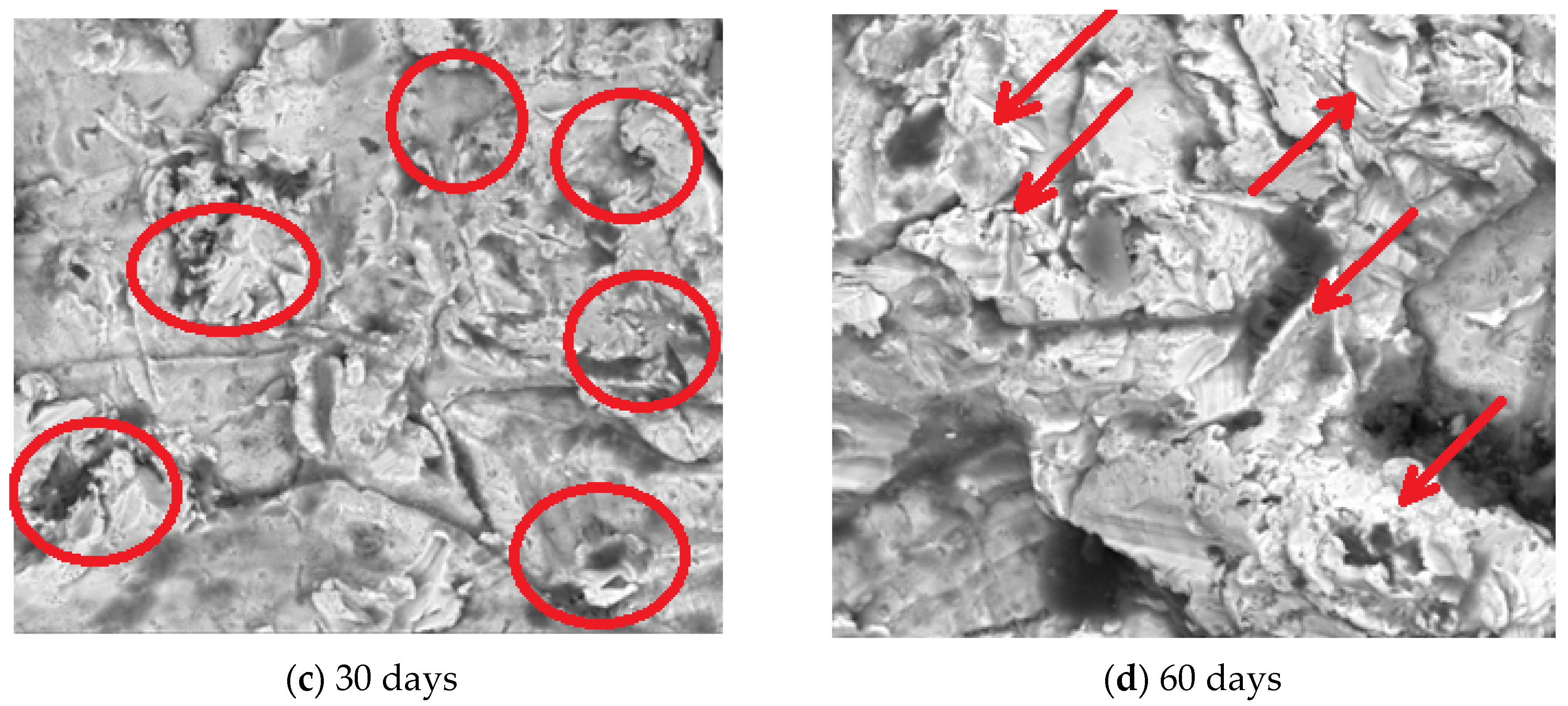
The SEM images (Figure 1) show surface corrosion of the sample as pitting in the first two weeks of exposure and, during the next two weeks, the formation of porous structures. According to [22], this porous structure may not be pitting (a type of corrosion that often appears) but porous single crystals of Cr2O3 and Co3O4. This hypothesis is strongly supported by ICP-MS that does not show any increase in metal ions into the SBF and pH and EC plots that show an increase in their values.
Thus, the proposed formation mechanisms consist of Cr and Co ions, under the influence of the acidic environment of the SBF (mainly due to HCl) forming porous single crystals of Cr2O3 and Co3O4, as has been studied by [22].
The surface analysis was performed, as in [23], and showed that, during the first two weeks of exposure, the material became porous due to the metal ion release into the SBF and, as a direct consequence, the porous surface increased almost 150% (Figure 1b). In the next two weeks, the formation of the oxide layer can be observed since most of the pores shrink almost 60% (Figure 1c). In the second month of exposure, the formation of porous single crystals of Cr2O3 and Co3O4 can be observed on the sample’s surface (Figure 1d).

3.1.2. XRD Assessment

An XRD assessment is usually used in materials science for determining the crystallographic structure of a material, and it is one of the most used techniques in the field. It uses X-rays to irradiate the material. Firstly, incident X-rays are sent towards the material and the reflected X-rays are measured in terms of intensities and angles.
In this study, X-ray diffraction (XRD) was used to establish if and/or what kind of oxides formed on the sample’s surface. As stated before, a D8 Discover diffractometer (Bruker, Billerica, MA, USA) was used for sample analysis.
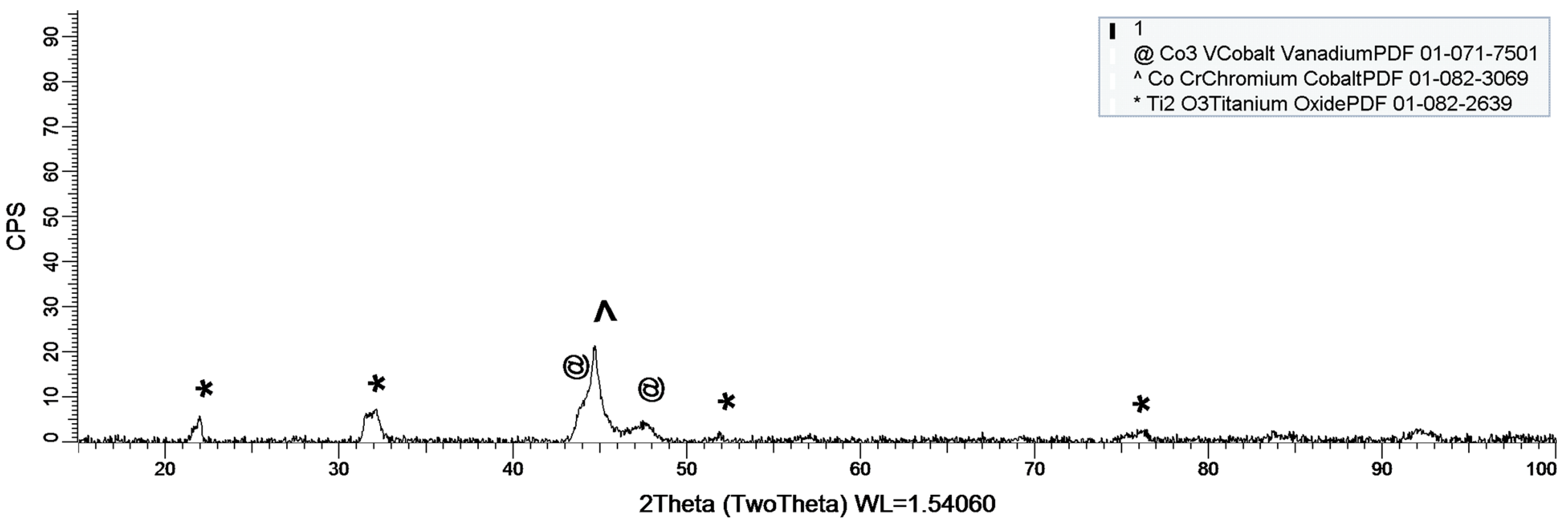
Figure 2 shows the existence of a protective layer on the polished surface during sample exposure to the SBF. On the basis of each sample’s composition, different oxide layers form on the surface.
As shown in Figure 2, the cobalt-chromium (CoCr) protective layer, which is actually an alloy, is formed on the sample’s surface. The layer does not have a crystalline structure (peak dimensions are rather modest) but it is well represented leading to the conclusion that it takes a while, but after its formation, the layer offers a protective interface between the SBF and the metallic implant.

3.1.3. Mass Variation Assessment

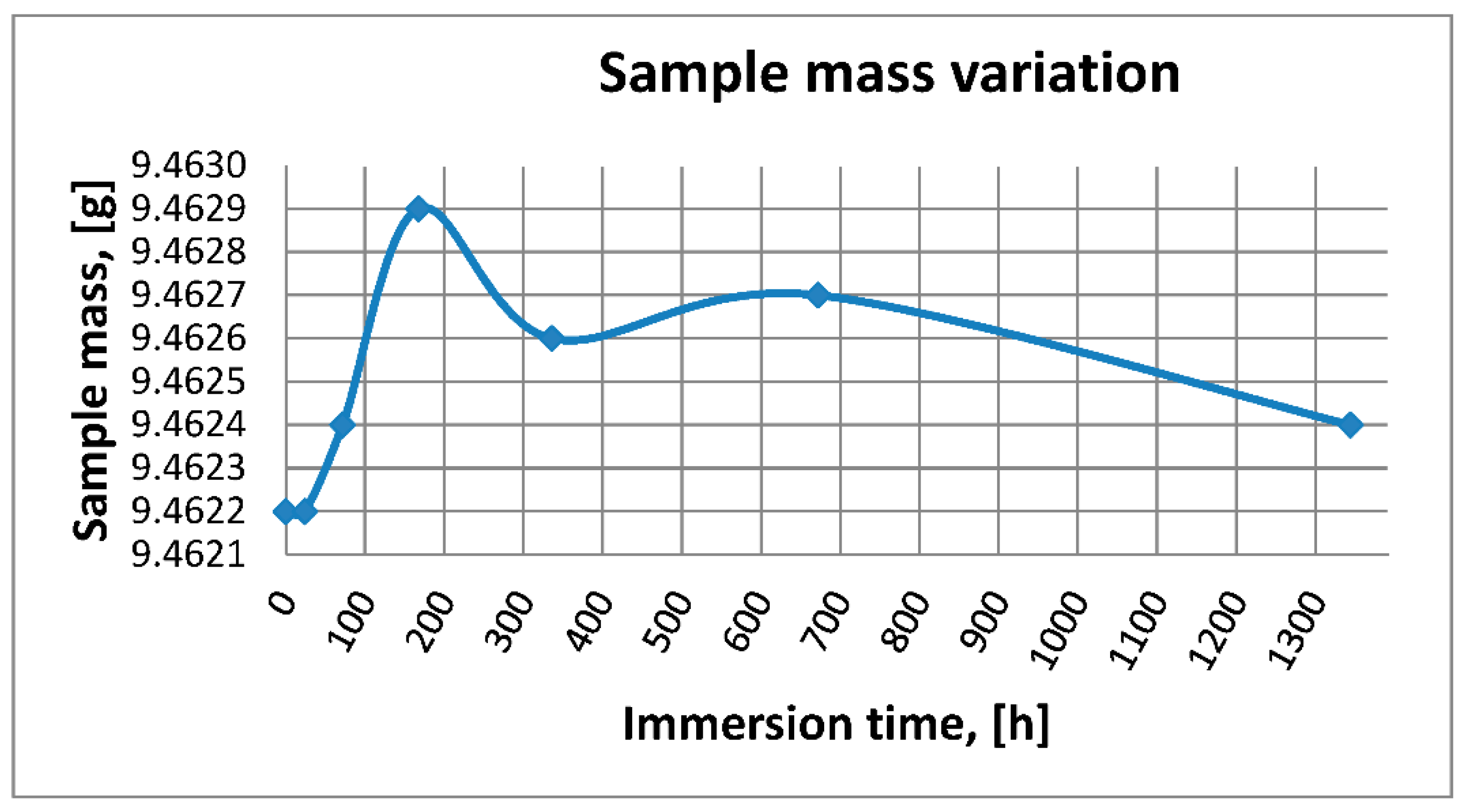
The mass variation assessment as shown in Figure 3 was conducted by a gravimetric comparison of the sample’s mass. Thus, the sample was weighed at its initial state, and then after 15, 30, and 60 days of exposure in the SBF. The aim of the assessment is to highlight the mass loss and/or gain while the sample is in the SBF. On the one hand, mass loss can be correlated with metal ion release, but this assessment is made by using ICP-MS, as described in Section 3.2.2. On the other hand, mass gain may occur due to the formation of metal oxides on the sample’s surface, as emphasized in Section 3.1.2.

3.2. SBF Characterization

3.2.1. SBF pH and Electrical Conductivity Assessment

The pH value refers to the hydrogen ion concentration in a solution. The hydrogen concentration is closely related to corrosion phenomena, since a low pH value indicates an acidic environment suitable for surface corrosion. In addition, electrical conductivity shows the ion concentration in a solution; the higher the value, the higher the number of ions that are dissociated.
Therefore, pH and electrical conductivity monitoring represent an important assessment in order to evaluate the redox phenomena that occur while the sample is immersed in the SBF.
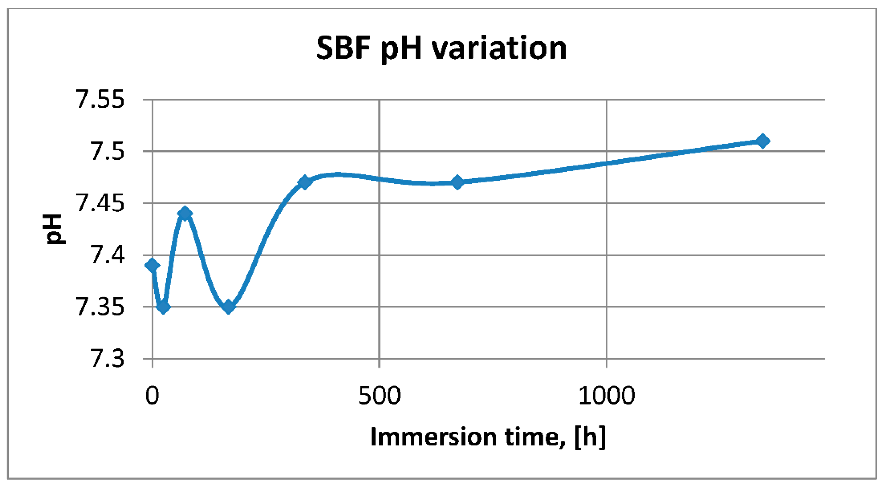
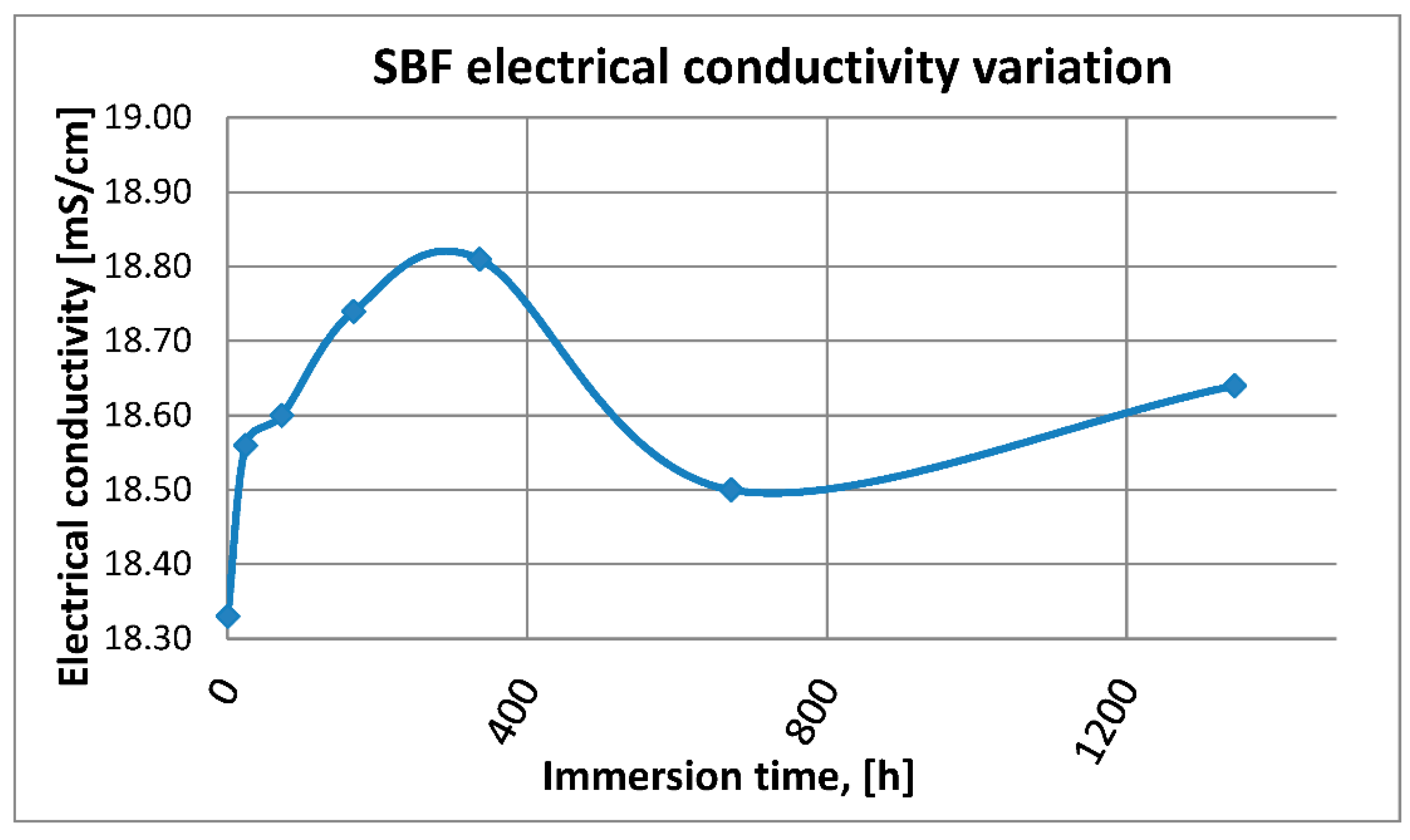
It can be observed in Figure 4 and Figure 5 that the variation of pH values and electrical conductivity are closely interdependent, as well as with mass variation shown in Figure 3. Thus, observing the curve’s allure which indicates pH and EC variation during the immersion period, in the first week of exposure, the SBF’s pH varies significantly while the electrical conductivity increases. During this period, the sample gains mass due to the formation of an oxide layer on its surface. Redox phenomena during the first week of exposure are intense, as seen in Figure 4, and the concentration of metal ions is increased, as can be observed in Table 3.
Furthermore, this trend continues during the second week of exposure when the sample’s mass decreases as metal ions are dissociated in the SBF, correlated with a continuous increase in electrical conductivity and pH.
After the second week of exposure, the amplitude of redox phenomena diminishes, as the protective layer forms on the sample’s surface.
The most probable hypothesis regarding the allure of the plots shown in Figure 3, Figure 4 and Figure 5 can be described as follows: The newly formed oxide layers of Cr2O3 and Co3O4 are still reacting to each other in order to form the protective layer of Co-Cr highlighted by the XRD plot. Thus, O2 is released back into the SBD in its ion form and quickly reacts with ionic H2 leading to a decrease in pH, observed in the last section of the plot shown in Figure 4. Nevertheless, metal ions do not dissociate since ICP-MS measurements show this aspect. In fact, Cr continues to be consumed since its concentration decreases (as shown in Table 3). The sample’s mass decreases in the final interval of the plot shown in Figure 3, since O2 is released from the initial oxide layers of Cr2O3 and Co3O4 and also due to the continuous (even at slower rate) release of Co and Mo ions into the SBF.

3.2.2. Metal Ion Release Assessment

ICP-MS is a powerful method for determining trace metal in given environments, due to its capability to measure very low concentrations of metal ions dissolved in fluids. This approach is well known, widely used by various research teams, and reported in frequently quoted scientific journals.
Basically, the ICP-MS method consist of determining the concentration of metal ions in a given solution. Thus, as required by the experimental design, 50 mL of the SBF used for sample immersion was collected and the solution was used for determining the nature and concentration of metal ions that might have dissociated from the sample into the SBF.
Given the data provided by Table 1, the following metal ions were monitored: Co, Cr, Mo, and Mn, since it is well known that large concentrations can lead to allergic and/or toxic reactions.
Table 3 shows the variation of metal ions dissociated from the sample in the SBF during the exposure period. Given the fact that the sample’s exposed surface is relatively large, being almost impossible for a metallic implant to lose such a large area of protective layer, the immediate effect is the high concentration of metal ions released into the SBF. The aim of this assessment is to highlight the formation of a new protective oxide layer soon enough after the implant’s surface is damaged (for various reasons, e.g., poor manipulation during implant surgery, mechanical shock, etc.) and to assess the concentration of metal ions dissociated into the SBF.
It can be observed that the formation of the oxide protective layer occurs after just 1 month of exposure. The correlation with pH, electrical conductivity, and mass variation plots highlights the fact that 3D-printed CoCr-based alloy may be used as orthopaedic implant. More mechanical and biocompatibility testing must be performed in the near future, but steps forward have been made.
Even though the metallic sample used in this study had a protective film on its surface, sample preparation removed it before immersing the sample in the SBF. It should be mentioned that the exposed surface was 909.65 mm2, and based on this, the corrosion rate and ion release rate could be calculated.
Table 4 shows the metal ion release rate from each sample and their corrosion rate. The values can be calculated using the following formula:
c i = m i ,   s o l m i , s a m p l e × S × 16
where ci is the ion concentration, mi,sol is the ion mass in solution, mi,sample is the ion mass in sample, S is the exposed surface and, 16 is the number of weeks of exposure.
The corrosion rate can be calculated by using the following formula:
C r = m m m i × S × 16
where mm is the measured mass of the sample, mi is the initial mass of the sample, S is the exposed surface and, 16 is the number of weeks of exposure
The corrosion rate is almost insignificant (e−5) since its measurement is grams over mm2 and week. Most implant materials are kept in the body for a maximum of 2 years (almost 100 weeks in bad cases), and the overall corrosion rate can be declared as 4.3‰. The more important aspect is the release rate of Mn, but as Table 3 shows, this release is only in the first 72 h of exposure, then, the trend is constant, and therefore it can be considered that Mn turns passive.
As a comparison, Table 5 lists the maximal allowed concentrations in the human body and the biological effects.

4. Conclusions

After being immersed for 60 days in a blood plasma SBF and having a large area depleted from its protective oxide layer, the sample shows pitting corrosion in the first two weeks of exposure which is visible by SEM.
Although the material has a large area in direct contact with SBF, a new protective layer of CoCr alloy is formed relatively quickly, as highlighted by the XRD assessment. Nevertheless, during this period, metal ions are released in the SBF and the more concerning ones are Co and Cr.
The pH, electrical conductivity, and sample mass variation give a general idea about redox phenomena that occur.
A 3D printing technique was used for producing a CoCrMo-based alloy to be used as an orthopaedic implant by using the SLM technique and the incipient conclusion is that the produced CoCrMo alloy is suitable for such applications.
The concentration of metal ions dissociated from the biomaterial into the SBF solution was assessed by using the ICP-MS technique, which highlighted that the concentration of some metal ions varied during SBF solution exposure. The main conclusion is that those ions form a protective layer on the sample’s surface mainly due to their reactivity and lead to the passivation of the exposed surface, thus, minimizing the concentration of ions that can dissociate into real body fluid.

Author Contributions

Conceptualization, R.M. and I.M.B.; methodology, R.M., L.C.C., R.E., and G.S.; software, A.P. and G.S.; validation, R.M., I.M.B., and R.E.; analysis, L.C.C., A.T.C., G.S., T.B., and E.P.; investigation, R.M., L.C.C., A.T.C., A.P., G.S., E.P., and T.B.; resources, R.M.; writing—original draft preparation R.M., R.E., and G.S.; writing—review and editing, R.M., R.E., and G.S., funding acquisition, R.M. All authors have read and agreed to the published version of the manuscript.

Funding

This research was carried out within POC-A1-A1.2.3-G-2015, ID/SMIS code P_40_422/105884, and the “TRANSCUMAT” Project, grant no. 114/09.09.2016 (subsidiary contract no. 1/D.1.5/114/24.10.2017), a project supported by the Romanian Minister of Research and Innovation.

Institutional Review Board Statement

Not applicable.

Informed Consent Statement

Not applicable.

Data Availability Statement

Data sharing not applicable.

Conflicts of Interest

The authors declare no conflict of interest. The funders had no role in the design of the study; in the collection, analyses, or interpretation of data; in the writing of the manuscript, or in the decision to publish the results.

References

  1. Baht, S.V. Biomaterials; Narosa Publishing House: New Delhi, India, 2002. [Google Scholar]
  2. Benmassauod, M.M.; Kohama, C.; Kim, T.W.B.; Kadlowec, J.A.; Foltiny, B.; Mercurio, T.; Ranganathan, S.I. Efficiency of eluted antibiotics trough 3D printed femoral implants. Biomed. Microdevices 2019, 21, 1–10. [Google Scholar]
  3. El-Hajje, A.; Kolos, E.C.; Wang, J.K.; Malekaseedi, S.; He, Z.; Wiria, F.E.; Choong, C.; Ruys, A.J. Physical and mechanical characterization of 3D-printed porous titanium for biomedical applications. J. Mater. Sci. 2014, 25, 2471–2481. [Google Scholar]
  4. Attarilar, S.; Ebrahimi, M.; Djavanroodi, F.; Fu, Y.; Wang, L.; Yang, J. 3D printing technologies in metallic implants: A thematic review of the techniques and procedures. Int. J. Bioprinting 2021, 7, 21–46. [Google Scholar] [CrossRef]
  5. ASTM Standard F2792-12a Standard Terminology for Additive Manufacturing Technologies; ASTM International: West Conshohocken, PA, USA, 2012.
  6. Sing, S.L.; An j Yeong, W.Y.; Wiria, F.E. Laser and electron-beam powder-bed additive manufacturing of metallic imlants: A review of processes, materials and design. J. Orthop. Res. 2016, 34, 369–385. [Google Scholar] [CrossRef]
  7. Hussein, M.A.; Mohammed, A.S.; Al-Aqeeli, N. Wear characteristics of metallic biomaterials: A review. Materials 2015, 8, 2749–2768. [Google Scholar] [CrossRef]
  8. Popescu, D.; Ene, R.; Popescu, A.; Cîrstoiu, M.; Sinescu, R.; Cîrstoiu, C. Total Hip Joint Replacement in Young Male Patient With Osteoporosis, Secondary To Hypogonadotropic Hypogonadism. Acta Endocrinol. 2015, 11, 109–113. [Google Scholar] [CrossRef]
  9. Prasad, K.; Bazaka, O.; Chua, M.; Rochford, M.; Fredrick, L.; Spoor, J.; Synes, R.; Tieppo, M.; Collins, C.; Cao, A.; et al. Metallic biomaterials: Current chalanges and opportunities. Materials 2017, 10, 884. [Google Scholar] [CrossRef]
  10. Gawlik, M.M.; Wiese, B.; Desharnis, V.; Ebel, T.; Willumeit-Romer, R. The effect of surface treatments on the degradation of biomedical Mg alloys—A review. Materials 2018, 11, 2561. [Google Scholar] [CrossRef] [PubMed] [Green Version]
  11. Eliaz, N. Corrosion of metallic biomaterials: A review. Materials 2019, 12, 407. [Google Scholar] [CrossRef] [Green Version]
  12. Bidhendi, H.R.A.; Pouranvari, M. Corrosion study o metallic biomaterials in simulated body fluid. Metalurjia-MJoM 2011, 17, 13–22. [Google Scholar] [CrossRef] [Green Version]
  13. Baino, F.; Yamaguchi, S. The use of simulated body fluid (SBF) for assessing material bioactivity in the context of tissue engineering: Review and chalanges. Biomimetics 2020, 5, 57. [Google Scholar] [CrossRef]
  14. Petkovic, D.S.; Mandrino, D.; Sarler, B.; Horky, J.; Ojdanic, A.; Zehetbauer, M.J.; Orlov, D. Surface analysis of biodegradable Mg-alloys after immersion in simulated body fluid. Materials 2020, 13, 1740. [Google Scholar]
  15. Diomidis, N.; Mischler, S.; More, N.S.; Manish, R. Tribo-electrochemical characterization of metallic biomaterials for total joint replacement. Acta Biomater. 2012, 8, 852–859. [Google Scholar] [CrossRef] [PubMed]
  16. Popa, M.; Demetrescu, I.; Vasilescu, E.; Drob, P.; Ionita, D.; Vasilescu, C. Corrosion Resistance of Some Thermo-mechanically Treated Titanium Bioalloys Depending on pH of Ringer Solution. Rev. Roum. Chim. 2009, 60, 241–247. [Google Scholar]
  17. Nica, M.; Cretu, B.; Ene, D.; Antoniac, I.; Gheorghita, D.; Ene, R. Failure Analysis of Retrieved Osteosynthesis Implants. Materials 2020, 13, 1201. [Google Scholar] [CrossRef] [Green Version]
  18. Wong, K.-C.; Scheinemann, P. Additive manufactured metallic implants for orthopaedic applications, Adv. In Metallic Biomaterials. Sci. China Mater. 2018, 61, 440–454. [Google Scholar] [CrossRef] [Green Version]
  19. Available online: https://www.mee-inc.com/hamm/scanning-electron-microscopy-sem/ (accessed on 22 January 2021).
  20. Marques, M.R.C.; Loedberg, R.; Almukainzi, M. Simulated biological fluids with possible applicaation in dissolution testing. Technologies 2011, 18, 15–26. [Google Scholar]
  21. Mirea, R.; Ceatra, L.; Cucuruz, A.T.; Ene, R.; Popescu, E.; Biris, I.; Cretu, M. Advanced experimental investigation of used metallic biomaterials. Rom. J. Mater. 2019, 59, 138–145. [Google Scholar]
  22. Dickinson, C.; Zhou, W.; Hodgkins, R.P.; Shi, Y.; Zhao, D.; He, H. Formation mechanism of porous single-crystal Cr2O3 and Co3O4 templated by mesoporous silica. Chem, Matter. 2006, 18, 3088–3095. [Google Scholar] [CrossRef]
  23. Gorji, N.E.; O’Connor, R.; Brabazon, D. XPS, XRD and SEM characterization of the virgin and recycled powders for 3D printing applications. IOP Conf. Ser. Mater. Sci. Eng. 2019, 591, 012016. [Google Scholar] [CrossRef] [Green Version]
  24. Aksakal, B.; Yildirim, Ö.S.; Gul, H. Metallurgical failure analysis of various implant materials used in orthopedic applications. J. Fail. Anal. Prev. 2004, 4, 17–23. [Google Scholar] [CrossRef]
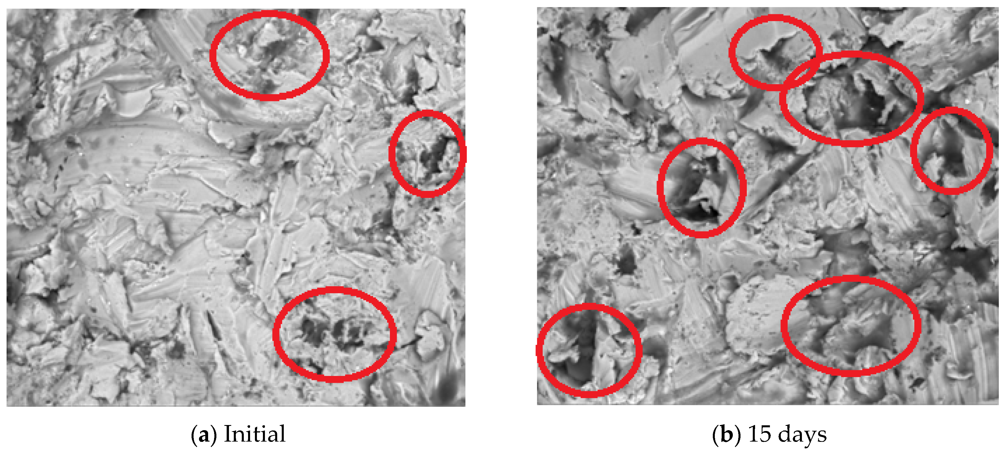
Figure 1. SEM images showing surface corrosion of 3D-printed CoCrMo metallic implant during SBF exposure. (a) Initial (0 h); (b) after 15 days; (c) after 30 days; (d) after 60 days.
Metals 11 00857 g001aMetals 11 00857 g001b
Figure 2. XRD plot for the 3D-printed CoCrMo metallic implant.
Metals 11 00857 g002
Figure 3. 3D-printed CoCrMo metallic implants mass vs. immersion time variation.
Metals 11 00857 g003
Figure 4. SBF pH vs. immersion time variation.
Metals 11 00857 g004
Figure 5. SBF electrical conductivity vs. immersion time variation.
Metals 11 00857 g005
Table 1. Chemical composition of the metallic powder.
ElementCoCrWMoOther: C, Fe, Mn, N, Si
wt.%59259.53.5Less than 1.5
Table 2. Reagents for preparing the updated simulated body fluid [20]. (reprinted from ref. [20] with permission from Elsevier).
ReagentAmount for 1 L of SBF
Sodium chloride8.035 g
Sodium bicarbonate0.355 g
Potassium chloride0.225 g
Potassium phosphate dibasic tri-hydrate0.231 g
Magnesium chloride hexahydrate0.311 g
1M hydrochloric acid39 mL
Calcium chloride0.292 g
Sodium sulphate0.072 g
Tris(hydroxyl-methyl) amino methane6.118 g
Table 3. Measured metal ion concentrations in the SBF.
ElementCo (µg/L)Cr (µg/L)Mo (µg/L)Mn (µg/L)
Time
0 h—Initial0000
24 h5.3467.390.4531.374
72 h9.7716.8520.7291.824
168 h14.6466.8011.1082.147
336 h20.326.581.6112.295
672 h30.0586.482.4132.551
1334 h30.3255.1492.5982.145
Table 4. Calculated corrosion and ion release rates.
SampleCorrosion Rate
{g/(mm2 Week)}
Ion Release
({mg/L}/(mm2 Week))
CoCrMoMnW
3D-printed CoCrMo6.87 e−51.4 e−55.13 e−51.5 e−514.9 e−510.3 e−5
Table 5. Biological effects and maximal concentrations of metal ion accumulation in the human body.
MetalEffect
Nickel (Ni)It is the main cause of contact dermatitis. The main biological parameter is the amount of metal released on the skin during direct contact and exposure to human sweat.
The limit is 0.5 mg/cm2 x week, of which an insignificant part of Ni sensitive subjects will react.
It has a toxic effect by creating cellular lesions and large cellular cultures. It is dangerous for bones and tissues, although less dangerous than Co or V, and it has cancer potency. The normal level of Ni in the blood is 5 mg/L [1].
Cobalt (Co)Its function limits the role of vitamin B12 [1], by diminishing the adsorption of Fe in the blood stream [24]. The normal concentration of Co in human fluids is 1.5 mg/L.
Chromium (Cr)It causes ulceration and central nerve system disorders [24]. The maximal concentration in the blood stream should be 28 mg/L. Its compounds are adsorbed only after oral ingestion. Cr (III) is usually deposited in reticular systems in the cell, while Cr (IV) can penetrate cellular membrane in both directions [1].
Aluminium (Al)It provokes epileptic episodes and Alzheimer’s disease [24]. The maximal concentration in the blood stream should be 30 mg/L.
Vanadium (V)It is very toxic in its elementary state [24], therefore, the maximum concentration should not exceed 0.5 µg/L.
Molybdenum (Mo)It is an essential element use by specific enzymes. It is easily adsorbed through the intestines, and its normal concentration in the blood stream should be 1–3 ppm. It is very toxic and sometimes lethal in large doses, regular symptoms are diarrhoea, coma, heart failure, and inhibitor for some essential enzymes. In addition, large concentration of Mo can interfere with Ca and P metabolism [1].
Publisher’s Note: MDPI stays neutral with regard to jurisdictional claims in published maps and institutional affiliations.