Article

Copper-Tantalum Metal Matrix Composites Consolidated from Powder Blends by Severe Plastic Deformation

by
Zachary S. Levin
1,2,*,
Michael J. Demkowicz
2 and
Karl T. Hartwig
2,3
1
MST-16, Los Alamos National Laboratory, Los Alamos, NM 87545, USA
2
Department of Materials Science and Engineering, Texas A&M University, College Station, TX 77840, USA
3
Shear Form, Inc., Bryan, TX 77801, USA
*
Author to whom correspondence should be addressed.
Metals 2021, 11(7), 1010; https://doi.org/10.3390/met11071010
Submission received: 27 April 2021 / Revised: 4 June 2021 / Accepted: 17 June 2021 / Published: 24 June 2021

Abstract

:
We investigated the effectiveness of severe plastic deformation by equal channel angular extrusion (ECAE) for consolidation of metal powders into metal matrix composites. Equal volumes of copper (Cu) and tantalum (Ta) powders were consolidated at ambient temperature via different ECAE routes. Composites processed by ECAE routes 4E and 4Bc were also processed at 300 °C. The resulting materials were characterized by scanning electron microscopy (SEM) and compression testing. Processing by route 4Bc at 300 °C resulted in the highest compressive strength, lowest anisotropy, and least strain rate sensitivity. We conclude that the superior properties achieved by this route arise from mechanical bonding due to interlocking Cu and Ta phases as well as enhanced metallurgical bonds from contact of pristine metal surfaces when the material is sheared along orthogonal planes.

1. Introduction

1.1. Metal Matrix Composites

Our goal is to examine the prospects for using equal channel angular extrusion (ECAE) to consolidate powders at low temperature (i.e., without sintering) into metal matrix composites (MMCs) with controlled microstructure. MMCs, also referred to as pseudo-alloys, are a class of materials that have a composite structure with a metal matrix. The matrix phase can either be an alloy [1] or single element [2], while the filler phase can be metal [3,4], intermetallic [5,6], or ceramic [7,8]. Like all composites, MMCs have the potential for unique combinations of properties that can exceed those of their constituent components. Multiple variables influence the properties of MMCs, including composition [9,10], microstructure [11], and processing history [12,13,14,15,16,17,18]. For example, tungsten heavy alloys combine the high density, strength, and thermal stability of tungsten while enhancing ductility through the incorporation of an iron or nickel alloy matrix [19,20].
MMC fabrication usually involves powder consolidation and may be broadly divided into liquid or solid-state processing [21]. Liquid processing includes dispersion of fillers in a liquid matrix phase, infiltration of fiber networks with molten metal, or thermal spray processing. This approach can be used to produce large parts with methods similar to traditional casting and forming. However, it is limited to low melting temperature alloys. Moreover, maintaining uniform composition can be challenging. Finally, constituent reactions, grain coarsening, and oxidation can degrade mechanical properties [22].
Solid state processing, including powder metallurgy (PM) methods, can also be used to produce MMC [23]. This approach can impart greater property uniformity due to better control over powder mixtures prior to fabrication. This approach may be used on materials with very high melting points. Nevertheless, while sintering temperatures are lower than melting, the metal phases still coarsen, limiting grain size strengthening, and phase changes may occur as temperatures vary during processing.
The other solid-state fabrication techniques for MMCs rely on diffusion bonding produced by intimate contact between metal surfaces subjected to severe plastic deformation (SPD) combined sometimes with elevated temperature during processing or after SPD. Techniques that use this approach include wire drawing and restacking [24], accumulative roll bonding (ARB) [25,26], and ECAE [27,28,29,30]. Through intensive shear, these processes are able to consolidate and bond metal constituents and are effective at minimizing porosity, sometimes reaching near theoretical density. Of these techniques, ECAE is the only one that can produce a nearly isotropic distribution of the matrix and filler phases. ECAE can also produce bulk material that can either be worked further or directly machined into parts. At the same time, ECAE enables greater control over microstructure, texture, and morphology than pressing and sintering alone.
Cu and Ta have near complete immiscibility below 1084 °C and do not form any intermetallic compounds [31,32]. Cu is face centered-cubic (FCC) while Ta is body centered-cubic (BCC). Other researchers have investigated the fabrication of Cu-Ta alloys by ECAE [33,34]. In these earlier investigations, the Cu and Ta powders we pre-mixed and mechanically ball milled prior to consolidation by ECAE, resulting in a nearly pure FCC Cu with dispersed BCC Ta nanoclusters [35]. The Ta nanoclusters significantly improved the mechanical behavior and thermal stability without significantly impacting other properties like conductivity [36]. The retention of distinct FCC Cu and BCC Ta phases in these systems after severe deformation processing, first during milling then by ECAE, provides the opportunity to examine mechanical response in this multi-phase system composed of distinct, unalloyed metal phases.
While these previous works have focused on Ta nanocluster-reinforced Cu, in the current work we have investigated the consolidation of blended Cu and Ta powders of equal volume. Our motivation is to develop a new material that will be used for further computation and modeling studies involving the impact of phase interface conditions, phase crystal structure differences, and density differences on quasi-static and intermediate strain rate mechanical behavior. Our investigation proceeded in two steps. First, a number of routes were selected for processing at ambient temperature in order to examine the impact of total strain and deformation path on morphology and the effectiveness of consolidation. In the second stage, a candidate was selected for further processing at elevated temperature. The effectiveness of consolidation was evaluated through compression testing and the microstructure characterized by electron microscopy.

1.2. ECAE

The ECAE process involves extruding a billet—typically with square or circular cross section—through a confined channel with a sharp change in direction between the inlet and exit. Common angles for this direction shift are 90° and 120°, however any angle between 90° and 180° may be used. As the work piece is forced through the intersecting channels, the material undergoes simple shear, imparting a significant amount of strain. For a 90°—intersecting angle, the resulting shear strain is approximately 1.16, which is roughly equivalent to a 69% area reduction in conventional extrusion. A detailed review on ECAE may be found in Segal’s work [37,38].
Unlike rolling, drawing, or swaging, ECAE may be used to produce a variety of microstructure morphologies and textures by varying the ECAE processing route, i.e., the types and sequence of billet rotations between extrusions. The microstructures that can be produced fall into three categories: lamellar, filamentary, and equiaxed. Repeated extrusions without billet rotation continuously elongate the microstructures along one plane producing lamellar structures [39]. Rotation of the billet by alternating +90° and −90° rotations between extrusion passes deforms the microstructure along both the longitudinal and flow planes, elongating structures on two axes producing a fibrous structure, and is referred to as route B [16].
Finally, by rotating the billet so that an initial volume element is restored produces an equiaxed microstructure. Three different routes yield this outcome: C, E, and Bc. Route C is the simplest of these and is accomplished by rotating the billet 180° between extrusions. Route E builds on route C, by combining two route C extrusions with a 90° rotation between them. For route Bc, the billet is rotated +90° between each extrusion, and after 4 extrusions the volume element is restored. For this reason, it is uncommon to see routes with the Bc suffix without a multiple of 4 in front of them, e.g., 4Bc or 8Bc. The ability to control microstructure combined with the large strain space accessible and bulk work-piece dimensions make ECAE an ideal tool for studying the impact of microstructure morphology on the mechanical behavior of MMCs.

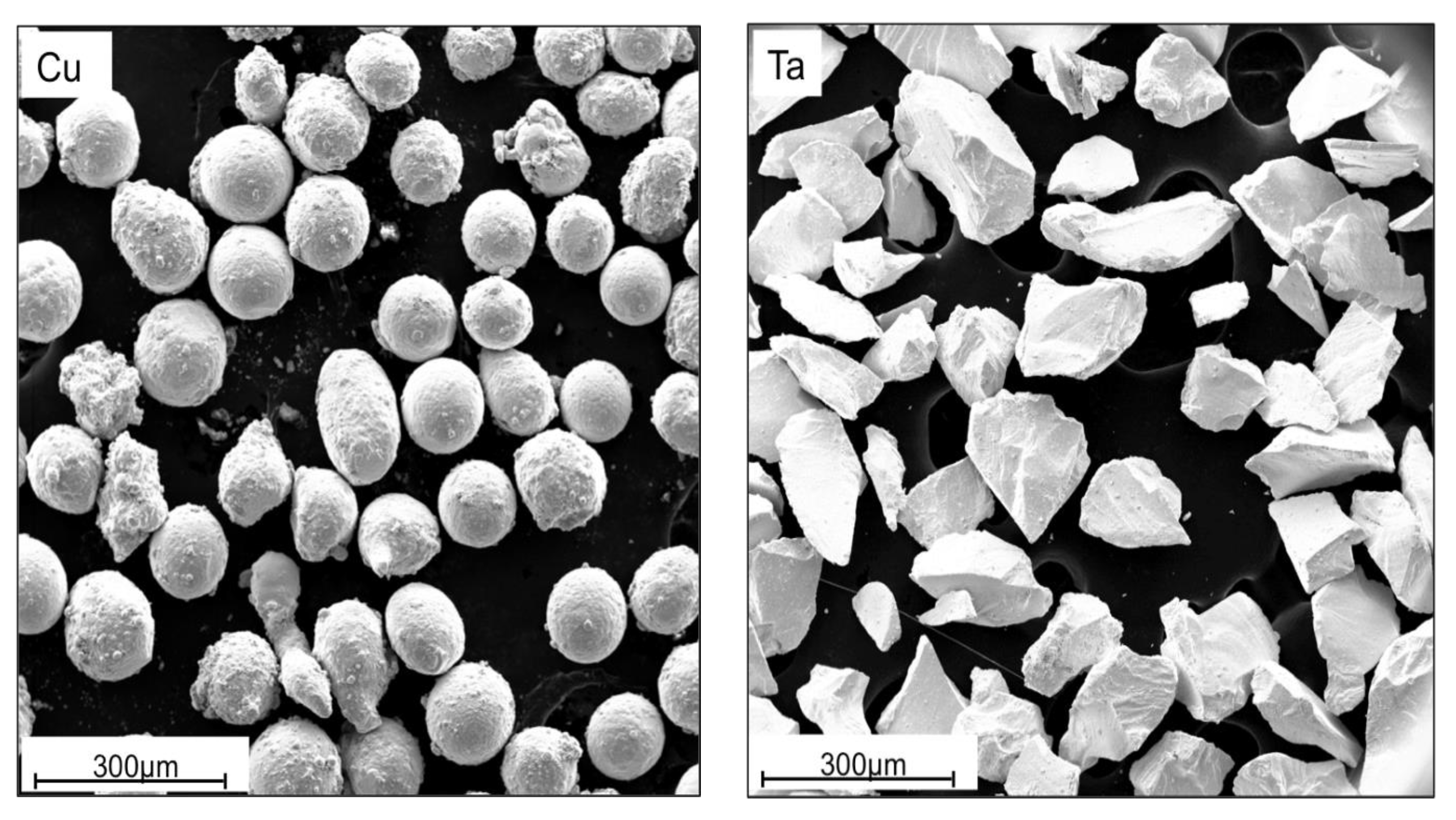
2. Materials and Methods

We have examined the impact of processing route, total strain, and processing temperature on the mechanical behavior of copper (Cu)-tantalum (Ta) blended powder composites. Cu and Ta do not form compounds and have minimal solubility over their entire composition up to the solidus. Their differing crystal structures (Cu is FCC while Ta is BCC) and densities (8.96 g/cm3 for Cu and 16.65 g/cm3 for Ta) make them interesting model materials for high strain rate mechanical testing, in particular to study the influence of heterophase interfaces and large elastic impedance mismatch.
The consolidation process is optimized by initially conducting extrusions at ambient temperatures following a variety of routes followed by characterization of the microstructure and mechanical behavior of the consolidated material. Promising routes were selected for processing at 300 °C. Materials consolidated at these elevated temperatures were then mechanically tested in multiple orientations and at different strain rates in order to determine the effectiveness of the processing.
The Cu and Ta powders used in this investigation are pictured in Figure 1. Their size and aspect ratio were found by analyzing scanning electron microscopy (SEM) images with the Fiji ImageJ software [40].
The Cu powder was sourced from Alfa Aesar (Haverhill, MA, USA). It is spherical with an average diameter of 126 μm ± 15 μm and an aspect ratio of 1.2 ± 0.2. Ta powder was provided by H.C. Stark (Goslar, DEU) and is HRC grade capacitor powder. The particles possess an average diameter of 153 μm ± 47 μm and aspect ratio of 1.8 ± 0.6. Cans used for extrusion were made of 304 stainless steel. Each can was approximately 178 mm long, with a cross section of 25 mm × 25 mm and included a circular center cavity 140 mm long with diameter 12.5 mm. Plugs for the cans where 38 mm long and 12.5 mm in diameter and also made of 304 stainless steel. Powder handling was done in a glove box under an argon atmosphere.
Powders were combined in a 1:1 ratio by volume, equivalent to a mass ratio of 1:1.86. The powder mixture was then sealed inside a plastic wide-mouth Nalgene bottle. The Nalgene bottle was removed from the glove box and agitated inside a Turbula T2F Powder Mixer Shaker (WAB US Corp., Allendale, NJ, USA) for 20 min. Mixed powders were added to the cans inside the glove box and a metal plug inserted and sealed with black electrical tape. Prior to extrusion, cans were pre-compacted and sealed with a manually operated hydraulic press in order to minimize oxidation. Graphite sheet was wrapped around the cans to reduce friction during ECAE.
The cans were extruded using a 25.4 mm2 square cross section, sliding wall, zero degree fan angle ECAE tool at approximately 10 mm/s. For processing at elevated temperatures, the ECAE tool was pre-heated to the desired temperature. Billets were placed into the tool pre-upset to ensure good contact with the channel walls and to maintain the seal between the plug and can wall. They were allowed to reach thermal equilibrium with the tool for 30 min before extrusion.
Mechanical properties were obtained through uniaxial compression testing at a quasi-static strain rate of 10−3/s. Samples were prepared by sectioning with a silicon carbide cutting saw and mechanically polished down to 800—grit using silicon carbide polishing pads. The samples processed at ambient temperature measured 3 × 3 × 6 mm3 while those processed at elevated temperature measured 4 × 4 × 8 mm3. The length-to-width ratios of these samples are small enough to ensure that buckling is not a concern for these compression tests. The load frame used during testing has high compliance. Therefore, our stress-strain curves do not permit the reliable determination of elastic moduli.
During testing, samples were placed between tungsten carbide platens affixed to the load frame. Graphite sheet was used as a lubricant between the sample and the platens. Strain was measured at the tungsten carbide platens by an MTS model 632.53E-14 extensometer (MTS, Eden Prairie, MN, USA) with a gauge length of 12.7 mm. The platen/graphite sheet/sample/graphite sheet/platen stack nevertheless appears to have significant compliance (as evidenced in the different loading/unloading moduli shown in Supplementary Table S1), so we do not believe our stress-strain curves permit reliable determination of elastic moduli. Material processed at elevated temperature was tested along the three primary extrusion orientations: longitudinal, extrusion, and flow directions. Two additional strain rates—10−2/s and 10−1/s—were investigated for the high temperature material along the extrusion direction. Material quantity limitations permitted a limited number of these additional tests. Compression testing was halted when either the load frame reached its safe limit, the load on the samples dropped, or deflection of the sample reached a critical state which might harm the test frame or extensometer.
Material microstructure was characterized using optical microscopy and SEM. Samples were hand polished with silicon carbide pads to 800 grit followed by polishing on a felt pad with colloidal silica and finished on a vibratory polisher with colloidal silica.

3. Results

3.1. Room Temperature Processing

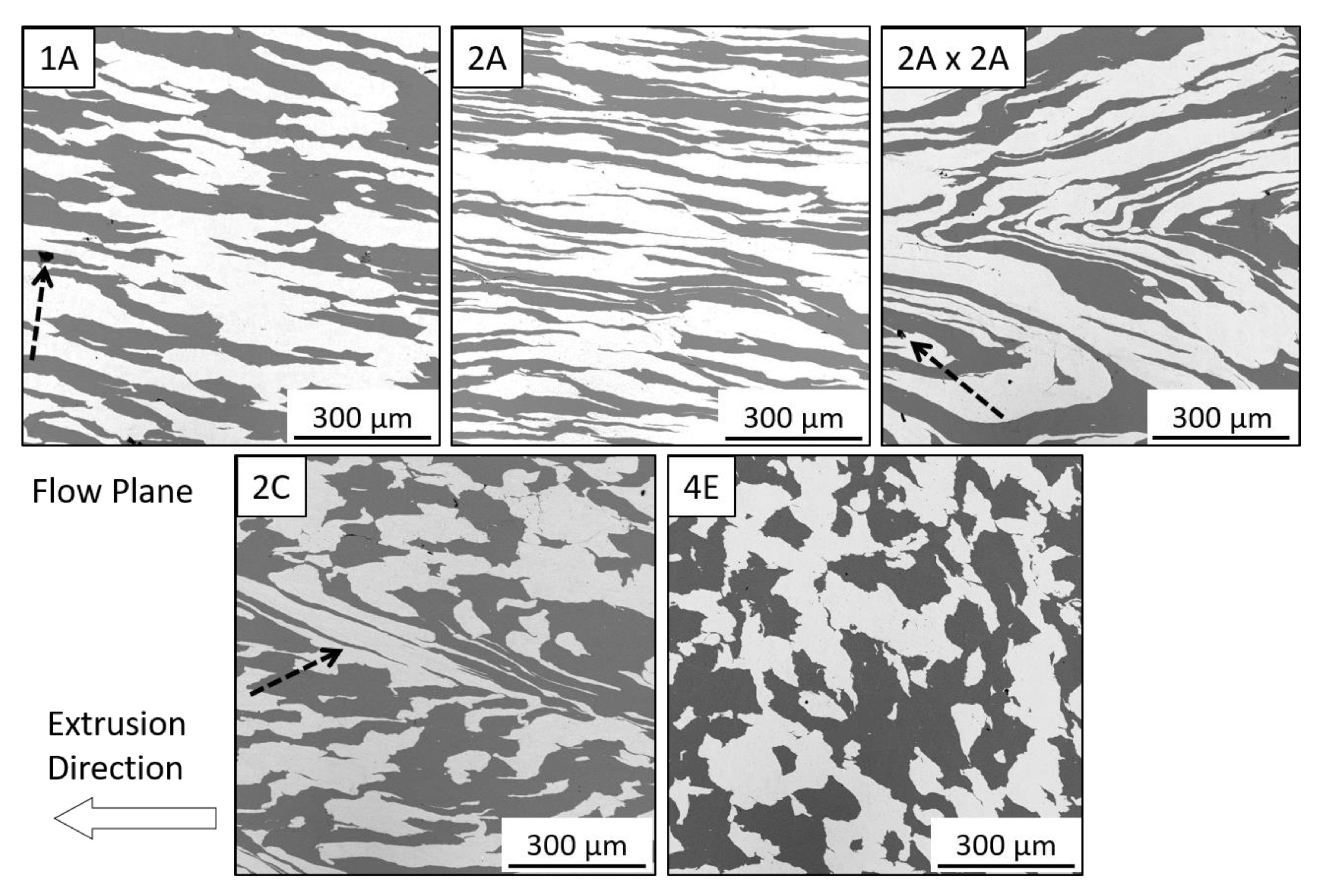
3.1.1. Microstructure

The scanning electron micrographs in Figure 2 show materials processed by routes 1A, 2A, 2A × 2A, 2C and 4E at ambient temperature. Ta is the brighter phase. Images are taken along the flow plane of extrusion; the arrow indicates the extrusion direction. Visual inspection suggests that the constituents are well-consolidated, with intimate contact between the Cu and Ta phases and no apparent porosity. Route 1A (top left) produced an elongated microstructure, as anticipated. A small pore can be seen in the copper phase at the interface of the Ta phase which is indicated by an arrow. In the 2A material (top middle), the substantial increase in elongation over the 1A is clearly evident. This outcome is to be expected, as the degree of elongation compounds with each route A type extrusion.
Route 2A×2A is an experimental extrusion route where, after two route A extrusions, the billet was rotated 180° and extruded two more times by route A, thereby returning the deformed volume element to its original shape. This was done with the intent of producing the maximum amount of diffusion bonding between the Cu and Ta phases by maximizing their contact area while still arriving at an equiaxed microstructure at the end of processing. However, the intended effect was not achieved. As can be seen from the micrograph labeled 2A×2A (top right), the material components folded, instead of returning to their original shapes. This folding may have begun by shear localization or kinking of the layered morphology in 2A. A pore is noted by an arrow in this material.
Deformation caused by shear localization may be seen in the micrograph of the sample processed by route 2C (bottom left), and indicated by arrows, where the Ta layer has been drawn out at an angle from the extrusion direction. Route 4E (bottom right), which involves a 2C extrusion followed by a 90° rotation and then another 2C extrusion, has the most equiaxed structure. The same type of shear localization that occurred in the 2C sample is not observed in the 4E material. This is unexpected as both entail the same 2C processing steps. However, as Figure 2 only shows a limited sample area, we cannot exclude the possibility of folded phase morphologies in other parts of the 4E sample.
A summary of the results obtained from the ambient temperature extruded samples is shown in Table 1, which includes the accumulated strain, the Vickers hardness measured with a 300 g load, the area fraction of the Cu phase, and the Cu-Ta interface trace length per unit area of the section. The values following the plus/minus (±) sign are the standard deviations of the measured value. Vickers hardness values increase with the amount of strain, consistent with an increase in dislocation density and refinement of grains. These processes typically occur in cold worked material and have been observed in both pure Cu [41] and Ta [29] processed by ECAE.
The area fraction of Cu area nominally ought to be 50% in all samples, since all were prepared from 50% Cu powder, by volume. Deviations from this expected value may be attributed to a several possible sources. Powders may have segregated somewhat while samples were prepared, transferred, or extruded creating a non-uniform distribution of the Cu and Ta. ECAE processing may have induced an anisotropic phase distribution, resulting in an observed area fraction that depends on sectioning plane. This conclusion is consistent with the 4E sample, which has the most equiaxed microstructure but a Cu area greater than 50%. The interface trace length per unit area was determined using the ImageJ software. The substantial differences in this quantity from sample to sample are due to the differing aspect ratios of the constituent phases.

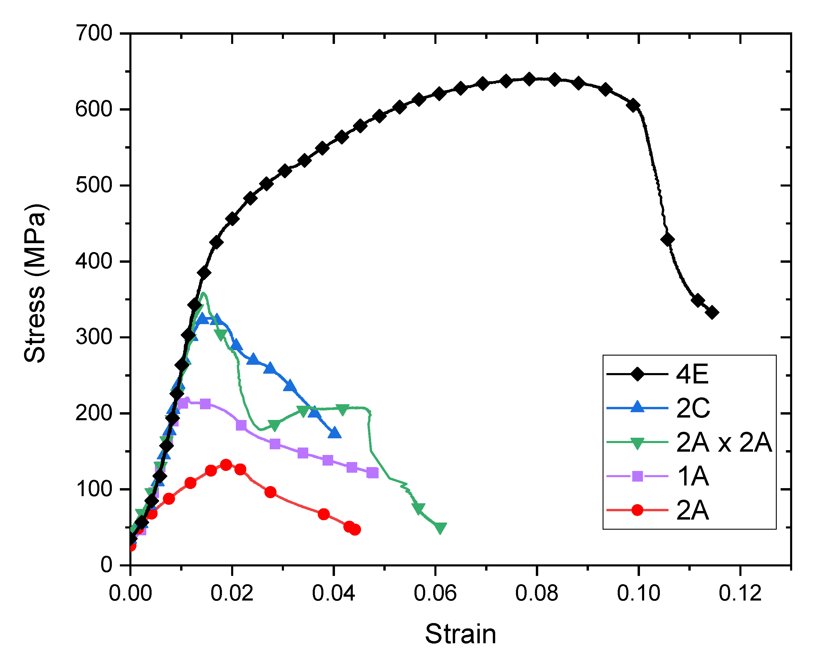
3.1.2. Mechanical Behavior

The mechanical response of the room temperature processed composites was evaluated by quasi-static (10−3/s) compression testing. Characteristic experimental stress-strain curves for each test condition are shown in Figure 3. The curves presented are representative of the individual cases and were selected to illustrate the differences in mechanical behavior of each processing condition. Two sets of compression tests were conducted; the first was under monotonic loading, displayed in Figure 3, and the second with periodic unloads. For most samples, 1A, 2A, 2A×2A and 2C, a pronounced load drop occurred before unloading could be applied, or shortly thereafter.
Most of the samples exhibited a sharp decline in load near the elastic limit. During testing, samples did not barrel but instead tended to shear, resulting in a lateral deflection of the top and bottom surfaces of the compression sample, which in turn put lateral stress on the load frame. When this occurred, testing was halted in order to minimize any risk of damaging the load frame. Samples did not fracture in these tests. Rather, they appeared to shear, sometimes fissures appeared, but the samples always remained intact such that no fracture surfaces were available for inspection. The material processed by route 4E deformed well beyond the elastic limit and work-hardened prior to exhibiting a load drop. We conclude that this processing route was the most successful at producing a well-bonded composite. All associated stress-strain curves pertaining to this work are included in the Supplementary Information.
The 2A×2A and 2C materials have similar strains and stresses beyond the elastic limit. This finding is unexpected as the 2A×2A material has twice the working of the 2C material. Moreover, while both of these materials were initially expected to have similar phase morphology, Figure 2 shows that they do not. Their comparable behavior may be the outcome of similar pre-existing flaw distributions. Processing by route 2A appears to be the least successful at consolidation, as evidenced by this material’s early deviation from elastic behavior and low ultimate stress and strain.

3.2. 300 °C Processing

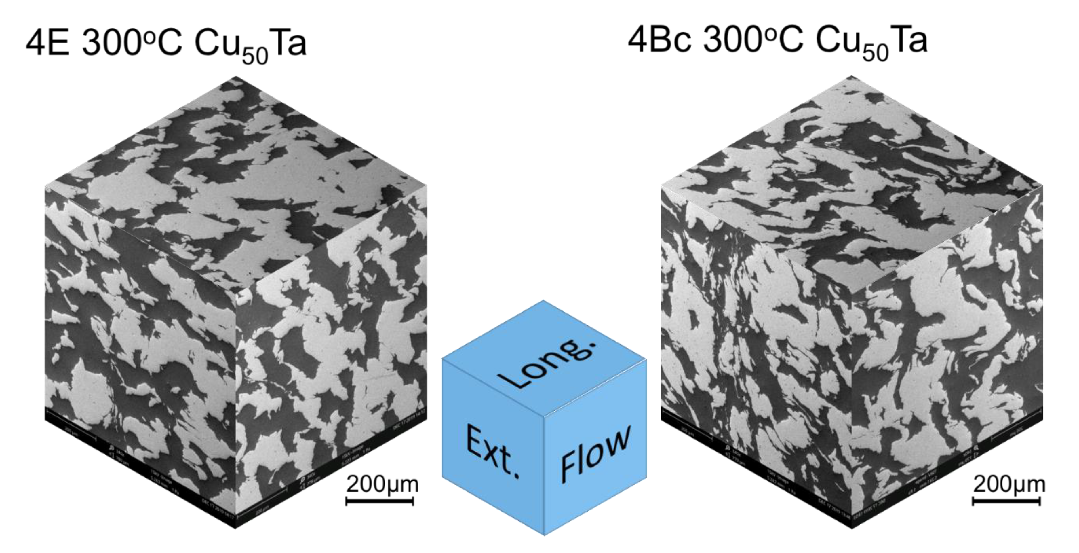
3.2.1. Microstructure

Based on the initial stress-strain data, route 4E was selected for further investigation in elevated temperature (300 °C) consolidation. We also conducted elevated temperature processing by route 4Bc as it gives rise to similar volume element deformation as route 4E: both routes produce an equiaxed final microstructure as the initial volume element is restored. The difference between these routes is related to the order of billet rotation between extrusion passes. In route 4E the volume element is returned to its initial condition in the second and fourth passes with a 90° rotation between the second and third, while in route 4Bc the volume element is only restored upon the fourth extrusion. Thus, route 4Bc is expected to impose greater elongation of the particles between the first and second extrusions, increasing the amount of particle-particle bonding.
Composite images of microstructures along the flow, longitudinal, and extrusion planes for both processing routes are shown in Figure 4. Cu is the darker phase. Table 2 summarizes the Cu area fraction as well as the interface trace length per unit area for both samples. The marked differences in Cu area fraction on the different sectioning planes suggest that the anisotropy of the composite structure is the likely cause of variations in these quantities reported in Table 1 for the samples processed at ambient temperature. The difference in interface trace length for 4Bc indicates a greater Cu-Ta interface area and improved bonding between phases.

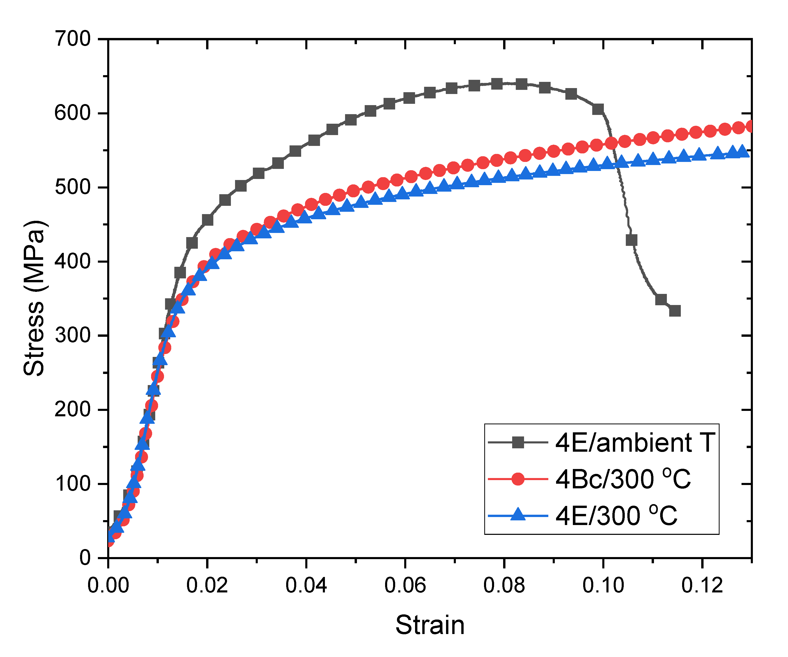
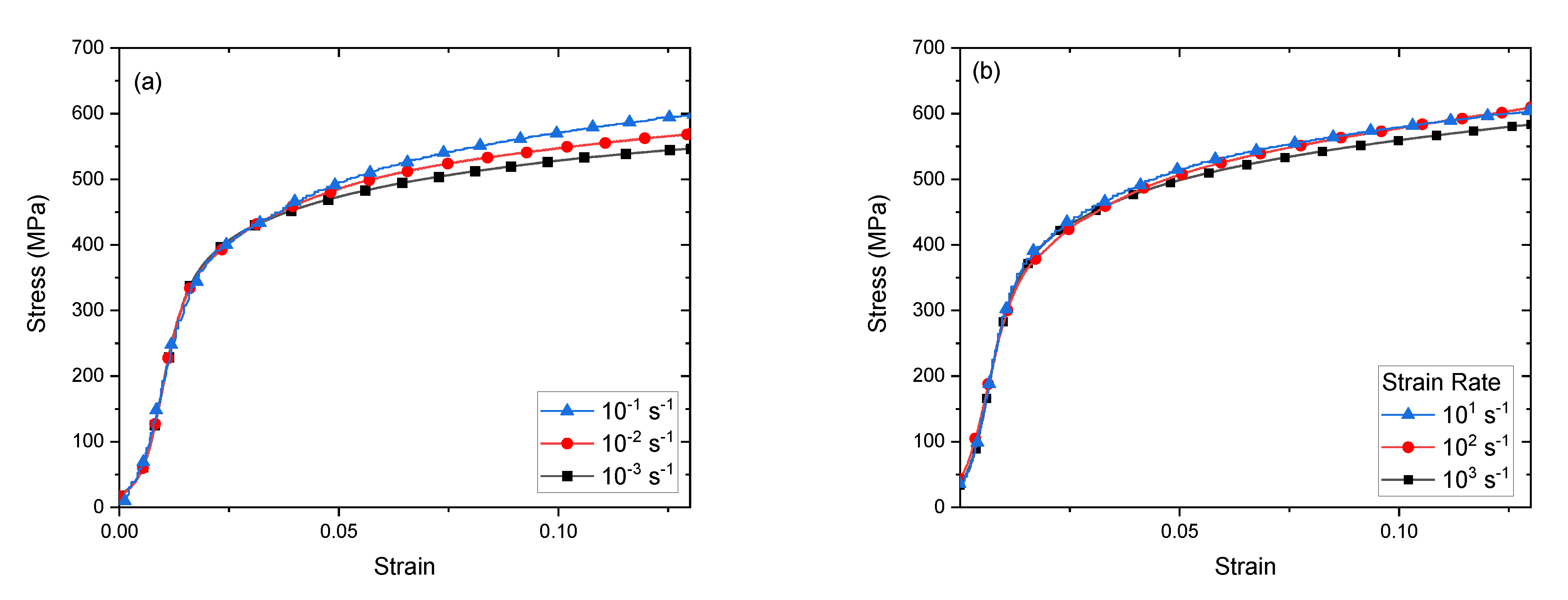
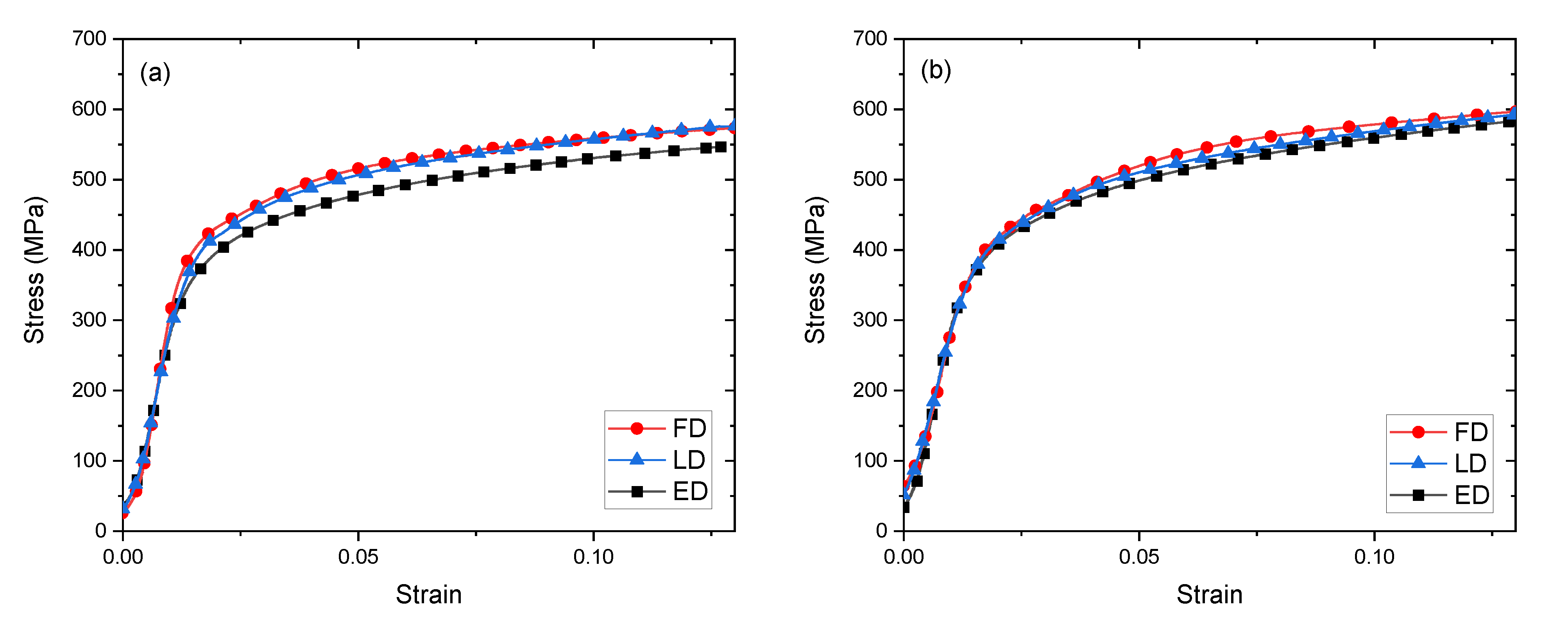
3.2.2. Mechanical Behavior

Compression stress-strain curves for route 4E and 4Bc materials processed at 300 °C are shown in Figure 5. For comparison, the stress-strain curve for route 4E consolidation at ambient temperature is also shown. Both 300 °C materials exhibit comparable mechanical response. They are more ductile than the ambient temperature processed material, as neither exhibited a load drop in the test range. Their yield stresses are nearly the same. However, the 4Bc material appears to undergo more strain hardening than the 4E material. By contrast, the ambient temperature processed material is approximately 20% stronger than both samples processed at 300 °C. This difference may be due to greater recovery of dislocation densities in the Cu phase of the composites processed at elevated temperature.
Mechanical anisotropy in the 300 °C-processed materials was investigated by conducting quasistatic (10−3/s) compression tests in the three orthogonal ECAE directions: longitudinal (LD), extrusion (ED) and flow (FD), as shown in Figure 4. Stress-strain curves for the 4E and 4Bc 300 °C tests are shown in Figure 6a,b. Both materials are plastically isotropic, to a good approximation. The largest deviation in isotropy occurs for deformation of the route 4E material along the extrusion direction (ED). The greater anisotropy in 4Bc material may be due to the increase in phase interface area noted in Table 2. This greater interface area likely results in improved bonding, and a more homogenous mechanical response and may also increase strength.
To assess strain rate sensitivity, the 300 °C -processed composites were further tested under two additional strain rates along the extrusion direction (ED): 10−2/s and 10−1/s. Corresponding stress-strain curves are shown in Figure 7. A summary of the results for all testing directions and strain rates is shown in Table 3. The strain rate sensitivity exponent m was calculated by determining the slope of the log-log plot of strain rate vs. stress at stains at 5% and 10%. For the 4E material the strain rate sensitivity exponent m is 0.0115 ± 0.01 at 5%, and 0.016 ± 0.001 at 10% strain, while for the 4Bc material, m is 0.0121 ± 0.012 at 5% and 0.012 ± 0.006 at 10% strain.

4. Discussion and Conclusions

We have shown that ECAE processing may be used to consolidate Cu-Ta metal matrix composites from blended powders. ECAE routes that deform the material on multiple planes, such as routes 4E and 4Bc, are most effective for bonding the constituent phases. Elevating the processing temperature from ambient to 300 °C produces a more malleable composite with reduced strength. Increasing the surface area between the Cu and Ta phases appears to increase yield strength while reducing plastic anisotropy and strain rate sensitivity.
Based on our findings, we conclude that the morphology of the composite constituent phases has a significant impact on consolidation and mechanical behavior of the final product. The trace length per phase area indicates strong mechanical interlocking of the Cu-Ta interface. The amount of interlocking appears to be impacted not only by the total strain but also its path during deformation, as is the case when comparing material processing at ambient temperature. The 4E, material being deformed along two separate planes due to the 90° rotations between extrusions, has rough (longer) Cu-Ta interfaces, mechanically interlocking the phases, as well as improved metallurgical bonds from the disruption of contaminated surfaces. In contrast, material 2A, which had the poorest mechanical behavior, may be well bonded along the single flow plane of extrusion. However, relatively poorer bonding along other planes may cause the constituent phases to buckle and separate from each other upon further deformation, resulting in reduced overall mechanical performance.
While processing routes 4E and 4Bc both restore the shape of the initial volume element, there are nevertheless some differences in their microstructure and mechanical behavior. In particular, route 4Bc results in greater interface trace length per unit section area, as shown in Table 2. This difference may account for improved bonding between the Cu and Ta phases, resulting in higher strength, more isotropic mechanical properties, and reduced sensitivity to strain rate.

5. Future Work

There are a number of avenues for continued improvement of consolidation by ECAE. Eliminating surface oxides by heating powders in a reducing atmosphere may enhance particle bonding. However, lack of surface oxides may accelerate ambient temperature bonding, thereby making it difficult to disperse the powders uniformly. To circumvent this possibility, methods for removing oxides after powder mixing should be explored.
Other possible routes for enhancing bonding and reducing porosity are pre-consolidation through ball milling, cold isotactic pressing (CIP), or increasing the number of ECAE passes. For instance, since route 4Bc proved effective, ECAE may be performed by route 8Bc, the latter involving double the total number of passes. The additional ECAE passes need not be performed at the same temperature as the initial ones. For example, 4Bc may first be carried out at 300 °C followed by additional passes at room temperature.
The current work focused on Cu-Ta composites with equal phase fractions by volume. Future work may also explore other Cu and Ta proportions. We anticipate that consolidation at high Ta fractions will pose challenges as Ta-Ta bonding may be weaker than the Cu-Cu bonding at any processing temperature. Thus, maintaining a continuous Cu network may be beneficial.
Another avenue of future studies would be to explore combinations of Cu with other BCC metals, including W, Mo, Nb, W, Cr, and V. Since all of these BCC metals have vanishingly low solubility in Cu, we anticipate their bonding behavior to be similar to that of Cu-Ta. Enhanced bonding may be achievable in combinations of metals that are mutually soluble or that react to form intermetallic compounds. Examples include combinations BCC metals with HCP metals, such as Ti or Zr.

Supplementary Materials

The following are available online at https://www.mdpi.com/article/10.3390/met11071010/s1, Figure S1: Experimental compression stress-strain curves for Cu-Ta material processed at ambient temperature, Figure S2: Experimental compression stress-strain curves along the ED, FD, and LD for Cu-Ta material processed by route 4E at 300 °C, Figure S3: Experimental compression stress-strain curves along the ED, FD, and LD for Cu-Ta material processed by route 4Bc at 300 °C. Table S1: Summary of Young’s modulus data measured from stress-strain curves.

Author Contributions

Conceptualization, Z.S.L., K.T.H. and M.J.D.; methodology, Z.S.L.; formal analysis, Z.S.L.; investigation, Z.S.L.; resources, Z.S.L.; data curation, Z.S.L.; writing—original draft preparation, Z.S.L.; writing—review & editing, K.T.H. and M.J.D.; visualization, Z.S.L.; supervision, K.T.H.; project administration, Z.S.L.; funding acquisition, M.J.D. All authors have read and agreed to the published version of the manuscript.

Funding

This material is based upon work supported by the US Department of Energy, National Nuclear Security Administration under Award No. DE-NA0003857.

Informed Consent Statement

Not Applicable.

Data Availability Statement

The data presented in this study are available in Supplementary Materials www.mdpi.com/xxx/s1.

Acknowledgments

The authors thank R. E. Barber for support in EACE processing and B. Butler and J. Paramore for assistance with sample preparation and characterization. The raw/processed data required to reproduce these findings cannot be shared at this time due to technical or time limitations.

Conflicts of Interest

The authors declare no conflict of interest.

References

  1. Patel, M.; Sahu, S.K.; Singh, M.K. Mechanical, Tribological and Corrosion Behaviour of Aluminium Alloys and Particulate Reinforced Aluminium or Aluminium Alloy Metal Matrix Composites-A Review. i-Manag. J. Mater. Sci. 2020, 8, 40. [Google Scholar]
  2. Ray, A.K.; Venkateswarlu, K.; Chaudhury, S.; Das, S.; Kumar, B.R.; Pathak, L. Fabrication of TiN reinforced aluminium metal matrix composites through a powder metallurgical route. Mater. Sci. Eng. A 2002, 338, 160–165. [Google Scholar] [CrossRef]
  3. Bose, A.; Sadangi, R.; German, R.M. A review on alloying in tungsten heavy alloys. Suppl. Proc. Mater. Process. Interfaces 2012, 1, 453–465. [Google Scholar]
  4. Akhtar, F. An investigation on the solid state sintering of mechanically alloyed nano-structured 90W–Ni–Fe tungsten heavy alloy. Int. J. Refract. Met. Hard Mater. 2008, 26, 145–151. [Google Scholar] [CrossRef]
  5. Scudino, S.; Liu, G.; Sakaliyska, M.; Surreddi, K.B.; Eckert, J. Powder metallurgy of Al-based metal matrix composites reinforced with β-Al3Mg2 intermetallic particles: Analysis and modeling of mechanical properties. Acta Mater. 2009, 57, 4529–4538. [Google Scholar] [CrossRef]
  6. Varin, R. Intermetallic-reinforced light-metal matrix in-situ composites. Metall. Mater. Trans. A 2002, 33, 193–201. [Google Scholar] [CrossRef]
  7. Lei, T.; Tang, W.; Cai, S.-H.; Feng, F.-F.; Li, N.-F. On the corrosion behaviour of newly developed biodegradable Mg-based metal matrix composites produced by in situ reaction. Corros. Sci. 2012, 54, 270–277. [Google Scholar] [CrossRef]
  8. Sohag, M.A.Z.; Gupta, P.; Kondal, N.; Kumar, D.; Singh, N.; Jamwal, A. Effect of ceramic reinforcement on the microstructural, mechanical and tribological behavior of Al-Cu alloy metal matrix composite. Mater. Today Proc. 2020, 21, 1407–1411. [Google Scholar] [CrossRef]
  9. Zou, H.; Wang, Y.C.; Li, S.K. Effect of composition on microstructure and dynamic mechanical properties of W-Ni-Cu alloys. Appl. Sci. Mater. Sci. Inf. Technol. Ind. 2014, 513–517, 121–124. [Google Scholar] [CrossRef]
  10. Gong, X.; Fan, J.L.; Ding, F.; Song, M.; Huang, B.Y. Effect of tungsten content on microstructure and quasi-static tensile fracture characteristics of rapidly hot-extruded W-Ni-Fe alloys. Int. J. Refract. Met. Hard Mater. 2012, 30, 71–77. [Google Scholar] [CrossRef]
  11. Rieth, M.; Hoffmann, A. Influence of microstructure and notch fabrication on impact bending properties of tungsten materials. Int. J. Refract. Met. Hard Mater. 2010, 28, 679–686. [Google Scholar] [CrossRef]
  12. Das, J.; Rao, G.A.; Pabi, S.K.; Sankaranarayana, M.; Nandy, T.K. Thermo-mechanical processing, microstructure and tensile properties of a tungsten heavy alloy. Mater. Sci. Eng. A 2014, 613, 48–59. [Google Scholar] [CrossRef]
  13. Yu, Y.; Zhang, W.; Chen, Y.; Wang, E. Effect of swaging on microstructure and mechanical properties of liquid-phase sintered 93W-4.9(Ni, Co)-2.1Fe alloy. Int. J. Refract. Met. Hard Mater. 2014, 44, 103–108. [Google Scholar] [CrossRef]
  14. German, R.M.; Bose, A.; Mani, S.S. Sintering time and atmosphere influences on the microstructure and mechanical-properties of tungsten heavy alloys. Metall. Trans. A Phys. Metall. Mater. Sci. 1992, 23, 211–219. [Google Scholar] [CrossRef]
  15. Gong, X.; Fan, J.L.; Ding, F.; Song, M.; Huang, B.Y.; Tian, J.M. Microstructure and highly enhanced mechanical properties of fine-grained tungsten heavy alloy after one-pass rapid hot extrusion. Mater. Sci. Eng. A Struct. Mater. Prop. Microstruct. Process. 2011, 528, 3646–3652. [Google Scholar] [CrossRef]
  16. Levin, Z.S.; Ted Hartwig, K. Hardness and microstructure of tungsten heavy alloy subjected to severe plastic deformation and post-processing heat treatment. Mater. Sci. Eng. A 2015, 635, 94–101. [Google Scholar] [CrossRef]
  17. Barmouz, M.; Besharati Givi, M.K.; Seyfi, J. On the role of processing parameters in producing Cu/SiC metal matrix composites via friction stir processing: Investigating microstructure, microhardness, wear and tensile behavior. Mater. Charact. 2011, 62, 108–117. [Google Scholar] [CrossRef]
  18. Balachandran, S.; Barber, R.E.; Huang, Y.; Miao, H.; Parrell, J.A.; Griffin, R.B.; Hartwig, K.T. Influences of Different ECAE Routes on Filament Deformation in Cu Clad Nb Composite Wires. IEEE Trans. Appl. Supercond. 2011, 21, 2584–2587. [Google Scholar] [CrossRef]
  19. Kunčická, L.; Kocich, R.; Klečková, Z. Effects of Sintering Conditions on Structures and Properties of Sintered Tungsten Heavy Alloy. Materials 2020, 13, 2338. [Google Scholar] [CrossRef]
  20. Gero, R.; Borukhin, L.; Pikus, I. Some structural effects of plastic deformation on tungsten heavy metal alloys. Mater. Sci. Eng. A Struct. Mater. Prop. Microstruct. Process. 2001, 302, 162–167. [Google Scholar] [CrossRef]
  21. Suresh, S. Fundamentals of Metal-Matrix Composites; Elsevier: Amsterdam, The Netherlands, 2013. [Google Scholar]
  22. Elliott, R. Eutectic Solidification Processing: Crystalline and Glassy Alloys; Elsevier: Amsterdam, The Netherlands, 2013. [Google Scholar]
  23. Samal, C.; Parihar, J.y.; Chaira, D. The effect of milling and sintering techniques on mechanical properties of Cu–graphite metal matrix composite prepared by powder metallurgy route. J. Alloy. Compd. 2013, 569, 95–101. [Google Scholar] [CrossRef]
  24. Balachandran, S.; Smathers, D.B.; Walsh, R.P.; Starch, W.L.; Lee, P.J. High-Strength Cu–Ta–W Composite. IEEE Trans. Appl. Supercond. 2019, 29, 1–4. [Google Scholar] [CrossRef]
  25. Alizadeh, M.; Salahinejad, E. A comparative study on metal–matrix composites fabricated by conventional and cross accumulative roll-bonding processes. J. Alloy. Compd. 2015, 620, 180–184. [Google Scholar] [CrossRef]
  26. Zeng, L.F.; Gao, R.; Fang, Q.F.; Wang, X.P.; Xie, Z.M.; Miao, S.; Hao, T.; Zhang, T. High strength and thermal stability of bulk Cu/Ta nanolamellar multilayers fabricated by cross accumulative roll bonding. Acta Mater. 2016, 110, 341–351. [Google Scholar] [CrossRef]
  27. Mathaudhu, S.N.; Hartwig, K.T.; Karaman, I. Consolidation of blended powders by severe plastic deformation to form amorphous metal matrix composites. J. Non-Cryst. Solids 2007, 353, 185–193. [Google Scholar] [CrossRef]
  28. Karaman, I.; Haouaoui, M.; Maier, H. Nanoparticle consolidation using equal channel angular extrusion at room temperature. J. Mater. Sci. 2007, 42, 1561–1576. [Google Scholar] [CrossRef]
  29. Levin, Z.S.; Wang, X.; Kaynak, M.; Karaman, I.; Hartwig, K.T. Strength and ductility of powder consolidated ultrafine-grain tantalum. Int. J. Refract. Met. Hard Mater. 2019, 80, 73–84. [Google Scholar] [CrossRef]
  30. Robertson, J.; Im, J.T.; Karaman, I.; Hartwig, K.T.; Anderson, I.E. Consolidation of amorphous copper based powder by equal channel angular extrusion. J. Non-Cryst. Solids 2003, 317, 144–151. [Google Scholar] [CrossRef]
  31. Subramanian, P.R.; Laughlin, D.E. The Cu-Ta (Copper-Tantalum) system. Bull. Alloy Phase Diagr. 1989, 10, 652–655. [Google Scholar] [CrossRef]
  32. Kaufman, L. Coupled thermochemical and phase diagram data for tantalum based binary alloys. Calphad 1991, 15, 243–259. [Google Scholar] [CrossRef]
  33. Darling, K.; Tschopp, M.; Guduru, R.; Yin, W.; Wei, Q.; Kecskes, L. Microstructure and mechanical properties of bulk nanostructured Cu–Ta alloys consolidated by equal channel angular extrusion. Acta Mater. 2014, 76, 168–185. [Google Scholar] [CrossRef]
  34. Hornbuckle, B.C.; Rojhirunsakool, T.; Rajagopalan, M.; Alam, T.; Pun, G.P.P.; Banerjee, R.; Solanki, K.N.; Mishin, Y.; Kecskes, L.J.; Darling, K.A. Effect of Ta solute concentration on the microstructural evolution in immiscible Cu-Ta alloys. Jom 2015, 67, 2802–2809. [Google Scholar] [CrossRef]
  35. Rajagopalan, M.; Darling, K.; Turnage, S.; Koju, R.K.; Hornbuckle, B.; Mishin, Y.; Solanki, K.N. Microstructural evolution in a nanocrystalline Cu-Ta alloy: A combined in-situ TEM and atomistic study. Mater. Des. 2017, 113, 178–185. [Google Scholar] [CrossRef]
  36. Rajagopalan, M.; Darling, K.A.; Kale, C.; Turnage, S.A.; Koju, R.K.; Hornbuckle, B.C.; Mishin, Y.; Solanki, K.N. Nanotechnology enabled design of a structural material with extreme strength as well as thermal and electrical properties. Mater. Today 2019, 31, 10–20. [Google Scholar] [CrossRef]
  37. Segal, V.M. Materials processing by simple shear. Mater. Sci. Eng. A 1995, 197, 157–164. [Google Scholar] [CrossRef]
  38. Segal, V.M. Engineering and commercialization of equal channel angular extrusion (ECAE). Mater. Sci. Eng. A 2004, 386, 269–276. [Google Scholar] [CrossRef]
  39. Levin, Z.S.; Hartwig, K.T. Strong ductile bulk tungsten. Mater. Sci. Eng. A 2017, 707, 602–611. [Google Scholar] [CrossRef]
  40. Schindelin, J.; Arganda-Carreras, I.; Frise, E.; Kaynig, V.; Longair, M.; Pietzsch, T.; Preibisch, S.; Rueden, C.; Saalfeld, S.; Schmid, B.; et al. Fiji: An open-source platform for biological-image analysis. Nat. Methods 2012, 9, 676–682. [Google Scholar] [CrossRef] [PubMed] [Green Version]
  41. Springs, J.; Kao, Y.; Srivastava, A.; Levin, Z.; Barber, R.; Hartwig, K. Strength and electrical resistivity of heavily worked copper. IOP Conf. Ser. Mater. Sci. Eng. 2017, 279, 012003. [Google Scholar] [CrossRef] [Green Version]
Figure 1. SEM micrographs of initial Cu (left) and Ta (right) powders used in consolidation.
Metals 11 01010 g001
Figure 2. Micrographs on the Flow plane of Cu-Ta composites consolidated at ambient temperature by ECAE routes 1A, 2A, 2A×2A, 2C, and 4E.
Metals 11 01010 g002
Figure 3. Experimental compression stress-strain curves for Cu-Ta composites consolidated at ambient temperature.
Metals 11 01010 g003
Figure 4. 3-D representation of microstructure along three different sectioning planes in Cu-Ta composites consolidated at 300 °C by routes 4E and 4Bc.
Metals 11 01010 g004
Figure 5. Compression stress-strain curves for Cu-Ta composites consolidated at 300 °C. For comparison, the stress strain curve for route 4E consolidation at ambient temperature is also shown.
Metals 11 01010 g005
Figure 6. Compression stress-strain curves for Cu-Ta composites consolidated at 300 °C for tests along the extrusion direction (ED), longitudinal direction (LD), and flow direction (FD), (a) by route 4E, and (b) by route 4Bc.
Metals 11 01010 g006
Figure 7. Experimental compression stress-strain curves of Cu50Ta consolidated at 300 °C tested at strain rates of 10−3, 10−2, 10−1, s−1 along the extrusion direction (ED). (a) By route 4E, and (b) by route 4Bc.
Metals 11 01010 g007
Table 1. Summary of total accumulated strain, Vickers hardness, % area of Cu phase, and phase boundary trace length per unit area for each ECAE processing route.
RouteStrainHardness HV300% Cu AreaInterface Trace Length per Unit Area [μm−1]
1A Cu-Ta1.15164 ± 1246 ± 54 ± 0.3
2A Cu-Ta2.3177 ± 1242 ± 56 ± 0.7
2A×2A Cu-Ta4.6190 ± 1847 ± 63.6 ± 0.7
2C Cu-Ta2.3174 ± 2342 ± 44.6 ± 0.7
4E Cu-Ta4.6188 ± 2553 ± 43.1 ± 0.6
Table 2. Summary of phase boundary trace length per unit area and % area of Cu phase for Cu-Ta composites processed at 300 °C.
ProcessingOreintation% Interface Trace Length per Unit Area [μm−1]% Cu Area
RoutePlaneIndividualAverageIndividualAverage
-Flow3.6-47-
4ELongitudinal3.53.7 ± 0.23946 ± 7
-Extrusion3.9-53-
-Flow4.1-48-
4BcLongitudinal4.44.5 ± 0.44143 ± 4
-Extrusion4.9-41-
Table 3. Summary of compression test results on Cu-Ta composites processed by routes 4E and 4Bc.
RouteProcessing TemperatureStrain Rate (s−1)Testing DirectionYield Stress (MPa)Flow Stress at ε = 0.05 (MPa)Flow Stress at ε = 0.1 (MPa)
4Eambient10−3ED427595560
--10−1ED360502574
--10−2ED342495551
4E300 °C10−3ED349 ± 25476 ± 4533 ± 2
--10−3FD387 ± 1513 ± 9563 ± 4
--10−3LD383 ± 9518 ± 13573 ± 21
--10−1ED371516578
--10−2ED346507577
4Bc300 °C10−3ED350 ± 6488 ± 12547 ± 12
--10−3FD379 ± 4521 ± 2579 ± 1
--10−3LD388 ± 6504 ± 6562 ± 9
Values without ± indicate results based on single test.
Publisher’s Note: MDPI stays neutral with regard to jurisdictional claims in published maps and institutional affiliations.

