Article

Aging Behavior of Intercritically Quenched Ductile Iron

1
Design and Production Engineering Department, Faculty of Engineering, Ain Shams University, Cairo 11517, Egypt
2
Institute of Metallurgy, Clausthal University of Technology, 38678 Clausthal-Zellerfeld, Germany
3
Faculty of Engineering, Galala University, Galala City 43511, Egypt
*
Author to whom correspondence should be addressed.
Metals 2021, 11(6), 897; https://doi.org/10.3390/met11060897
Submission received: 6 May 2021 / Revised: 25 May 2021 / Accepted: 27 May 2021 / Published: 31 May 2021
(This article belongs to the Special Issue Alloy and Process Design of Metallic Materials)

Abstract

:
Although extensive aging and strain aging (bake hardening, BH) studies have been carried out on dual-phase steels, the aging behavior of the dual matrix structure (DMS) ductile iron (DI), as a potential way to improve its mechanical properties, has not been addressed until now. This research was designed to study the aging behavior of DI with a ferrite-martensite matrix structure. DMS-DI with a martensite volume fraction of 30% was produced by intercritical austenitizing at 785 °C followed by quenching in water to room temperature. Aging treatments were carried out without pre-straining at aging temperatures of 140, 170, and 220 °C for 2–10,000 min. DMS-DI was investigated by light optical microscopy (LOM) for unaged samples and scanning electron microscopy (SEM) for selected samples after aging treatments. The effect of aging conditions on the mechanical properties were investigated. Microhardness measurements for ferrite and martensite were also examined as a function of aging conditions. The increase in yield strength due to aging was determined. The results indicate that the aging conditions have a small effect on the ultimate tensile strength UTS. It is shown that the yield strength increased to a maximum value of 45 MPa (~11% increase) after aging for particular time, which is found to be dependent on the aging temperature. The peak aging response is followed by a decrease in yield strength, which is observed to be attributed to martensite tempering as confirmed by microhardness measurements.

1. Introduction

Due to the combination of good mechanical properties and low cost of ductile iron (DI), it is widely used in many critical engineering applications [1]. The mechanical properties of DI depend on both nodule characteristics and the constitution of the matrix. The former develop during the solidification stage and the latter results from the transformation of the austenite at high temperature [2]. The matrix structure of DI in the as-cast condition can be controlled by a number of variables such as pouring temperature, spheroidization treatment, inoculation process, chemical compositions, and cooling rate [3]. Since the 1960s, various methods have been carried out to improve the mechanical properties of DI. These methods relate to all known heat-treatments such as austenitizing, normalizing, annealing, quenching, and tempering [4].
Ductile iron with dual phase or dual matrix structure (DMS-DI) was first introduced in 1980 [5]. From that time, the DMS-DI has gained the attention of scientists and researchers for its excellent combination between strength, elongation, and its improved machinability compared to other conventional DI [6,7]. The mechanical properties and physical characteristics of dual-phase DI depend mainly on the kind of microstructures (ferrite + martensite or ferrite + bainite or ausferrite), which are obtained by special heat treatment cycles. These involve DI in an as-cast condition being subjected to a partial austenitization step at different elevated temperatures within the intercritical (α + γ + graphite) region, followed by a quenching step (a rapid cooling step) to transform γ austenite into martensite or ausferrite [8,9,10,11,12,13,14]. There is another schedule for obtaining DMS-DI, in which the DI in an as-cast condition is heated to above the upper critical transformation temperature (γ region) of Fe-C-Si equilibrium ternary phase diagram and then soaked for a certain time before slow cooling to the intercritical region to form a certain amount of ferrite before quenching to room temperature [6].
Although there is limited previous work on aging or precipitation hardening in the cast iron field, the work in certain nonferrous alloys and steel is more exhaustive. Hence, to illustrate the aging behavior in DMS-DI, it is necessary to review the aging behavior in these alloys. The phenomenon of aging (precipitation hardening) was first discovered in an aluminum alloy by the Alfred Wilm in 1906 [15,16]. The aging (precipitation hardening) mechanism in nonferrous alloys is described in detail in the literature [17,18,19]. The strain aging behavior or Bake Hardening (BH) in steel and multiphase steels (DP, TRIP, etc.) is explained in detail in the literature [20]. According to Elsen and Hougardy [21], the increase in yield strength due to BH in steels occurs in two stages. In the first stage, the increase in yield strength is caused by the formation of Cottrell atmosphere around dislocations. In the second stage, the strengthening is caused by the precipitation of fine carbides (coherent) at dislocations. The first work referring to aging behavior in cast iron (malleable cast iron) was published by G.E. Kempka in 1955 [22,23]. In 1963, R. Ebner published the first study on aging in grey cast iron. Two published studies also addressed aging behavior of cast iron, one of them on malleable iron by Burgess P.B. in 1969, and the other on grey cast iron by Novichkov P.V in 1970 [22]. From that time, no other work on this topic has been published until interest in it was revived again with a study by Gokhale, Saumitra P. in 1995 [24]. This study was performed to explain the aging characteristics of ADI. In 1996, another study was conducted to describe the precipitation hardening of ferritic ductile iron by Rezvani, M. [25]. This study showed that vanadium additions (up to 0.15%) to ferritic ductile iron increased the yield strength by up to 60% as well as hardness and the modulus of elasticity but reduced the ductility. From 1997 to 2016, the American Foundry Society (AFS) supported numerous studies on age strengthening of cast iron. All these studies are documented in the literature [26,27,28,29,30,31,32,33,34,35,36,37,38,39,40].
Additionally, Bayati H. and Elliott R. [41] studied the effect of aging temperature and aging time on the microstructure and mechanical properties in austempered ductile iron ADI. The results also showed that lowering the aging temperature increases strength and reduces ADI ductility. V. L. Richards. et al. [37] studied the aging behavior of DI. In this study, three grades of DI were investigated, two in as-cast conditions and one heat treated. The as-cast and heat-treated grades were 65-45-12, 85-55-06, and 100-70-03 respectively. Data for as cast conditions showed higher strain hardening rates for aged specimens, probably due to precipitates that would act as barriers to the dislocation movement and that would assist the hypothesis of aging precipitation in cast iron. Those that were heat treated (quenched and tempered) showed no signs of aging characteristics. V. L. Richards. et al. [29] studied the natural aging characteristics and machinability effects of ductile iron and compacted iron. Machinability test articles and tensile test samples from ductile iron and compacted iron were cast in two foundries. Natural aging in ductile iron and compacted graphite iron was statistically verified by evaluating hardness and tensile strength.
As mentioned above, many studies have dealt with aging in ductile iron; nonetheless, none of them have treated the aging behavior in DMS-DI. There are no available reports about the aging behavior of this important material category. The aim of the present study is to address the aging behavior of DMS-DI with a ferrite-martensite matrix structure, by applying varied aging conditions (aging-temperatures and times) and investigating the microstructure characteristics, tensile behavior, macro, and microhardness of the aged DMS-DI.

2. Experimental Procedure

2.1. Materials and Preparation of Samples

The charging material used to produce ductile iron consisted of foundry castings and steel scrap. Melting was carried out in the induction furnace. Magnesium treatment (Spheroidization treatment) was performed using the ladle transfer method. In this treatment, the master alloy containing 5.0–6.0 wt.% Mg, 44.0–50.0 wt.% Si, 0.75–1.25 wt.% Ca, 0.8–1.6 wt.% Re and up to 1 wt.% Al was placed in the bottom of the ladle and has been covered to prevent magnesium evaporation by the sandwich technique. Inoculation treatment was carried out using a 75% ferrosilicon alloy. The melt was cast into a Y shape sand mold prepared according to ISO/DIN 1083. The dimensions of the Y block and the Y shape sand mold are shown in Figure 1.
The chemical composition analysis of the as-cast ductile iron used in the current study was performed using atomic emission spectroscopy (AES).

2.2. Microstructure Characterization

An optical microscopic investigation was performed on the as-cast structure and on the DMS-DI obtained after treatment cycles. The conventional preparation procedures were performed on samples according to standard metallographic technique [42]. The samples were mechanically grinding by silicon carbide papers with 80, 220, 400, 600, 800, 1200, and 2500 grit paper. The polishing was performed using 1 µm alumina suspension. Metallographic samples were examined by FEROX PL optical microscopy (Medline, Oxfordshire, UK) after etching with 2% Nital etchant. The volume fraction of each phase in the as-cast and in dual matrix structure has been carried out using the point counting technique in accordance with ASTM E562 [43]. Moreover, some samples were selected for examination using the CAMSCAN 44 (Cambridge scanning Company Ltd., Cambridge, UK) scanning electron microscopy (SEM). For SEM observations, a 0.3 µm oxide-polish silica suspension was used for the final polishing and etching with 2% Nital for revealing the different phases in the microstructure. After etching, the samples were rinsed with ethyl alcohol and dried under a warm air drier.

2.3. Defining the Intercritical Region

In this study, the DI with a ferrite-martensite matrix was investigated. Therefore, it is necessary to specify the intercritical region in order to obtain the ferrite-martensite matrix. From the previous studies, it was found that the intercritical region can be identified by three different methods, namely dilatometry, thermodynamic calculations, and intercritical austenitizing heat treatment cycles.

2.3.1. Dilatometry

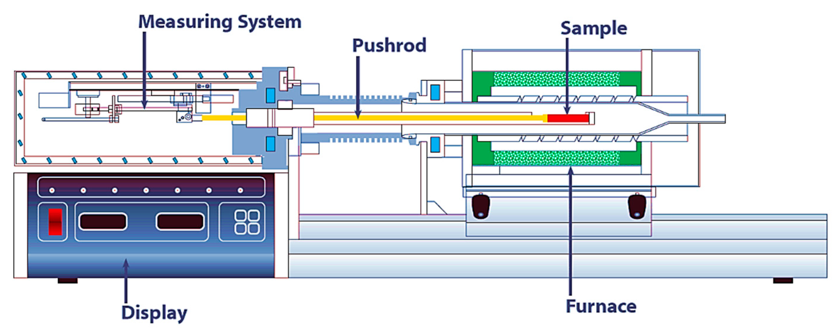
For dilatometric analysis to specify the intercritical region, a LINSEIS DIL L75 PT H (differential horizontal pushrod dilatometer) (LINSEIS Company, Robbinsville, NJ, USA) shown in Figure 2 was used. This analysis was performed on three cylindrical specimens of 5 mm diameter and 20 mm length. A quartz push rod was used to transmit the length change to the linear variable differential transformer. The dilatometric measurements were performed under 240 mN contact force. During the thermal cycle, the dilatometric curve was recorded to determine the intercritical region.

2.3.2. Thermodynamic Software

Thermo-Calc software with the TCFE9 database was used to specify the intercritical region. This software enables calculating the amount and composition of each phase depending on the annealing temperature.

2.3.3. Intercritical Austenitizing Heat Treatment

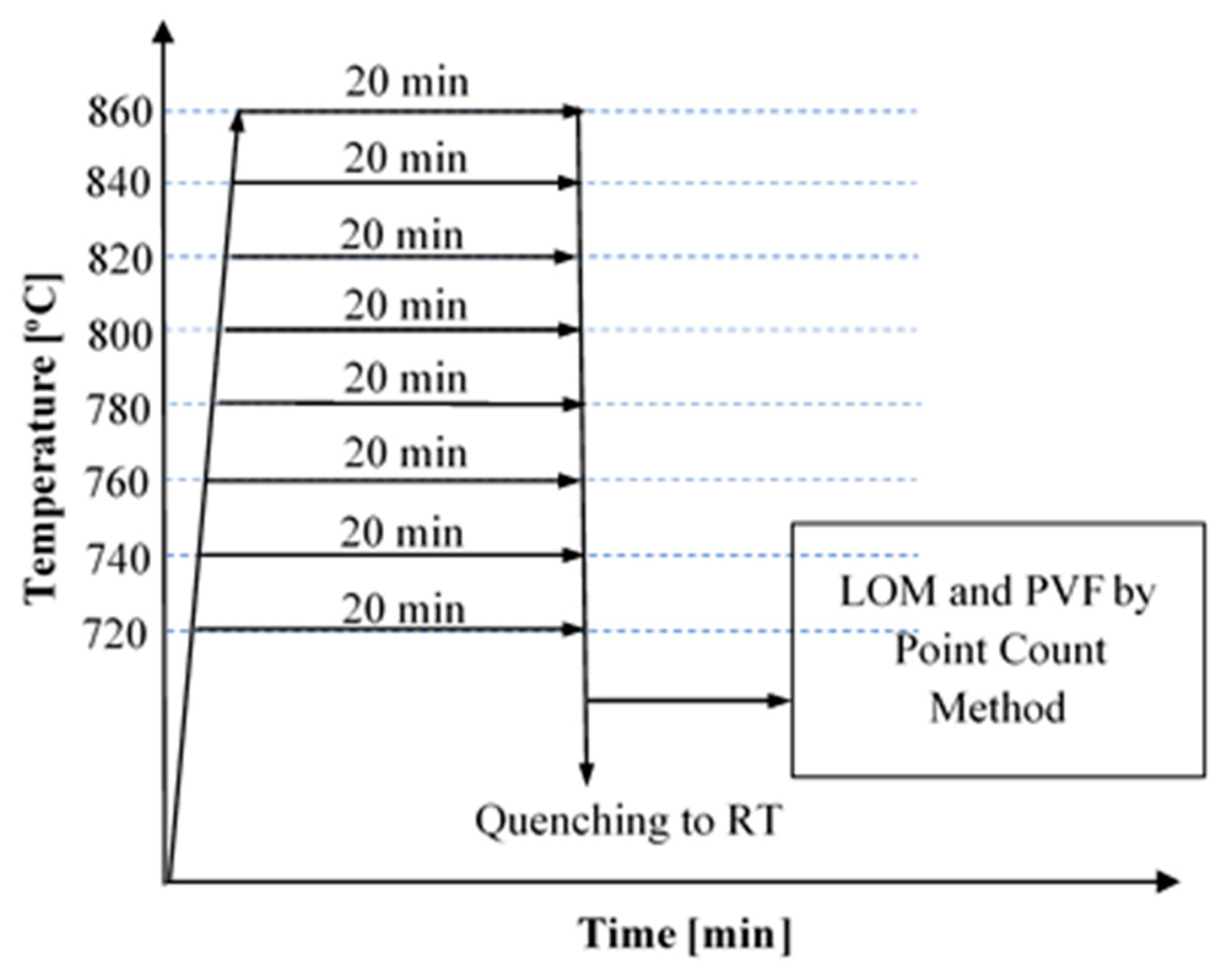
The intercritical region for the as-cast ductile iron was established by the practical methodology described in the previous work [45,46]. According to this knowledge, the samples with dimensions of 15 mm × 15 mm × 5 mm machined from Y-block were subjected to thermal heat treatment cycles involving austenitizing, holding, and quenching stage. Austenitizing stage was performed at temperatures ranging from 720 to 860 °C by 20 °C step. At each austenitizing temperature, the samples are soaked for 20 min and then quenched in water. Figure 3 shows a summary of the thermal heat treatment cycles to determine the intercritical region.

2.4. Aging Treatment

The aging treatment was performed on the DMS-DI with the ferrite-martensite matrix. The specimens were soaked for nine different aging times (2, 10, 20, 50, 100, 500, 1000, 5000, 10,000 min) at aging temperatures of 140, 170, and 220 °C. After aging treatment, the specimens were quenched in water (to terminate carbon diffusion) and then stored frozen at 18 °C (to avoid natural aging) until applying the tensile test. The aging temperatures and times were selected based on the common aging conditions applied on dual-phase steels [47,48].

2.5. Tensile Test

Cylindrical tensile test samples with a gauge length of 25 mm and an original diameter of 5 mm were machined from the lower part of Y-blocks according to ISO 6892-1:2009E [49]. The samples were machined prior to heat treatment cycles to avoid developing of any residual stresses during machining process. The tensile testing was carried out at room temperature using a LLOYD universal testing machine (LLOYD Instruments, UK) with a 300 kN loading capacity and the loading speed (cross head speed) of 1 mm/min. For each aging condition, three samples were tested.

2.6. Hardness Test

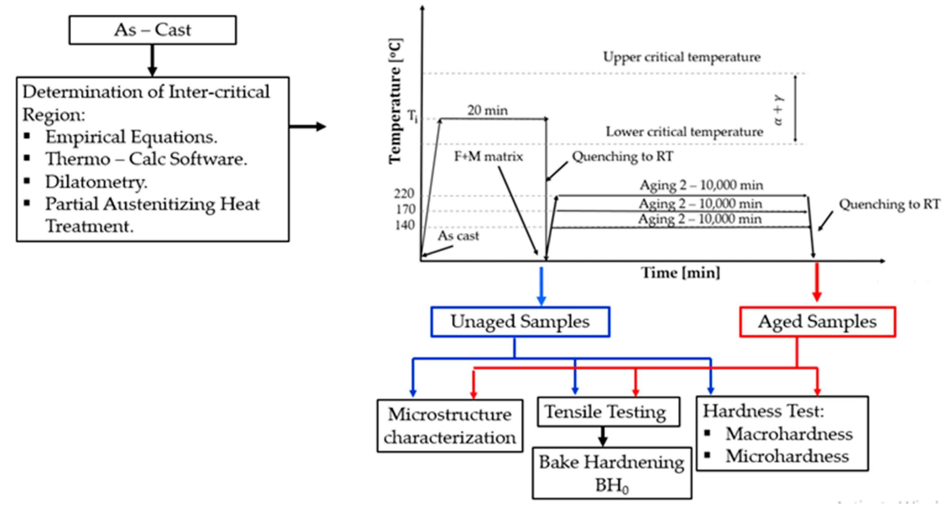
In this study, both macrohardness (surface hardness) and microhardness measurements were performed on as-cast, unaged, and aged DI. For macrohardness measurements, the Wilson Rockwell hardness test with a Rockwell B scale (100 kg load—1/16” tungsten carbide ball) (Instron GmbH, Darmstadt, Germany) was used. For each sample, five indentations were done and the average hardness HRB was calculated. For microhardness measurements, the Mitutoyo microhardness tester (Mitutoyo, Sakado, Japan) with an optical microscope was used. The hardness of all phases in unaged (ferrite-martensite) and after aging (ferrite-martensite) was measured with a Vickers (10 g load, and 15 s duration time) hardness technique. Five Vickers microhardness indentations were applied in each phase. Figure 4 depicts the experimental procedure performed during the current work.

3. Results and Discussion

3.1. Characteristics of the As-Cast

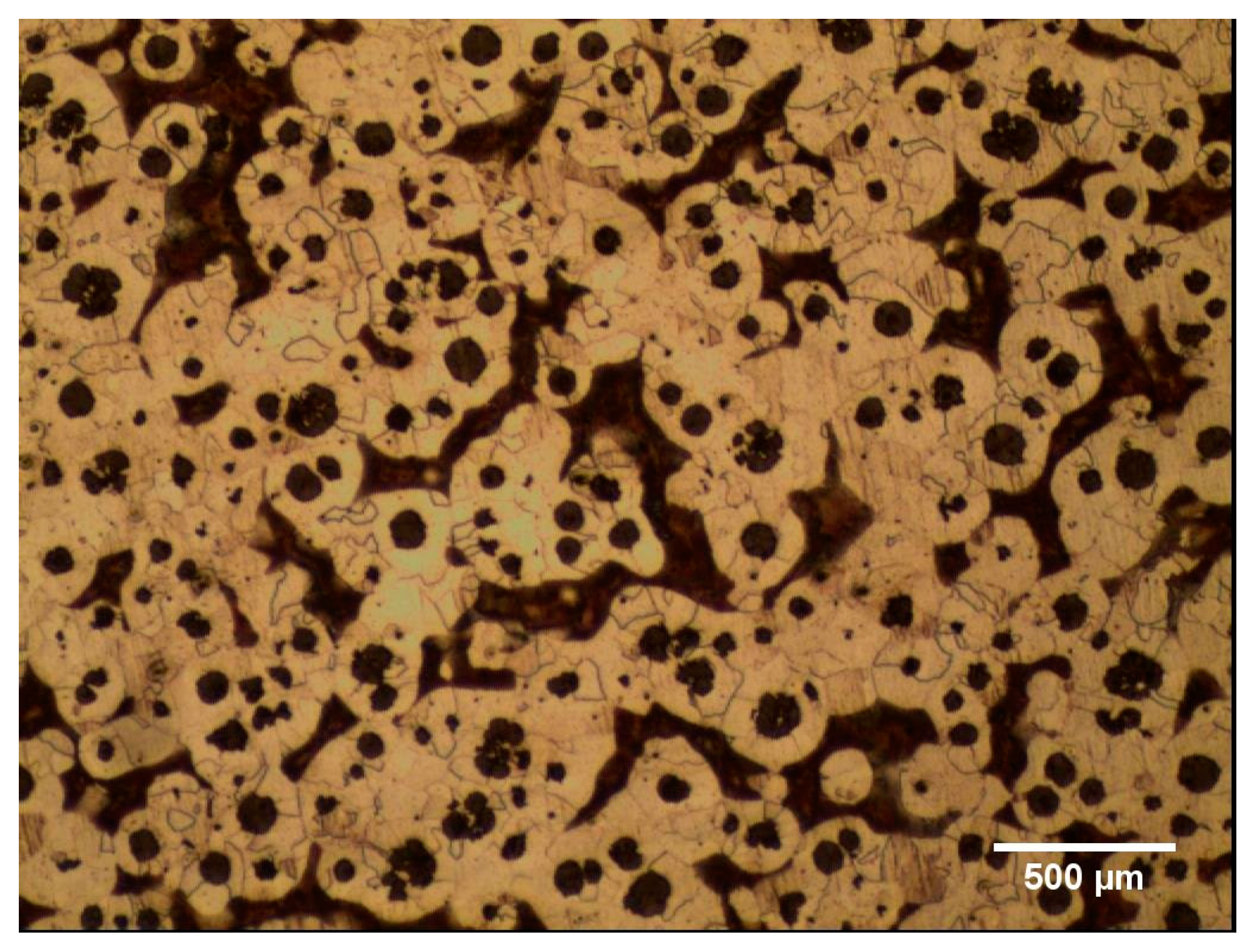
The chemical composition of the as-cast condition is given in Table 1. The Si and Mn contents are the most significant elements that influence the range of intercritical region. These contents are conforming to the recommended values in the literature [50] for characterizing the intercritical region. Figure 5 illustrates the microstructure of the as-cast condition, which consists of a ferritic-pearlitic matrix. The as cast microstructure was composed of 64% ferrite and 36% pearlite. Additionally, the as-cast morphology displayed a nodularity of about 66% according to the requirements of ASTM E2567 standard [51], the nodule size was 26.4 µm, and the nodule count was 227 nodules/mm2.

3.2. The Intercritical Region

For the empirical equations, the lower and upper critical transformation temperatures A e 1 and A e 3 were estimated using empirical equations [52]. Accordingly, the intercritical region range lays 782.7 °C to 813.3 °C.
From the Thermo-Calc calculations, it was found that the formation of austenite begins at 787.8 °C, which is known as the lower critical transformation temperature A e 1 . It was also observed that the end of ferrite formation occurred at 821.3 °C, which is known as the upper critical transformation temperature A e 3 . The intercritical region is characterized by the presence of γ + α + graphite together, and this is only achieved from 787.8 °C to 821.3 °C.
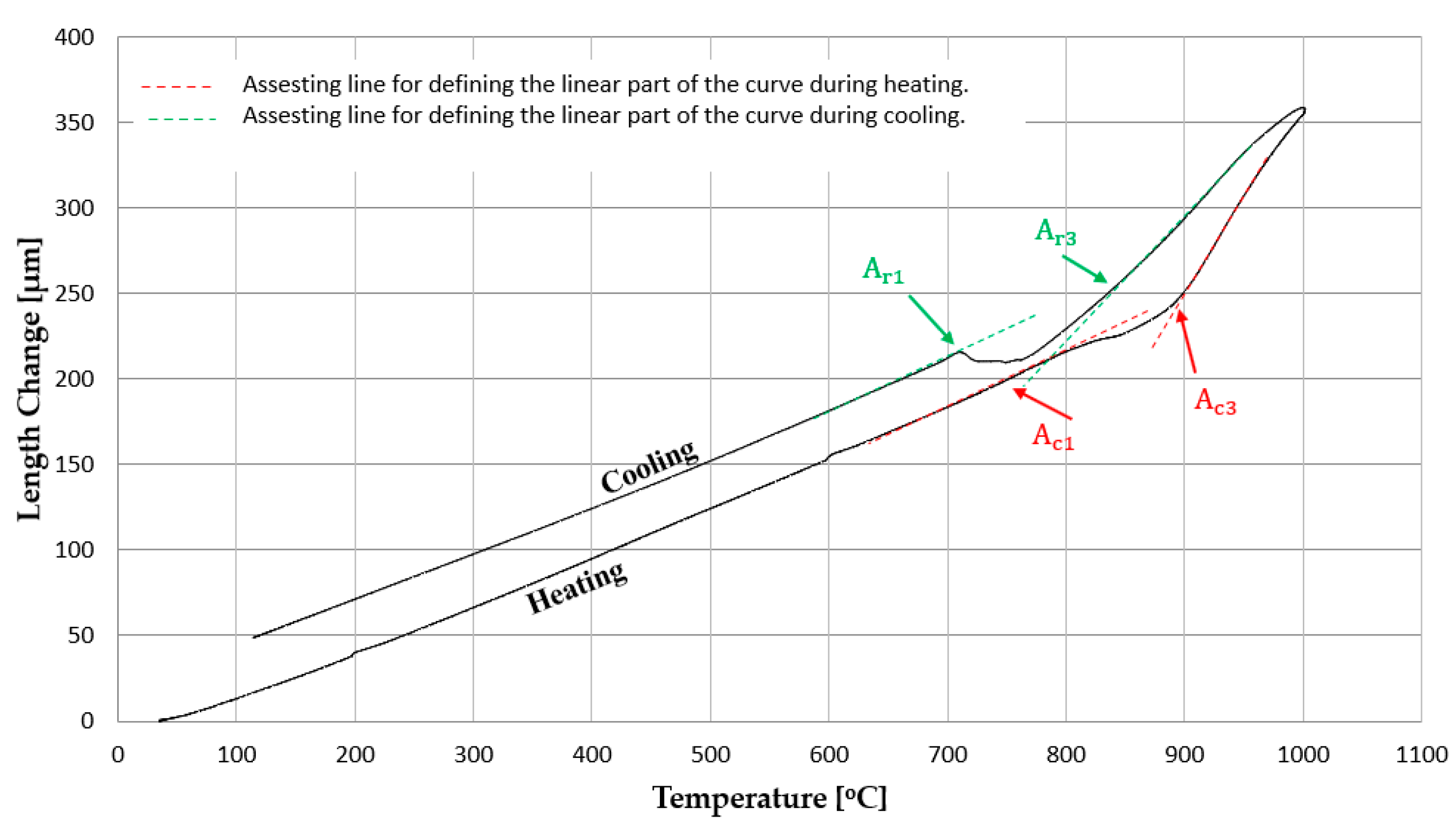
The dilatometric measurements were carried out by heating the samples up to 1000 °C. For confirming the equilibrium measurements, the samples were heated with a heating rate of 0.08 K/s and cooled with a cooling rate of 0.17 K/s to detect the dilatometric (Temperature—length change) curve shown in Figure 6.
From the dilatometry measurements, we find that the curve begins to deviate from linearity at ~755 °C during heating, which indicates the (austenite formation) start of the ferrite to austenite transformation. The curve restores linearity at ~890 °C, indicating the transformation is complete. During cooling, the dilatometric curve deviates from linearity at ~843 °C, indicating the beginning of ferrite formation, and then returns to linearity again at ~714 °C, which corresponds to the end of ferrite formation. Within these temperature ranges (755 to 890 °C during heating and 714 to 843 °C during cooling), the ferrite, austenite, and graphite coexist, and these temperature ranges correspond to the intercritical region.
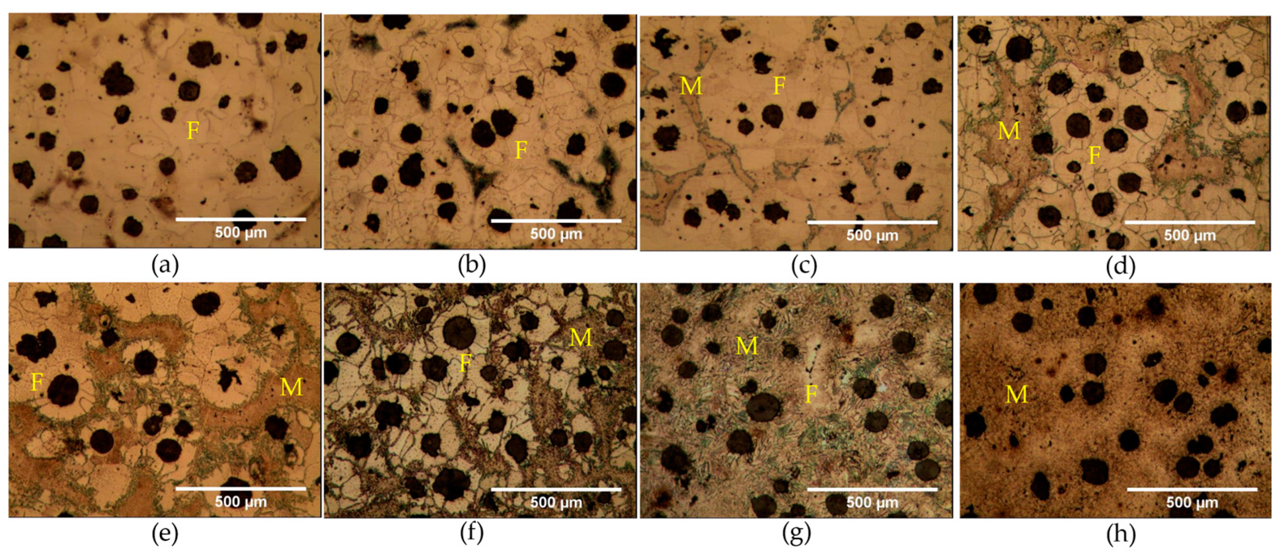
The intercritical region was determined according to the methodology described in the experimental procedure (Section 2.3.3). Partially austenitizing at different temperatures within the intercritical region (α + γ) enables controlling as well as obtaining different amounts of ferrite and martensite. Figure 7 demonstrates the microstructures of ductile iron obtained after austenitizing and water quenching steps. Generally, these microstructures consist of ferrite (labeled F), martensite (labeled M), and graphite (spheroidal graphite). Through this metallographic examination, it can be observed that the martensite was completely formed at 860 °C, indicating that 20 min (holding time) at this austenitizing temperature is sufficient to reach equilibrium.
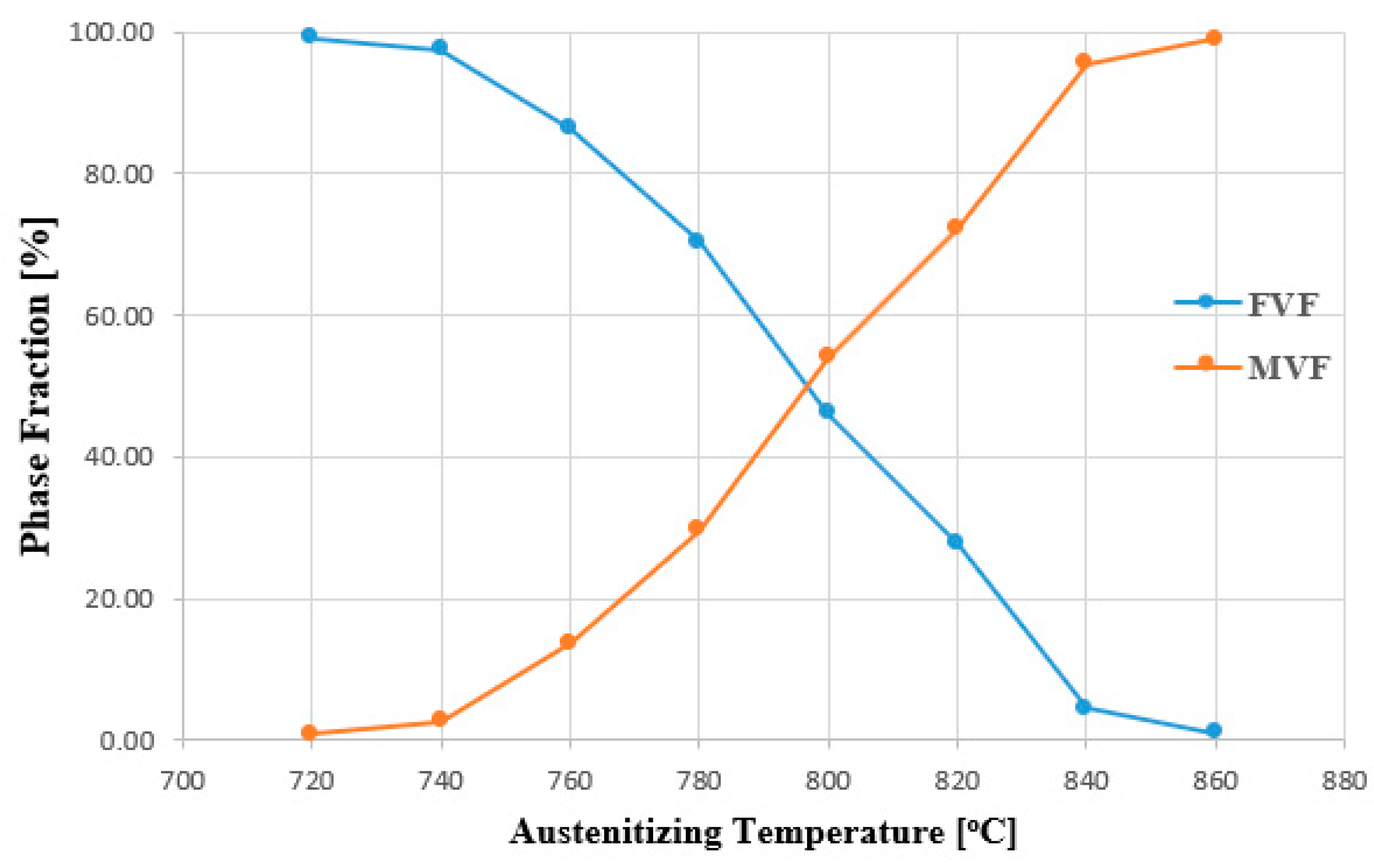
Figure 8 depicts the measured matrix volume fractions of ferrite (FVF) and martensite (MVF) as a function of austenitizing temperature. It is evident that as the partial austenitizing temperature increases, the MVF increases and the FVF decreases. The A e 1 is established at 740 °C, due to the presence of a martensite, produced by quenched austenite. Likewise, the A e 3 is defined as 860 °C, due to the martensite is fully formed.
Table 2 lists the results of characterizing of the intercritical region by the different techniques as described above together with the empirically calculated ones. Based on the results shown in this table, it can be concluded that estimating the range of the intercritical region using dilatometric method by continuous heating is more accurate than the other method.

3.3. Microstructural Analysis

Based on the results obtained from the determination of the intercritical region, the austenitizing temperature of 785 °C within this range was selected to produce the ferrite-martensite DMS-DI. Figure 9 shows the microstructures of the unaged samples after austenitization at 785 °C for 20 min and quenching in water to room temperature. As shown in Figure 9a, the microstructure observed by light optical microscope (LOM) shows a matrix consisting of ferrite (bright color) and martensite (dark color). There may be phases that are not defined under the LOM due to their small size. For this reason, a scanning electron microscope (SEM) was used to elucidate these phases. The SEM micrograph of the unaged samples is presented in Figure 9b. It is also observed that there is an indistinct phase, such as the area denoted by red rectangle in the same figure. Referring to the corresponding micrographs with higher magnification shown in Figure 9c,d, these revealed that the plate martensite morphology was formed by quenching ductile iron to room temperature. These features correspond to the typical morphology of quenched ductile iron [53], but without retained austenite due to austenitization at 785 °C within the intercritical region.
The SEM micrographs of Figure 9 illustrate that the formed martensite is chiefly a plate-type martensite. However, pearlite is formed at the interface with the ferrite phase as shown in Figure 9. The holding time and temperature were not sufficient for dissolving the whole pearlite existing in the as-cast condition. About 1.5% of this phase is retained at the ferrite-martensite interface and appears as a black-phase in the LOM micrographs (Figure 9a) and revealed a fine lamellar structure in the SEM micrographs (Figure 9c,d). The untempered martensite appears as a featureless structure with a higher level compared to the ferrite phase.
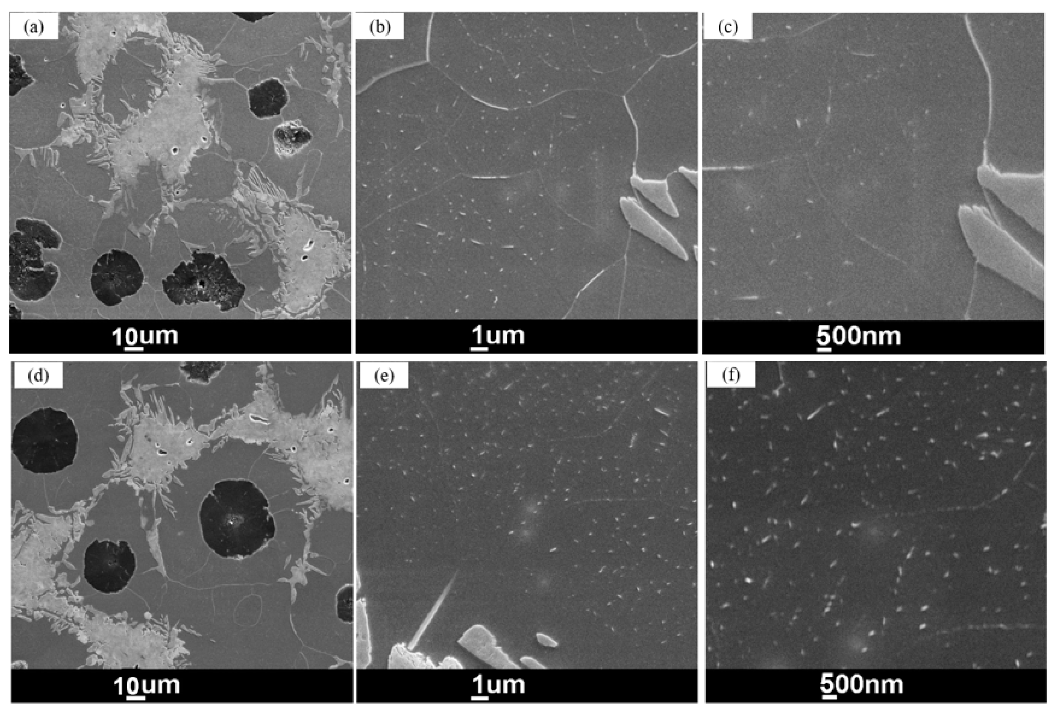
The SEM micrographs of specimens aged at a temperature of 170 °C for a 1000 and 10,000 min are presented in Figure 10. It was observed that after 1000 min, there are visible small needle precipitates in the ferrite. Extending of the aging time up to 10,000 min led to increased needle precipitations. These precipitates are believed to be formed during aging, as they were absent in the unaged condition as shown in Figure 9c,d. As clearly observable in Figure 10b,c,e, the carbide precipitates are rarely evident within a ferrite margin around the ferrite-martensite interface. This observation can be correlated to the lower saturation with carbon at these zones compared to the regions that showed large precipitates [48]. It is predicted using thermodynamic calculations using Thermo-Calc (Thermo-Calc Software AB, Solna, Sweden) that ~0.02 wt.% of C dissolves in ferrite during intercritical annealing. Throughout quenching from the intercritical region to RT, the solubility of carbon in ferrite decreases by decreasing the temperature, which results in diffusion of carbon from ferrite to the austenite/martensite phase during the course of quenching. However, this diffusion process is limited by the short time of quenching, therefore resulting in lower carbon content at the neighborhood of the martensite phase compared to the that far away from it, which require long-range diffusion between phases [48].

3.4. Mechanical Properties of the Aged DMS-DI

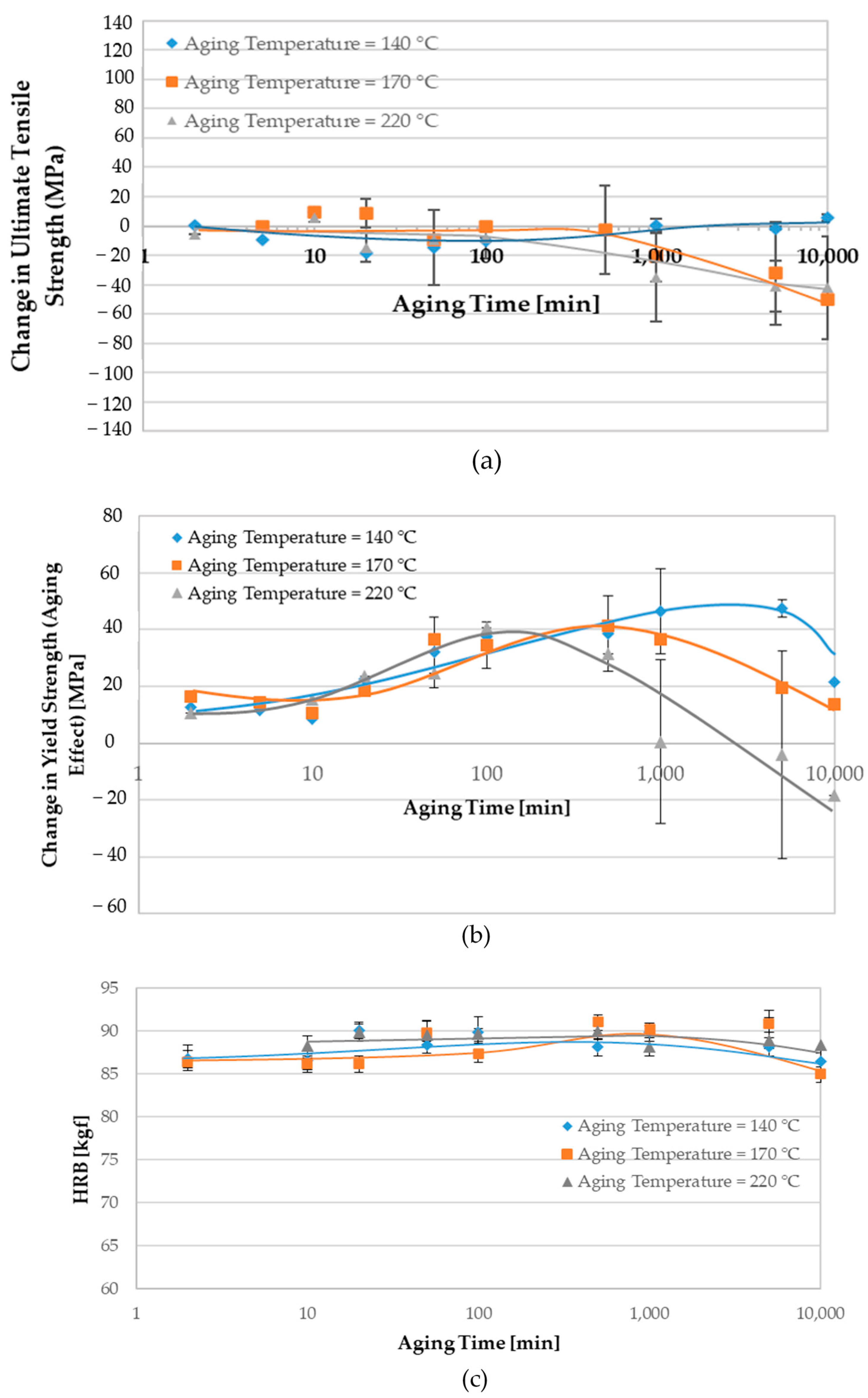
The mechanical properties of the DMS-DI before aging treatment are summarized in Table 3. As mentioned above, the specific aim of this research is to study the effect of aging treatment on the mechanical properties of the ductile iron with the ferrite-martensite matrix structure. To assess the influence of aging on the mechanical properties, the tensile and hardness properties were evaluated before and after aging. Figure 11 shows the effect of aging temperature and time on tensile and hardness properties for samples intercritically annealed at 785 °C and aged at temperatures of 140, 170, and 220 °C for aging times from 2 to 10,000 min.
In unaged condition, the samples had relatively higher ultimate tensile strength (UTS) due to the presence of the untempered plate martensite. At the lowest aging temperature of 140 °C, the (UTS) has not shown a significant change with increasing the aging time as shown in Figure 11a. A significant decrease in the UTS for the samples aged at 170 and 220 °C is observed with prolonged aging time. The decreasing in UTS starts at about 500 min and 100 min of holding at 170 °C and 220 °C, respectively.
The aging response (BH0 level) of the DMS-DI was calculated from the difference between the 0.2% offset yield strength after and before aging process. Figure 11b shows the strengthening stages of aging process without pre-straining as a function of aging time. In iron carbon alloys, it is a known fact that the mechanical properties may be affected by solute atoms (carbon and nitrogen) diffusion according to the mechanisms:
  • Stress-induced arrangement of solute atoms in interstitial sites (Snoek effect).
  • Segregation of solute atoms into dislocations to form and stabilize a Cottrell atmosphere.
  • Precipitation of carbides.
In general, the phenomenon of aging is based on the diffusion rate of interstitial atoms towards dislocations. The increase in the yield strength (YS) goes through two plateaus as shown in Figure 11b. The maximum level of BH0 is achieved in the samples aged at 140, 170, and 220 °C for an aging time of 5000, 500, and 100 min, respectively. It is clear that the aging temperature plays a significant effect in the aging kinetics; increasing the aging temperature pronouncedly accelerates it. The effect of aging temperature on the achieved BH0 responses in the lower and upper plateaus is rather limited.
Although there is no available research indicating that formation of a Cottrell atmosphere in DMS-DI, some research works [47,48] performed on dual-phase steel suggest that the first increase in yield strength (first plateau) is caused by Cottrell atmosphere. In this strengthening stage, the all-aged samples exhibited almost the same aging response during the short aging time. A subsequent strengthening stage is observed due to the formation of the precipitates (Figure 10b,c,e,f). At this stage, the BH0 value is mainly dependent on the aging temperature and aging time as a result of carbides precipitation. These precipitates were absent in the unaged condition (Figure 9).
A slightly decrease in BH0 level is observable for samples aged for 10 min at 140 °C and at 170 °C. This behavior can be attributed to the weakening of dislocations locking by the Cottrell atmosphere. Prolonging the aging process, the effect of the over-aging treatment is observed, and the yield strength (BH0 level) decreases after reaching the maximum value. This effect can be observed at the early aging times of 1000, 500, and 100 min when aging at 140, 170, and 220 °C, respectively. The decrease in strength can be attributed to the martensite tempering as well, which will be shown in the next section.
The measured Rockwell hardness B (HRB) as a function of aging time is shown in Figure 11c. Ductile iron with ferrite + martensite matrix does not exhibit the hardness plateau and over-aging effect associated with the traditional aging phenomenon; instead, the hardness fluctuated within a range of less than 5%, i.e., within the experimental error range.

3.5. Microhardness

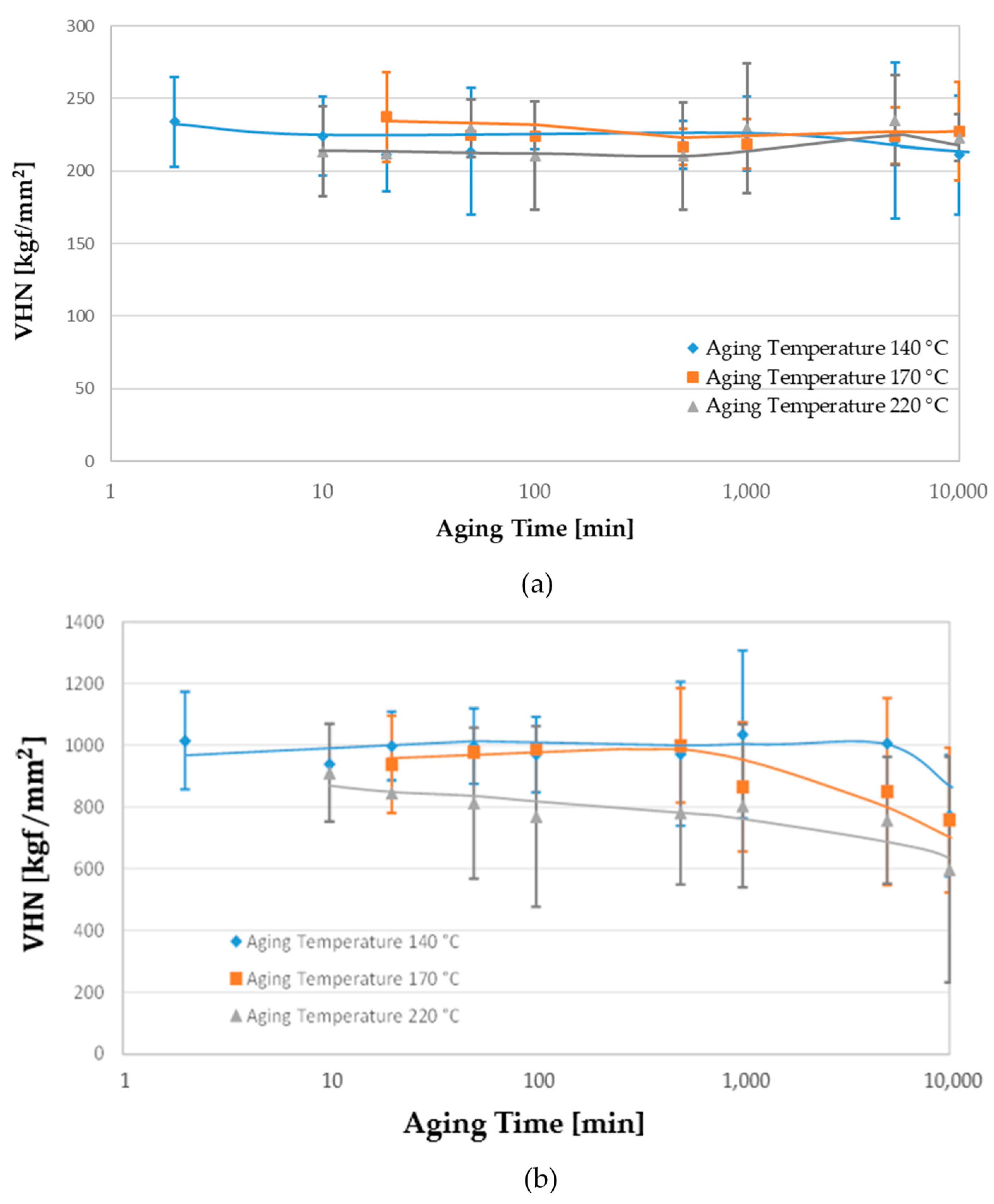
Microhardness tests were carried out to estimate the changes occurring in the ferrite and martensite phase due to aging treatments. The Vickers microhardness of the ferrite and martensite as a function of both the aging temperature and time are depicted in Figure 12.
Figure 12 shows that the aging has no significant effect on the micro-hardness of the ferrite, whereas the martensite hardness declines with increasing the aging time. This observation is revealed in Figure 13, where the size microhardness indentation of the DMS-DI before aging and after aging for 1000 min and 10,000 min are almost similar. However, the indentation-size in martensite increases by increasing the aging time, indicating a decrease in hardness. Therefore, the formed precipitates in ferrite during aging (Figure 10) has not resulted in a significant increase in hardness. This might be due to the fact that the aging process is accompanied by decreasing the supersaturation of carbon in the ferrite as mentioned before. Additionally, Shan et al. showed analytically that the carbon saturating ferrite in the case of dual-phase steel decreases during the aging process [54]. A similar phenomenon is also expected in DMS-DI. Therefore, the increase in strength due to precipitates formation is counteracted by a decrease in solid solution strengthening of ferrite. This may justify the observation that aging the DMS-DI has not resulted in increasing the macrohardness. Furthermore, the ferrite regions that appeared under LOM and SEM as free of the needle precipitates showed similar microhardness as that with the precipitates. This can be also deduced from the similarity of indentation sizes within the former regions in Figure 13c,d with the latter regions in Figure 13b,d.
The decline in the hardness of the martensite (Figure 12b) is also revealed in Figure 13a–c. Figure 12b shows that this decrease starts to be more significant after different times depending on the aging temperature. These martensite tempering times correspond to the decay in the BH0 values (compare Figure 11b with Figure 12b). Therefore, the over-aging phenomenon is closely related to the martensite tempering in DMS-DI.
The high Si content of the investigated ductile iron has a direct effect on the activation energy of aging process, which affects the yielding behavior; the silicon in solid solution reduces the diffusivity of carbon atoms in the ferrite phase [55]. The investigated ductile iron in this work has about 2.63 wt.% silicon, which is very high compared to most steels. Finally, in order to be able to develop a basic understanding of the aging process in ferrite + martensite ductile iron, an extensive research effort is still required.

4. Conclusions

This study is an attempt to understand the aging behavior of DMS-DI. DMS-DI with MVF of ~30% was produced by austenitizing in the intercritical region followed by quenching in water to room temperature. The effect of aging process on the mechanical properties was investigated. The increase in yield strength (BH0 response) was investigated for aged samples. Based on the experimental results in this study, the following conclusions are obtained:
  • The estimating range of the intercritical region by dilatometric method applying continuous heating transformation is more accurate than that estimated by ThermoCalc software and empirical equations. The latter two methods overestimate the lower and underestimate the upper critical transformation temperatures by about +45 °C and −43 °C, respectively.
  • For all investigated aged samples, the aging conditions have no major effect on the ultimate tensile strength UTS and macro hardness.
  • The increase in yield strength BH0 value (~11% increase) associated with the aging process is observed to go through two strengthening stages followed by a decrease in BH0 value (over-aging).
  • The maximum BH0 is found to be achieved after aging for 100, 500, and 5000 min when aging at 220 °C, 170 °C, and 140 °C, respectively.
  • The over-aging in DMS-DI is found to be closely related to the martensite tempering, which was revealed by microhardness measurements. The decrease in the martensite hardness starts to be more significant after aging times corresponding to the over-aging start-times.
  • The aging process has no significant effect on the microhardness of the ferrite phase in DMS-DI, which recorded a HV0.01 value of about 235 kgf/mm2.

Author Contributions

Conceptualization, M.S. and A.E.; data curation, A.A.; formal analysis, A.A., and M.S.; investigation, A.A.; methodology, A.A., M.S., and A.E.; project administration, A.A. and A.E.; resources, M.S., H.P., and A.E.; software, M.S.; supervision, M.S. and A.E.; validation, A.A.; visualization, A.A. and M.S.; writing—original draft, A.A. and M.S.; writing—review and editing, H.P. and A.E. All authors have read and agreed to the published version of the manuscript.

Funding

This research received no external funding.

Institutional Review Board Statement

Not applicable.

Informed Consent Statement

Not applicable.

Data Availability Statement

The data presented in this study are available on request from the corresponding author. The data are not publicly available at this time as they form part of an ongoing study.

Conflicts of Interest

The author declares no conflict of interest.

References

  1. Murcia, S.C.; Paniagua, M.A.; Ossa, E.A. Materials science & engineering a development of As-cast dual matrix structure (DMS) ductile iron. Mater. Sci. Eng. A 2013, 566, 8–15. [Google Scholar] [CrossRef]
  2. Lacaze, J.; Sertucha, J.; Åberg, L.M. Microstructure of As-cast ferritic-pearlitic nodular cast irons. ISIJ Int. 2016, 56, 1606–1615. [Google Scholar] [CrossRef] [Green Version]
  3. Soliman, M.; Nofal, A.; Palkowski, H. Alloy and process design of thermo-mechanically processed multiphase ductile iron. Mater. Des. 2015, 87, 450–465. [Google Scholar] [CrossRef]
  4. Gonzaga, R.A. Influence of ferrite and pearlite content on mechanical properties of ductile cast irons. Mater. Sci. Eng. A 2013, 567, 1–8. [Google Scholar] [CrossRef]
  5. Rashidi, A.M.; Rashidi, A.M. Dual matrix structure (DMS) ductile cast iron: The effect of heat treating variables on the mechanical properties. Int. J. Cast Met. Res. 2016, 13, 293–297. [Google Scholar] [CrossRef]
  6. Soliman, M.; Ibrahim, H.; Nofal, A.; Palkowski, H. Thermo-mechanically processed dual matrix ductile iron produced by continuous cooling transformation. J. Mater. Process. Technol. 2016, 227, 1–10. [Google Scholar] [CrossRef]
  7. Sikora, J.; Basso, A. Review on production processes and mechanical properties of dual phase austempered ductile iron. Int. J. Met. 2012, 6, 7–14. [Google Scholar]
  8. Soliman, M.; Palkowski, H.; Nofal, A. Thermo-mechanically processed multi-phase ductile iron: Microstructure development. Key Eng. Mater. 2011, 457, 199–204. [Google Scholar] [CrossRef]
  9. Kocatepe, K.; Cerah, M.; Erdogan, M. Effect of martensite volume fraction and its morphology on the tensile properties of ferritic ductile iron with dual matrix structures. J. Mater. Process. Technol. 2006, 178, 44–51. [Google Scholar] [CrossRef]
  10. Erdogan, M.; Kilicli, V.; Demir, B. Transformation characteristics of ductile iron austempered from intercritical austenitizing temperature ranges. J. Mater. Sci. 2009, 44, 1394–1403. [Google Scholar] [CrossRef]
  11. Mozumder, Y.H. Influence of Intercritical Austenitizing Temperature, Quenching Media and Tempering Temperature on Mechanical Properties and Wear Behavior of Ductile Iron with Dual Matrix Structure Metallurgical and Materials Engineering National Institute of Technology. Ph.D. Thesis, National Institute of Technology Rourkela, Odisha, India, 2015. [Google Scholar]
  12. Basso, A.; Martínez, R.; Sikora, J.; Sikora, J. Influence of section size on dual phase ADI microstructure and properties: Comparison with fully ferritic and fully ausferritic matrices Influence of section size on dual phase ADI microstructure and properties: Comparison with fully ferritic and fully. Mater. Sci. Technol. 2013, 25, 1271–1278. [Google Scholar] [CrossRef]
  13. Sikora, J.A.; Basso, A.D.; Martı, R.A. Influence of austenitising and austempering temperatures on microstructure and properties of dual phase ADI. Mater. Sci. Technol. 2007, 23, 1321–1327. [Google Scholar] [CrossRef]
  14. Basso, A.; Caldera, M.; Rivera, G.; Sikora, J. High silicon ductile iron: Possible uses in the production of parts with “dual phase ADI”. Microstructure 2012, 52, 1130–1134. [Google Scholar]
  15. Wang, S.C.; Starink, M.J. Precipitates and intermetallic phases in precipitation hardening Al-Cu-Mg-(Li) based alloys. Int. Mater. Rev. 2005, 50, 193–215. [Google Scholar] [CrossRef] [Green Version]
  16. Age Hardening—Metallurgical Processes. Available online: https://www.azom.com/article.aspx?ArticleID=9623 (accessed on 13 August 2013).
  17. Avner, S.H. Introduction to Physical Metallurgy, 2nd ed.; New York City Community College, City University of New York: New York, NY, USA, 1974; ISBN 0070024995. [Google Scholar]
  18. Askeland, D.R.; Fulay, P.P. Essentials of Materials Science and Engineering, 2nd ed.; Cengage Learning: Belmont, CA, USA, 2009; ISBN 9780495438502. [Google Scholar]
  19. Callister, W.D.; Rethwisch, D.G. Materials Science and Engineering: An Introduction, 18th ed.; Wiley: New York, NY, USA, 2013; Volume 53, ISBN 9788578110796. [Google Scholar]
  20. Pereloma, E.; Timokhina, I. Bake Hardening of Automotive Steels; Elsevier Ltd.: Amsterdam, The Netherlands, 2016; ISBN 9780081006535. [Google Scholar]
  21. Elsen, P.; Hougardy, H.P. On the mechanism of bake-hardening. Steel Res. 1993, 64, 431–436. [Google Scholar] [CrossRef]
  22. Teague, J.; Richards, V. Age strengthening of cast irons: Review of research and literature. Int. J. Met. 2010, 4, 45–57. [Google Scholar] [CrossRef]
  23. Catalina, A.V.; Buhrig-Polaczek, A.; Monroe, C.; Sabau, A.S.; Richards, V.L. Age-Strengthening of Cast Iron and Its Effects on Machinability: Review of the Literature. In Advances in the Science and Engineering of Casting Solidification: An MPMD Symposium Honoring Doru Michael Stefanescu; John Wiley and Sons: New York, NY, USA, 2015; pp. 269–276. [Google Scholar]
  24. Gokhale, S.P. Aging of Austempered Ductile Irons; University of New Brunswick: Fredericton, NB, Canada, 1995. [Google Scholar]
  25. Rezvani, M. Precipitation Hardening for Ferritic Ductile Iron; University of Birmingham: Birmingham, UK, 1996. [Google Scholar]
  26. Nicola, W.M.; Richards, V. Age strengthening of gray cast iron, phase I: Statistical verification. AFS Trans. 1999, 107, 233–237. [Google Scholar]
  27. Nicola, W.M.; Richards, V.L. Age strengthening of gray cast iron, phase II: Nitrogen and melting method effects. AFS Trans. Am. Foundry Soc. 2000, 108, 233–237. [Google Scholar]
  28. Lekakh, S.N.; Richards, V.L. Aging and machinability interactions in cast iron. Trans. Am. Foundry Soc. 2012, 120, 307–318. [Google Scholar]
  29. Richards, V.L.; Lekakh, S.N.; Teague, J.; Peaslee, K.D. Aging and machinability of irons with compact and spheroidal graphite. Trans. Am. Foundry Soc. 2010, 118, 10–36. [Google Scholar]
  30. Richards, V.L.; Van Aken, D.C.; Nicola, W. Age strengthening of gray cast iron. Int. J. Cast Metals Res. 2016, 16, 275–280. [Google Scholar] [CrossRef]
  31. Richards, V.L.; Van Aken, D.C.; Nicola, W. Age strengthening of gray cast iron: Kinetics, mechanical property effects. AFS Trans. 2003, 111, 733–742. [Google Scholar]
  32. Edington, J.; Nicola, W.; Richards, V.L. Age strengthening of gray cast iron: Nitrogen effects and machinability. AFS Trans. 2002, 110, 983–993. [Google Scholar]
  33. Nicola, W.M.; Richards, V. Age strengthening of gray cast iron phase III—Effect of aging temperature. AFS Trans. 2001, 81, 1–9. [Google Scholar]
  34. Richards, L.; Nicola, W. Final Technical Report: Age Strengthening of Gray Cast Iron Phase iii Summary of Activities Discussion of Results List of Papers Produced during This Contract; University of Missouri-Rolla: Rolla, MO, USA, 2003. [Google Scholar]
  35. Teague, J.A.; Richards, V.L.; Lekakh, S.N.; Peaslee, K.D. Age strengthening and machinability interactions in gray cast iron. AFS Trans. 2009, 117, 475. [Google Scholar]
  36. Anish, T.; Lekakh, S.N.; Richards, V.L. The effect of Ti and N on iron age strengthening. AFS Trans. 2008, 116, 653. [Google Scholar]
  37. Richards, V.L.; Van Aken, D.C.; Mereau, O.P.; Nicola, W.M. Effects of room temperature aging on ductile iron. AFS Trans. 2004, 38, 1–12. [Google Scholar]
  38. Richards, V.L.; Anish, T.V.; Lekakh, S.; Van Aken, D.C.; Nicola, W. Composition effects on age strengthening of gray iron. AFS Trans. 2006, 114, 507. [Google Scholar]
  39. Teague, J.A.; Richards, V.L.; Lekakh, S.N.; Peaslee, K.D. Aging effect on gray cast iron machinability: Tool force and tool wear. AFS Trans. 2008, 116, 733. [Google Scholar]
  40. Lekakh, S.N.; Richards, V.L.; Medvedeva, J.; Murphy, J.M. Effect of alloying elements on gray iron natural aging, part 1: Manganese. AFS Trans. 2011, 119, 379. [Google Scholar]
  41. Bayati, H.; Elliott, R. Aging Process of Alloyed ADI. In Proceedings of the Second International Conference on Processing Materials for Properties, San Francisco, CA, USA, 5–8 November 2000; pp. 77–82. [Google Scholar]
  42. Radzikowska, J.M. Metallography and microstructures of cast iron. ASM Handb. Metallogr. Microstruct. 2004, 9, 565–587. [Google Scholar] [CrossRef]
  43. ASTM. Standard Test Method for Determining Volume Fraction by Systematic Manual Point Count; ASTM: West Conshohocken, PA, USA, 2008; pp. E562–E568. [Google Scholar]
  44. DIL L75 PT Horizontal. Available online: https://www.linseis.com/en/products/dilatometer/dil-l75-pt-horizontal/ (accessed on 25 May 2021).
  45. Basso, A.; Martínez, R.; Sikora, J. Influence of chemical composition and holding time on austenite (γ)→ ferrite (α) transformation in ductile iron occurring within the intercritical interval. J. Alloys Compd. 2011, 509, 9884–9889. [Google Scholar] [CrossRef]
  46. Zhang, H.; Wu, Y.; Li, Q.; Hong, X. Mechanical properties and rolling-sliding wear performance of dual phase austempered ductile iron as potential metro wheel material. Wear 2018, 406–407, 156–165. [Google Scholar] [CrossRef]
  47. Soliman, M.; Palkowski, H. Tensile properties and bake hardening response of dual phase steels with varied martensite volume fraction. Mater. Sci. Eng. A 2020, 777, 139044. [Google Scholar] [CrossRef]
  48. Soliman, M.; Shan, Y.V.; Mendez-Martin, F.; Kozeschnik, E.; Palkowski, H. Strain aging characterization and physical modelling of over-aging in dual phase steel. Mater. Sci. Eng. A 2020, 788, 139595. [Google Scholar] [CrossRef]
  49. ISO. 6892-1. Metallic Materials—Tensile Testing—Part 1: Method of Test at Room Temperature; ISO: Geneva, Switzerland, 2009. [Google Scholar]
  50. Chakrabarty, I. Heat Treatment of Cast Irons; Elsevier: Amsterdam, The Netherlands, 2017; Volume 2, ISBN 9780128035818. [Google Scholar]
  51. ASTM. ASTM E2567—11 Standard Test Method for Determining Nodularity and Nodule Count in Ductile Iron Using Image Analysis; ASTM: West Conshohocken, PA, USA, 2011. [Google Scholar]
  52. Ghergu, R.M.; Sertucha, J.; Thebault, Y.; Lacaze, J. Critical temperature range in standard and Ni-bearing spheroidal graphite cast irons. ISIJ Int. 2012, 52, 2036–2041. [Google Scholar] [CrossRef] [Green Version]
  53. Wang, C.; Chen, Y.; Han, J.; Ping, D.; Zhao, X. Microstructure of ultrahigh carbon martensite. Prog. Nat. Sci. Mater. Int. 2018, 28, 749–753. [Google Scholar] [CrossRef]
  54. Shan, Y.V.; Soliman, M.; Palkowski, H.; Kozeschnik, E. Modeling of bake hardening kinetics and carbon redistribution in dual-phase steels. Steel Res. Int. 2021, 92. [Google Scholar] [CrossRef]
  55. Jalava, K.; Laine, J.; Vaara, J.; Frondelius, T.; Orkas, J.; Jalava, K. Investigation on dynamic strain aging behaviour of ferritic-pearlitic ductile cast irons. Mater. Sci. Technol. 2019, 36, 1–8. [Google Scholar] [CrossRef]
Figure 1. (a) Dimensions of Y block and, (b) Y-shape sand mold.
Metals 11 00897 g001
Figure 2. Schematic drawing of the dilatometer DIL L75 PT [44].
Metals 11 00897 g002
Figure 3. Summary of the intercritical austenitizing heat treatment cycles to produce DMS-DI; RT (room temperature), LOM (light optical microscopy), and PVF (phase volume fraction).
Metals 11 00897 g003
Figure 4. Schematic diagram of the experimental procedures followed in this work: Ti (intercritical” annealing temperature), F (ferrite), M (martensite), RT (room temperature).
Metals 11 00897 g004
Figure 5. Microstructure of as-cast with ferritic-pearlitic matrix.
Metals 11 00897 g005
Figure 6. Dilatation temperature curve during heating with 0.08 (K/s) and cooling with 0.17 (K/s).
Metals 11 00897 g006
Figure 7. Microstructures of ductile iron obtained after austenitizing and water quenched: (a) 720 °C, (b) 740 °C, (c) 760 °C, (d) 780 °C, (e) 800 °C, (f) 820 °C, (g) 840 °C, (h) 860 °C, F (ferrite), M (martensite).
Metals 11 00897 g007
Figure 8. Measured phase fractions (respecting the DI matrix) as a function of austenitizing temperature, FVF (ferrite volume fraction), MVF (martensite volume fraction).
Metals 11 00897 g008
Figure 9. Microstructure of ferrite-martensite matrix (unaged), (a) LOM, (b) SEM, (c) and (d) SEM micrographs with high magnifications of area indicated by red rectangle in (b).
Metals 11 00897 g009
Figure 10. Typical SEM micrographs of samples aged at 170 °C, (ac) for 1000 min, (df) for 10,000 min.
Metals 11 00897 g010
Figure 11. The effect of aging temperature and aging time on the tensile and hardness properties of aged DI with DMS: (a) Change in ultimate tensile strength UTS, (b) change in yield strength YS, and (c) hardness (HRB).
Metals 11 00897 g011
Figure 12. The effect of temperature and aging-time on the microhardness: (a) Ferrite microhardness, (b) martensite microhardness.
Metals 11 00897 g012
Figure 13. Microhardness indentation (denoted by red circles); (a) unaged, (b) 170 °C—1000 min, (c) and (d) 170 °C—10,000 min aging time.
Metals 11 00897 g013
Table 1. Chemical composition of as-cast ductile iron (wt.%).
CSiMnMgSPFeCE1
3.392.630.330.030.010.05Bal. 4.27
CE 1 = %   C + 1 3   ( %   Si + %   P ) .
Table 2. Results of the intercritical region by four different techniques.
Technique
Empirical EquationsThermoCalc SoftwareDilatometryPartial Austenitizing Heat Treatment
TemperatureHeating
A c 1 A c 3
Cooling
A r 3 A r 1
Lower critical transformation temperature [°C]782.7787.8755714740
Upper critical transformation temperature [°C]813.3821.3890843860
Table 3. The mechanical properties of the DMS-DI before aging treatment: UTS (ultimate tensile strength), YS (yield strength 0.2% offset stress), TEL (total elongation), HRB (Rockwell hardness B), FMH (ferrite microhardness, MMH (martensite microhardness), and E (elastic modulus).
UTS [MPa]YS [MPa]TEL [%]HRBFMH [kgf/mm2]MMH [kgf/mm2]E [GPa]
554.33   ± 14.14 402.33   ±   3.97 4.52   ±   2.11 85.8   ±   1.48 235.3   ±   2.59 1029   ±   15.01154.6 ± 25.11
Publisher’s Note: MDPI stays neutral with regard to jurisdictional claims in published maps and institutional affiliations.