Article

Multi-Objective Optimization of Process Parameters to Enhance Efficiency in the Shoe-Type Centerless Grinding Operation for Internal Raceway of Ball Bearings

Faculty of Mechanical Engineering, University of Economics—Technology for Industries, 456 Minh Khai Street, Vinh Tuy Ward, Hai Ba Trung District, Hanoi 11622, Vietnam
Metals 2021, 11(6), 893; https://doi.org/10.3390/met11060893
Submission received: 9 May 2021 / Revised: 27 May 2021 / Accepted: 28 May 2021 / Published: 30 May 2021

Abstract

:
In this article, new research on the multi-objective optimization of the process parameters applied to enhance the efficiency in the shoe-type centerless grinding operation for the inner ring raceway of the ball bearing made from SUJ2 alloy steel is presented. The four important input parameters for this process, which included the normal feed rate of fine grinding (Snf), the speed of the workpiece (Vw), the cutting depth of fine grinding (af), and the number of ground parts (Np), were investigated. The aim of the study was to find the most appropriate value set of process parameters in order to, simultaneously minimize the grindstone wear (Gw), maximize the material removal rate (MRR) and the total number of ground parts in a grinding cycle (N’p), while guaranteeing other technology requirements such as surface roughness Ra ≤ 0.5 (µm), oval level Op ≤ 3 (µm), etc. In order to solve the problem, based on the experimental data, in which the grindstone wear was measured online by a measuring system consisting of two pneumatic probes, the optimization of the target functions of Gw, N’p, and MRR and mathematical models that express the dependencies of outcome parameters Gw, Ra, Op, MRR, etc. on the process parameters were determined. Therefore, a global optimal solution of such a discrete and nonlinear multi-objective optimization problem was solved by using a genetic algorithm, presenting the most appropriate process parameters as follows: Snf = 15.38 (µm/s), Vw = 6.00 (m/min), af = 11.76 (µm), and Np = 20 (parts/cycle). In addition, the impact of the four process parameters (Snf, Vw, af, Np) on the wear of the grinding wheel (Gw), the oval level of parts (Op), and the surface roughness of parts (Ra) was evaluated. The discovered technology mode has been applied to the real machining process for the inner ring raceway of the 6208_ball bearing made from SUJ2 alloy steel, and the outcome showed a much better result in comparison with default setting modes, while still ensuring the technology requirements. The difference between the predicted values and the real values of the parameters Gw, Ra, Op, and MRR were controlled within 5% of the ranges.

Graphical Abstract

1. Introduction

Bearings have long been widely utilized in various industries, and requirements for precision bearings have been increasing significantly in the continual pursuit of perfect quality and high-performance products [1]. The raceway surface is the working surface of the bearings; its machining quality directly affects the durability and rotational accuracy of the bearings [1,2]. The shoe-type centerless grinding (STCG) is one of the most important processing methods used in the manufacture of bearing raceways because of its high productivity, technological reliability, and the possibility of full automation [3,4]. This processing method makes it possible to ensure the high accuracy of the size and shape of products and also a high degree of automation of both machine tools and automatic lines. However, the shoe-type centerless grinding process is much different than the conventional grinding methods studied previously [1,4]. This is the centerless outer/inner cylindrical surface grinding process. The location of the center axis of the ring will be changed while grinding, along with the material removal [1,4]. This grinding process includes three stages: the rough grinding stage, the fine grinding stage, and the spark-out grinding stage. In different stages, the parameters are also different. Therefore, the grinding process on the bearing ring raceway surface is much more complicated, which will bring many difficulties for research. Thus, the raceway grinding operation was the bottleneck in the bearing fabrication process, and the researchers focused on this operation.
For the raceway grinding operation, the optimization of process parameters to determine and set up optimal cutting conditions increases the productivity of the machining process, enhances the durability of grindstone, and ensures the quality of the grinding part as well. Thus, the optimization of process parameters in the shoe-type centerless grinding operation is the most basic and effective method to improve the economic–technical targets of the machining process.
There is research that studies the problem of optimizing technology parameters in order to enhance quality and productivity in grinding processes. In those studies, the researchers have focused on different targets over different value sets of variables in specific applications. However, the previous studies have focused primarily on the optimization of cutting parameters under surface grinding [5,6,7,8,9,10,11] and cylindrical grinding [12,13,14]. In 2002, based on the genetic algorithm, R. Saravanan et al. [5] developed an optimization procedure using a multi-objective function model with a weighted approach and predefined mathematical models of constraints to optimize grinding conditions in the surface grinding process. In 2007, A. Slowik [6] proposed a similar optimization problem for surface grinding in which the solution was sought in a more limited and more Pareto-optimal set. In 2015, based on the genetic algorithm, the optimal parametric condition was determined to minimize vibration acceleration and surface roughness in the cylindrical grinding process for stainless steel (grade SS410) [12]. In 2016, Le Xuan Hung et al. [13] analyzed the processing cost function to optimize the diameter value of the exchanged grinding wheel in internal grinding operation. In 2018, Aqib Mashood Khan et al. [7] optimized the process parameters to receive the best surface finish, minimum forces, and temperature in the surface grinding process for AISI D2 steel with an Al2O3 wheel under minimum quantity lubrication. In 2019, based on the analysis of the grinding cost per part, the optimization problem of the replaced grinding wheel diameter in a surface grinding operation for 9CrSi steel material was studied to minimize the grinding cost [8]. A methodology was proposed for computing the optimal cutting parameters to maximize the material removal rate in the cylindrical grinding process for EN45 steel materials [14]. In 2020, Luu Anh Tung et al. [9] optimized the replaced grinding wheel diameter to a minimum manufacturing time in the surface grinding process for stainless steel. In 2021, based on the Taguchi method, the optimal dressing parameters in the surface grinding of SKD11 steel was determined to enhance the wheel life by Vu Ngoc Pi et al. [10]. Recently, a multi-objective optimization study for surface grinding SKD11 steel was proposed in [11]. In this study, based on grey relational analysis, the optimal dressing parameters were determined to minimize the flatness tolerance and to maximize the material removal rate in surface grinding SKD11 steel.
As far as the author knows, studies on shoe-type centerless grinding for bearing inner ring raceways and especially multi-objective optimization studies are scarce [1,2,3,4]. James E. Charmley [4] analyzed the effects of the angular position of two support “shoes” on the geometric and dynamic stability of the shoe-type centerless grinding process in his 1992 thesis. Charmley concluded that center-height angles from 13 to 20 degrees produced the best overall part roundness for shoe-type centerless grinding. In 2010, based on analyzing the influence of the mounting angle of the two supports on the roundness deviation of the ground part, O.B. 3ахаров et al. [15] determined the optimal mounting angle of the two support shoes to make the roundness deviation of ground parts in cross section to be the smallest. The results show that the most appropriate mounting angle of the two support shoes for the inner ring raceway grinding process were as follows: β = 120° and γ = 50° [15]. However, the influences of the other technological parameters on the roundness of the ground parts have not been intensively studied and analyzed in these studies. In 2017, based on the integrated grinding process model, Jingliang Jiang et al. [1] proposed the determination method on the process parameters in the inner ring raceway grinding operation in order to avoid the dark layer occurrence, to ensure the technical requirement on the roughness, and to reach the smallest value of the machining time. Recently, Zhou Chang et al. [2,3] proposed a multi-objective optimization method that considers the surface integrity constraints of the bearing raceway. In this optimization problem, the objective function is the minimum grinding time and maximum material removal rate. The roughness of the bearing raceway and the grinding temperature were regarded as the constraint conditions, but other technical requirements were not considered. The genetic algorithm NSGAII was used to solve the two-objective optimization problem. However, the suitable dressing time of the grinding wheel has not been studied in this research. The grinding wheel was dressed when the grinding process of one part was completed. This increases the length of the dressing time and decreases the durability of the grinding wheel and the waste of the dresser and the grinding wheel. In addition, the grindstone wear factor has not been studied, although this factor is especially important in the shoe-type centerless grinding process because of its direct influence on the cutting capacity of grinding stone as well as on the productivity, quality, and effectiveness of the whole process [16,17].
Finally, a literature review shows that there are probably no studies that have reported on SUJ2 steel and its investigation, evaluation, and optimization with the STCG operation, even though such materials can be applied in several areas.
Aimed to the problems mentioned above, the work of this article studied a multi-objective optimization problem of process parameters to enhance the efficiency in the STCG operation for the inner ring raceway surface of the 6208_ball bearing made from SUJ2 alloy steel. In this problem, the process parameters included the normal feed rate of fine grinding (Snf), the speed of the work-piece (Vp), the cutting depth of fine grinding (af), and the number of ground parts (Np). A multi-objective optimization function of the grindstone wear (Gw), the total number of ground parts in one grinding cycle (N’p), and the material removal rate (MRR) was proposed as well as the constraint conditions of the surface roughness (Ra) and the oval level (Op). In addition, the influences of the technological parameters on the wear of the grinding wheel, the oval level of the parts, and the surface roughness of the parts were considered.
The study aimed at optimizing machining parameters to enhance efficiency in the STCG operation for the internal raceway of ball bearings made from SUJ2 alloy steel. The specific objectives were as follows.
-
To determine the optimum process parameters (Snf, Vw, af, Np) to minimize the grindstone wear (Gw) and to maximize the material removal rate (MRR) and the total number of ground parts in a grinding cycle (N’p), while ensuring the other technology requirements are still guaranteed such as: the surface roughness Ra ≤ 0.5 (µm), the oval level Op ≤ 3 (µm) in the STCG operation for SUJ2 alloy steel.
-
To determine the influences of the process parameters on the wear of the grinding wheel (Gw), the oval level of the parts (Op), and the surface roughness of the parts (Ra) in the STCG operation for SUJ2 alloy steel.
As noted above, this type of extensive study in the STCG operation for the inner ring raceway surface of the 6208_ball bearing made from SUJ2 alloy steel has not been published before. The work is presented in detail in the following sections.

2. Experimental Tests

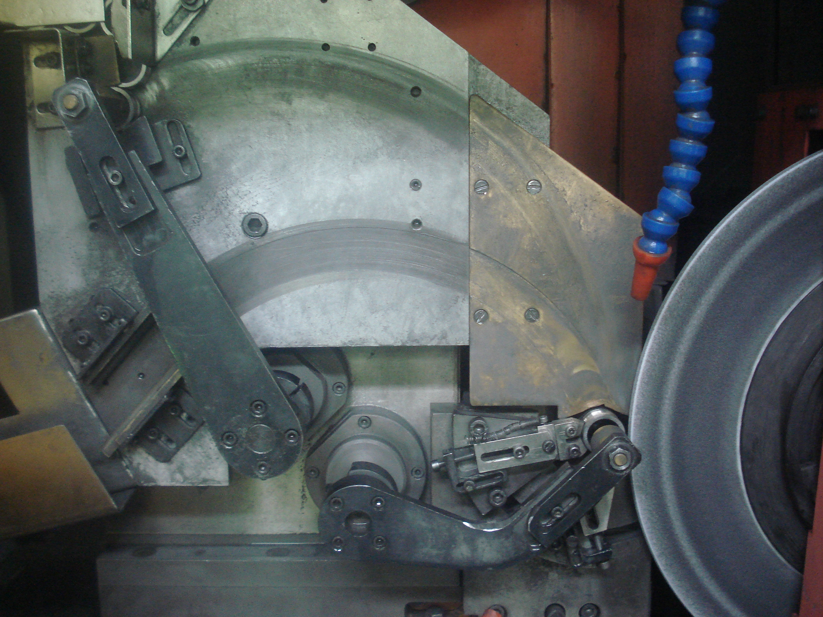
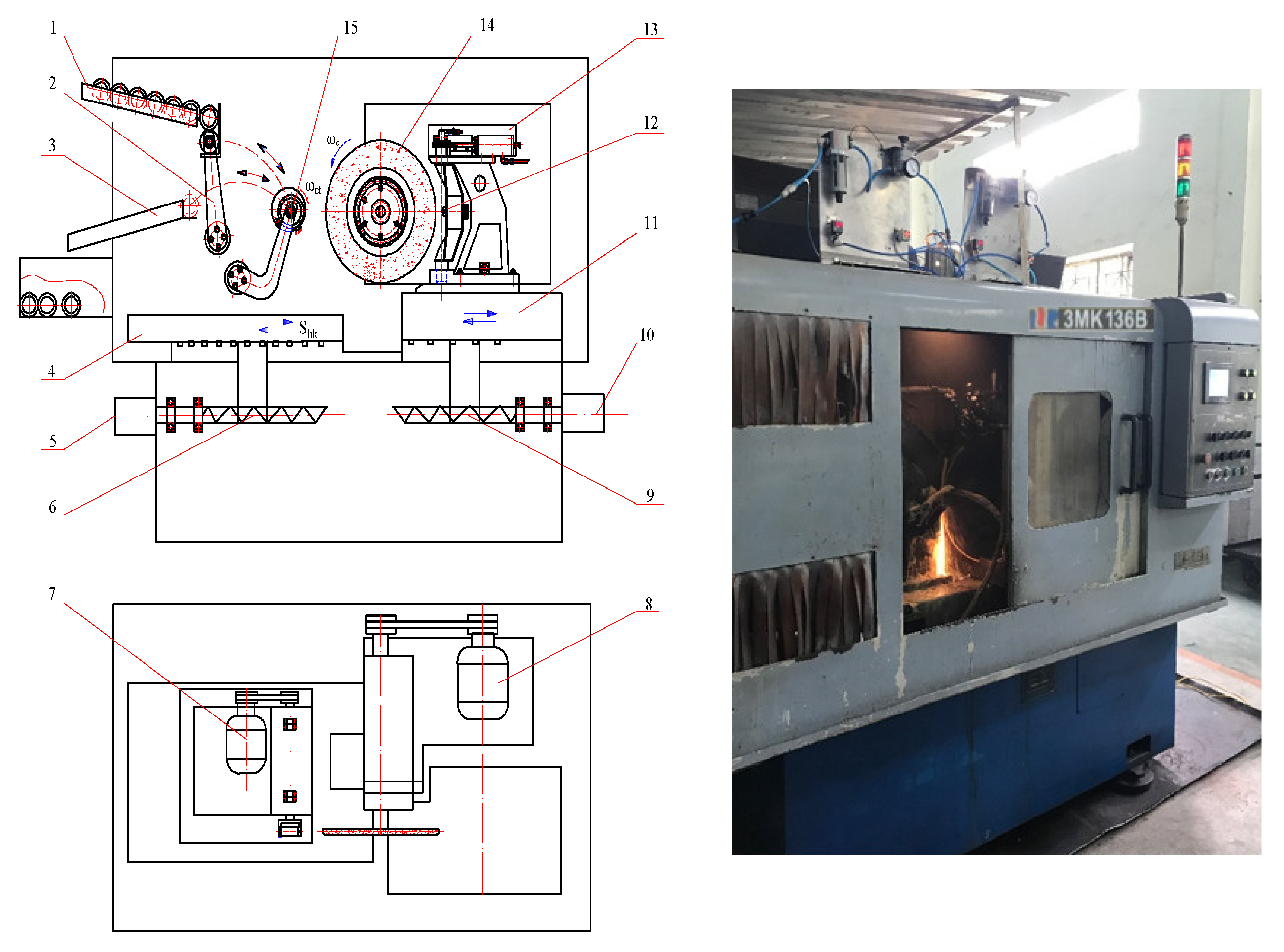
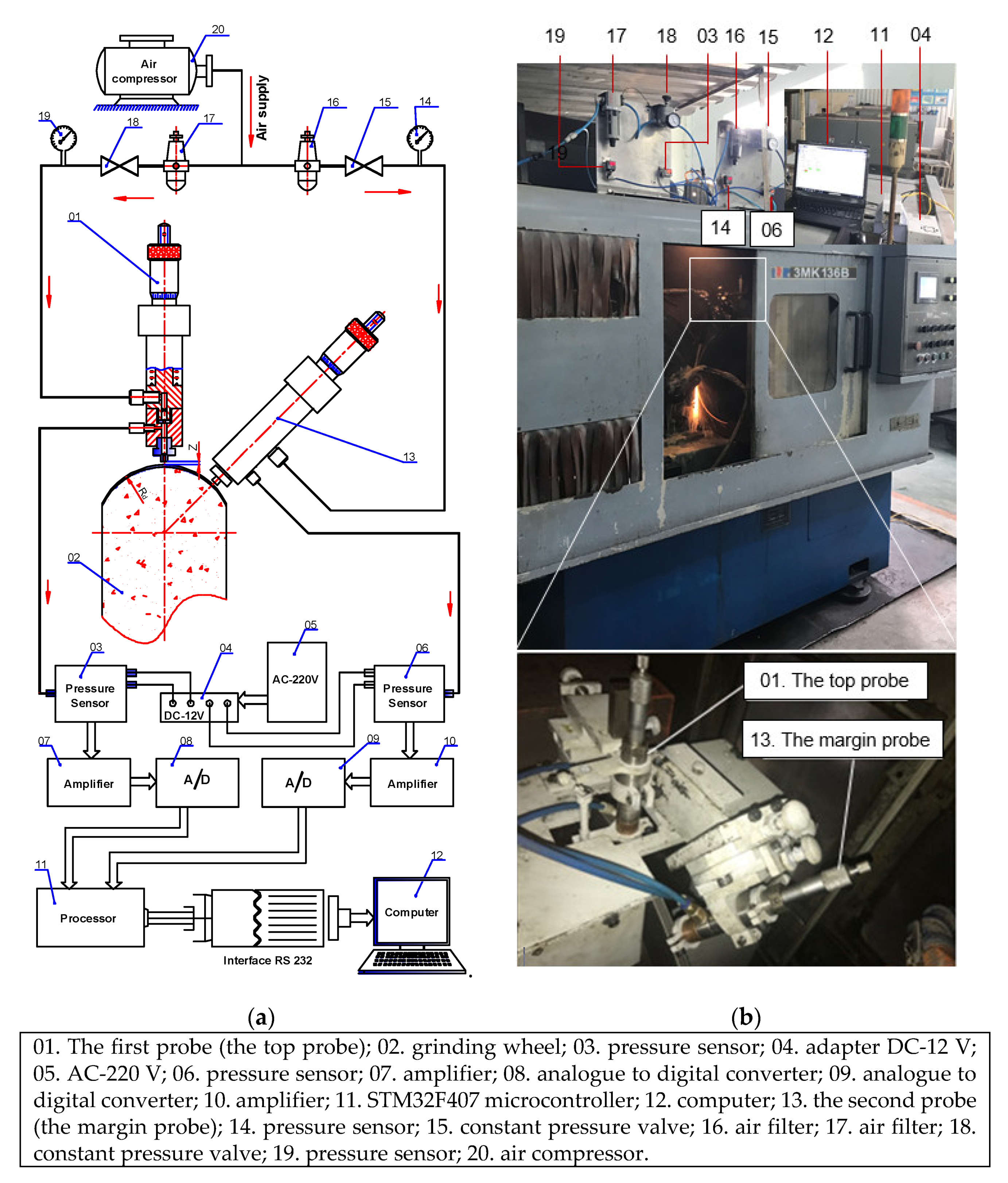
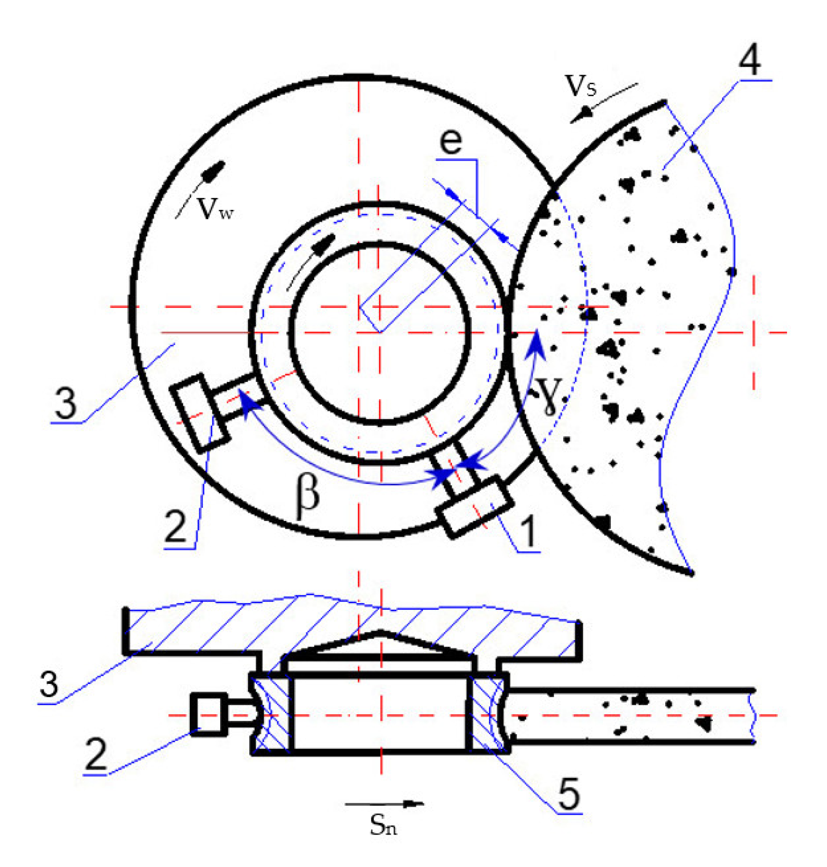
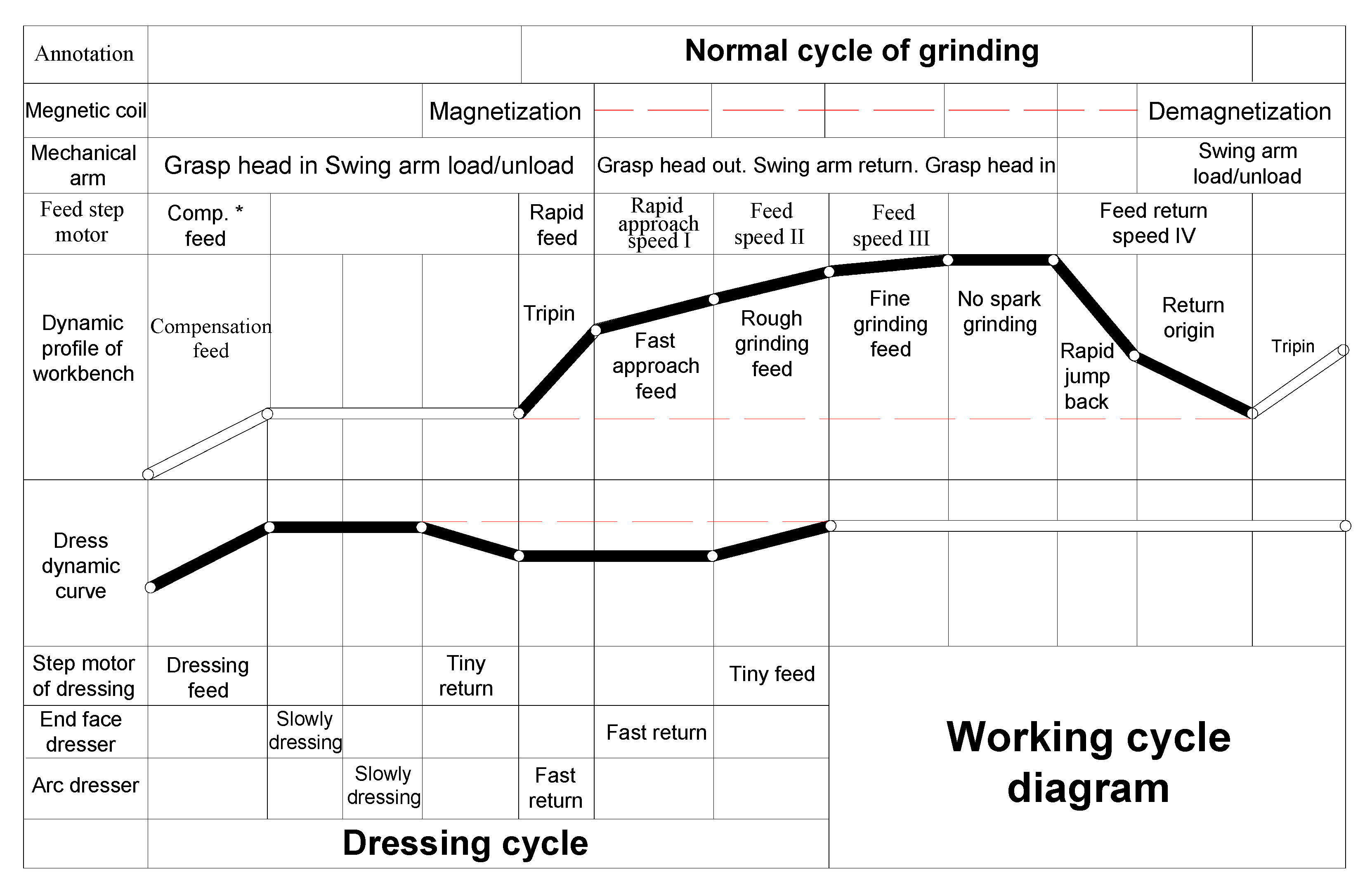
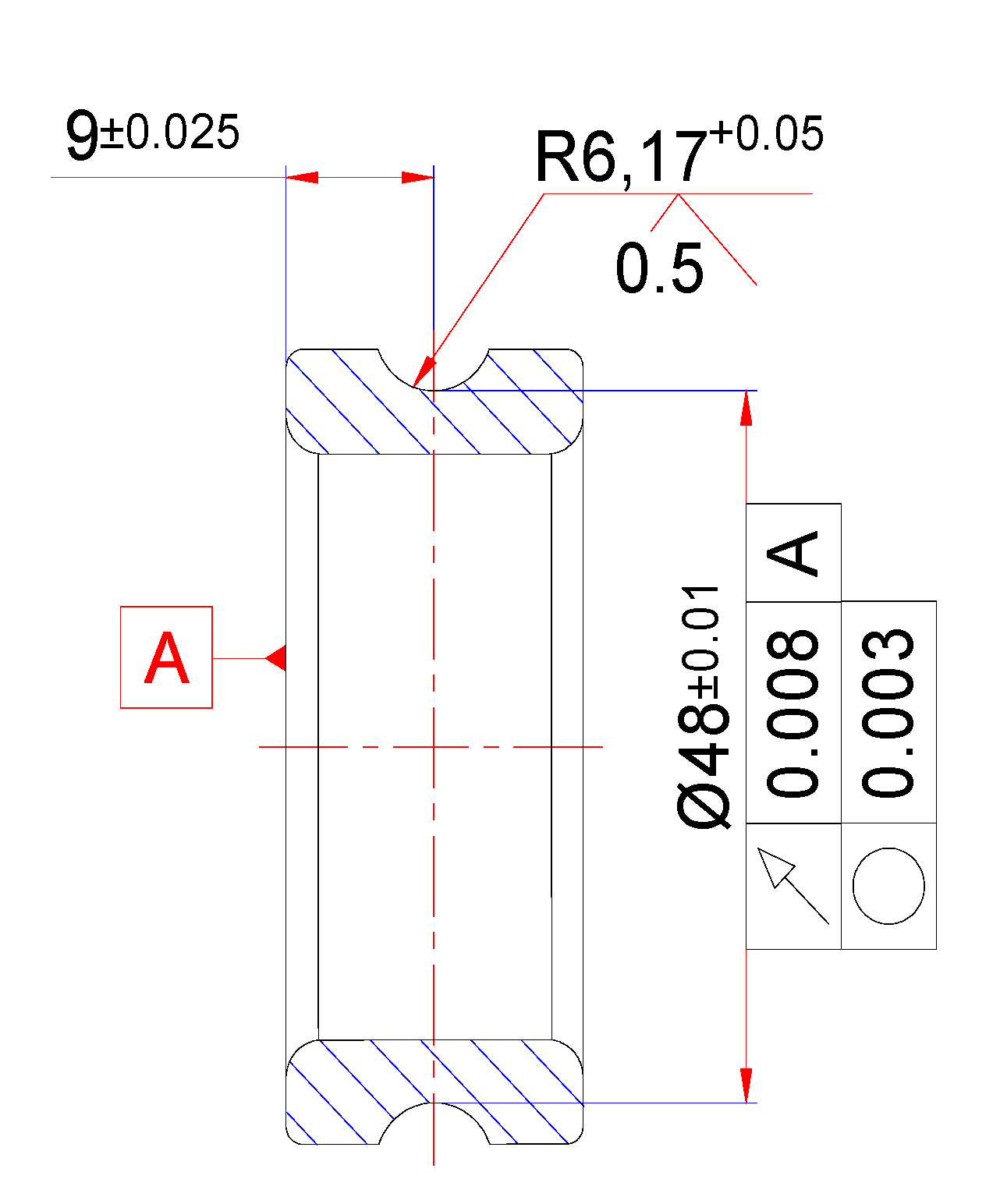
2.1. Test Specimen and Grinding Equipment

The aim of the experimental study was to determine the optimal set of process parameters in the shoe-type centerless grinding operation for the inner ring raceway surface, which allowed the smallest grindstone wear, the largest material removal rate, and the largest total number of ground parts in one grinding cycle, while the precision of ground parts was ensured.
The experiments were carried out on the 3MK136B bearing raceway grinder (made in China) equipped with the A100LV5 grinding wheel (made in China). This is a preferred machine used for grinding the inner ring raceway of ball bearing, applicable for batch auto production, with technical specifications as shown in Table 1. The specifications of the A100LV5 grinding wheels are shown in Table 2. The grinding wheel was dressed using a single-point diamond pen dresser. An emulsion was used as the grinding fluid. The inner ring of a model 6208_ball bearing consisting of SUJ2 alloy steel was used as the test specimen and subjected to a heat treatment prior to the grinding tests, followed by water quenching. The material of the ring was SUJ2 alloy steel (with an equivalent standard of JIS G4051). The chemical composition of SUJ2 alloy steel is shown in Table 3. The hardness of the workpiece after heat treatment varied between 62HRC and 65HRC (Rockwell hardness). The schematic diagram and realistic image of the processing equipment is shown in Figure 1.
The surface roughness of processed raceway was measured by a SJ400 roughness tester (made in Japan) as shown in Figure 2. The specifications of the SJ400 roughness tester are shown in Table 4.
The oval level of the raceway bottom diameter was measured by a D022 measurement equipment (made in China) with an accuracy of 1 μm, as shown in Figure 3. This equipment applies the comparative method to measure the oval of the raceway bottom diameter. Before measuring, it is necessary to select the standard sample bearing. In the measuring process, the first step is to press the lever of the bracket that is used to fix the raceway of bearing (no. 7) to take out the sample bearing. After that, the ball bearing’s inner ring (no. 3) is put in the measurement equipment. Then, the lever (no. 7) is released to let the pin (no. 4) fix the raceway’s position. Next, the raceway surface that needs to be measured will be located on two lock pins (no. 1 and no. 2). In this position, the ball bearing’s inner ring will be circled one round. The measuring meter (no. 5) indicates the maximum and minimum values of the raceway bottom’s diameter. The difference between these maximum and minimum values is its oval value. Meanwhile, the measuring meter (no. 6) indicates the maximum and minimum values of the distance from its raceway’s central line to its head surface. Based on that, the circular run-out of its raceway central line with its head surface is easily determined. Therefore, each measurement can simultaneously determine four tolerances including the raceway bottom diameter’s oval level, the circular run-out of its raceway central line to its head surface, the raceway bottom diameter’s dimension tolerance, and the dimension tolerance of the distance from its raceway central line to its head surface.
In this study, the wear value of the grinding wheel was measured by the measuring system consisting of two pneumatic probes, as shown in Figure 4. Two pneumatic probes were positioned at two different locations with the largest gap in the wear value on the curving edge surface of the grinding wheel. One measuring probe was mounted on the top of the curving edge surface and another at the margin of the curving edge surface of the profile grindstone on the 3MK136B grinder. Measuring the wear value of grindstone is an important part of this grinding process to determine the suitable dressing time. The wear can be determined by different measurement principles proposed in specific studies [18,19,20,21,22,23,24]. Some of them are based on capacitive [18] and acoustic emission principles [19]. Another method is based on the use of a CCD camera [20,21,22]. However, in addition to their high cost, those measurement methods have proved effective in library conditions but not for online measurement applications of precision grinding because of the negative influence of the grinding lubricant and the machining debris as well as eccentricity in wet grinding. Therefore, the pneumatic probes were used to measure the wear value of the grinding wheel in the study. This method allows online wear measurement in wet grinding condition and can overcome the difficulties of the mentioned methods [23,24]. In addition, this method provides some advantages including a simple design of the gauge, cost-effective maintenance, as well as an easy adjusting sensitivity and measuring range. Thus, grindstone wear in this study was measured by our measuring system consisting of two pneumatic probes (made in Vietnam). The top pneumatic probe has a measurement range of 200 μm with an accuracy of 1 μm, whereas the margin pneumatic probe has a measurement range of 140 μm with an accuracy of 1 μm [23]. The design of the probes as well as the solution for signals acquisition and processing in these probes are presented in [23].

2.2. The Determination of Process Parameters and Characteristic Responses for Optimization

Figure 5 shows the principle of the shoe-type centerless grinding process for the bearings’ inner ring raceway. In the machining process, the workpiece was positioned on two fixed ring supports with mounting angles of the two supports as β and ɣ. The surface of inner ring raceway and the head surface of the inner ring were used as the positioning standard to minimize the mounting error and to assure the correlative position between the groove central line and the head surface. The grinding process was proceeded by the normal motions of the machine including the rotation motion of the workpiece (Vw), the rotation motion of the grinding wheel (VS), and the normal feed motion of the workbench (Sn).
Therefore, the process parameters in the shoe-type centerless grinding operation for the inner ring raceway on the 3MK136B grinder included the wheel speed (VS), the workpiece speed (VW), the normal feed rate of rough grinding (Snr), the normal feed rate of fine grinding (Snf), the depth of rough grinding (ar), the depth of fine grinding (af), the number of ground parts (Np), and the mounting angle of the two ring supports (β, γ). However, for grinding on a CNC grinder with a specific grinding wheel, the wheel speed is usually chosen according to the specifications of the grinding wheel that have been given by the manufacturer. For example, the grinding wheel of A100L5V has a wheel speed (VS) of 60 m/s. In addition, the optimal mounting angle of the two ring supports was determined by O.B. 3ахаров [15]. In addition, the cutting regime for rough grinding has an insignificant effect on the quality of the ground parts. Thus, this study considered only process parameters for fine grinding to evaluate its influence on the machining accuracy, grinding wheel wear, and the material removal rate. As a result, the four process parameters including the normal feed rate of fine grinding (Snf), the workpiece speed (Vw), the depth of fine grinding (af), and the number of ground parts (Np) were investigated in this study.
Figure 6 shows the working cycle diagram of the 3MK136B bearing raceway grinder. The machine can automatically process according to the preset grinding cycle at the initial time. When the machine is automatically performing the grinding cycle, as per the preset dressing interval, the control system will automatically stop the grinding cycle and shift into the dressing cycle. Specifically, based on counting the number of motion movements of the workbench, the number of ground parts (Np) is determined automatically by the control system of the machine. Then, based on the preset total number of ground parts in one grinding cycle (N’p) at the initial time, the dressing time is determined automatically by the control system of the 3MK136B bearing raceway grinder. The machine will dress the grinding wheel when the number of ground parts, which is determined by the control system during the machining process (Np), is equal to the total number of ground parts in one cycle (N’p), which is installed at the initial time before machining. Thus, the total number of ground parts in one cycle installed at the initial time is equal to the last number of ground parts determined by the machine’s control system at the dressing timing. At the time that the last number of ground parts is at a maximum, the total number of ground parts in one cycle is also the largest. Simultaneously, the maximum value of the total number of ground parts in one cycle is equal to the maximum value of the number of ground parts. Thus, the number of ground parts (Np) is an important process parameter of the 3MK136B grinder, which characterizes the grinding time factor, as a basis for the machine’s control system to automatically determine the dressing time. This is especially true if the total number of ground parts in one cycle (N’p) is considered as an objective function of the optimization problem with the desire to be as large as possible to reduce the waste of the grinding wheel and increase productivity. The objective function can be determined through the number of ground parts (Np) as follows:
N’p = f (Np) = Np
To process the raceway surface, it requires not only dimensional accuracy for the raceway bottom’s diameter, the raceway’s radius, and distance from the raceway central line to the head surface but also the accuracy for correlative positions including the oval level of the raceway bottom’s diameter and the circular run-out of the raceway central line in comparison to the head surface. In particular, the surface roughness of the raceway must be smaller than 0.5 µm (Ra < 0.5 µm), and the oval level of the raceway bottom’s diameter must be smaller than 3 µm (Op < 3 µm) [25]. These technical requirements of the finish grinding operation for the 6208_ball bearing’s inner ring raceway with precision level P06 are shown as Figure 7. However, the experimental data also showed that, with different values of the input parameters in the setting ranges, the quality requirements of the dimension deviation of the groove diameter, the dimension deviation of the distance from the groove’s center line to head surface, the dimension deviation of the groove radius, and the circular run-out of the groove central line to the head surface were still satisfied [15]. It can be explained that, for example, the dimension deviation of the distance from the groove’s center line to the head surface depends mainly on the fixing position of the workpiece but insignificantly on the input setting parameters. Thus, in that sense, only the dependencies of the performance factors, which were the grindstone’s wear, the part’s oval level, and the part’s surface roughness on input setting factors, which included the normal feed rate of fine grinding (Snf), the workpiece speed (Vw), the depth of fine grinding (af), and the number of ground parts (Np), were taken into account.
In order to solve such an optimization problem, it was necessary to determine the dependencies of the performance factors, which were the grindstone’s wear (Gw), the part’s oval (Op), the part’s surface roughness (Ra), and the material removal rate (MRR) on process parameters, which were the normal feed rate of fine grinding (Snf), the speed of the workpiece (Vw), the depth of fine grinding (af), and the number of ground parts (Np). Thus, experimental data is necessary in order to determine their mathematical models.

2.3. Design of Experiments and Experimental Results

The values of input parameters in this study were chosen based on the manufacturing technology manual of a 3MK136B bearing raceway grinder. The assigned values of input parameters at different levels and their designation are tabulated in Table 5. The values of other parameters were kept constant throughout the experiment.
In order to fully consider all these factors affecting the efficiency in the shoe-type centerless grinding operation for the inner ring raceway surface, 81 (34) experiments were conducted. In addition, each experimental run was performed three times to ensure the accuracy of the regression function. The average output values of all three experiments corresponding to each set of technology modes were used to determine the experimental regression function. The sequence of steps to determine the value of output responses in each experiment was as follows:
-
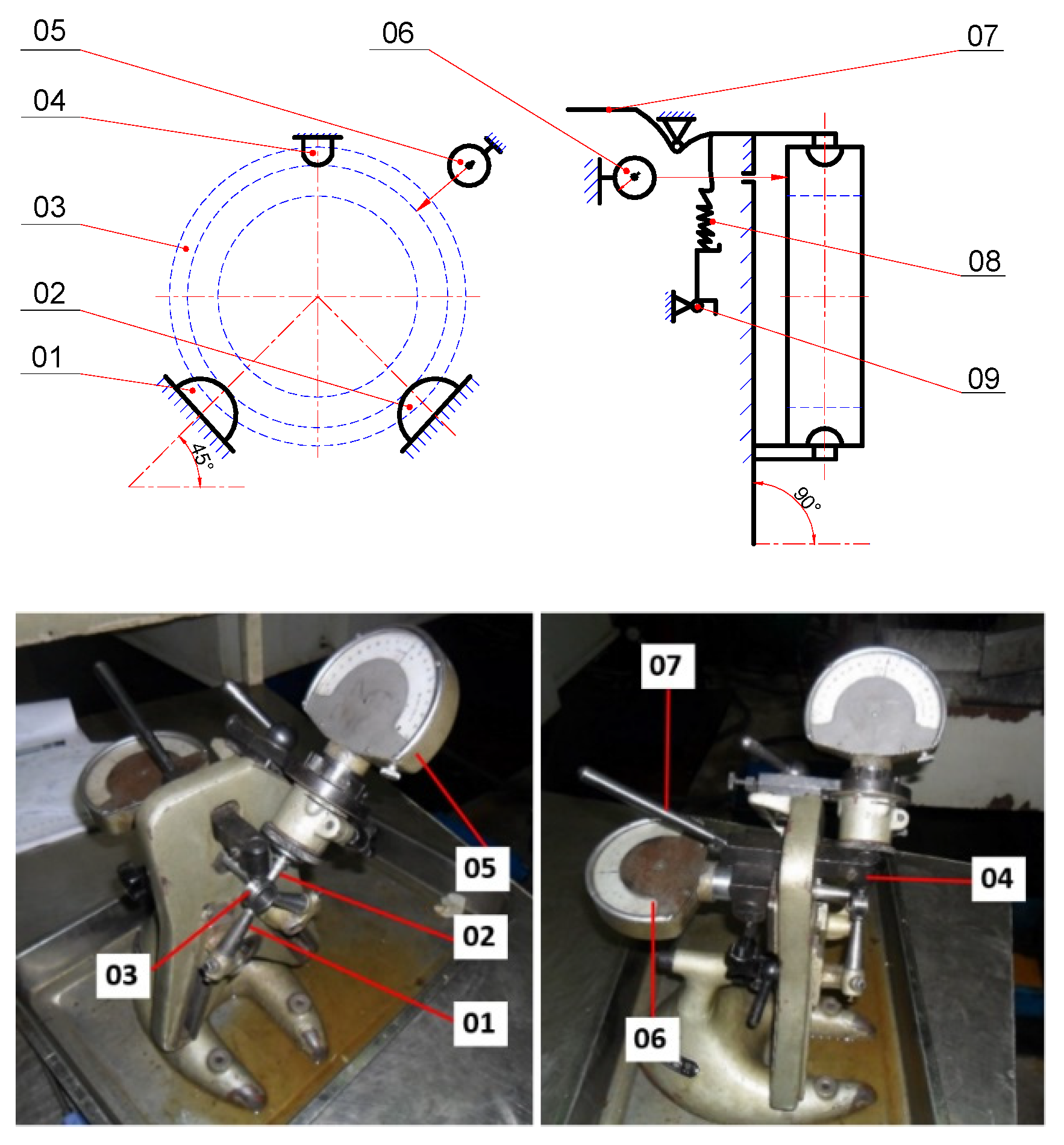
The first step: measuring the wear value of the grinding wheel after each test by using the pneumatic measuring system.
-
The second step: measuring the oval level of the raceway bottom diameter after each test by using the D022 measurement equipment.
-
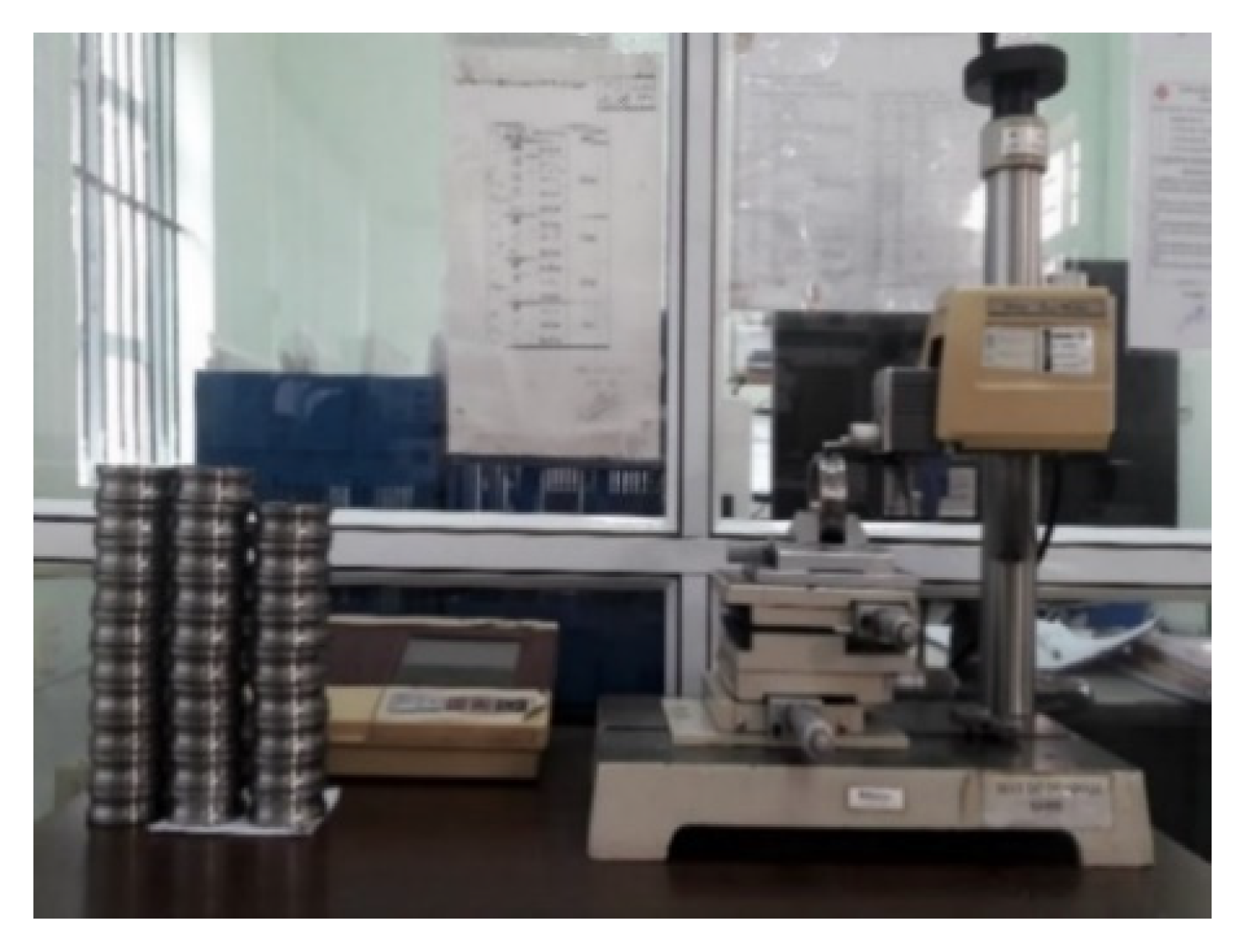
The third step: measuring the surface roughness of the processed raceway after each test by using the SJ400 roughness tester.
-
The fourth step: determining the value of the material removal rate (MRR) after each test. The value of the material removal rate (MRR) was determined by Equation (2) [26,27].
MRR = w b w a T m ( g / min )
where:
  • Wb: workpiece weight before processing (g). It was measured using weight balancing.
  • Wa: workpiece weight after processing (g). It was measured using weight balancing.
  • Tm: machining time (s).
The obtained results of the experiments are presented as in Table 6.
The experimental results were the basis to analyze the influence of process parameters on the efficiency of the inner ring raceway surface grinding process.

3. Establishing Mathematical Models for Main Output Parameters over Process Parameters

The input variables in empirical regression models are often selected based on empirical information and theoretical research results. However, this is only the initial orientation information. Thus, exploration experiments should be conducted to verify the theoretical basis before conducting a comprehensive experiment to build accurately the experimental regression functions. Therefore, exploration experiments in this study were carried out.
The results of the exploration experiments showed that the grinding wheel was unevenly worn at various points on the curving edge surface of the grinding wheel. The wear value at the edge of the curving edge surface of the grinding wheel was usually bigger than that at the top of the curving edge surface of the grinding wheel. This was possibly caused by the unevenly distributed mechanical allowance. The mechanical surplus at the edge of the profile was bigger than that at the top of the profile. This caused the uneven wear. Thus, the wear value at the edge of the curving edge surface of the grinding wheel was used to evaluate the impact of technology mode on grinding wheel wear and the accuracy of the part. In addition, it was also found that the material removal rate in this grinding process depended only on the normal feed rate of fine grinding (Snf) and the depth of fine grinding (af) among the four selected process parameters. Based on that, the dependencies of performance factors such as the grindstone’s wear, the part’s oval level, and the part’s surface roughness on process parameters including the normal feed rate of fine grinding (Snf), the speed of the workpiece (Vpw), the depth of fine grinding (tf), and the number of ground parts (Np) were studied by analyzing diagrams for the distribution of the part’s accuracy tolerance zone and the grindstone wear according to the number of ground parts. One of such diagrams is illustrated in Figure 8.
From the above diagrams, some findings can be presented as follows:
-
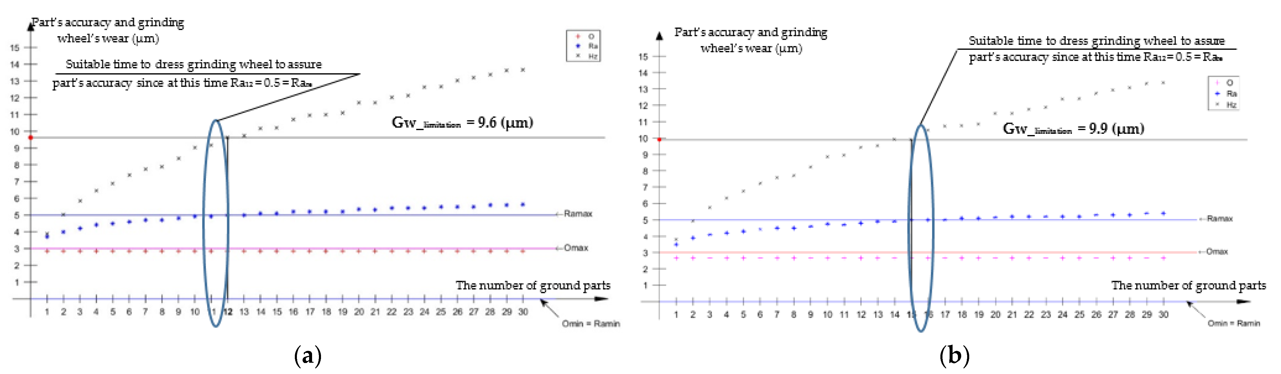
For a certain set of process parameters, when the number of ground parts increased, the wear of the grinding wheel and the surface roughness of the raceway also increased, but the oval level of the raceway bottom’s diameter did not change. Therefore, according to grinding time, there is a moment at which the accuracy of the ground part will exceed the required accuracy. For the first set of process parameters, when the 12th part was ground, its surface roughness of the raceway was equal to the required surface roughness value (Ra12 = Rare = 0.5 μm). For this reason, from the 12th part upward, the surface roughness was not guaranteed as the requirement. This was the appropriate time to dress the grinding wheel. Thus, the wear value at the 12th part is the economic limitation wear value of the grinding wheel corresponding to the above cutting mode. Therefore, for the first set of process parameters, the economic limitation wear value was equal to the wear value at the 12th part, i.e., Gw_limitaiton = Gw12 = 9.6 μm.
-
For different sets of process parameters, the economic limitation wear values of the grinding wheel were different. For example, for the cutting mode of Snf = 12.5 µm/s, Vw = 12 m/min, and af = 15 µm, it was shown that when the 12th part was ground, its surface roughness was exactly the same as the standard surface roughness value (Ra12 = 0.5 µm = Rare). Thus, for this cutting mode, it showed that Gw_limitation = Gw12 = 9.6 µm. For the cutting mode of Snf = 12.5 µm/s, Vw = 12 m/min, and tf = 10 µm, the part’s surface roughness value reached the standard surface roughness value at the 15th part (Ra15 = 0.5 µm = Rare), i.e., Gw_limitation = Gw15 = 10.26 µm.
-
When the parameters of the cutting mode (Snf, Vw, af) changed, the grinding wheel’s wear value (Gw1, Gw2, etc.), the part’s surface roughness (Ra1, Ra2, etc.), and the oval level of the raceway bottom’s diameter (O1, O2, etc.) also changed. For the first set of cutting mode parameters (Figure 8a), those values after grinding the first part, the second part, the third part, and the fourth part were Gw1 = 3.65 µm, Gw2 = 4.71 µm, Gw3 = 5.50 µm, Gw4 = 6.05 µm, Ra1 = 0.33 µm, Ra2 = 0.36 µm, Ra3 = 0.38 µm, Ra4 = 0.39 µm, O1 = O2 = O3 = 2.67 µm, and O4 = 2.83 µm, respectively. For the second set of cutting mode parameters (Figure 8b), those values after grinding the first part, the second part, the third part, and the fourth part were Gw1 = 3.89 µm, Gw2 = 5.03 µm, Gw3 = 5.88 µm, Gw4 = 6.48 µm, Ra1 = 0.37 µm, Ra2 = 0.40 µm, Ra3 = 0.42 µm, Ra4 = 0.44 µm, O1 =1.83 µm, and O2 = O3 = O4 = 2.33 µm, respectively. Thus, the process parameters including the normal feed rate of fine grinding (Snf), the speed of the workpiece (Vw), the cutting depth of fine grinding (af), and the number of ground parts (Np) influenced the grinding wheel’s wear, the raceway’s surface roughness, and the oval level of the raceway bottom’s diameter.
Based on the above analysis results as well as mathematical models of previous studies [3,28], the output factors (Ra, Hz, O, MRR) can be hypothesized as products of exponents of the input variables (Snf, Vw, af, Np).
Ra = a 01 · S n f a 1 · V w a 2 · a f a 3 · N p a 4
G w = b 01 · S n f b 1 · V w b 2 · a f b 3 · N p b 4
O p = c 01 · S n f c 1 · V w c 2 · a f c 3
MRR = d 01 S n f d 1 a f d 3
Linearizing the above nonlinear equation by the logarithm of both sides of the above equations, we obtained:
Ln ( Ra ) = Ln ( a 01 ) + a 1 ln ( S n f ) + a 2 ln ( V w ) + a 3 ln ( a f ) + a 4 ln ( N p )
Ln ( G w ) = Ln ( b 01 ) + b 1 ln ( S n f ) + b 2 ln ( V w ) + b 3 ln ( a f ) + b 4 ln ( N p )
Ln ( O p ) = Ln ( c 01 ) + c 1 ln ( S n f ) + c 2 ln ( V w ) + c 3 ln ( a f )
Ln ( MRR ) = Ln ( d 01 ) + d 1 ln ( S n f ) + d 3 ln ( a f )
Define:
y1 = Ln(Ra); a0 = Ln(a01);
y2 = Ln(Gw); b0 = Ln(b01);
y3 = Ln(Op); c0 = Ln(c01);
y4 = Ln(MRR); d0 = Ln(d01);
x1 = ln(Snf); x2 = ln(Vw); x3 = ln(af); x4 = ln(Np)
Thus: y1 = a0 + a1x1 + a2x2 + a3x3 + a4x4
y2 = b0 + b1x1 + b2x2 + b3x3 + b4x4
y3 = c0 + c1x1 + c2x2 + c3x3
y4 = d0 + d1x1 + d3x3
Therefore, the first-order model was used to represent the mathematical relationship between input parameters and output responses in this study. The coefficients of those models (ai, bi, ci, di) were defined by applying the regression approach with the least-square method. The significance level was set to 0.02, and the confidence level was set to 95%. Based on 81 sets of experimental results (as shown in Table 5), the regression analysis was done by using the MATLAB software. The obvious function expressions of these models were obtained as follows.
-
Mathematical model for the surface roughness of parts:
Ra = 0.163   S n f 0.1224 V w 0.10002 a f 0.1005 N p 0.1194
-
Mathematical model for the grindstone wear:
G w = 2.1688   S n f 0.0965 V w 0.0657 a f 0.0557 N p 0.3772
-
Mathematical model for the oval level of parts:
O p = 1.14498 S n f 0.19996 V w 0.1127 a f 0.1966
-
Mathematical model for the material removal rate:
MRR = 0 . 1616 S n f 0.2418 a f 0.15085
The regression statistics of the developed mathematical models are shown in Table 7. The values of R2 (0.9978 for the surface roughness model, 0.9996 for the grinding wheel wear model, 0.8685 for the oval level model, and 0.9896 for the material removal rate model) in Table 7 indicate that the four models (Equations (15)–(18)) were well fitted with experimental data. It also implies that the surface roughness model (Equation (15)), the grinding wheel wear model (Equation (16)), the oval level model (Equation (17)), and the material removal rate model (Equation (18)) explain 99.78%, 99.96%, 86.85%, and 98.96% of the variability of the grinding wheel wear, the surface roughness, the oval level, and the material removal rate, respectively. Adjusted R2 values of the surface roughness model, the grinding wheel wear model, the oval level model, and the material removal rate level are also shown in same table; these were 0.9977 (99.77%), 0.9995 (99.95%), 0.8634 (86.34%), and 0.9862 (98.62%), respectively, indicating good correlations.
Standard error (θ) and the dispersion (σ) indicate the predictive ability of the model. If the value of any model is small, the corresponding model possesses greater predictive ability. From the values of standard error and dispersion (Table 7), it is shown that the four models have the ability to predict the optimum grinding condition.
Based on the above mathematical functions, some findings can be presented as follows:
-
When the normal feed rate of fine grinding (Snf) increased, the material removal rate (MRR), the grinding wheel wear (Gw), and the surface roughness (Ra) increased. When the workpiece speed (Vw) increased, the grinding wheel wear (Gw) and the surface roughness (Ra) also increased. However, the degree of influence of the workpiece speed on the grinding wheel wear and the surface roughness was lower than those of the normal feed rate. When the depth of cutting (a) increased, the material removal rate (MRR), the grinding wheel wear (Gw), and the surface roughness (Ra) increased. However, the increase in grinding wheel wear and surface roughness was negligible. In this case, the cause was mainly due to the influences of vibration, the cutting force, and grinding wheel wear. When the normal feed rate of fine grinding (Snf) or the workpiece speed (Vw) increased, the cutting force and the cutting heat increased. This led to the increase in the grinding wheel wear and the surface roughness. However, in the case of the oval level (Op), the influence of workpiece speed on the oval level was reversed. When workpiece speed (Vw) increased, the oval level (Op) decreased, and vice-versa. In this case, the cause was mainly due to the uneven distribution of metal removal over the whole workpiece circumference. The nature of workpiece rotation is the motion of feed per revolution. When the speed of the workpiece (Vw) reduced, the values of the cutting depth per rotation increased. Thus, the distribution of the surplus stock over the whole workpiece circumference could be uneven. For example, in the case of the workpiece speed (Vw) of 6 m/min (100 mm/s) and the workpiece diameter (D) of 48 mm, the number of workpiece revolutions per second was determined as follows:
n w = 100 π . D = 100 π .48 0.66 ( s 1 )
Therefore, in one second, the workpiece rotated 0.66 revolutions. If the normal feed rate (Sn) is equal to 5 µm/s, in one second, the workbench will be cut into 5 µm. Hence, in the 1st second, the grinding wheel cuts into the workpiece surface the same amount of metal removed as the amount of the normal feed rate (5 µm). However, in the 2nd second, since the rotation of the workpiece has not yet reached its full circle, the grinding wheel must cut into the workpiece surface the amount of metal removed that is twice the amount of the normal feed rate (10 µm). Thus, the amount of metal removal over the entire perimeter of the workpiece will be unevenly distributed throughout the grinding process. As a result, on the whole perimeter of the workpiece, there are some positions that grindstone will cut with a large metal removal, and there are some positions that the grindstone will cut with a smaller metal removal. Thus, the diameter deviation of the ground part at different cross sections will be increased. This leads to an increase in the part’s oval level. Similarly, the value of the diameter deviation also depends on the normal feed rate of fine grinding (Snf). If the normal feed rate of fine grinding (Snf) increases, the values of cutting depth per rotation will increase. Thus, the part’s oval level (Op) will also increase as well, and vice-versa. In addition, the part’s oval level (Op) also depends on the cutting depth (a). When the depth of fine grinding (af) increases, the amount of metal removed and the uneven distribution of metal removal over the whole workpiece circumference during the grinding process will also increase. Therefore, this leads to an increase in the part’s oval level.
-
When the number of ground parts (Np) increases, the part’s surface roughness (Ra) and the grinding wheel’s wear (Gw) will also increase. In particular, the impact of the number of ground parts (Np) on the surface roughness of parts (Ra) and the wear of the grinding wheel (Gw) is much greater than the effect of the normal feed rate (Sn), the workpiece speed (Vw), and the depth of fine grinding (af). However, the number of ground parts (Np) does not affect the part’s oval (Op). In this case, the cause is mainly due to the influences of grinding wheel wear. In the machining process on the 3MK136B grinder, the grindstone dresses are only implemented at the end of a grinding cycle. Thus, the wear of the grinding wheel (Gw) increases when the number of ground parts (Np) increases. This leads to an increase in the surface roughness of parts. However, it does not affect the diameter deviation of ground parts at different cross sections. Thus, the oval level of parts does not change when the number of ground parts increases.

4. Multi-Objective Optimization

4.1. Establishing Constraints

In the bearing inner ring raceway grinding process, constraints can be divided into two types.
Because of the limitations of the 3MK136B grinder and the grinding wheels, the constraints for the process parameters are defined as follows:
5   ( μ m / s )   S n f   20   ( μ m / s ) 6   ( m / min )   V w   18   ( m / min ) 10   ( μ m )   a f     2 0   ( μ m ) 1   ( part )   N p  
Particularly, it is noticeable that parameter Np, the number of ground parts, must be a positive integer.
Because of the requirements of product quality (as shown in Figure 7), the constraints for product quality are defined as follows:
Ra 0.5 ( μ m ) O p 3 ( μ m )
Therefore, according to the mathematical models, which were established in Section 3, and the above-mentioned constraints, the variable space for input parameters Fnf, Vp, tf, and Np was defined. Particularly, since the mathematical models of Ra and Op are presented as products of exponents of input parameters, the variable space can be simplified by regarding the logarithm values of input parameters rather than the values themselves. The target function of the optimization problem, thereafter, would also be established through those logarithm variables.
Substituting (15) and (17) into (21), the constraints for product quality are rewritten as follows:
log ( Ra ) = log 0.163 + 0.1224 log ( S n f ) + 0.10002 log ( V w ) + 0.1005 log ( a f ) + 0.1194 log ( N p ) log 0.5 log ( O p ) = log 1.14498 + 0.19996 log ( S n f ) 0.1127 log ( V w ) + 0.1966 log ( a f ) log 3
Thus, the constraints are rewritten as:
log ( Ra ) = log 0.163 + 0.1224 log ( S n f ) + 0.10002 log ( V w ) + 0.1005 log ( a f ) + 0.1194 log ( N p ) log 0.5 log ( O p ) = log 1.14498 + 0.19996 log ( S n f ) 0.1127 log ( V w ) + 0.1966 log ( a f ) log 3 log 5 log ( S n f ) log 20 log 6 log ( V w ) log 18 log 10 log ( a f ) log 20
where: logX presents the logarithm value of a positive variable X. Notice that the set value of logNp is discrete.

4.2. Establishing the Objective Function

In production, it is always expected that the wear value of the grinding wheel can be minimized and that the material removal rate and the total number of ground parts in one grinding cycle can be maximized, while the precision of ground parts remains ensured. This is to ensure that the length of the dressing time and the waste of the dresser and the grinding wheel can be minimized, while the durability of the grinding wheel and the productivity of the grinding process can be maximized. Thus, the target function is a multi-objective function of the grinding wheel wear, the material removal rate, and the total number of ground parts in one grinding cycle. Therefore, a multi-objective function with a weighted approach for optimization of the inner ring raceway grinding process was adopted. As mentioned before, the objective function can be constructed through the new logarithm variables. The combined weighted objective function to be minimized here is as follows [5,12]:
f = 0.4logGw − 0.2logN’p − 0.4logMRR → min
Substituting (1), (16), and (18) into (23), the objective function is rewritten as:
f = 0.4(log (2.1688) − log (0.1616)) − 0.05812.log (Snf) + 0.02628.log (Vw) − 0.03806.log(af) − 0.04912.log (Np)

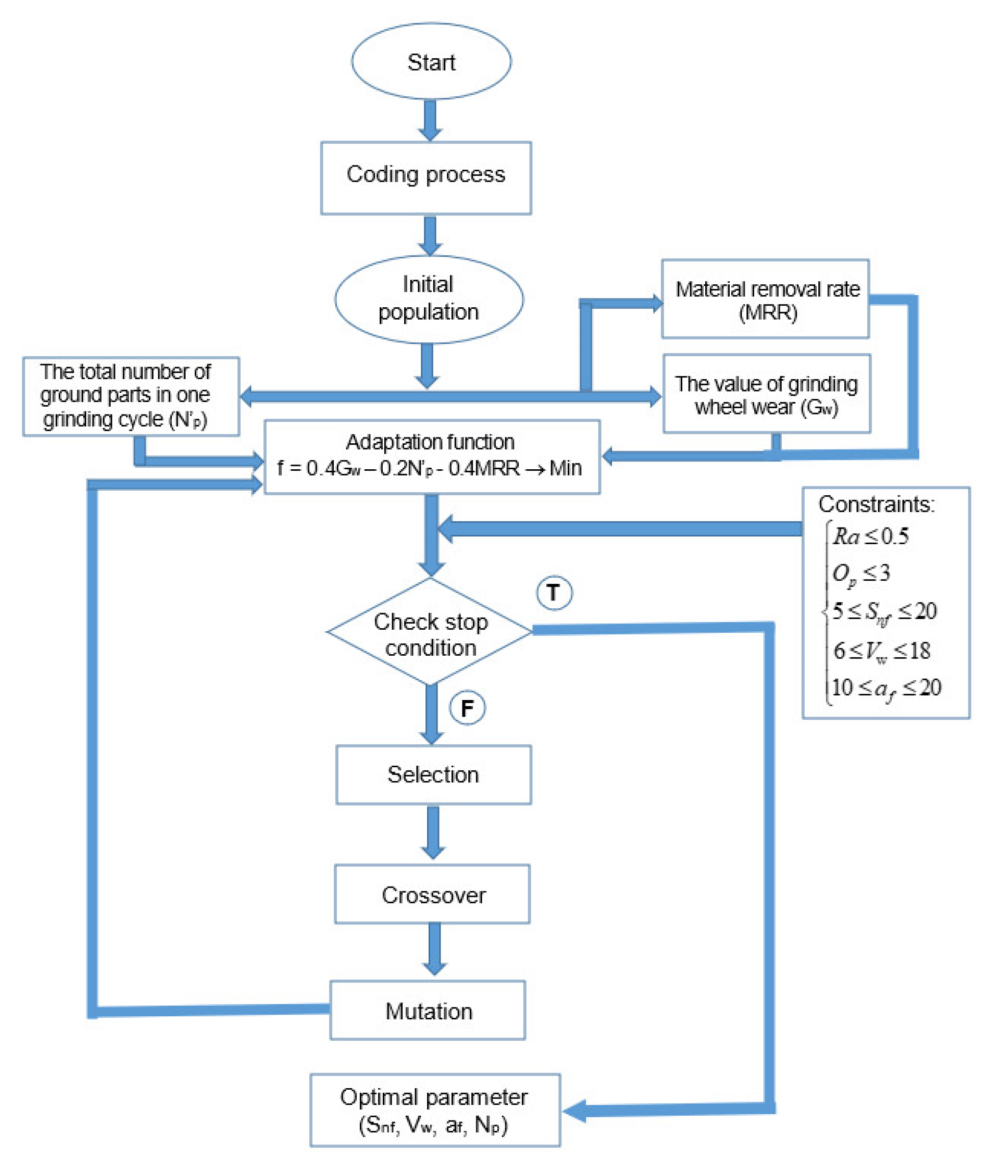
4.3. Applying a Genetic Algorithm (GA) to Solve the Optimization Problem

As the constraints and target function are established in such a way as (23) and (25), the optimization problem is “almost” linear, except the condition for the variable log (Np) is discrete. Besides, the objective function can be constructed in many different ways that easily make the optimization problem non-linear. Therefore, the optimization problem for the raceway surface grinding operation can be considered as a multi-objective, multi-variable, non-linear optimization problem with multi-constraints. As a result, traditional linear methods would not be effective in order to solve such a problem.
To solve the multi-objective optimization problem of the grinding process, various techniques have been used so far. Traditional techniques such as geometric methods, quadratic programming methods, etc. are difficult to solve these problems, and they tend to reach a locally optimal solution. Thus, based on the application of artificial intelligence (AI), some non-traditional methods such as genetic algorithms, artificial bee colony (ABC) algorithms, etc. have been applied to optimize process parameters in the grinding operation. Each of these methods has their unique advantages and disadvantages. The GA has outstanding advantages such as ease of use, finding global optimal solutions with high probability, and efficiency in solving multi-objective optimization problems. The GA has disadvantages such as less convergence speed and difficulty in choosing the parameters such as population size, crossover rate, and mutation rate, but these problems can be overcome by the user’s experience.
In this study, to overcome the mentioned difficulties, an approach to the solution for the multi-objective optimization problem by using a genetic algorithm was applied. The genetic algorithm, the same as in general evolutionary terms, was developed based on the idea that natural evolution is a perfect and appropriate process as well as a preeminent one [3,5]. This method is different from other traditional methods in several features [3,5]:
-
The GA solves the optimization problem by encrypting setting parameters instead of using such parameters to solve.
-
The GA searches from a population of individuals instead of each individual.
-
The GA uses adaptation functions’ information without derivation or addition of other knowledge to evaluate the target function to support the search process. Therefore, GAs can be applied to most optimization problems (continuous or discrete).
-
The GA uses a transitive probability rule (transitivity) instead of a random rule.
The GA is a computing science technique to find out the most suitable solution for a combinatorial optimization problem [3,5]. The technique uses the computing language to illustrate the evolutionary process of a collection of abstract representatives (called chromosomes) of possible measures (called individuals) for the optimization problem. The initial collection of solutions goes through evolutionary steps to form newer and more appropriate solution collections and finally leads to the global optimization solution [3,5]. The GA illustrates four basic processes: crossover, mutation, natural reproduction, and selection [3,5].
In this study, to solve the optimization problem with the constraints (23) and the objective function (25), a program applying the GA with the support of the MATLAB Global-Optimization Toolbox was developed. The algorithm diagram for the GA software program to solve the optimization problem of technology parameters in the centerless profile grinding operation for the inner ring groove’s surface of the 6208_ball bearing is illustrated in Figure 9.
It can be seen from above block diagram that the genetic algorithm was carried out in basic steps as follows:
-
The coding process: in order to solve this optimization problem using the GA, binary coding was used to represent the variables Snf, Vw, af, and Np. This coding process aimed to represent the chromosomes that contain information for the solution. In the calculation here, 10 bits were chosen for Snf and 7 bits for the other variables, thereby generating the total length to 31.
-
Generating the initial population: after selecting the appropriate coding method, input variables were encoded into chromosomes. This collection of chromosomes will form a population. The generation can begin with a population consisting of randomly generated individuals within the upper and lower limitation range of the variable.
-
Calculating the adaptation value and evaluating the constraints: after initializing the population, the output values (Gw, Ra, Op, MRR, N’p) are determined. Based on that, the target function value is determined, and the constraints are checked. This is the basis for suitable parental selection of crossover and mutation processes.
-
The selection process: selection aims to eliminate bad individuals in a population and keep good ones. Based on the target function value, in each generation, individuals with good adaptability are selected to form a new generation and prepare for implementation of the next crossover and mutation. In this study, the roulette wheel selection method was used for reproduction. The probability of choosing an individual for breeding for the next generation was proportional to its fitness; the better the fitness, the higher the chance for that individual to be chosen. The probability of choosing an individual {pi} was equal to:
p i = f i Σ i = 1 N f i
where:
fi is the fitness of i.
N is the size of the current generation.
-
The crossover process: this process creates the offspring chromosomes on the basis of selected parents’ chromosomes by combining one or various genes of two or numerous parental chromosomes. It produces a number of individuals with high fitness and eliminates some with low fitness. The probability of crossover pc was 0.8.
-
The mutation process: mutation happens with a probability pm much smaller than the crossover probability pc. The probability of mutation pm was 0.05. The purpose of the mutation process is to avoid the found optimal point being the local optimal point.
-
The stopping condition: when the stopping condition is satisfied, the algorithm finishes and provides the best solution among the current population.
After running the program, the optimal solution was obtained, as shown in Table 8. Figure 10 illustrates the progress on which the program searched for the solution, running on the MATLAB environment.
Based on that, the optimum process parameters for the minimum of the grindstone wear, the maximal material removal rate, and the total number of ground parts in a grinding cycle were found as follows: Snf =15.38 µm/s, Vw = 6.00 m/min, af = 11.76 µm, and Np = 20 parts, respectively. For this optimal mode, the control system of 3MK136B automatically stops the grinding cycle and shifts into the dressing cycle at the time when the last number of ground parts is 20 parts. This is the best time to dress the grinding wheel.
The verification experiment, which takes the parameters found above as the cutting mode, was conducted to compare experimental values of the output parameters (Hz, Ra, Op, MRR) to those that are calculated by the mathematical models (15), (16), (17), and (18). The result of the experiment, which is presented in Table 9, indicates that the difference between the experimental values and the mathematical model values of the output parameters was within 5% of the range.
In addition, the optimal technology mode was applied into the real machining process for the inner ring raceway of the 6208_ball bearing made from SUJ2 alloy steel, and the outcome shows a much better result in comparison with default setting modes, while still assuring the technology requirements. In particular, the total number of ground parts in a grinding cycle (N’p) increased by 20 times when the optimal technology mode in this study was compared with the optimal technology modes in [3]. The optimization problem in [3] was studied with the assumption that the grinding wheel is dressed once after grinding each bearing raceway. The grindstone wear factor and the suitable dressing time of the grinding wheel was not studied in [3]. In contrast, the grindstone wear factor and the suitable dressing time of grinding wheel were considered in this study. Thus, the proposed optimal condition in this study minimizes the time for dressing stops, maximizes the durability of the grinding wheel, and saves the dresser and the grinding wheel. This optimal mode would provide the greatest grindstone durability and machining productivity, while ensuring the requirements of part’s precision to enhance efficiency in the shoe-type centerless grinding operation for the internal raceway of 6208_ball bearings on the 3MK136B grinder.

5. Conclusions

In this study, the important process parameters influencing the output responses in the shoe-type centerless grinding operation for the 6208 inner ring raceway surfaces made from SUJ2 alloy steel were optimized. Based on the analytical and experimental results obtained in this study, some conclusions can be presented as follows:
-
In this study, an orthogonal test was designed and conducted to determine the influence of four input parameters (Snf, Vw, af, Np) on the four output responses (Gw, Ra, O, MRR). The experimental results showed that the impact of the number of ground parts (Np) on the part’s surface roughness (Ra) and the grinding wheel’s wear (Gw) was the largest. However, the number of ground parts (Np) did not affect the part’s oval level (Op).
-
The explicit mathematical functions that express the dependencies of outcome parameters (Gw, Ra, Op, MRR) on the process parameters (Snf, Vw, af, Np) were determined by applying a regression approach with the least-square method. The regression statistics of developed mathematical models showed good predictability and high reliability of these models.
-
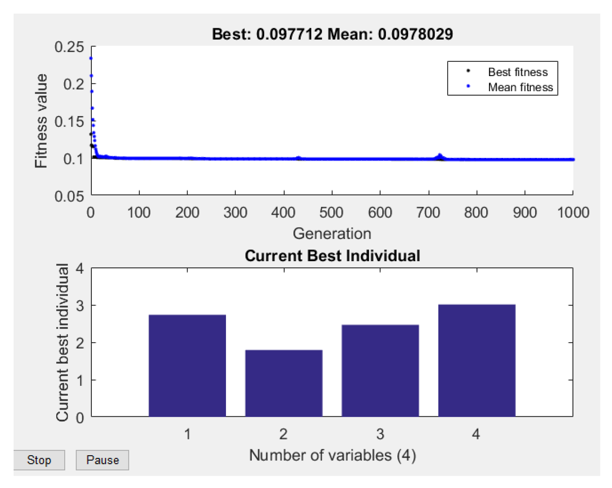
Taking the grindstone wear (Gw), the material removal rate (MRR), and the total number of ground parts in a grinding cycle (N’p) as objective functions and grinding quality parameters as constraints, a multi-objective optimization problem in the shoe-type centerless grinding operation for the 6208 inner ring raceway surfaces was proposed. The genetic algorithm was used to solve the multi-objective optimization problem. Based on that, the optimal solution set was found as follows: Snf =15.38 µm/s, Vw = 6.00 m/min, af = 11.76 µm, and Np = 20 parts. For this optimal condition, the predicted values of four output responses were as follows: Gw = 11.03 (µm), MRR = 0.45 (g/min), N’p = 20 (parts), Ra = 0.49 (µm), and Op = 2.62 (µm).
-
The optimal technology mode was applied into the real machining process for the inner ring raceway of the 6208_ball bearing made from SUJ2 alloy steel, and the outcome showed a much better result in comparison with default setting modes, while still ensuring the technology requirements. The obtained result also showed that the difference in experimental values and predicted values of the output parameters was within 5% of the range, indicating that the models that were proposed in the study are reliable.
-
Compared with the optimal technology modes in [2,3], the total number of ground parts in a grinding cycle (N’p) were increased by 20 times. This optimal mode would provide the greatest grindstone durability and machining productivity, while satisfying the requirements of part’s precision to improve efficiency in the shoe-type centerless grinding operation for the internal raceway of 6208_ball bearings on the 3MK136B grinder. Such results would help manufacturers deal with questions in deciding the best option in numerous choices of conditions for initial technology parameters in order to enhance efficiency in the shoe-type centerless grinding operation for internal raceway of 6208_ball bearings on the 3MK136B grinder.

Funding

This research received no external funding.

Conflicts of Interest

The authors declare no conflict of interest.

Nomenclature

RaPart’s surface roughness (µm).
GwGrinding wheel wear (µm).
OpThe oval of groove bottom diameter (µm).
MRRMaterial removal rate (g/mm).
SnfNormal feed rate for fine grinding (µm/min).
VwWorkpiece speed (m/min).
VSGrinding speed (m/min)
afThe depth of fine grinding (µm).
NpThe number of ground parts (part).
N’pThe total number of ground parts in a grinding cycle (part/cycle).
STCGThe shoe-type centerless grinding

References

  1. Jiang, J.; Ge, P.; Sun, S.; Wang, D. The theoretical and experimental research on the bearing inner ring raceway grinding process aiming to improve surface quality and process efficiency based on the integrated grinding process model. Int. J. Adv. Manuf. Technol. 2017, 93, 747–765. [Google Scholar] [CrossRef]
  2. Chang, Z.; Jia, Q.; Yuan, X.; Chen, Y. Optimization of the grinding process to improve the surface integrity of bearing raceways. Int. J. Adv. Manuf. Technol. 2017, 91, 4243–4252. [Google Scholar] [CrossRef]
  3. Chang, Z.; Jia, Q. Optimization of grinding efficiency considering surface integrity of bearing raceway. SN Appl. Sci. 2019, 1, 679. [Google Scholar] [CrossRef] [Green Version]
  4. Charmley, J.E. Geometric and dynamic analysis of shoe-type centerless grinding. In Master of Science in Mechanical Engineering; Massachusetts Institute of Technology: Cambridge, MA, USA, 1992. [Google Scholar]
  5. Saravanan, R.; Asokan, P.; Sachidanandam, M. A multi-objective genetic algorithm (GA) approach for optimization of surface grinding operations. Int. J. Mach. Tools Manuf. 2002, 42, 1327–1334. [Google Scholar] [CrossRef]
  6. Slowik, A.; Slowik, J. Multi-objective optimization of surface grinding process with the use of evolutionary algorithm with remembered Pareto set. Int. J. Adv. Manuf. Technol. 2007, 37, 657–669. [Google Scholar] [CrossRef]
  7. Khan, A.M.; Jamil, M.; Mia, M.; Pimenov, D.Y.; Gasiyarov, V.R.; Gupta, M.K.; He, N. Multi-Objective Optimization for Grinding of AISI D2 Steel with Al2O3 Wheel under MQL. Materials 2018, 11, 2269. [Google Scholar] [CrossRef] [Green Version]
  8. Tran, T.T.; Luu, A.T.; Nguyen, Q.T.; Le, H.K.; Nguyen, A.T.; Hoang, T.D.; Le, X.H.; Banh, T.L.; Pi, V.N. Optimization of Replaced Grinding Wheel Diameter for Surface Grinding Based on a Cost Analysis. Metals 2019, 9, 448. [Google Scholar] [CrossRef] [Green Version]
  9. Tung, L.A.; Hong, T.T.; Cuong, N.V.; Ky, L.H.; Muthuramalingam, T.; Trung, D.D.; Hung, L.X.; Vu, N.P. Optimization of Manufacturing Time in Surface Grinding. Advances in Engineering Research and Application. In Proceedings of the International Conference on Engineering Research and Applications, Thai Nguyen, Vietnam, 1–2 December 2019; Nguyen, D., Vu, N., Tien Long, B., Puta, H., Eds.; Springer: Cham, Switzerland, 2020; Volume 104, pp. 566–574. [Google Scholar] [CrossRef]
  10. Tran, T.H.; Tuyen, V.T.; Tung, L.A.; Do, T.V.; Nguyen, T.Q.D.; Nguyen, T.T.; Giang, T.N.; Pi, V.N. Improvement of Wheel Life by Optimization of Dressing Parameters in Surface Grinding of SKD11 Steel. Mater. Sci. Forum 2021, 1020, 68–74. [Google Scholar] [CrossRef]
  11. Hong, T.T.; Vu, N.N.; Phan, N.H.; Giang, N.T.; Tu, N.T.; Hung, L.X.; Danh, B.T.; Tung, L.A. Multi Response Optimization of Dressing Conditions for Surface Grinding SKD11 Steel by Hai Duong Grinding Wheel Using Grey Relational Analysis in Taguchi Method. Advances in Engineering Research and Application. In Proceedings of the International Conference on Engineering Research and Applications, Thai Nguyen, Vietnam, 1–2 December 2020; Sattler, K.U., Nguyen, D.C., Vu, N.P., Long, B.T., Puta, H., Eds.; Springer: Cham, Switzerland, 2021; Volume 178, pp. 560–571. [Google Scholar] [CrossRef]
  12. Rudrapati, R.; Pal, P.K.; Bandyopadhyay, A. Modeling and optimization of machining parameters in cylindrical grinding process. Int. J. Adv. Manuf. Technol. 2015, 82, 2167–2182. [Google Scholar] [CrossRef]
  13. Pi, V.N.; Hung, L.X.; Tung, L.A.; Long, B.T. Cost Optimization of Internal Grinding. J. Mater. Sci. Eng. B 2016, 6, 291–296. [Google Scholar] [CrossRef] [Green Version]
  14. Deresse, N.C.; Deshpande, V.; Taifa, I.W.R. Experimental investigation of the effects of process parameters on material removal rate using Taguchi method in external cylindrical grinding operation. Eng. Sci. Technol. Int. J. 2020, 23, 405–420. [Google Scholar] [CrossRef]
  15. 3ахаров, O.B.; Бpжозовский, Б.M. Ensuring Technical Reliability in Centerless Grinding Process, 2nd ed.; Ministry of Education and Science of the Russian Federation, Federal Agency for Education: Saratov State Technical University: Saratov Oblast, Russian, 2010; pp. 140–185. [Google Scholar]
  16. Young, H.T.; Chen, D.J. Online dressing of profile grinding wheels. Int. J. Adv. Manuf. Technol. 2006, 27, 883–888. [Google Scholar] [CrossRef]
  17. Rascalha, A.; Brandão, L.C.; Filho, S.L.M.R. Optimization of the dressing operation using load cells and the Taguchi method in the centerless grinding process. Int. J. Adv. Manuf. Technol. 2013, 67, 1103–1112. [Google Scholar] [CrossRef]
  18. Paoletti, A.; Ilio, A.D. A monitoring system for metal matrix composites grinding based on a noncontact capacitive sensor. J. Manuf. Technol. Res. 2011, 3, 197–210. [Google Scholar]
  19. Dong, W.P.; Anne chino, L.; Webster, J.A. On-line measurement of grinding wheel wear using acoustic emission. Proc. Soc. Precis. Eng. 1996, 11, 566–571. [Google Scholar]
  20. Lachance, S.; Warkentin, A.; Bauer, R. Development of an automated system for measuring grinding wheel wear flats. J. Manuf. Syst. 2003, 22, 130–135. [Google Scholar] [CrossRef]
  21. Yu, H.; Lu, Y.; Wang, J. Study on wear of the grinding wheel with an abrasive phyllotactic pattern. Wear 2016, 358, 89–96. [Google Scholar] [CrossRef]
  22. Fan, K.C.; Lee, M.Z.; Mou, J.I. On-Line Non-Contact System for Grinding Wheel Wear Measurement. Int. J. Adv. Manuf. Technol. 2002, 19, 14–22. [Google Scholar] [CrossRef]
  23. Thang, V.T.; Tuan, N.A.; Tiep, N.V. Evaluation of grinding wheel wear in wet profile grinding for the groove of the ball bearing’s inner ring by pneumatic probes. J. Mech. Sci. Technol. 2018, 32, 1297–1305. [Google Scholar] [CrossRef]
  24. Yin, S.; Nguyen, D.T.; Chen, F.; Tang, Q.; Duc, L.A. Application of compressed air in the online monitoring of surface roughness and grinding wheel wear when grinding Ti-6Al-4V titanium alloy. Int. J. Adv. Manuf. Technol. 2019, 101, 1315–1331. [Google Scholar] [CrossRef]
  25. ISO 492-2002. Rolling Bearings—Radial Bearings—Geometrical Product Specification (GPS) and Tolerance Values; ISO: London, UK, 2002. [Google Scholar]
  26. Kumar, K. Optimizing Material Removal Rate in Cylindrical Grinding Process through Taguchi Method. Master’s Thesis, National Institute of Technology, Odisha, India, June 2007. [Google Scholar]
  27. Nawawi, Z.S.B. Modelling of Material Removal Rate on Grinding Ductile Iron Using Water Based SIO2 Nano Coolant. Bachelor’s Thesis, University Malaysia Pahang, Pekan, Malaysia, June 2012. [Google Scholar]
  28. Di Ilio, A.; Paoletti, A.; D’Addona, D.M. Characterization and modelling of the grinding process of metal matrix composites. CIRP Ann. 2009, 58, 291–294. [Google Scholar] [CrossRef]
Figure 1. The schematic diagram and realistic image of 3MK136B bearing raceway grinder. 1. Charging trough; 2. swing arm of grinder loads/unloads automatically; 3. discharging trough; 4. the workbench; 5. servo motor for workpiece carriage; 6. ball screw; 7. motor for grinding wheel spindle; 8. motor for work arbor; 9. ball screw; 10. servomotor for dressing carriage; 11. dressing carriage; 12. diamond pen; 13. dresser part; 14. grinding wheel; 15. workpiece.
Metals 11 00893 g001
Figure 2. SJ400 roughness tester.
Metals 11 00893 g002
Figure 3. Images and diagram for the structural principles of the measurement equipment D022.
Metals 11 00893 g003
Figure 4. The schematic diagrams and realistic images of the experiment system. (a) The schematic of the system setup; (b) the image of the real experiment system.
Metals 11 00893 g004
Figure 5. The principal scheme of the shoe-type centerless grinding process for bearings’ inner ring raceway. 1, 2: Ring supports; 3: electromagnetic fixture; 4: grinding wheel; 5: grinding workpiece.
Metals 11 00893 g005
Figure 6. Working cycle diagram of 3MK136B bearing raceway grinder.
Metals 11 00893 g006
Figure 7. The technical requirements of the finish grinding operation for the groove of the 6208_ball bearing’s inner ring [25].
Metals 11 00893 g007
Figure 8. Diagram for distribution of the part’s accuracy tolerance zone and the grinding wheel’s wear according to the number of ground parts (a) The distribution diagram corresponding to the first cutting mode of Snf = 12.5 µm/s, Vw = 12 m/min, af = 15 µm. (b) The distribution diagram corresponding to the second cutting mode of Snf = 12.5 µm/s, Vw = 12 m/min, af = 10 µm. + O: Oval level of raceway bottom’s diameter. * Ra: Surface roughness of raceway. x Hz: Wear value at the edge of the curving edge surface of grinding wheel. (All the values are shown in the diagram with a plotting scale of 1, with the exception of the Ra value using a plotting scale of 10).
Metals 11 00893 g008
Figure 9. The algorithm diagram for the GA software program to solve the optimization problem of process parameters in the raceway surface grinding operation.
Metals 11 00893 g009
Figure 10. Progress searching for the optimal solution using the GA, running on the MATLAB environment.
Metals 11 00893 g010
Table 1. Main technical specifications of the 3MK136B grinder.
NoTechnical SpecificationsValue/Name
1Model3MK136B (made in China)
2Maximum outer diameter of workpieceФ82 (mm)
3Radius of inner ring raceway0 ÷ 15 (mm)
4Rotation speed of wheel spindle60 (m/s)
Table 2. Specifications of grinding wheel.
JIS CodeGradeGrainBondOuter Diameter of Grinding Wheel (mm)Width of Grinding Wheel (mm)
A100L5VSoftWhite fused aluminaVitrified5008
Table 3. The chemical composition of SUJ2 alloy steel (JIS G4051).
C (%)Si (%)Mn (%)Ni (%)Cr (%)P (%)S (%)Mo (%)Co (%)
0.95~1.100.15~0.350.25–0.45<0.251.4–1.65max 0.25max 0.25<0.08<0.2
Table 4. The specifications of the SJ400 roughness meter.
NoSpecificationsValue/Name
1ModelSJ400 (Made in Japan)
2Measuring range800 μm
3Resolution0.000125 µm
4Accuracy0.1 µm
Table 5. Input process parameters and design levels.
No.Input ParametersLabelUnitExperimental Levels
Low LevelBase LevelHigh Level
1The normal feed rate of fine grindingSnfμm/s5.012.520.0
2The speed of the workpieceVwm/min6.012.018.0
3The depth of fine grindingafμm101520
4The number of ground partsNpParts102030
Table 6. Experimental data from 81 experiments.
No.Snf
(µm/s)
Vw
(m/min)
tf
(µm)
Np
(Parts)
Gw
(µm)
Ra
(µm)
Op
(µm)
MRR
(g/min)
15610107.80.392.50.237
251210108.10.422.30.237
351810108.30.442.20.237
412.5610108.40.443.00.260
512.51210108.80.472.70.260
612.51810109.10.492.70.260
720610108.80.473.70.273
8201210109.20.503.30.273
9201810109.50.523.20.273
105615107.90.412.80.250
1151215108.30.442.70.250
1251815108.50.462.50.250
1312.5615108.60.463.20.271
1412.51215109.00.492.80.271
1512.51815109.30.512.80.271
1620615109.00.493.80.284
17201215109.50.523.50.284
18201815109.70.543.30.284
195620108.10.423.30.256
2051220108.40.452.80.256
2151820108.60.472.70.256
2212.5620108.80.473.20.274
2312.51220109.20.513.00.274
2412.51820109.40.533.00.274
2520620109.20.503.80.295
26201220109.60.543.70.295
27201820109.90.563.50.295
2856102010.00.432.50.237
29512102010.50.462.30.237
30518102010.70.482.20.237
3112.56102011.00.483.00.260
3212.512102011.50.512.70.260
3312.518102011.80.532.70.260
34206102011.40.513.70.273
352012102012.00.543.30.273
362018102012.30.573.20.273
3756152010.20.452.80.250
38512152010.70.482.70.250
39518152011.00.502.50.250
4012.56152011.20.503.20.271
4112.512152011.70.532.80.271
4212.518152012.00.562.80.271
43206152011.70.533.80.284
442012152012.20.573.50.284
452018152012.60.593.30.284
4656202010.40.463.30.256
47512202010.90.492.80.256
48518202011.20.512.70.256
4912.56202011.40.513.20.274
5012.512202011.90.553.00.274
5112.518202012.20.573.00.274
52206202011.90.543.80.295
532012202012.40.583.70.295
542018202012.80.613.50.295
5556103011.70.452.50.237
56512103012.20.482.30.237
57518103012.60.502.20.237
5812.56103012.80.503.00.260
5912.512103013.40.542.70.260
6012.518103013.70.562.70.260
61206103013.40.533.70.273
622012103014.00.573.30.273
632018103014.40.593.20.273
6456153012.00.472.80.250
65512153012.50.502.70.250
66518153012.90.522.50.250
6712.56153013.10.523.20.271
6812.512153013.70.562.80.271
6912.518153014.00.582.80.271
70206153013.70.553.80.284
712012153014.30.593.50.284
722018153014.70.623.30.284
7356203012.20.483.30.256
74512203012.70.522.80.256
75518203013.10.542.70.256
7612.56203013.30.543.20.274
7712.512203013.90.583.00.274
7812.518203014.30.603.00.274
79206203013.90.573.80.295
802012203014.60.613.70.295
812018203015.00.643.50.295
Table 7. Regression statistics for regression equations.
SourSurface Roughness Model (Ra)Grinding Wheel Wear Model (Gw)Oval Level Model (Op)Material Removal Rate Model (MRR)
R20.99780.99960.86850.9896
Adjusted R20.99770.99950.86340.9862
Standard Error (θ)0.00310.00210.04580.0001
The dispersion (σ)0.270.132.940.1
Table 8. Optimal solution found by the MATLAB program using the GA.
Snf
(µm/s)
Vw
(m/min)
af
(µm)
Np
(part)
Gw
(µm)
Ra
(µm)
Op
(µm)
MRR
(g/min)
15.386.0011.762011.030.492.620.45
Table 9. Outcome result with optimal solution of the found cutting mode parameters.
Gw
(µm)
Error of GwRa
(µm)
Error of RaOp
(µm)
Error of OpMRR
(g/min)
Error of Q
10.64.06%0.482.08%2.651.13%0.434.65%
Publisher’s Note: MDPI stays neutral with regard to jurisdictional claims in published maps and institutional affiliations.

