Article

A Comprehensive Study of Dynamic Recrystallization Behavior of Mg Alloy with 3 wt.% Bi Addition

1
School of Materials Science and Engineering, Hebei University of Technology, Tianjin 300130, China
2
PLA AAAAD, Hefei 230031, China
3
School of Materials Science and Engineering, Hefei University of Technology, Hefei 200039, China
4
School of Materials Science and Engineering, Taiyuan University of Technology, Taiyuan 030024, China
5
School of Materials Science and Engineering, Kyungpook National University, Daegu 41566, Korea
6
Magnesium Technology Innovation Center, Seoul National University, Seoul 08826, Korea
7
Tianjin Dongyi Magnesium Products Co., Ltd., Tianjin 301700, China
*
Author to whom correspondence should be addressed.
Metals 2021, 11(5), 838; https://doi.org/10.3390/met11050838
Submission received: 21 April 2021 / Revised: 15 May 2021 / Accepted: 17 May 2021 / Published: 20 May 2021

Abstract

:
The effect of the addition of bismuth on the dynamic recrystallization (DRX) behavior of the matrix has been investigated by comparing coarse grain pure Mg with the addition of 3 wt.% Bi, using a uniaxial compression test in the temperature range of 473–623 K and the strain rate of 0.01–10 s−1. The constitutive equation, processing map, microstructure, and texture evolution of the Mg-3Bi alloy were systematically investigated. The results showed that the Bi addition could refine the grain size and accelerate the DRX process. The DRX kinetics is discussed in detail, accompanied by extensive characterization employing EBSD analysis. The DRX of the Mg-3Bi alloy depended on the deformation temperature rather than the strain rate. The {10–12} tensile twin appeared at 573 K/0.01–0.1 s−1, and discontinuous DRX (DDRX), continuous DRX (CDRX) as the main mechanism in the case of 573 K/0.01 s−1, while the dominant mechanism was DDRX when deformation temperature and strain rate increased. Particle-stimulated nucleation (PSN) was also involved in the DRX of this new RE-free Mg alloy.

Graphical Abstract

1. Introduction

Magnesium and its alloys, as one kind of the lightest structural metal materials, can meet the demand of the weight-saving content requirement in the fields of aerospace, automotive, and 3C electronics, because of their inherent high specific strength and stiffness, productive impact resistance, green energy consumption, and recyclability. Thus, they have become one of the fastest-growing materials in industrial applications worldwide [1,2]. However, the poor mechanical properties and severe anisotropy hinder the utilization of wrought Mg alloys. In particular, the plastic deformation of magnesium at room temperature is confined to basal slip and twinning below 498 K, owing to a few slip systems. So, how to improve the performance of wrought magnesium alloys has become a critical issue to be solved [3,4].
It is well known that alloying and grain refinement are impressive strategies to overcome such drawbacks [5]. Generally, the addition of rare earth elements (RE) into the magnesium matrix can effectively weaken the basal texture and activate non-basal texture to promote the plastic deformation of the matrix [6], but the strategy would increase the industrial costs. Thus, it is essential to find a novel way to exploit new magnesium alloys containing cheaper elements instead of RE [7]. Nowadays, bismuth (Bi) added into the magnesium alloys could precipitate a Mg3Bi2 phase on the prismatic surface of the matrix with outstanding thermal stability, similar to the Mg−RE intermetallic phase, suggesting the Bi takes a superior aging response to improve strength [8,9,10]. Besides, our previous results have shown that Mg−Bi-based alloys represented enhanced ductility and improved high strength with extraordinary extrudability [11,12]. Especially, the stacking faults, partial dislocations, and interface segregation also associated with Bi addition in pure Mg are revealed by HRTEM [13,14].
Moreover, in the subsequent simple thermal−mechanical processes, such as extrusion, the mechanical properties of Mg−Bi alloys could be promoted further, under the collective effect of precipitate strengthening and fine grain strengthening to meet the demand of low-cost industrial products. However, magnesium alloy is prone to DRX, due to low stacking fault energy, which is the main softening mechanism governing the microstructural evolution [15,16]. As we all know, the DRX mechanism can be divided into continuous DRX (CDRX), discontinuous DRX (DDRX), and twinning-induced DRX (TDRX). Furthermore, the different DRX mechanisms would have an influential effect on the mechanical properties of the matrix. Hence, it is essential to investigate the impact of Bi on the DRX behavior of the matrix to obtain excellent mechanical properties from the Mg−Bi alloys. Although some attempts have been carried out to better understand the DRX mechanism in Mg−Bi-based alloys, most of them were focused on complex ternary or quaternary alloy systems with a high content of Bi addition and fine grain size. Based on our experience, the low content or dilute composition of Mg−Bi based alloys have also given attractive results for high performance. However, very few studies have paid attention to the effect of the thermal deformation behavior of the Mg−Bi binary alloy with coarse-grained structure.
Therefore, this work has mainly elucidated the hot deformation behaviors of pure and 3 wt.% Bi-doped Mg alloys through constitutive analysis, map-processing establishment and the microstructural evolution under various temperatures and strain rates. Especially, the effect of Bi on the DRX mechanism was investigated. We hope the present research can not only provide a crucial development basis and theoretical support for the application of a wrought Mg−Bi-based alloy, but also want to figure out the DRX story behind it.

2. Materials and Methods

The raw materials selected in our experiment were industrial pure magnesium (99.9 wt.%) and commercial pure Bi ingots (99.9 wt.%), which were smelted and stirred in an electrical furnace at 1023 K with SF6 and CO2 as protective gas and poured into the stainless-steel mold preheated to 473 K. The as-cast Mg-3Bi (wt.%) ingot with a diameter of 60 mm and the height of 150 mm was homogenized at 753 K for 12 h, followed by water-quenching.
The cylindrical hot deformation samples with the dimension of Φ8 mm × 12 mm were cut from the core of the specimen via electrical discharge machining. The isothermal compression experiment was carried out on the thermomechanical simulator (Gleeble-3180, DSI, New York, NY, USA) at the temperature range of 473–623 K with an interval of 50 K and in the strain rate range of 0.01–10 s−1 under vacuum conditions. All samples were compressed to a true strain of 0.7–0.8, followed by water-quenching in order to preserve the deformed microstructure. High-temperature lubricating oil and graphite sheets were used to reduce friction.
The cross-sectional samples were cut and polished parallel to the compression direction (CD), followed by etching using the mixed solution of 4.2 g picric acid,10 mL acetic acid, 70 mL ethanol, and 10 mL distilled water. The microstructure characterization was observed using optical microscopy (OM, OLYCIA M3, DQZH Ltd., Beijing, China), scanning electron microscopy (SEM, Nova Nano SEM450, FEI Company, Hillsboro, OR, USA) equipped with energy-dispersive X-ray spectroscopy (EDS). In addition, the texture and grain size were characterized used an SEM (Quanta 650, FEI Company, Hillsboro, OR, USA) equipped with Aztec EBSD acquisition system. These samples were prepared by grinding and polishing by electro-polishing in a solution of 85 mL ethanol and 15 perchloric at liquid nitrogen. The EBSD analysis was performed with a step size of 0.5 μm and accelerating voltage setting of 20 kV. The data were detected and analyzed by Channel 5 software (3.1, Oxford Instruments, Hobro, Denmark). The preparation parameters of EBSD were basically consistent with previous research [17].

3. Results and Discussion

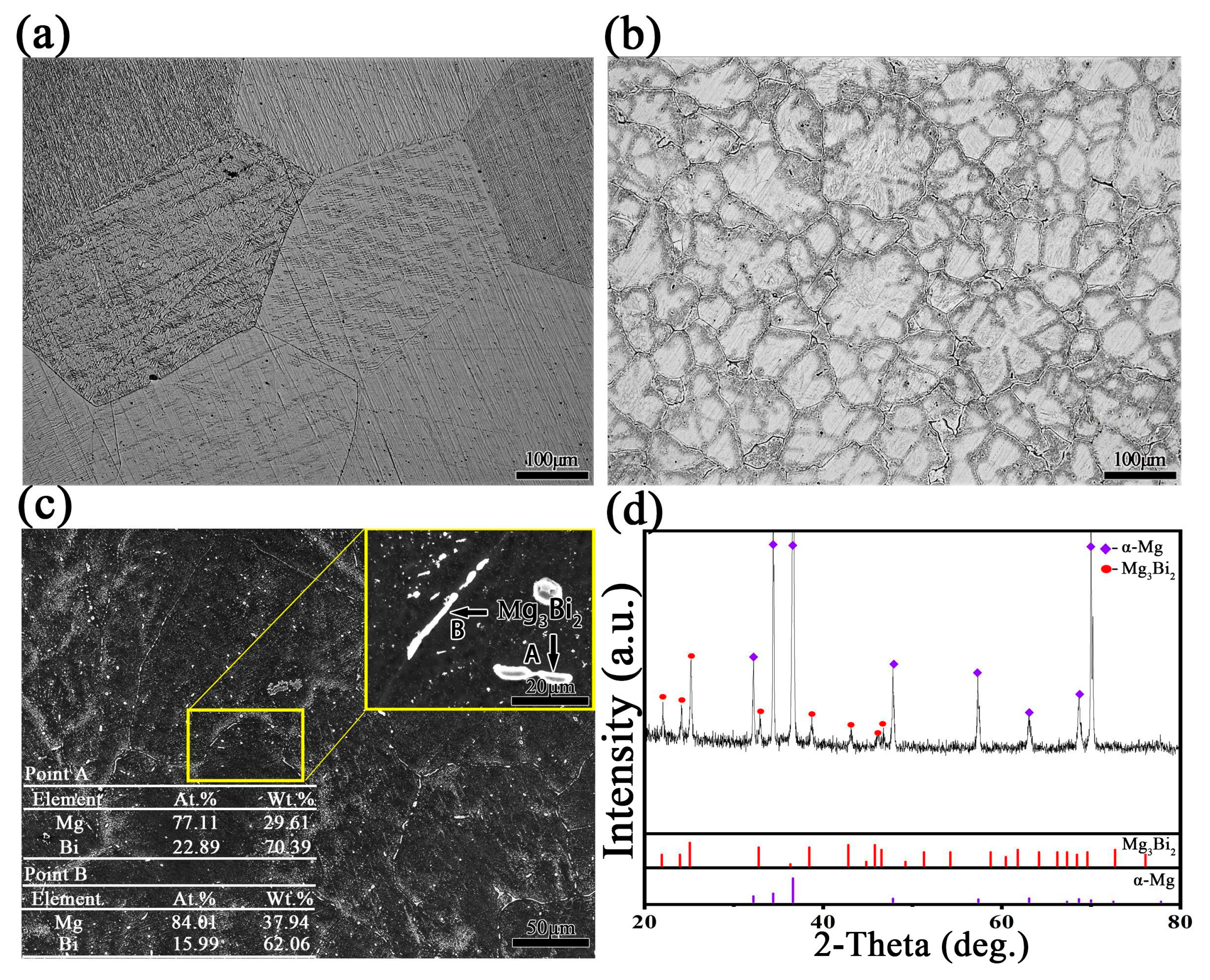
3.1. The Initial Microstructure of Pure Mg and Mg-3Bi Alloy

Figure 1 shows the initial microstructure of as-cast pure Mg and Mg-3Bi alloy. As can be seen from Figure 1a,b, the addition of Bi can apparently refine the grain compared with the pure magnesium. The average grain size changed from ~500 μm to ~133 μm after 3 wt.% Bi was added into pure Mg, which can be explained by the growth restriction factor (GRF) theory [18]. Moreover, there were many precipitated phases at the grain boundary or the grain interior. The EDS analysis and XRD pattern have shown that these dispersed particles in the Mg matrix were Mg3Bi2 phase, as such kinds of second particles remain undissolved after homogenization (see Figure 1c,d). Our previous analysis also confirmed these particles by utilization of transmission electron microscope [19].

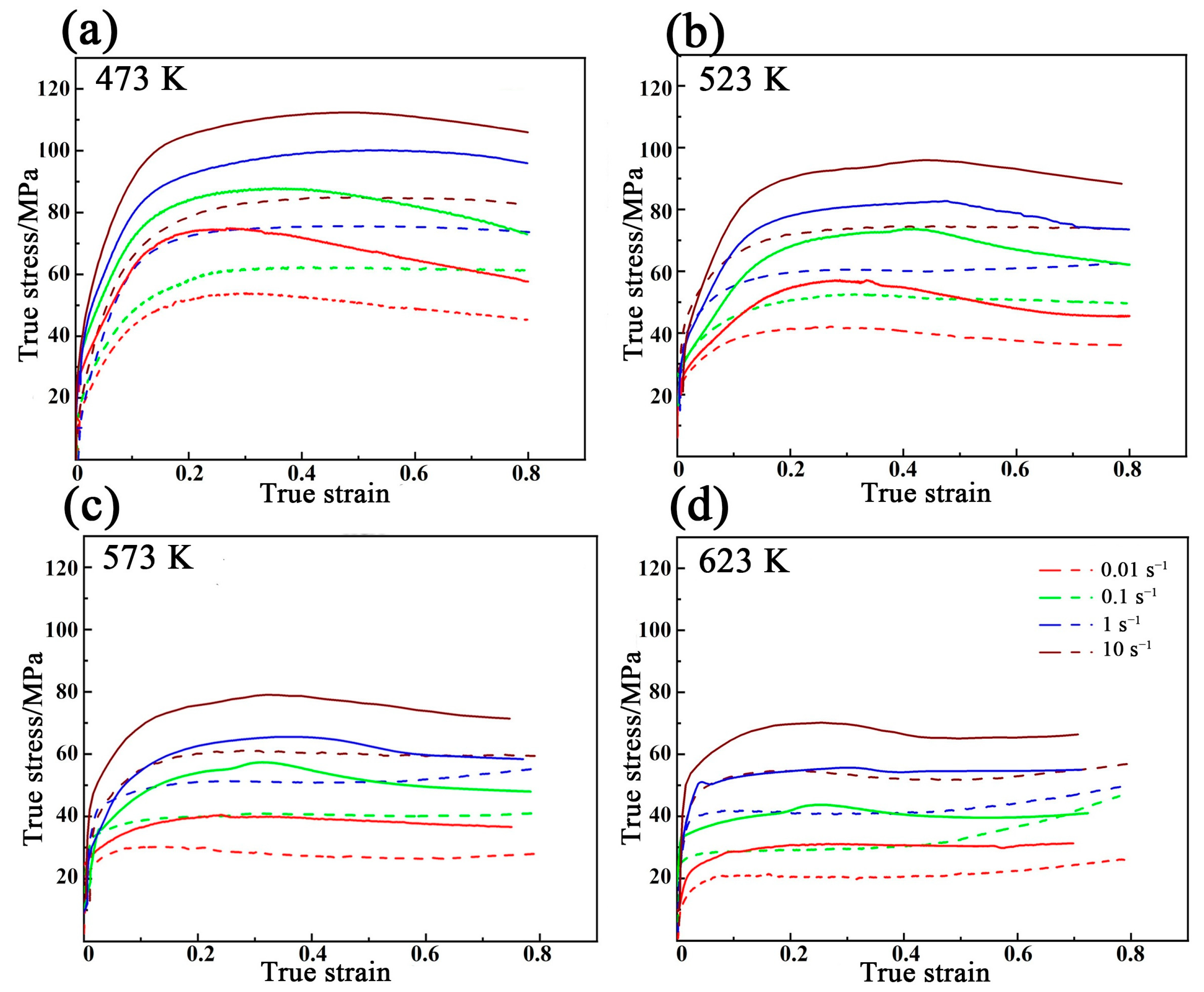
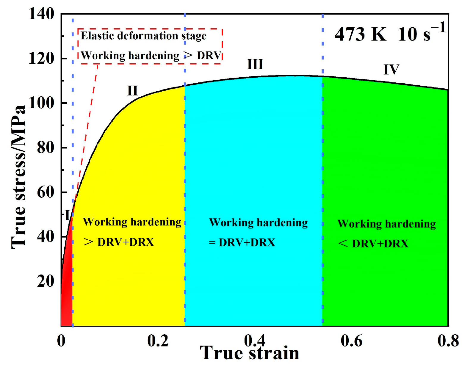
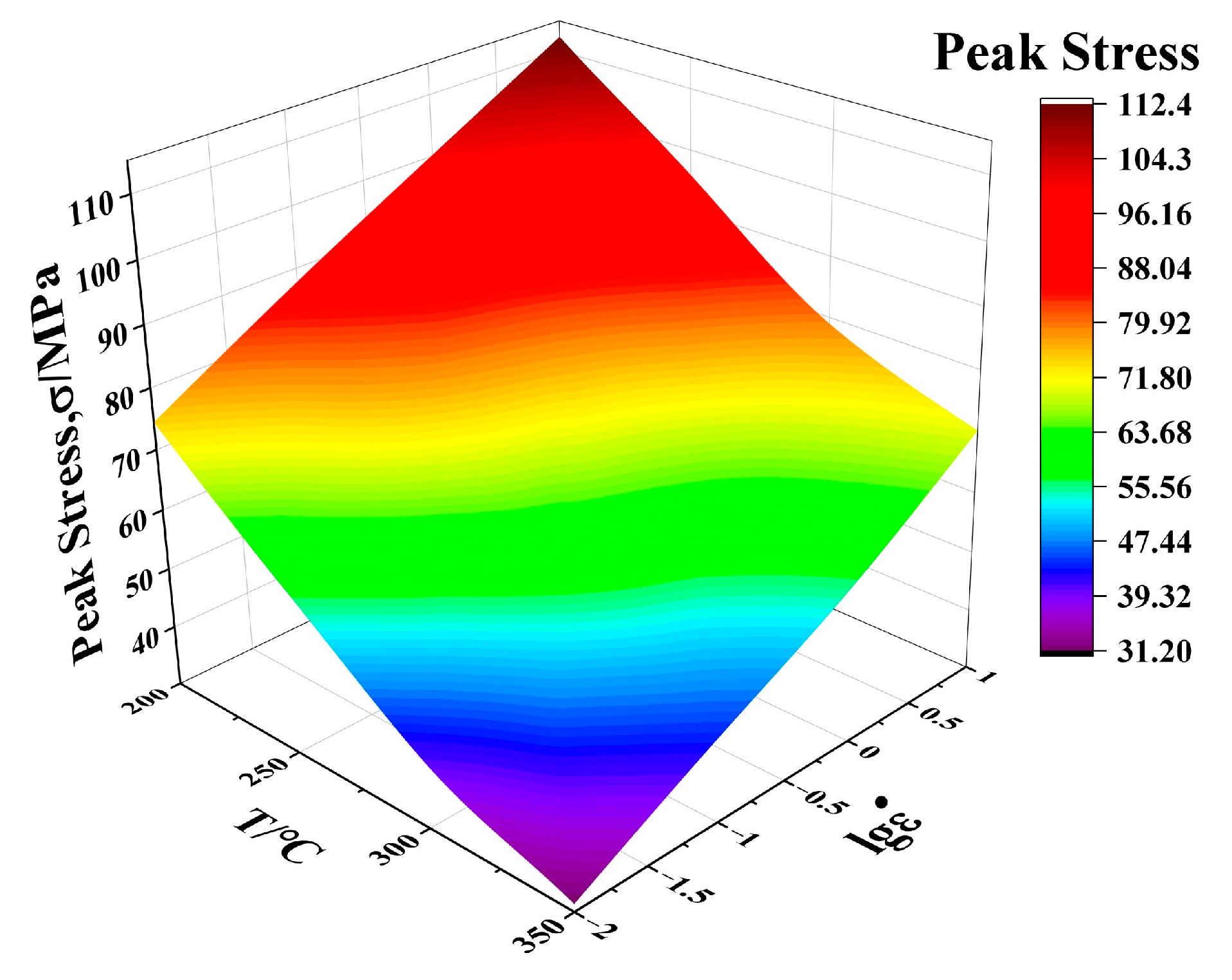
3.2. Flow Stress−Strain Behavior

Figure 2 shows the typical flow curves of the pure Mg (legend with dash lines) and Mg-3Bi (legend with solid lines) alloy at different temperatures with strain rates of 0.01, 0.1, 1 and 10 s−1. Obviously, as shown in Figure 2, both deformation temperature and strain rate can affect the flow stress. Especially, all the curves had the characteristics of a unimodal dynamic recrystallization (DRX) behavior and peak stress in both materials, which indicated the occurrence of DRX during hot compression [20]. The mechanism is the dislocation accumulation that cannot be relieved by dynamic recovery (DRV) with further deformation due to the low stacking fault energy, which leads to an increase in dislocation density and promotes the occurrence of DRX. In addition, it is worth mentioning that the true stress of pure Mg is lower than that of Mg-3Bi alloy under the same conditions. Meanwhile, the time to reach peak stress was also faster with the Bi addition, indicating that the recrystallization phenomenon also occurred in the very early stages.
Figure 3 shows the flow stress variation, which can be simply divided into four stages by using the 473 K with 10 s−1 of Mg-3Bi alloy as an example. The flow stress rose sharply with the increasing strain because of work hardening caused by dislocation plugging and multiplication dominating during the first stage. Then the flow stress growth rate slowed down as the strain continued to increase. This was mainly due to the softening effect of DRV and the effect of the dynamic softening consecutive increase. The peak stress was reached when the balance between working hardening and softening was attained. Eventually, as a result of the gradually enhanced DRX offsetting the work hardening, the flow curve showed a downward trend and then attained the steady-state.
In addition, the variation of peak stress with temperature and strain rate is shown in Figure 4. As can be seen, the peak stress constantly changed between 31 MPa to 112 MPa under the different deformation circumstances. For instance, the peak stress of the Mg-3Bi alloy increased from 74 MPa to 112 MPa when the strain rate increased from 0.01 s−1 to 10 s−1 at 473 K. Because there was not enough time for DRX or DRV at a higher strain rate, this led to the enhanced dislocation density and the strain hardening [21,22]. Besides, as the temperature increased from 473 K to 623 K, while the peak stress decreased from 112 MPa to 70 MPa at 10 s−1, which attributed to the annihilation and rearrangement of dislocations via the mobility of the grain boundaries [23]. Moreover, the peak strain corresponding to each peak stress was between 0.2 and 0.5 under the various conditions. The formation of subgrains related to nonbasal slipping was more easily activated and the peak stress appeared earlier as the temperature increased. Similarly, the lower strain rate provided sufficient time for dynamic recrystallization (DRX) to release the stored stress, and the peak value shifted to a smaller strain direction [24]. In contrast, the peak stress increased when the strain was over 0.8 at 623 K, regardless of strain rates. This may be due to the overlapped upper and lower deformation zones. However, this is not a rigorous definition of the stress−strain behavior because of the complexity of the hot deformation mechanism of Bi-bearing Mg alloy. Further analysis of the constitutive equation is indispensable.

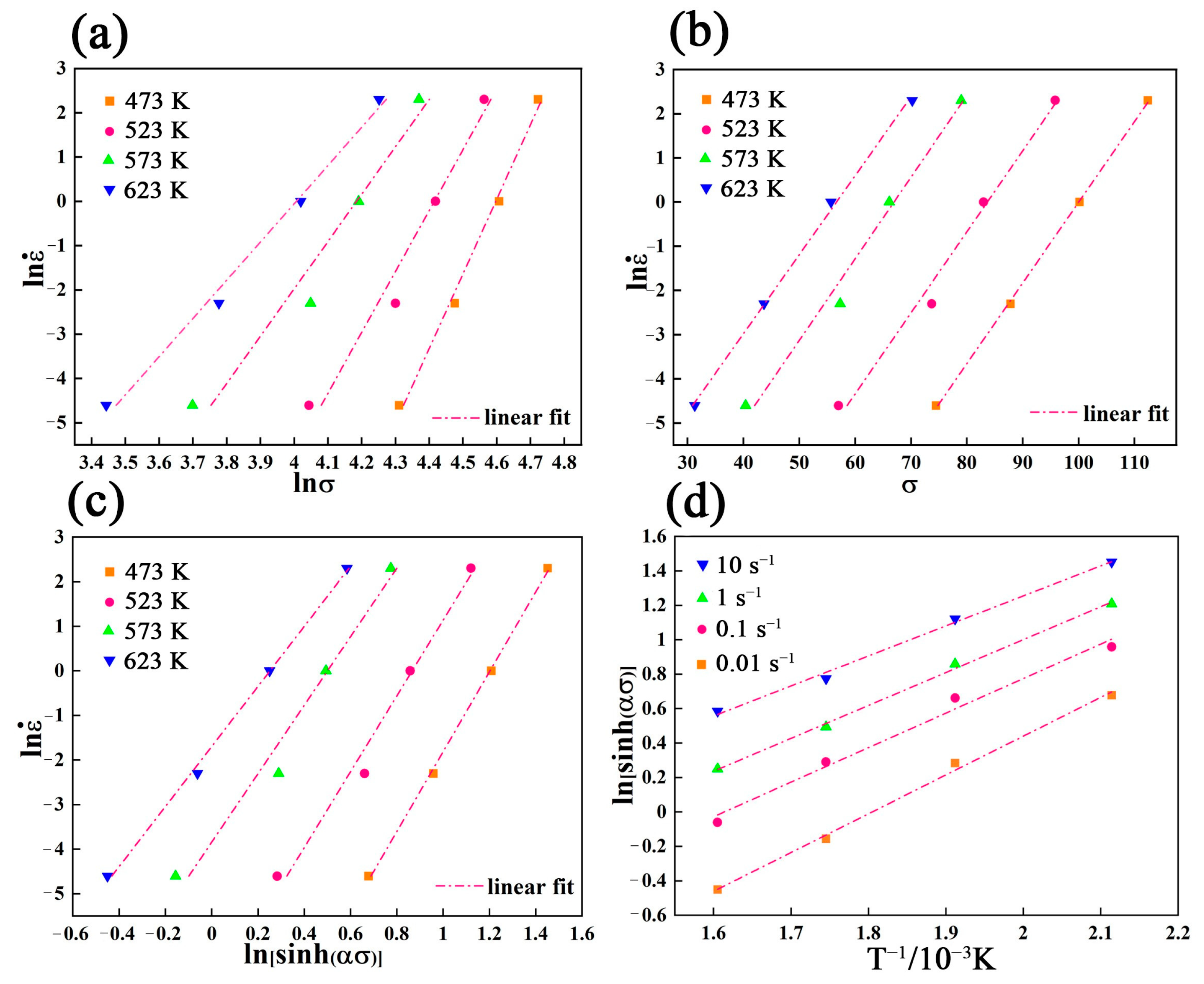
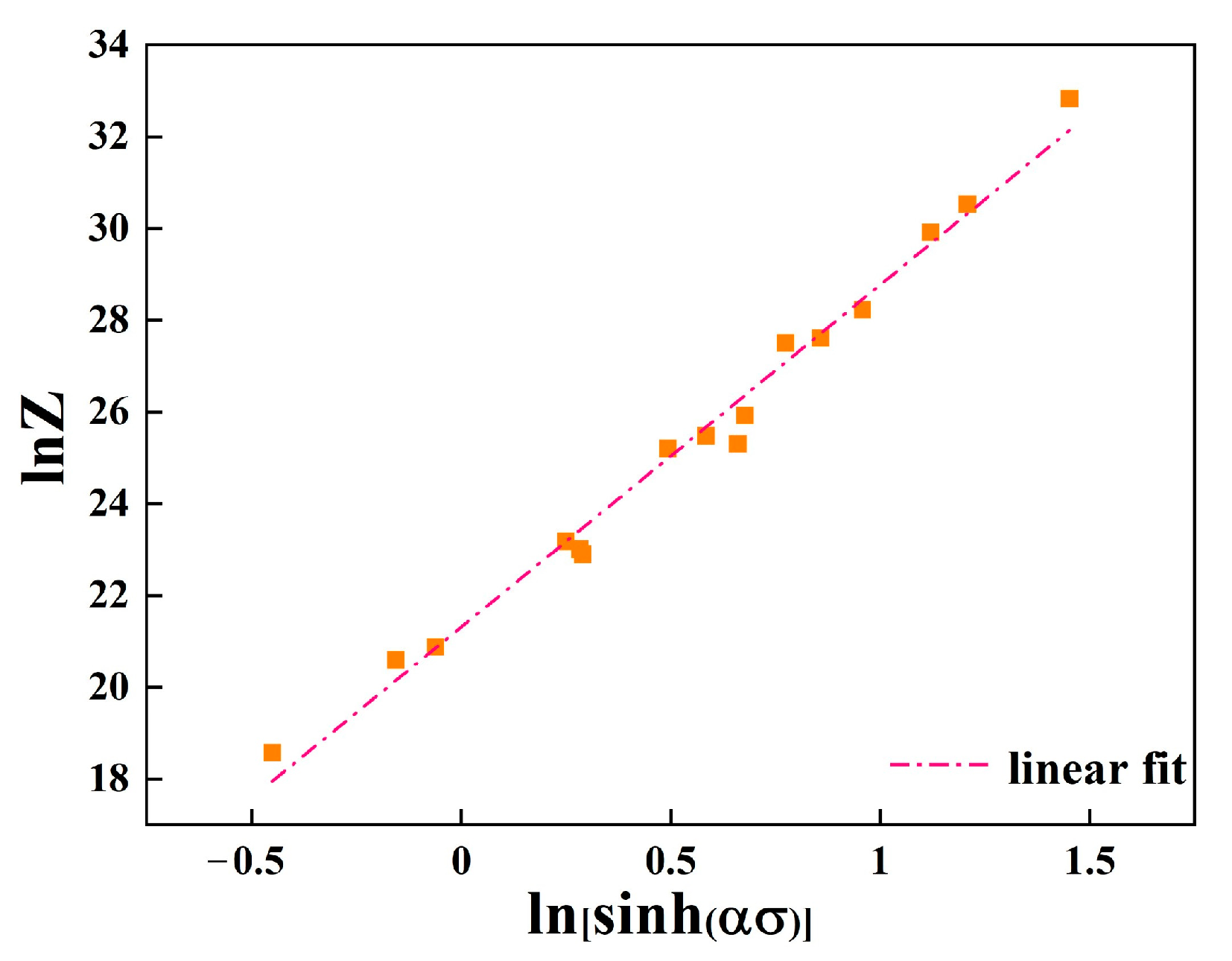
3.3. The Constitutive Equation of Mg-3Bi Alloy

In order to show the quantitative relationship among the thermal parameters, in other words, the dependence of flow stress on the strain, strain rate, and temperature can be expressed via the constitutive equation. At present, most scholars use the Arrhenius-type constitutive equation to express the relationship between flow stress (σ), strain rate ( ε ˙ ) and temperature (T) during the hot deformation of magnesium alloys, as expressed by Equation (1) [25,26,27].
ε ˙ = A 1 σ n 1 exp ( Q R T )
ε ˙ = A 2 exp ( β σ ) exp ( Q R T )
ε ˙ = A [ sinh ( α σ ) ] n exp ( Q R T )
In the above formula, Q is the deformation activation energy (kJ mol−1), which implies the deformation difficulty of the material. T is the absolute temperature(K),   ε ˙ is the strain rate (s−1), σ is the flow stress (MPa), A1 and A are the temperature-independent material constants, n 1 and n are the stress exponents, α and β are the fitting parameters of the equation. R is the molar gas constant. (8.314 J/(K*mol)). Furthermore, α, β and n have the following relationship, which is expressed as follows [28]:
α = β / n 1
Generally, the lower stress levels (ασ < 0.8), higher stress levels (ασ > 1.2) and all stress levels adapt to Equations (1)–(3), respectively [29].
The process of hot plastic deformation is caused via the combination of work hardening and dynamic softening inside, and the constitutive relation is highly nonlinear. The power function and exponential function equations cannot be suitable for high stress and low-stress cases due to the consideration of thermal deformation as a thermal activation process. Therefore, the constitutive equation in the form of hyperbolic sine function seems more suitable for general cases [28]. In addition, the characteristic stress in the constitutive equation can be divided into steady stress and peak stress. In general, the peak stress can be calculated as the characteristic stress of Mg alloys [28,30]. In this study, the peak stress is used to construct the constitutive equation.
The natural logarithms on both sides of Equations (1) and (2) can be transformed into Equations (5) and (6), respectively.
ln ε ˙ = ln A 1 + n 1 ln σ ( Q R T )
ln ε ˙ = ln A 2 + β σ   ( Q R T )
According to Equations (5) and (6). The relationship between ln ε ˙ -lnσ and ln ε ˙ -σ is obtained as shown in Figure 5a,b, respectively. In particular, the value of n 1 and β can be calculated by the average slope of the straight line in ln ε ˙ -lnσ plots and ln ε ˙ -σ plots, respectively. Finally, the value of n 1 and β is 12.24 and 0.182. Thus, the value of α can be obtained as 0.0149 according to α = β/ n 1 .
In order to obtain the value of thermal deformation activation energy Q, the partial differential of T and ε ˙ in Equation (3) can be obtained according to the following equation [31]:
Q = R { ln ε ˙ ln [ sinh ( α σ ) ] } T { { ln [ sinh ( α σ ) ] } ( 1 / T ) } ε ˙
Similarly, the linear fitting graph of ln ε ˙ - ln [ sinh ( α σ ) ] and ln [ sinh ( α σ ) ] - 1 / T can be obtained by taking the natural logarithm on both sides of Equation (3). Equation (8) as shown below:
ln ε ˙ = ln A + n ln [ sinh ( α σ ) ] ( Q R T )  
As shown in Figure 5c,d, it can be seen that the linear relationship between the above parameters is maintained well. Based on the results of the linear fitting, the average slope of { ln ε ˙ ln [ sinh ( α σ ) ] } T and { { ln [ sinh ( α σ ) ] } ( 1 / T ) } ε ˙   is 9.11 and 1.723, respectively. Therefore, it can be calculated that the value of deformation activation energy Q is 130.501 kJ/mol.
The combined effect of temperature and strain rate on flow stress can be simplified by the Zener−Hollomon parameter ( Z parameter for short), which can be calculated using Equation (8).
Z = ε ˙ exp ( Q R T ) = A [ sinh ( α σ ) ] n
ln Z = ln A + n ln [ sin h ( α σ ) ]
Equation (10) can be obtained by taking the natural logarithm on both sides of Equation (9). The relationship diagram is drawn according to the data and the linear fitting is carried out by the least square method (see Figure 6), the calculated n value is 8.926 and the intercept corresponding ln A is 26.2989, in which the value of A is obtained as 2.64 × 10¹¹.
Finally, the constitutive equation of Mg-3Bi alloy can be obtained by substituting the parameters calculated above and expressed as follows:
ε ˙ = 2.64 × 10 11 [ sinh ( 0.0147 σ ) ] 9.11 exp ( 130500.95 R T )

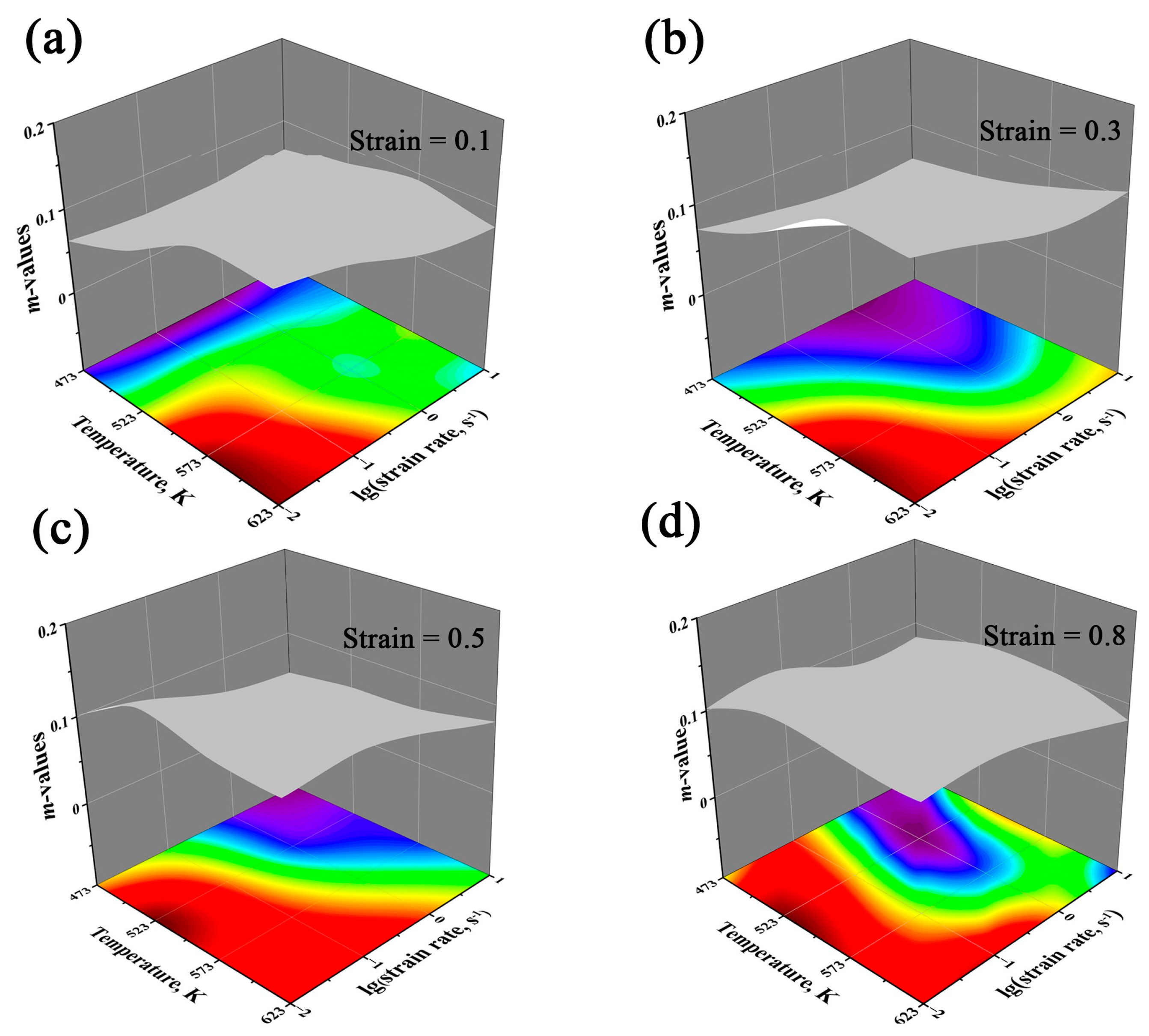
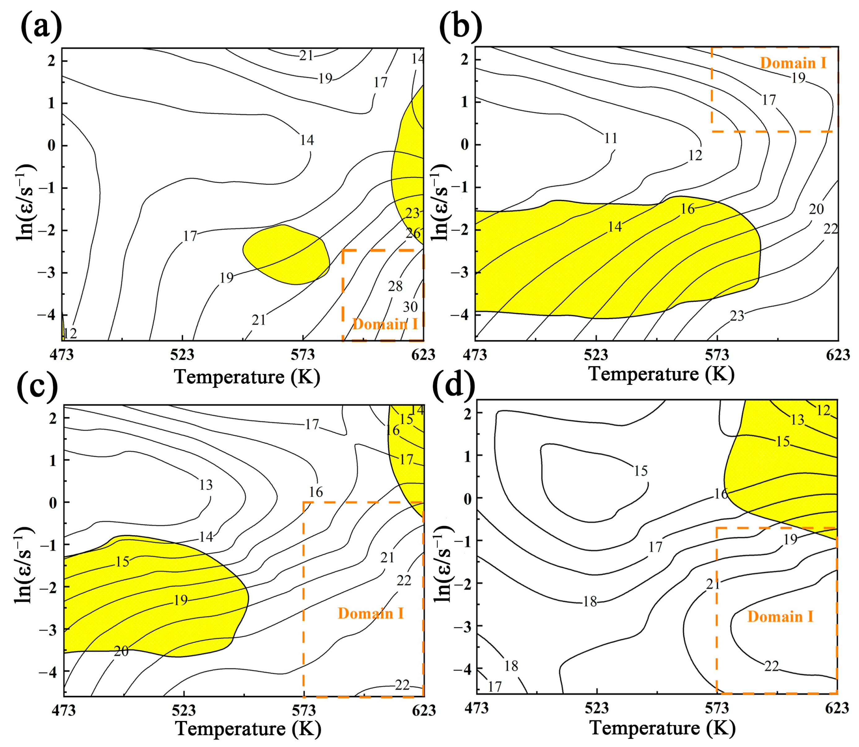
3.4. Construction of the Hot Processing Map for Mg Containing Bi

For the sake of the hot deformation explanation, the processing map (power dissipation map + instability map [32]) of Mg-3Bi alloy is constructed on the basis of the dynamic materials model (DMM) theory, which can reflect the relationship between the heat and energy dissipation rate of plastic deformation, as well as the development of microstructure [33,34]. Based on the DMM, the total power P absorbed by the specimen in unit time during hot deformation is dissipated by two parts. The G is the energy consumed by the material due to plastic deformation, most of which is converted into thermal energy, and a small part is stored in the material in the form of crystal defect energy. The J is related to the transformation of microstructure such as DRV and DRX, which is the energy consumed by the microstructure evolution of the material in the process of hot deformation [35]. The expression is as follows:
P = σ · ε ˙ = G + J = 0 ε ˙ σ d ε ˙ + 0 σ ε ˙ d σ  
The strain rate sensitivity factor m is formed by the change rate of the parameters G and J.
m = d J d G = ε ˙ d σ σ d ε ˙ = ln σ ln ε ˙
During steady-state deformation, the energy will be stored, and the material will not be dissipated (m = 0 or m < 0), which corresponds to high strain rate deformation, and the internal structure usually consisting of adiabatic shear band, twinning, and micro-crack, and even producing deformation instability (m > 1). However, the material is in the ideal dissipation, and the dissipative covariance J reaches the maximum (m = 1) if materials are considered as ideal dissipation, but it is nigh on impossible to achieve.
In the analysis of the multifactor quantitative processing test, the relationship between test index and multiple test factors can be analyzed by the response surface method. According to Equation (13), the m values at different strain rates and temperatures under a given strain (0.1, 0.3, 0.5, and 0.8) were calculated, respectively, and the 3D-response surfaces were plotted, as shown in Figure 7. It can be seen that the 3D-surface shapes under various strains were roughly similar, namely, the strain showed no effect on the value of m. However, the fluctuation surface in Figure 7 showed that the deformation mechanism involved altered significantly and needed to be further identified.
In order to reflect the dissipation characteristics of the material during hot deformation, the power dissipation factor is proposed and conforms to the following relationship:
η = 2 m m + 1
Generally, the higher the hot working efficiency of the material showing, the higher the value of m and η. The domain with the high value of η can be marked as a safe domain and the mechanisms of DRV and DRX are activated to attain the best performance [36]. An instability criterion was proposed that there would be a few defects, such as the adiabatic shear band, localized flow instability, and cracks, which would affect the properties of the material. The criterion equation of flow instability can be calculated as follows [32,33]:
ξ ( ε ˙ ) = ln ( m m + 1 ) ln ε ˙ + m < 0
Especially, the material instability occurs when the rheological instability parameter (ξ) is negative. Taking the deformation temperature as the abscissa and the shared logarithm of the strain rate as the ordinate, the power dissipation map and the corresponding rheological instability map are drawn respectively. Finally, the hot processing map of Mg-3Bi alloy under certain strains is plotted by overprinting these maps.
The processing maps of Mg-3Bi alloy under different strains (0.1, 0.3, 0.5, 0.8) are shown in Figure 8. The numerical value in the figure represents the percentage of power dissipation factor under different deformation conditions, and the same value is represented by contours. The yellow shadow area represents the rheological instability areas, where the ξ value is negative. It can be seen that the value of η basically increased with the increase of deformation temperature and the decrease of strain rate. As shown in Figure 8, the instability region was remarkably different under specific strain, indicating that the strain was more sensitive to the instability region. When the strain was 0.1, the instability domain was concentrated in the medium temperature−low strain rate domain and the high temperature−medium strain rate domain. With the strain increased to 0.2, the instability region was located in the low temperature-low strain rate region and the medium temperature−low strain rate domain. With the further increase of strain, as shown in Figure 8c,d, the instability region was transformed from a low temperature−low strain rate zone and high temperature−high strain rate domain to a part (i.e., high temperature−high strain rate domain).
The optimum processing performance depends on the high-power efficiency and positive ξ values (see domain I in Figure 8). In addition, the materials have intense DRX and DRV with few internal defects in the safety region. However, the occurrence mechanism of DRX needs to be further discussed.

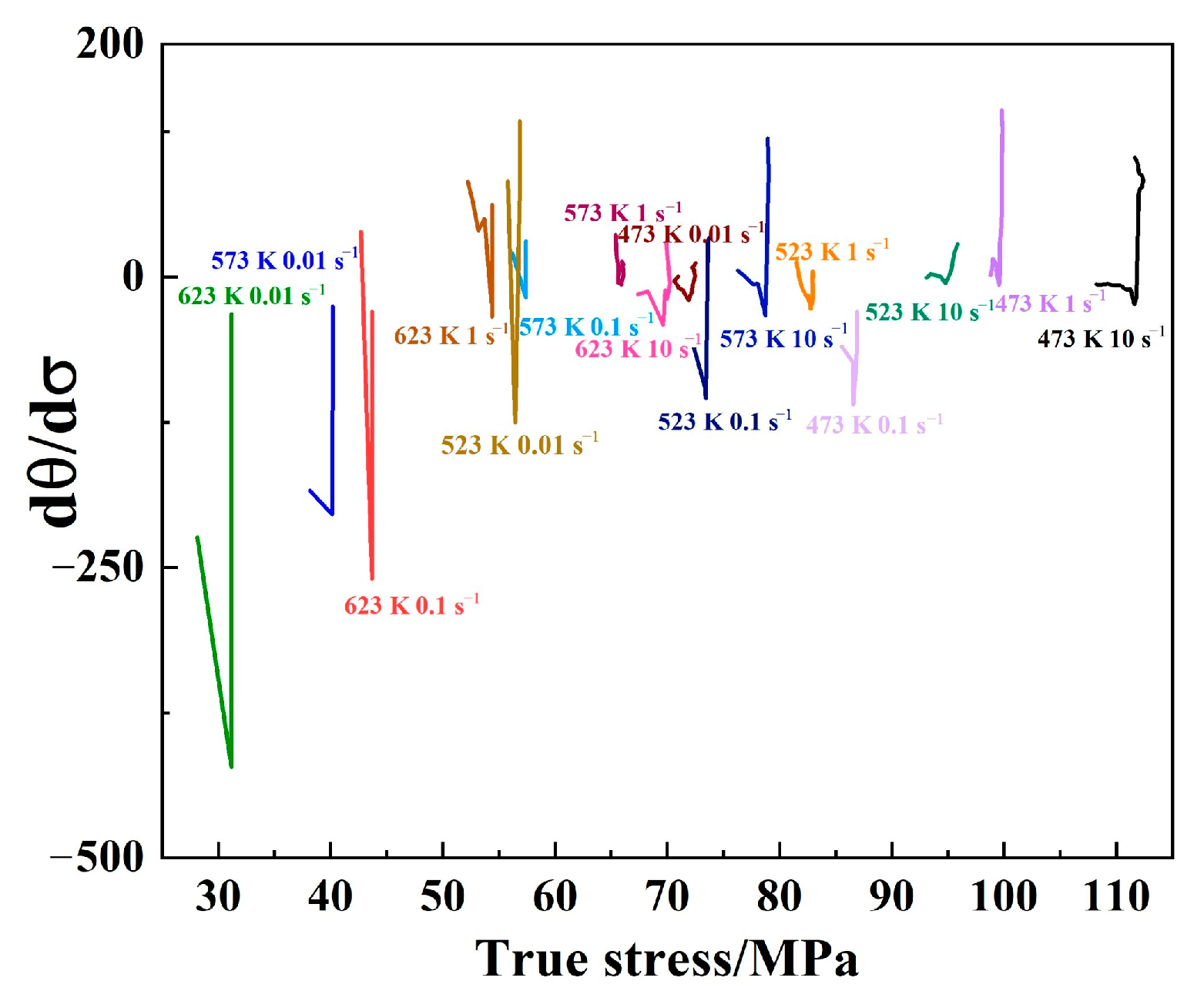
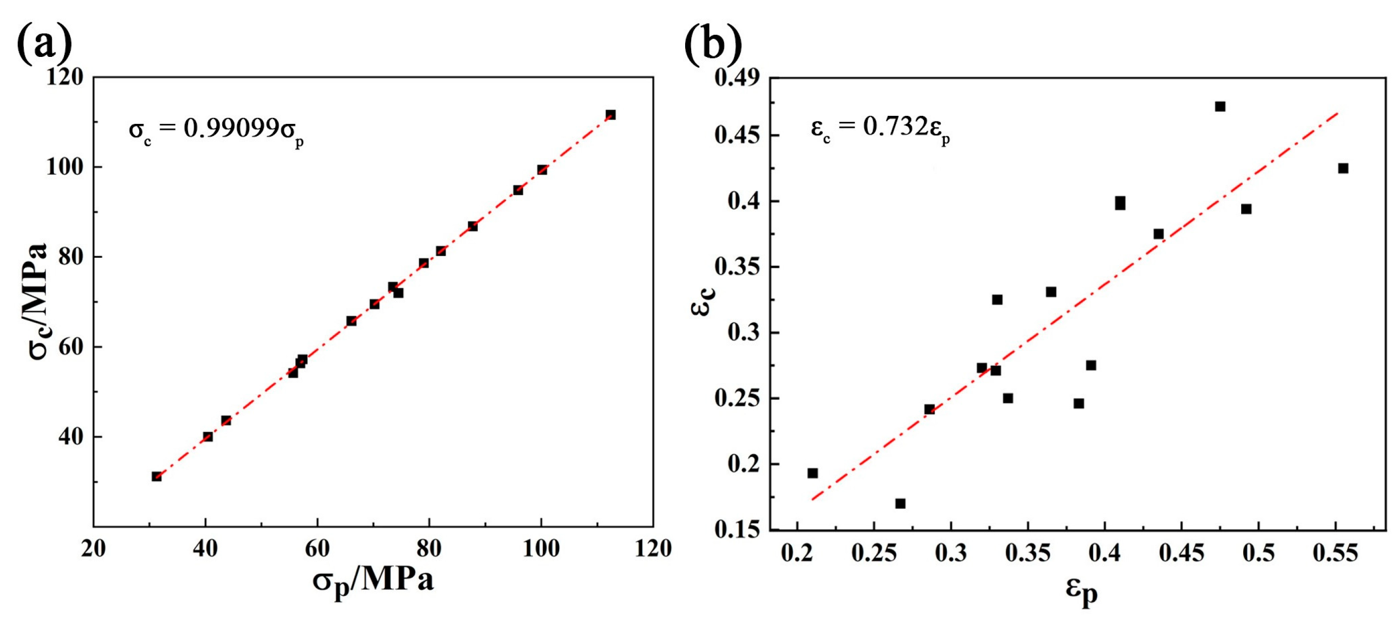
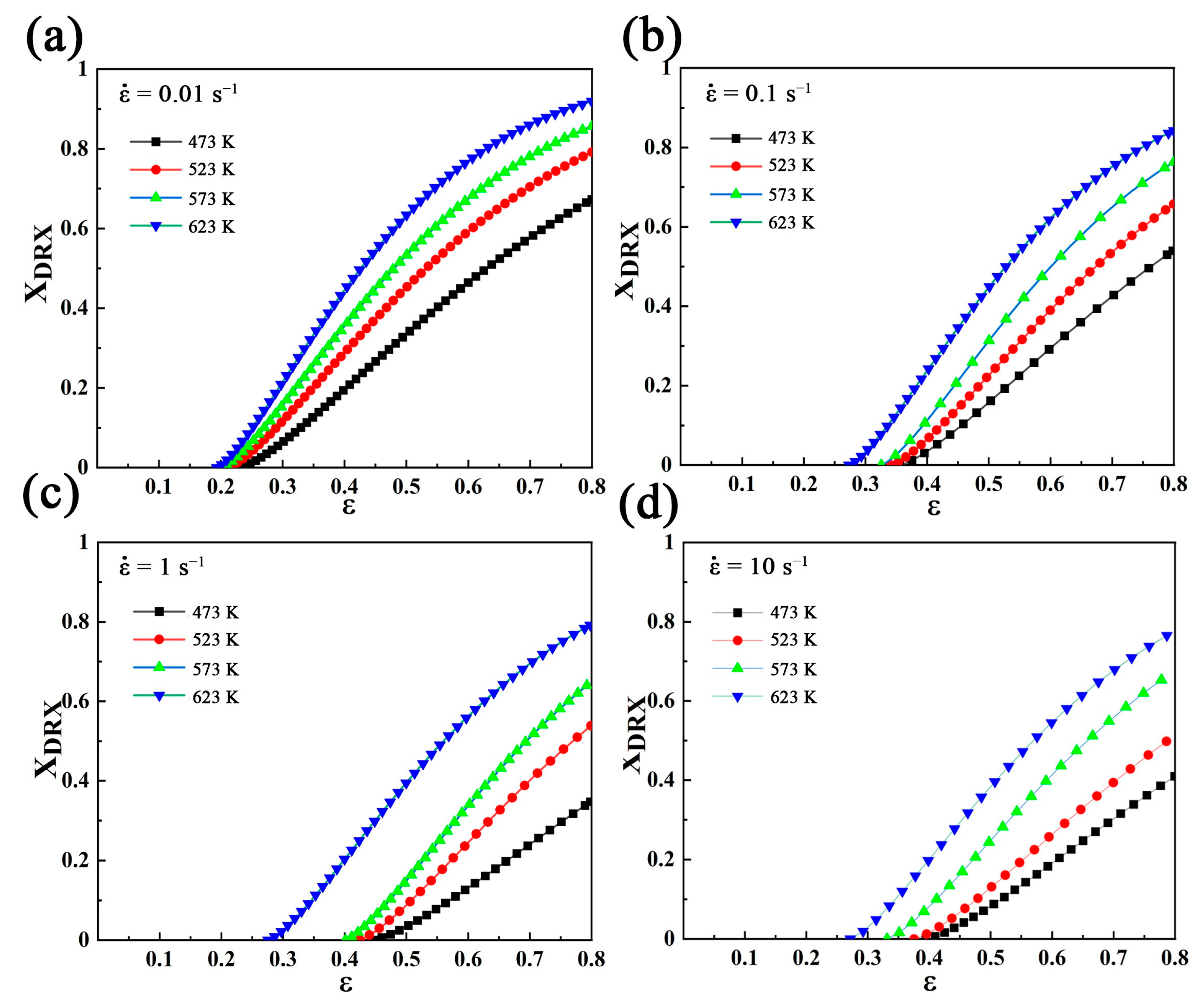
3.5. DRX Kinetics in Case of Mg-3Bi Alloy

In this section, the kinetics of DRX are discussed, to achieve this goal, the work hardening rate Θ (Θ =   σ ε ) is calculated in order to determine the peak stress accurately [37]. Figure 9 shows the relationship between the work hardening rate (Θ) and the flow stress (σ) at 523 K and 1 s−1 as a simple display, and every parameter is used to calculate the volume fraction of DRX. Positive Θ indicates that work hardening is dominant. On the other hand, dynamic softening plays a major role when Θ is negative. σp and σc are peak stress and critical stress, respectively. The σp is defined as the stress at Θ = 0, and σsat is named the saturation stress and the value is calculated through the intersection point of the tangent σc and Θ = 0. σss is called steady-state stress, which means the work hardening and dynamic softening achieve balance when Θ = 0 again. The stress σ * corresponding to the maximum softening rate is obtained when Θ reaches the minimum. The different state of σ corresponds to ε, respectively.
The curve of working hardening rate (Θ) against flow stress (σ) under different conditions is summarized in Figure 10. Apparently, the peak stress increased with decreasing deformation temperature and increasing strain rate as expected. In addition, the softening effect intensified with increasing temperature, and the low strain rate provided more extensive time for DRX. Therefore, the peak stress can be reduced under the conditions of higher deformation temperature and lower deformation strain rate [34].
Figure 11 exhibits the derivate of Θ as a function of σ, in which the lowest point of the curve (i.e., inflection point) is, namely, critical stress (σc). Furthermore, the linear relationships of both σp-σc and εp-εc are given in Figure 12. Based on all these parameters, we can develop DRX kinetics for better understanding during the deformation.
It is well known that DRX will be activated when the degree of dislocation accumulation reaches the critical value. In order to study the DRX evolution of the Mg-3Bi alloy during thermal−mechanical processing, the establishment of the DRX dynamic model can well predict the volume fraction of DRX according to Equation (16) [38].
X DRX   =   1 exp   [ k ( ε ε c ε * ) n ]
where XDRX is volume fraction (Vf) of DRX, k and n are material constants, ε is the true strain, ε c is critical strain and ε * is the strain for the maximum softening rate.
Moreover, the Vf of DRX can be expressed as the softening fraction as follows:
X DRX   =   σ s a t 2 σ 2 σ s a t 2 σ s s 2
Equation (18) can be derived from taking the natural logarithms on both sides of Equation (16) twice, as seen below:
lnln ( 1 1 X DRX ) = ln K + n ln ( ε ε c ε * )
Combining all the Equations (16)–(18), to establish the linear relationship between ln ( ε ε c ε * ) and ln ln ( 1 1 X DRX ) , where the slope and intercept of the fitting line correspond to n = 1.35 and k = 1.2, respectively. Hence the final expression of the Vf of DRX is given by:
X DRX   =   1 exp   [ 1.2 ( ε ε c ε * ) 1.35 ]
Taking all the above experimental results into consideration, the predicted Vf of DRX varies with the deformation temperature and the strain rate, as revealed in Figure 13.
It can be clearly observed that Vf of DRX shows an upward trend with increasing strain. In addition, for a given temperature, the DRX volume fraction gradually decreased with the increasing of the strain rate. Similarly, when the strain rate was fixed, the Vf of DRX decreased to varying degrees as the temperature dropped. Moreover, the threshold of strain at high temperature was smaller than that of its counterpart at low temperature, indicating that DRX could occur more easily and earlier at elevated temperature. Oppositely, high strain rate and low temperature delayed the activation of DRX. Owing to the low diffusion rate at a lower temperature, a large number of twins and dislocations were arduous to move, which inhibited the DRX nucleation rate. The number density of dislocations accumulated rapidly and the stress concentration did not have enough time to be released at high strain rates, resulting in the postponed occurrence of DRX to be imaged.

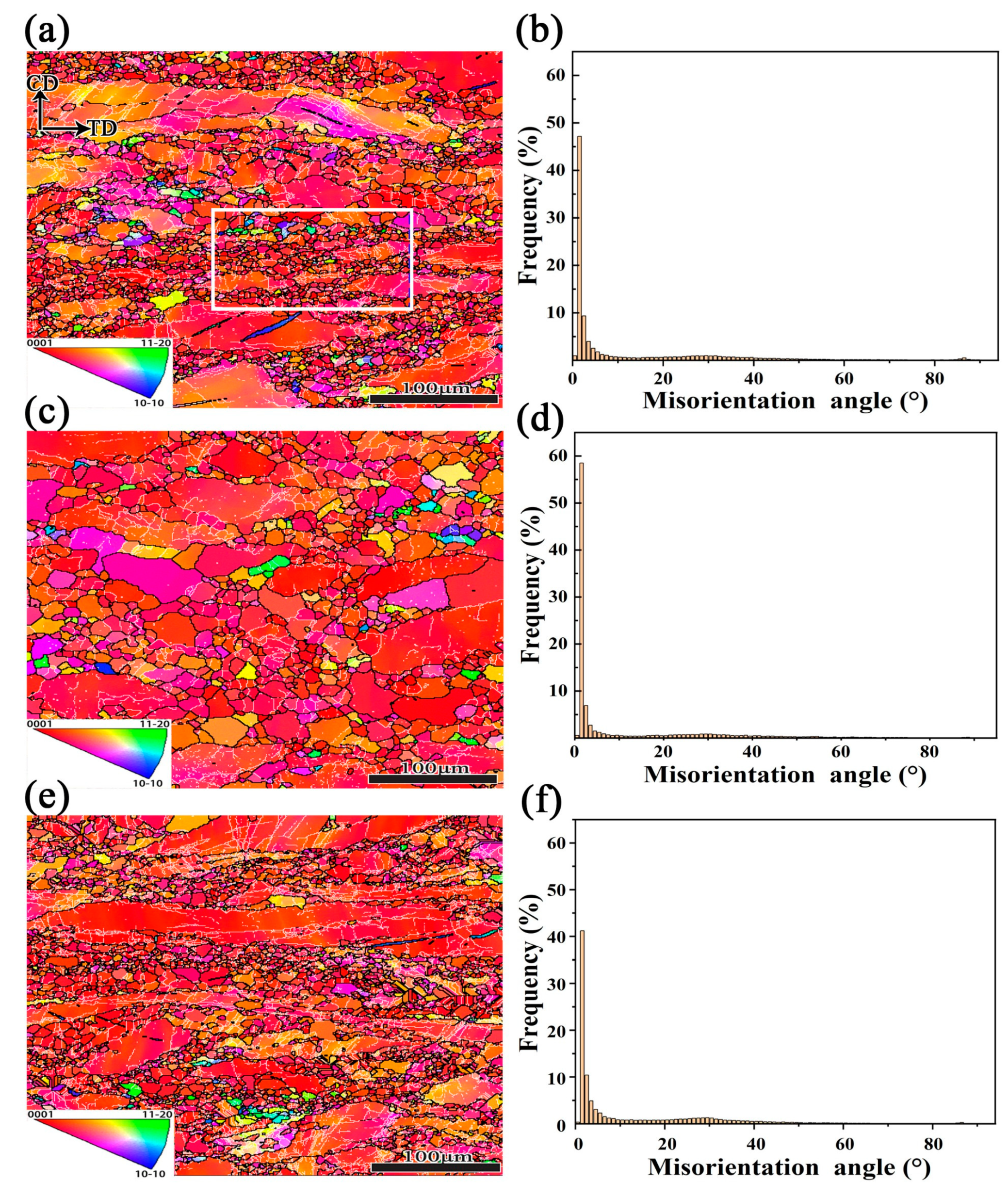
3.6. Microstructure Evolution and Interpretation of the DRX Mechanism

To verify the above results, the Mg-3Bi alloys with different strain rates and temperatures under certain characteristics were selected for EBSD observation. Figure 14 describes the inverse pole figures (IPF) and the misorientation angle distribution maps according to Figure 8. For the EBSD images, the black boundaries represented high angle grain boundaries (HAGBs) with a higher misorientation range larger than 15° and the white boundaries corresponded to low angle grain boundaries (LAGBs) with low misorientation range from 2° to 15°, respectively.
As can be seen from Figure 14a, the microstructure showed a typical bimodal structure with coarse deformed grains and fine DRX grains under the conditions of 573 K and 0.01 s−1. In particular, the DRX grains attached to the coarse grains are necklace-like, which is one of the characteristics of CDRX. The corresponding misorientation angle distribution is shown in Figure 14b, showing the largest proportion of LAGBs with a color gradient, which implies more subgrains containing a large number of dislocations in the specimen and store rich distortion energy. Compared with the sample of 623 K and 0.01 s−1 (see Figure 14c), the grain size increased a great deal, compared with the increase of temperature, which was mainly due to the further acceleration of the migration rate of grain boundaries (GBs) at high temperature. The accelerated expansion of GBs and the fusion of DRX grains resulted in the increase of grains [39]. It should be emphasized that the DRX is a thermal activation process, the structure will be homogenized and reconstructed as temperature increases, which in turn, can enhance the hot working performance [40]. As shown in Figure 14d, the fraction of LAGBs increased further, which means that the dislocation density continued to increase. Figure 14e represents the IPF and the misorientation angle distribution map at 573 K and 0.1 s−1. Compared with Figure 14a, with the lower strain rate applied, a more uniform microstructure was obtained, due to sufficient DRX with plenty of time to consume the internally stored stress. On the other hand, a decrease of LAGBs is related to more DRV of deformed grains [41]. Although both deformation temperature and strain rate play a very important role in the DRX behavior of Mg-3Bi alloy, the former seems more sensitive.
Figure 15 demonstrates the evolution of the texture of the Mg-3Bi alloy under different thermal deformation conditions in view of Figure 14. It can be seen that the texture characteristics are similar, which agrees well with the observations in Figure 14, in other words. The maximum pole density of {0001} was widely distributed at both ends of CD and the pole density {10–11} and {11–20} were preferentially along with the TD. In addition, the increase in deformation temperature (623 K) and strain rate (0.1 s−1) led to a stronger texture intensity, when taking Figure 15a as a benchmark. However, this texture evolution in coarse grain Mg alloy seemed little different to the fine grain one [23], indicating that the initial microstructure has a great influence on the final properties of wrought Mg alloys, and more attention should also be paid to the twinning behavior because it is prone to generate coarse grains without profuse precipitates [42].
Moreover, due to the limited-slip system that magnesium alloys can start at room temperature, to a certain extent twinning must play the characteristics of a coordinated slip system [43]. In order to analyze the existence or distribution of twins during thermal deformation, Figure 16a,b shows the distribution of grain boundaries in black as well as twin boundaries highlighted by the red line under various deformation conditions. It is obvious no twins were found in the state of 623 K and 0.01 s−1 as shown in Figure 14c. In contrast, the peaks in Figure 14b,f around 86° corresponded to the {10–12} tensile twin, which implies that twins are favorable to formation at low temperatures or high strain rates. The presence of tensile twins is effective for the rotation of the crystal grains during the compression tests. The twins reorientate the basal plane perpendicular to the loading direction and eventually form 86° lattice reorientation [44]. In order to understand the evolution in the orientation of twins and parent crystals. Figure 16c,d shows two regions with typical characteristics. According to the orientation distribution of the c-axis represented by Euler angle in {0001} pole figure (PF) and inverse pole figure (IPF), it can be found that the c-axis of the parent grains is mainly concentrated near-CD, and the c-axis of twins is close to the range of ND and TD. In addition, the c-axis of twins is more concentrated near ND as the strain rate increases.
To further analyze the texture modification between the recrystallized fine grains and the undeformed coarse grains, a part of the typical area (white rectangular domain in Figure 14a) of 573 K and 0.01 s−1 was extracted, as shown in Figure 17. Figure 17a shows the projections of recrystallized grains (G1–G4) with different orientations on the (0001) pole figure, presenting an almost randomized distribution (see Figure 17b). The orientation deviation from point A to point B at both ends of the recrystallized region fluctuated greatly due to the different orientations of recrystallization with weakened texture. The projections of coarsely deformed grains (G5–G7) on the (0001) pole figure were mainly concentrated on the two ends of CD. At the same time, the volatility from point C to point D was gentle and had a similar crystal orientation, which indicates that the coarsely deformed grains strengthen the <0001>//CD texture. (see Figure 17c,d).
In addition, the grains marked by arrow B were bulged, as shown in Figure 18a. The localization of dislocation slip makes the stress imbalance in the high-density dislocation region eventually lead to the local migration of the original grain boundary to form a “bulge”, which is evidence of DDRX [45]. Moreover, the black particles shown by arrow C, were undissolved Mg−Bi second phases, which could not be indexed in the EBSD, but were confirmed in Figure 1c,d. Meanwhile, there were LAGBs associated with the particles, which might indicate that particles stimulate nucleation (PSN) [46]. Moreover, there were LAGBs accumulating and expanding outward at the parent grain boundary (see arrow D), which would continue to transform into HAGBs with the development of strain, and eventually, new recrystallized grains would be formed.
One of the most obvious characteristics for the judging of CDRX behavior is the gradual increase of misorientation from the center to the edge of the parent grains. Figure 18b shows the cumulative misorientation distribution from the parent grain center to the grain boundary, as shown by line A, which indicates the misorientation increases obviously. Generally, the dislocations near the grain boundary are rearranged and the movable dislocations enter the subgrain boundary in the subsequent deformation, and then the trapping of lattice dislocations on the LAGBs leads to the emergence of stronger misorientation, the growing DRX nuclei can accumulate adequate misorientations to form HAGBs [47]. Thus, it can be concluded that the CDRX and DDRX mechanisms occurred simultaneously at 573 K/0.01 s−1.
Meanwhile, two other typical domains (623 K/0.01 s−1 and 573 K/0.1 s−1) are also given in Figure 18c,e. The serrated and bulging phenomena were found at GBs, which proved that the DDRX mechanism was activated. This type of grains usually introduces a strong strain gradient near GBs. Meanwhile, the misorientation gradient from point E and point F to the edge of the GBs was relatively lower and stable (see Figure 18d,f). Therefore, it can be concluded that the predominant mechanism is DDRX in the case of 623 K/0.01 s−1 and 573 K/0.1 s−1. In short, the migration ability of GBs is enhanced and DDRX is more likely to occur with the increase of deformation temperature and strain rate.
Finally, Figure 19 summarized the Schmid Factor (SF) maps classified with various deformation mechanisms (i.e., basal/prismatic/pyramidal slip and extension/contraction twinning) under the different conditions of the Mg-3Bi alloy. It can be seen that the characteristics of each deformation mechanism were almost unanimous for three typical deformation conditions. Most of the grains were in soft orientation, because of two types of slip systems with high SF value. Although it is easy to activate, due to the minimum critical resolved shear stress (CRSS) of the tension twins, it can convert the grain orientation, which is more conducive to the start-up of the slip system. Meanwhile, the basal slip and pyramidal slip (c+a) have higher SF value and can make both basal and pyramidal slip easier to occur. However, the prismatic slip is hard to activate as a result of hard orientation, the trend of SF is generally distributed at low values leading to the prismatic slip, which is obviously suppressed during compression.

4. Conclusions

In summary, the effect of Bi on the DRX behavior of the matrix was investigated systematically, using constitutive analysis, processing map evaluation, and EBSD examination. Based on all the results and discussion above, the main conclusions can be drawn as follows:
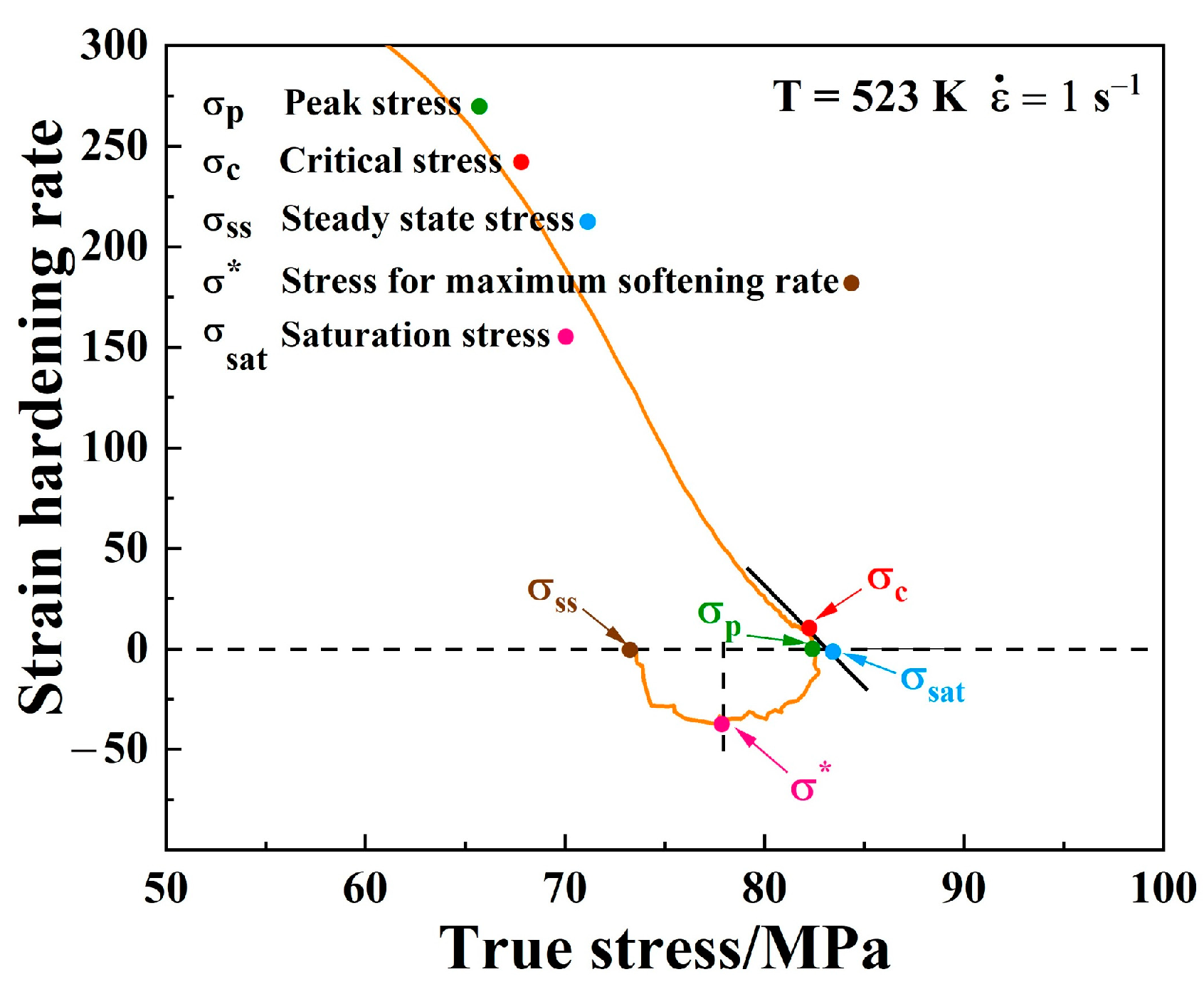
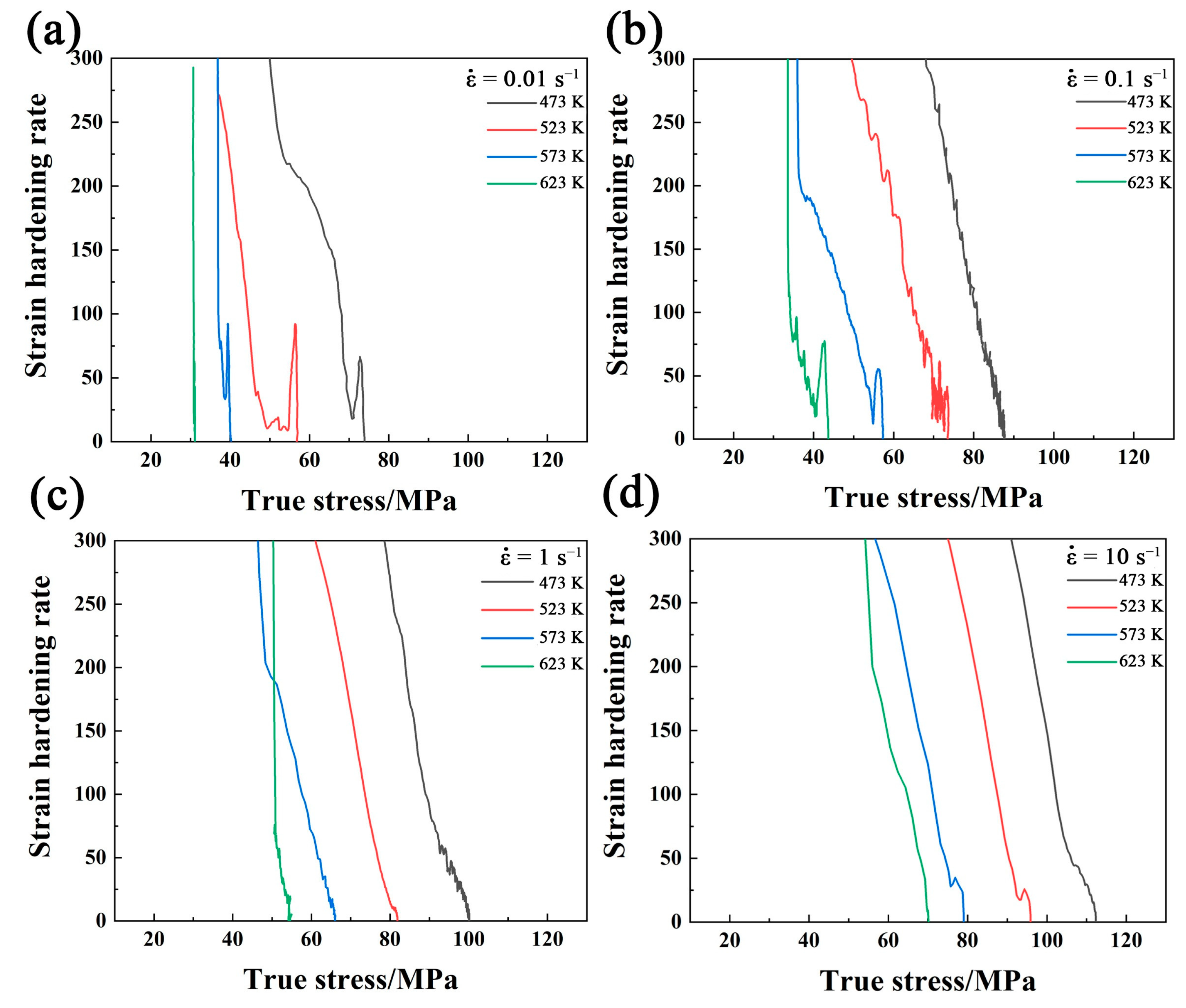
  • The true stress–strain curves of coarse grain Mg alloy showed typical DRX features. The addition of 3 wt.% Bi in pure Mg results in higher flow stress and a faster recrystallization under lower strain.
  • The constitutive equation of Mg-3Bi alloy was established, with average Q and n being 130.501 kJ/mol and 8.92. The constitutive equation for the hot deformation of the as-cast Mg-3Bi alloy is: ε ˙ = 2.64 × 10 11 [ sinh ( 0.0147 σ ) ] 9.11 exp ( 130500.95 R T ) .
  • The optimum hot deformation domains were also given, based on the processing maps. The range of the better stability domain was concentrated in 573 K/0.01 s−1–0.1 s−1 and 623 K/0.01 s−1. The DRX, more dependent on deformation temperature, and the kinetics were discussed.
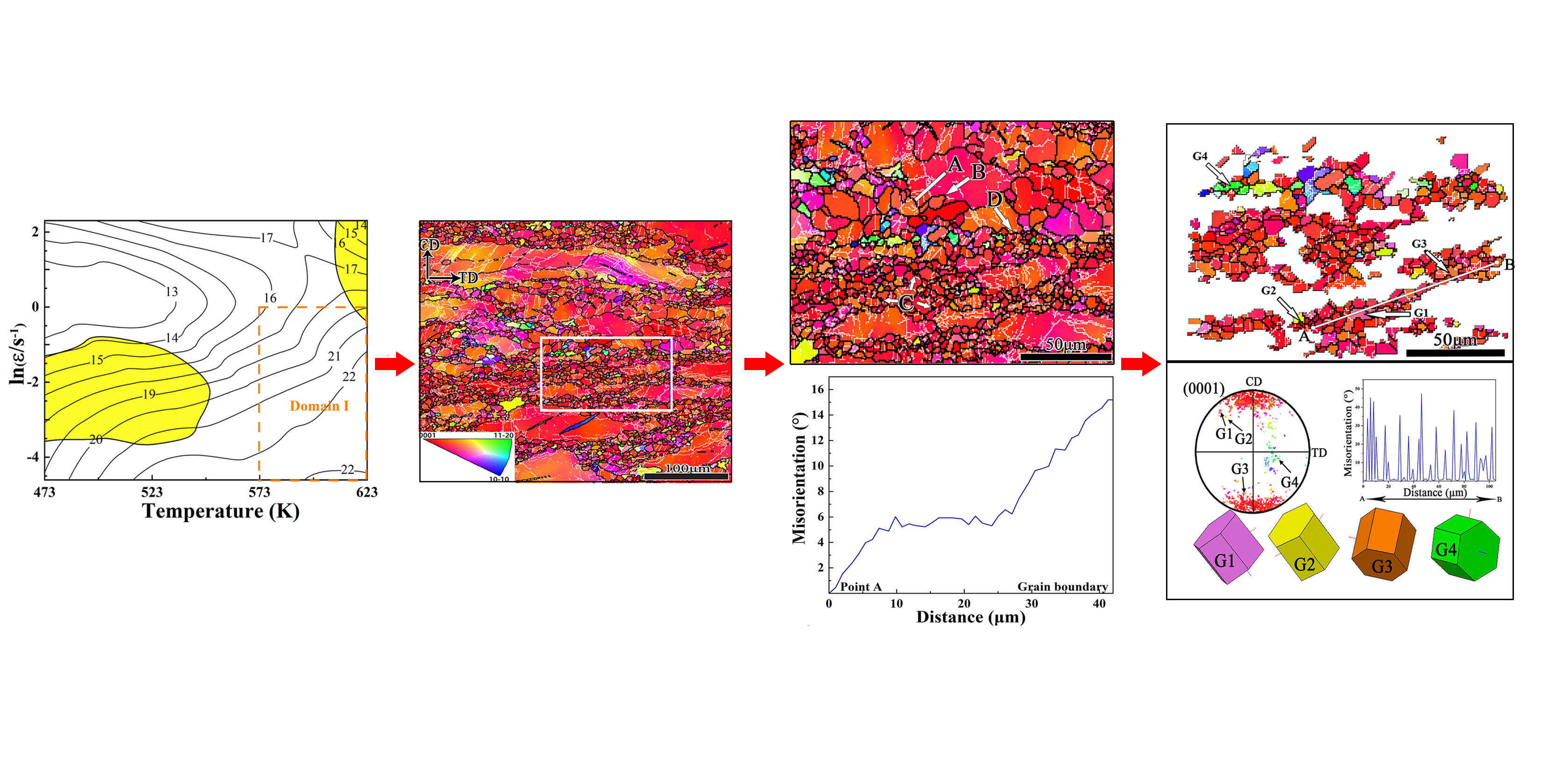
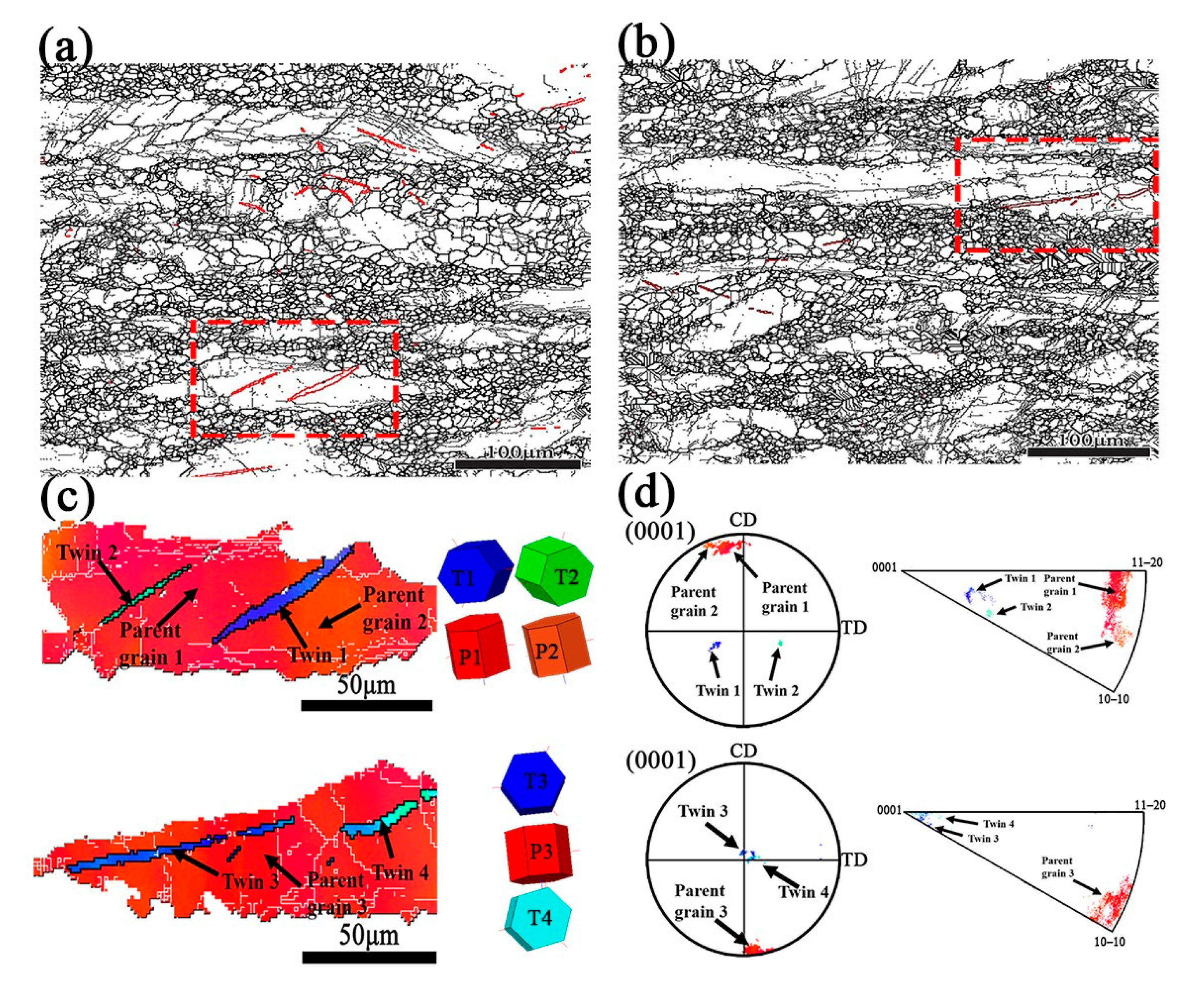
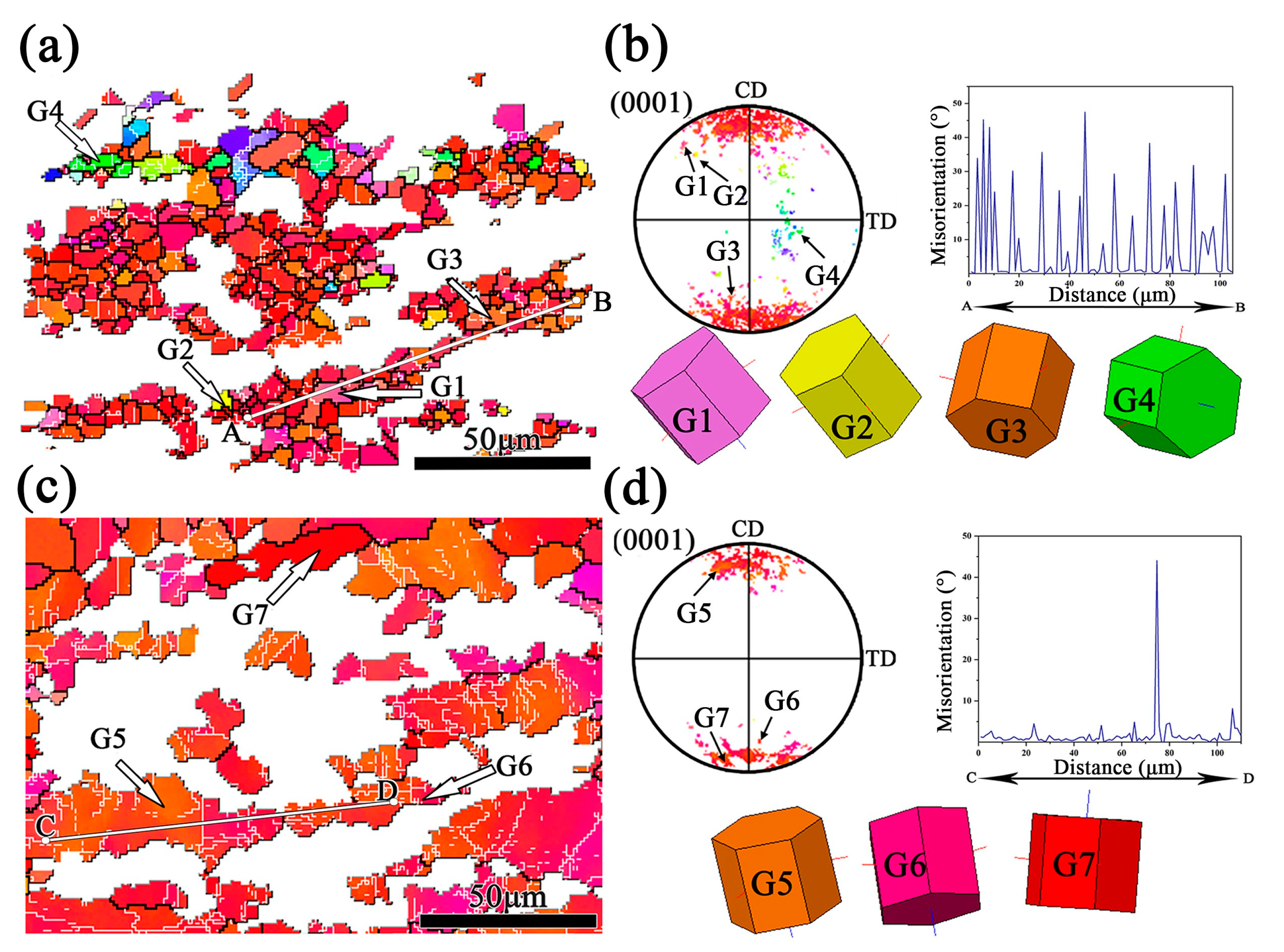
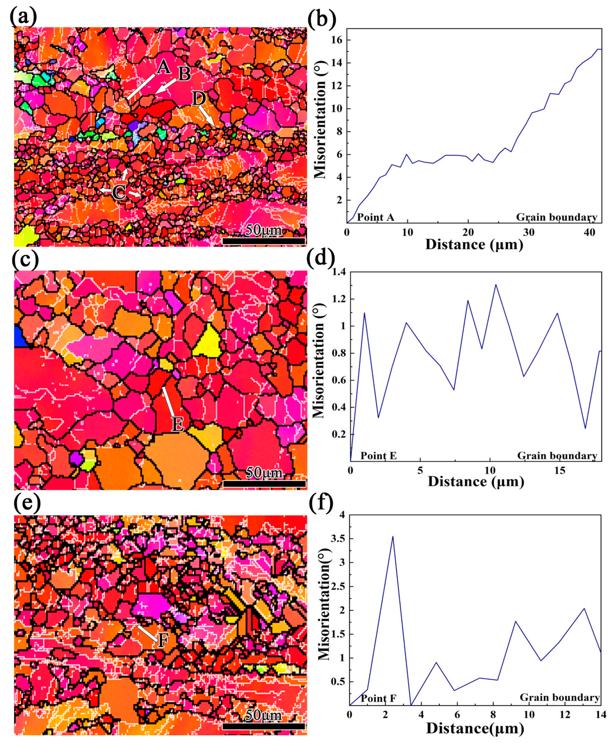
  • According to extensive EBSD analysis, CDRX and DDRX mechanisms occurred simultaneously at 573 K/0.01 s−1. The dominant mechanism changed to DDRX when the deformation temperature and strain rate increased in the Mg-3Bi alloy. The PSN effect also partially contributed to DRX of this RE-free Mg alloy.

Author Contributions

Conceptualization, H.Y. and H.L.; methodology, H.Y. and W.Y.; investigation, H.Y., H.L., B.J., J.M., X.C. and J.L.; resources, S.K., W.C., S.P., D.C., J.M., X.C. and J.L.; writing—original draft preparation, H.Y. and H.L.; writing—review and editing, H.Y., H.L., B.J., W.Y., S.K., W.C., S.P., D.C., F.Y. and K.S.; supervision, S.K., S.P., F.Y., K.S., J.M., X.C. and J.L.; and project administration, H.Y. All authors have read and agreed to the published version of the manuscript.

Funding

The authors acknowledge financial support from the National Natural Science Foundation of China (51701060) and Tianjin city (18JCQNJC03900), the Scientific Research Foundation for the Returned Overseas Chinese Scholars of Hebei Province (C20190505), the 100 Foreign Experts Plan of Hebei Province (141100), the foundation of strengthening program (2019-JCJQ-142-00).

Conflicts of Interest

The authors declare no conflict of interest.

References

  1. Kulekci, M.K. Magnesium and its alloys applications in automotive industry. Int. J. Adv. Manuf. Technol. 2007, 39, 851–865. [Google Scholar] [CrossRef]
  2. Joost, W.J. Reducing Vehicle Weight and Improving U.S. Energy Efficiency Using Integrated Computational Materials Engineering. JOM 2012, 64, 1032–1038. [Google Scholar] [CrossRef] [Green Version]
  3. Wu, X.L.; Youssef, K.M.; Koch, C.C.; Mathaudhu, S.N.; Kecskés, L.J.; Zhu, Y.T. Deformation twinning in a nanocrystalline hcp Mg alloy. Scr. Mater. 2011, 64, 213–216. [Google Scholar] [CrossRef] [Green Version]
  4. Askariani, S.A.; Hasan Pishbin, S.M. Hot deformation behavior of Mg-4Li-1Al alloy via hot compression tests. J. Alloys Compd. 2016, 688, 1058–1065. [Google Scholar] [CrossRef]
  5. Hoseini-Athar, M.M.; Mahmudi, R.; Prasath Babu, R.; Hedström, P. Microstructural evolution and superplastic behavior of a fine-grained Mg–Gd alloy processed by constrained groove pressing. Mater. Sci. Eng. A 2019, 754, 390–399. [Google Scholar] [CrossRef]
  6. Nie, J.F.; Zhu, Y.M.; Liu, J.Z.; Fang, X.Y. Periodic segregation of solute atoms in fully coherent twin boundaries. Science 2013, 340, 957–960. [Google Scholar] [CrossRef] [PubMed]
  7. Pan, H.; Ren, Y.; Fu, H.; Zhao, H.; Wang, L.; Meng, X.; Qin, G. Recent developments in rare-earth free wrought magnesium alloys having high strength: A review. J. Alloys Compd. 2016, 663, 321–331. [Google Scholar] [CrossRef]
  8. Sasaki, T.T.; Ohkubo, T.; Hono, K. Precipitation hardenable Mg–Bi–Zn alloys with prismatic plate precipitates. Scr. Mater. 2009, 61, 72–75. [Google Scholar] [CrossRef]
  9. Zhou, D.W.; Liu, J.S.; Xu, S.H.; Peng, P. Thermal stability and elastic properties of Mg3Sb2 and Mg3Bi2 phases from first-principles calculations. Phys. B 2010, 405, 2863–2868. [Google Scholar] [CrossRef]
  10. Go, J.; Lee, J.U.; Yu, H.; Park, S.H. Influence of Bi addition on dynamic recrystallization and precipitation behaviors during hot extrusion of pure Mg. J. Mater. Sci. Technol. 2020, 44, 62–75. [Google Scholar] [CrossRef]
  11. Go, J.; Jin, S.-C.; Kim, H.; Yu, H.; Park, S.H. Novel Mg–Bi–Al alloy with extraordinary extrudability and high strength. J. Alloys Compd. 2020, 843, 156026. [Google Scholar] [CrossRef]
  12. Meng, S.J.; Yu, H.; Fan, S.D.; Kim, Y.M.; Park, S.H.; Zhao, W.M.; You, B.S.; Shin, K.S. A high-ductility extruded Mg-Bi-Ca alloy. Mater. Lett. 2020, 261, 127066. [Google Scholar] [CrossRef]
  13. He, C.; Zhang, Y.; Liu, C.Q.; Yue, Y.; Chen, H.W.; Nie, J.F. Unexpected partial dislocations within stacking faults in a cold deformed Mg−Bi alloy. Acta Mater. 2020, 188, 328–343. [Google Scholar] [CrossRef]
  14. He, C.; Li, Z.; Chen, H.; Wilson, N.; Nie, J.-F. Unusual solute segregation phenomenon in coherent twin boundaries. Nat. Commun. 2021, 12, 722. [Google Scholar] [CrossRef]
  15. Ion, S.E.; Humphreys, F.J.; White, S.H. Dynamic recrystallisation and the development of microstructure during the high temperature deformation of magnesium. Acta Metall. 1982, 30, 1909–1919. [Google Scholar] [CrossRef]
  16. Hoseini-Athar, M.M.; Mahmudi, R. Effect of Zn content on hot deformation behavior of extruded Mg–Gd–Zn alloys. Mater. Sci. Eng. A 2019, 759, 745–753. [Google Scholar] [CrossRef]
  17. Meng, S.; Yu, H.; Li, L.; Qin, J.; Woo, S.K.; Go, Y.; Kim, Y.M.; Park, S.H.; Zhao, W.; Yin, F.; et al. Effects of Ca addition on the microstructures and mechanical properties of as-extruded Mg–Bi alloys. J. Alloys Compd. 2020, 834, 155216. [Google Scholar] [CrossRef]
  18. Ali, Y.; Qiu, D.; Jiang, B.; Pan, F.; Zhang, M.-X. Current research progress in grain refinement of cast magnesium alloys: A review article. J. Alloys Compd. 2015, 619, 639–651. [Google Scholar] [CrossRef]
  19. Yu, H.; Fan, S.; Meng, S.; Choi, J.O.; Li, Z.; Go, Y.; Kim, Y.M.; Zhao, W.; You, B.S.; Shin, K.S. Microstructural evolution and mechanical properties of binary Mg–xBi (x = 2, 5, and 8 wt%) alloys. J. Magnes. Alloys. 2020, 8, 959–967. [Google Scholar] [CrossRef]
  20. Yang, Y.; Peng, X.; Ren, F.; Wen, H.; Su, J.; Xie, W. Constitutive Modeling and Hot Deformation Behavior of Duplex Structured Mg–Li–Al–Sr Alloy. J. Mater. Sci. Technol. 2016, 32, 1289–1296. [Google Scholar] [CrossRef]
  21. Xia, X.; Chen, Q.; Huang, S.; Lin, J.; Hu, C.; Zhao, Z. Hot deformation behavior of extruded Mg–Zn–Y–Zr alloy. J. Alloys Compd. 2015, 644, 308–316. [Google Scholar] [CrossRef]
  22. Liu, S.; Pan, Q.; Li, M.; Wang, X.; He, X.; Li, X.; Peng, Z.; Lai, J. Microstructure evolution and physical-based diffusion constitutive analysis of Al-Mg-Si alloy during hot deformation. Mater. Des. 2019, 184, 108181. [Google Scholar] [CrossRef]
  23. Cheng, W.; Bai, Y.; Ma, S.; Wang, L.; Wang, H.; Yu, H. Hot deformation behavior and workability characteristic of a fine-grained Mg‒8Sn‒2Zn‒2Al alloy with processing map. J. Mater. Sci. Technol. 2019, 35, 1198–1209. [Google Scholar] [CrossRef]
  24. Zheng, T.; Li, D.; Zeng, X.; Ding, W. Hot compressive deformation behaviors of Mg–10Gd–3Y–0.5Zr alloy. Prog. Nat. Sci. Mater. Int. 2016, 26, 78–84. [Google Scholar] [CrossRef] [Green Version]
  25. Sellars, C.M.; Mctegart, W.J. On the mechanism of hot deformation. Acta Metall. 1966, 14, 1136–1138. [Google Scholar] [CrossRef]
  26. Cai, J.; Li, F.; Liu, T.; Chen, B.; He, M. Constitutive equations for elevated temperature flow stress of Ti–6Al–4V alloy considering the effect of strain. Mater. Des. 2011, 32, 1144–1151. [Google Scholar] [CrossRef]
  27. Lin, Y.C.; Chen, X.-M. A critical review of experimental results and constitutive descriptions for metals and alloys in hot working. Mater. Des. 2011, 32, 1733–1759. [Google Scholar] [CrossRef]
  28. McQueen, H.J.; Ryan, N.D. Constitutive analysis in hot working. Mater. Sci. Eng. A 2002, 322, 43–63. [Google Scholar] [CrossRef]
  29. Zhou, Z.; Fan, Q.; Xia, Z.; Hao, A.; Yang, W.; Ji, W.; Cao, H. Constitutive Relationship and Hot Processing Maps of Mg-Gd-Y-Nb-Zr Alloy. J. Mater. Sci. Technol. 2017, 33, 637–644. [Google Scholar] [CrossRef]
  30. Ansari, N.; Tran, B.; Poole, W.J.; Singh, S.S.; Krishnaswamy, H.; Jain, J. High temperature deformation behavior of Mg-5wt.%Y binary alloy: Constitutive analysis and processing maps. Mater. Sci. Eng. A 2020, 777, 139051. [Google Scholar] [CrossRef]
  31. Karami, M.; Mahmudi, R. Hot shear deformation constitutive analysis of an extruded Mg–6Li–1Zn alloy. Mater. Lett. 2012, 81, 235–238. [Google Scholar] [CrossRef]
  32. Svsn, M.; Bn, R. On the development of instability criteria during hotworking with reference to IN 718. Mater. Sci. Eng. A 1998, 254, 76–82. [Google Scholar] [CrossRef]
  33. Farabi, E.; Zarei-Hanzaki, A.; Abedi, H.R. Processing Map Development through Elaborating Phenomenological and Physical Constitutive Based Models. Adv. Eng. Mater. 2016, 18, 572–581. [Google Scholar] [CrossRef]
  34. Niu, Y.; Hou, J.; Ning, F.; Chen, X.; Jia, Y.; Le, Q. Hot deformation behavior and processing map of Mg-2Zn-1Al-0.2RE alloy. J. Rare Earths 2020, 38, 665–675. [Google Scholar] [CrossRef]
  35. Prasad, Y.V.R.K. Processing maps: A status report. J. Mater. Eng. Perform. 2003, 12, 638–645. [Google Scholar] [CrossRef]
  36. Tahreen, N.; Zhang, D.F.; Pan, F.S.; Jiang, X.Q.; Li, D.Y.; Chen, D.L. Hot deformation and processing map of an as-extruded Mg–Zn–Mn–Y alloy containing I and W phases. Mater. Des. 2015, 87, 245–255. [Google Scholar] [CrossRef]
  37. Samantaray, D.; Mandal, S.; Phaniraj, C.; Bhaduri, A.K. Flow behavior and microstructural evolution during hot deformation of AISI Type 316 L(N) austenitic stainless steel. Mater. Sci. Eng. A 2011, 528, 8565–8572. [Google Scholar] [CrossRef]
  38. Lv, B.-J.; Peng, J.; Wang, Y.-J.; An, X.-Q.; Zhong, L.-P.; Tang, A.-T.; Pan, F.-S. Dynamic recrystallization behavior and hot workability of Mg–2.0Zn–0.3Zr–0.9Y alloy by using hot compression test. Mater. Des. 2014, 53, 357–365. [Google Scholar] [CrossRef]
  39. Zhang, B.P.; Geng, L.; Huang, L.J.; Zhang, X.X.; Dong, C.C. Enhanced mechanical properties in fine-grained Mg–1.0Zn–0.5Ca alloys prepared by extrusion at different temperatures. Scr. Mater. 2010, 63, 1024–1027. [Google Scholar] [CrossRef]
  40. Cai, Z.; Chen, F.; Ma, F.; Guo, J. Dynamic recrystallization behavior and hot workability of AZ41M magnesium alloy during hot deformation. J. Alloys Compd. 2016, 670, 55–63. [Google Scholar] [CrossRef]
  41. Sadananda, K.; Marcinkowski, M.J. Mutual annihilation of unlike dislocations by cross slip in ordered and disordered alloys. J. Appl. Phys. 1973, 44, 4445–4454. [Google Scholar] [CrossRef]
  42. Jain, J.; Poole, W.J.; Sinclair, C.W.; Gharghouri, M.A. Reducing the tension–compression yield asymmetry in a Mg–8Al–0.5Zn alloy via precipitation. Scr. Mater. 2010, 62, 301–304. [Google Scholar] [CrossRef] [Green Version]
  43. Guan, D.; Rainforth, W.M.; Ma, L.; Wynne, B.; Gao, J. Twin recrystallization mechanisms and exceptional contribution to texture evolution during annealing in a magnesium alloy. Acta Mater. 2017, 126, 132–144. [Google Scholar] [CrossRef]
  44. Dudamell, N.V.; Ulacia, I.; Gálvez, F.; Yi, S.; Bohlen, J.; Letzig, D.; Hurtado, I.; Pérez-Prado, M.T. Twinning and grain subdivision during dynamic deformation of a Mg AZ31 sheet alloy at room temperature. Acta Mater. 2011, 59, 6949–6962. [Google Scholar] [CrossRef] [Green Version]
  45. McQueen, H.J. Development of dynamic recrystallization theory. Mater. Sci. Eng. A 2004, 387–389, 203–208. [Google Scholar] [CrossRef]
  46. Mwembela, A.; Konopleva, E.B. Microstructural development in Mg alloy AZ31 during hot working. Scr. Mater. 1997, 37, 1789–1795. [Google Scholar] [CrossRef]
  47. Jia, J.; Yang, Y.; Xu, Y.; Xu, B.; Luo, J.; Zhang, K. Microstructure evolution and dynamic recrystallization behavior of a powder metallurgy Ti-22Al-25Nb alloy during hot compression. Mater. Charact. 2017, 123, 198–206. [Google Scholar] [CrossRef]
Figure 1. OM micrographs of as-cast (a) pure Mg, (b) Mg-3Bi alloy, (c) SEM and corresponding EDS and (d) XRD pattern analysis of T4-treated Mg-3Bi alloy.
Metals 11 00838 g001
Figure 2. True stress−strain curves of pure Mg and Mg-3Bi alloy at various strain rates with temperature: (a) 473 K, (b) 523 K, (c) 573 K, and (d) 623 K.
Metals 11 00838 g002
Figure 3. The shape of the true stress−strain curve and the relationship between different deformation.
Metals 11 00838 g003
Figure 4. Peak stress of Mg-3Bi alloy under different deformation conditions.
Metals 11 00838 g004
Figure 5. The linear relationship fitting between (a) ln ε ˙ - ln σ , (b) ln ε ˙ - σ , (c) ln ε ˙ - ln [ sinh ( α σ ) ] and (d) ln sinh ( α σ ) - 1000 / T , respectively.
Metals 11 00838 g005
Figure 6. Relationship between peak stress and Zener−Hollomon parameter.
Metals 11 00838 g006
Figure 7. The 3D response surface of m-value on strain rate and temperature under different strains: (a) ε   = 0.1, (b) ε = 0.3, (c) ε   = 0.5, (d) ε   = 0.8, respectively.
Metals 11 00838 g007
Figure 8. The processing maps of Mg-3Bi alloy at different strains: (a) ε = 0.1, (b) ε   = 0.3, (c) ε   = 0.5, (d) ε   = 0.8.
Metals 11 00838 g008
Figure 9. Schematic diagram of the relationship between Θ and σ at 523 K and 1 s−1 in Mg-3Bi alloy.
Metals 11 00838 g009
Figure 10. The plots of work hardening rate (Θ) against flow stress (σ) of Mg-3Bi alloy with different temperatures upon strain rates of (a) 0.01 s−1, (b) 0.1 s−1, (c) 1 s−1, (d) 10 s−1.
Metals 11 00838 g010
Figure 11. The plots of the derivative of Θ with respect to σ against flow stress (σ) for Mg-3Bi alloy.
Metals 11 00838 g011
Figure 12. The linear relationship between (a) σp and σc, (b) εp and εc.
Metals 11 00838 g012
Figure 13. Vf of DRX at different temperatures with strain rates (a) ε   ˙ = 0.01 s−1; (b) ε   ˙ = 0.1 s−1; (c) ε   ˙ = 1 s−1; (d) ε ˙   = 10 s−1.
Metals 11 00838 g013
Figure 14. Inverse pole figures and misorientation angle distribution maps of Mg-3Bi alloy under specific conditions (a,b) 573 K and 0.01 s−1, (c,d) 623 K and 0.01 s−1, (e,f) 573 K and 0.1 s−1, respectively.
Metals 11 00838 g014
Figure 15. Pole figures of Mg-3Bi alloy at various deformation conditions: (a) 573 K and 0.01 s−1, (b) 623 K and 0.01 s−1, (c) 573 K and 0.1 s−1.
Metals 11 00838 g015
Figure 16. Grain boundary maps showing twinning under 573 K with strain rate (a) 0.01 s−1, (b) 0.1 s−1, (c) intercept region about crystal orientation in (a,b,d) corresponding (0001) PFs and IPFs in (c), respectively.
Metals 11 00838 g016
Figure 17. IPF maps of Mg-3Bi alloy at 573 K and 0.01 s−1 exhibited: (a,b) recrystallized grains, corresponding PF and misorientation profiles with crystal orientation along the line marked AB, (c,d) coarse grains, corresponding PF and misorientation profiles with crystal orientation along the line marked CD, respectively.
Metals 11 00838 g017
Figure 18. The EBSD diagrams and misorientation profiles along the line marked of Mg-3Bi alloy under different conditions: (a,b) 573 K and 0.01 s−1, (c,d) 623 K, and 0.01 s−1, (e,f) 573 K and 0.1 s−1, respectively.
Metals 11 00838 g018
Figure 19. Schmid factor analysis in terms of various deformation mechanisms in Mg-3Bi alloy compressed under different conditions: (a) 573 K and 0.01 s−1, (b) 623 K and 0.01 s−1, (c) 573 K and 0.1 s−1.
Metals 11 00838 g019
Publisher’s Note: MDPI stays neutral with regard to jurisdictional claims in published maps and institutional affiliations.

