Article

Microstructural Evolution along the NiCrMoV Steel Welded Joints Induced by Low-Cycle Fatigue Damage

1
School of Mechanical Engineering, University of Shanghai for Science and Technology, Shanghai 200093, China
2
Machinery Industry Key Laboratory for Mechanical Strength and Reliability Evaluation of Auto Chassis Components, University of Shanghai for Science and Technology, Shanghai 200093, China
3
Shanghai Technology Service Platform of Reliability Evaluation for New Energy Vehicle, Shanghai 200093, China
4
School of Mechanical and Power Engineering, East China University of Science and Technology, Shanghai 200237, China
*
Authors to whom correspondence should be addressed.
Metals 2021, 11(5), 811; https://doi.org/10.3390/met11050811
Submission received: 20 April 2021 / Revised: 11 May 2021 / Accepted: 14 May 2021 / Published: 16 May 2021
(This article belongs to the Special Issue Fatigue Design of Steel and Composite Structures)

Abstract

:
The degradation of mechanical properties of materials is essentially related to microstructural changes under service loadings, while the inhomogeneous degradation behaviors along welded joints are not well understood. In the present work, microstructural evolution under low-cycle fatigue in base metal (BM) and weld metal (WM) of NiCrMoV steel welded joints were investigated by miniature tensile tests and microstructural observations. Results showed that both the yield strength and ultimate tensile strength of the BM and WM decreased after low-cycle fatigue tests, which were attributed to the reduction of dislocation density and formation of low-energy structures. However, the microstructural evolution mechanisms in BM and WM under the same cyclic loadings were different, i.e., the decrease of dislocation density in BM was attributed to the dislocation pile-ups along the grain boundaries, dislocation tangles around the carbides at the lower strain amplitudes (±0.3% or ±0.5%). Additionally, when the strain amplitude was ±8%, the dislocation density was further decreased by the formation of subgrains in BM. For WM, the dislocation density decreased with the increase of strain amplitude, which was mainly caused by the dislocation pile-ups along the grain boundaries and the formation of subgrains.

1. Introduction

With the increasing requirements of high efficiency, high reliability and accurate application, the structure design based on the physical properties of the as-received materials become inopportune since the mechanical properties and microstructures of materials would be changed by the combined influence of environment and loadings in service, especially for the engineering materials used in the field of high temperature, large loadings or harsh environments [1,2,3,4,5].
Focused on the microstructural evolutions of martensitic or bainitic steels, some previous papers have revealed that the microstructures obviously changed with the cyclic softening (CS) in the martensitic or bainitic steels during low-cycle fatigue (LCF) tests [6,7,8,9,10,11]. The decreasing rate of CS of martensitic steels at the initial stage in LCF tests was much higher than in the latter stage [12,13,14,15,16]. Kim et al. [17] found that CS was caused by the decrease of dislocation density due to the formation of dislocation cells, the increasing width of martensitic laths and the variation of the slip system. Mishnev et al. [18] reported that the higher rate of CS in the initial stage was attributed to dislocation arrangement with the interaction between as-received dislocations and newly generated dislocations in martensitic laths, but the CS in the latter stage decreased relatively slowly due to the lath boundaries pinned by the carbide precipitates. In addition, Roldán et al. [19] studied the effect of LCF damage on the microstructural modifications of martensitic steels with the strain amplitude from 0.4%–1.8% and discovered that the changes of dislocations and subgrain structures were more intense with the increase of the strain amplitude.
As described above, both the CS in martensites and bainites were closely correlated with the decrease of dislocation density, the formation of low-energy structures and the interaction between dislocations and carbide precipitates during the LCF deformation process [10,11,20]. However, the differences of microstructural evolution mechanisms in martensitic and bainitic laths under the same cyclic loadings have not been well understood. To investigate the difference in microstructural changes in martensites and bainites, miniature tensile tests and microstructural observations by transmission electron microscopy (TEM) were carried out before and after LCF tests with different strain amplitudes at room temperature.

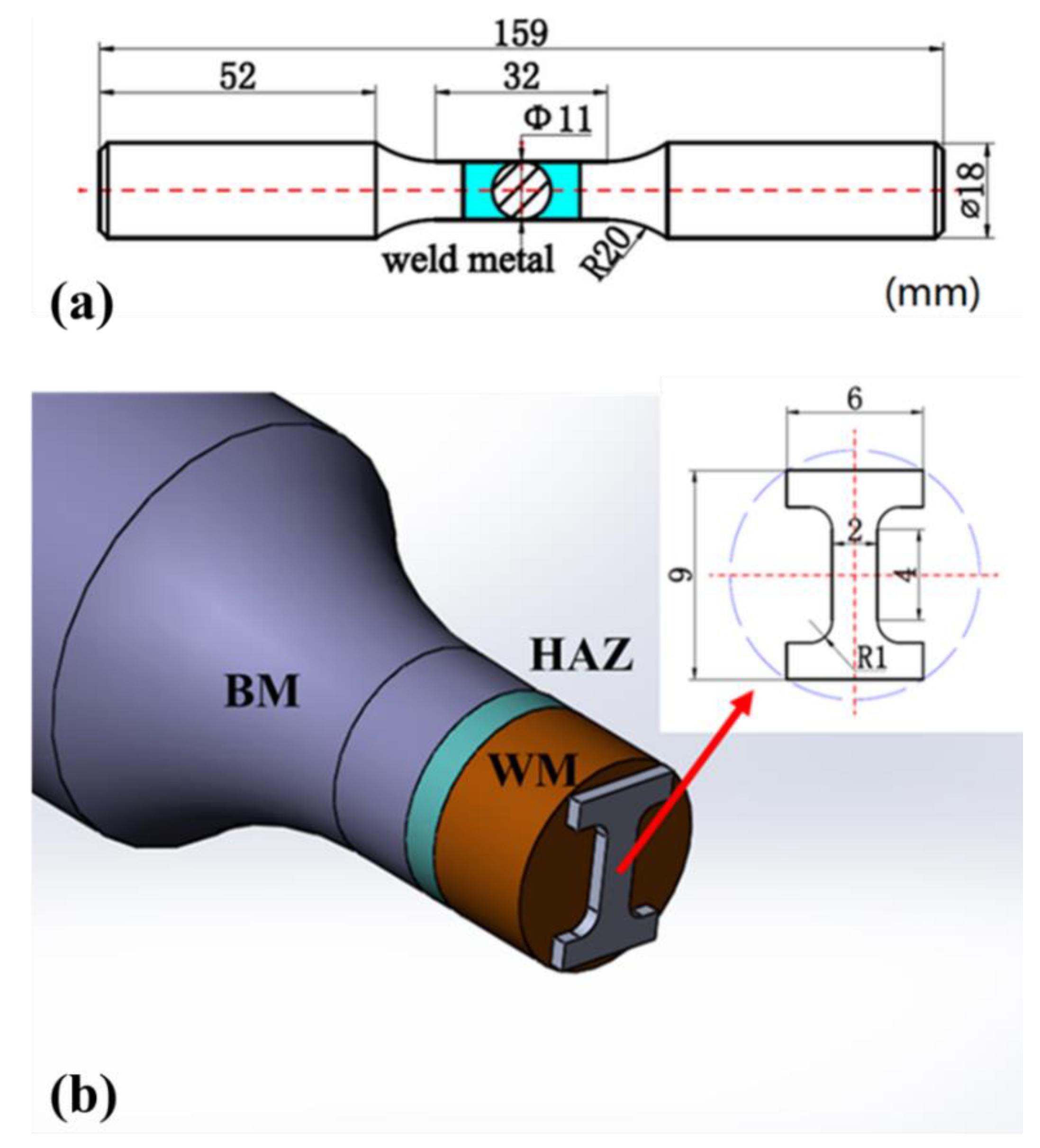
2. Materials and Methods

The studied materials in the present work were NiCrMoV steel welded joints, which were welded together by narrow gap submerged arc welding technique. The chemical elements of base metals (BM) and weld metals (WM) were listed in Table 1. The microstructures in the different zones were investigated by optical microscopy (OM, SEISS Axio Observer A1m, Braunschweig, German) and scanning electron microscopy (SEM, ZEISS EVO MA15, Braunschweig, German). As shown in Figure 1a,b, BM mainly consisted of large blocky tempered lathy martensites and a small amount of granular tempered bainites. A large number of needle-like bainites with some δ-ferrites distributed parallelly on the matrix in WM (Figure 1c,d).
To investigate the microstructural evolutions induced by LCF damage, the strain-controlled LCF tests were carried out by the fatigue device (INSTRON) under the triangular strain wave with the strain ratio of −1 and the strain amplitude of ±0.3%, ±0.5% and ±0.8%, respectively, at a constant strain rate of 0.008 s−1. The fatigue tests were stopped at the point (regarded the fatigue life, Nf) when the maximum cyclic stress was reduced to half of the maximum initial tensile stress. The detailed sizes of LCF specimens were shown in Figure 2a. After LCF tests, microstructural observations by transmission electron microscopy (TEM, JEM-2100, JEOL, Japan) and miniature tensile tests were performed with the specimens cut from BM and WM in the LCF damaged welded joints. The tensile tests were carried out by the in-situ tensile machine ( Tansi, Deben, UK) with the specimens cut from BM and WM, respectively (Figure 2b), and the tensile rate was 0.01 mm/s. In addition, the hardness measurements were performed by the microhardness tester (WHVS-1000, Hongce Yiqi, Shanghai, China) in BM and WM by the maximum load of 1.96 N with a holding time of 15 s.

3. Results and Discussion

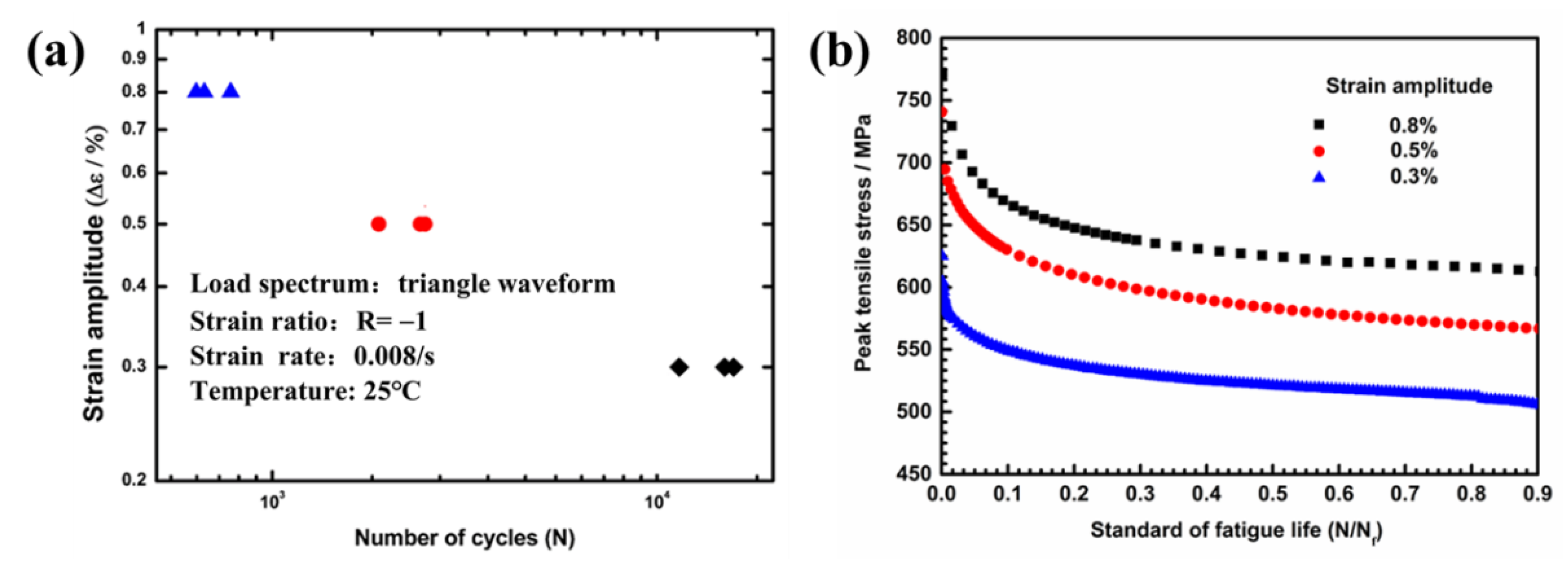
3.1. The Low-Cycle Fatigue Tests
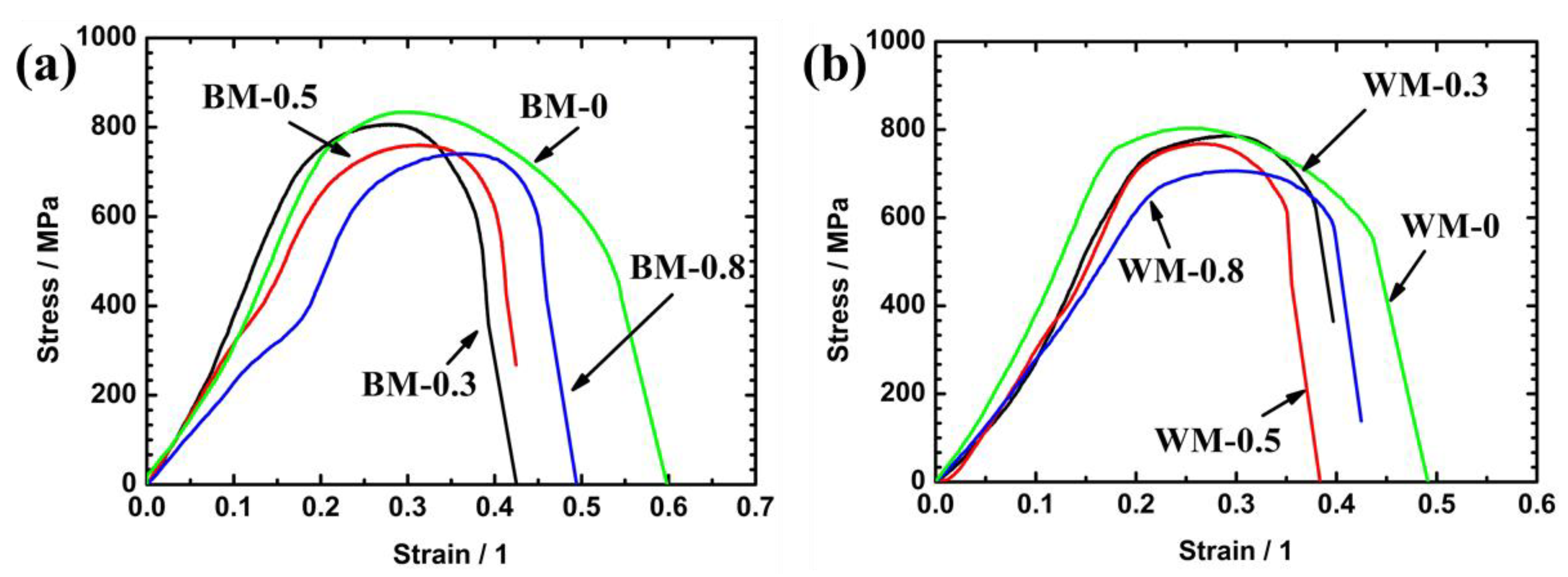
The relation between strain amplitude and fatigue life was displayed in Figure 3b, which showed that the fatigue life decreased with the increase of strain amplitude. The normalized fatigue life (n) was defined as the ratio of the number of current cycles (N) and the number of cycles to failure (Nf). As shown in Figure 3b, the cyclic peak stress decreased with the increase of the standard fatigue life for each strain amplitude, which indicated that CS took place in the specimens during the LCF tests. At the initiation stage of the LCF test (n ≤ 0.1), the cyclic peak stress decreased quickly with a relatively higher rate. Then, the slope of cyclic peak stress slowed down obviously with the increase of standard fatigue life (n ≥ 0.1).

3.2. Tensile Tests

The tensile curves of the LCF damaged BM and WM were shown in Figure 4a,b, respectively. Additionally, the yield strength (YS) and ultimate tensile strength (UTS) acquired from the tensile curves were listed in Table 2. It was clear to see that both the YS and UTS decreased after the LCF tests, and the reduction of YS and UTS decreased with the increase of strain amplitude, which also suggested that the tensile strengths of BM and WM were reduced by LCF damage.

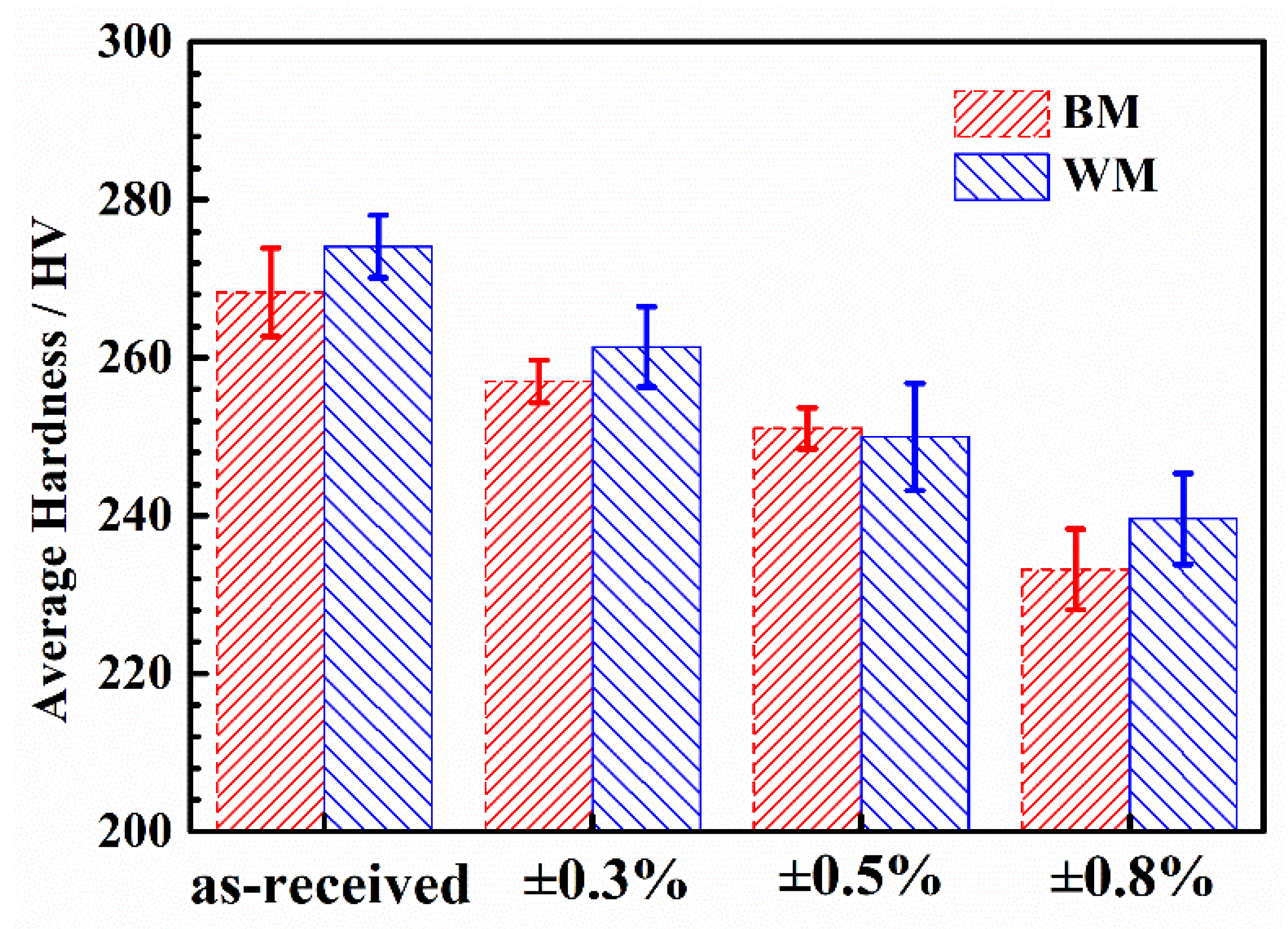
3.3. Hardness Measurements

To study the effect of LCF damage on hardness, the hardness measurement was carried out before and after LCF tests. Figure 5 showed the average hardness value of the as-received and LCF damaged BM and WM with different strain amplitudes. Compared to the as-received samples, both the average hardness values of the LCF-damaged BM and WM were reduced distinctly, which indicated that both the reductions of BM’s and WM’s hardness were induced by LCF damage. Additionally, the reduction of hardness increased with the increase of applied strain amplitude.

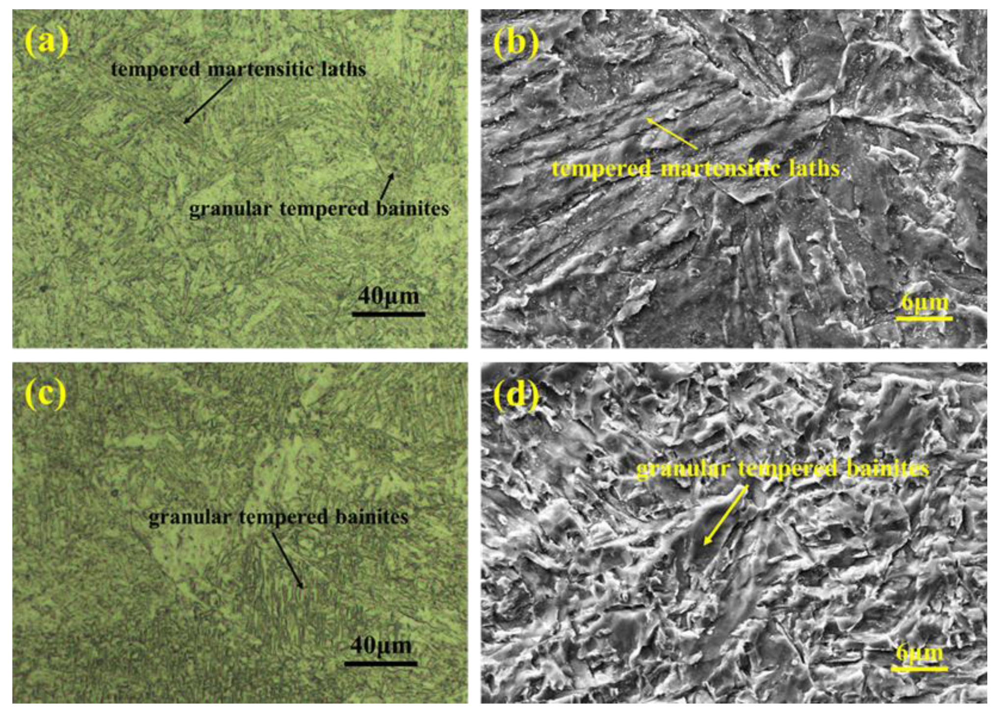
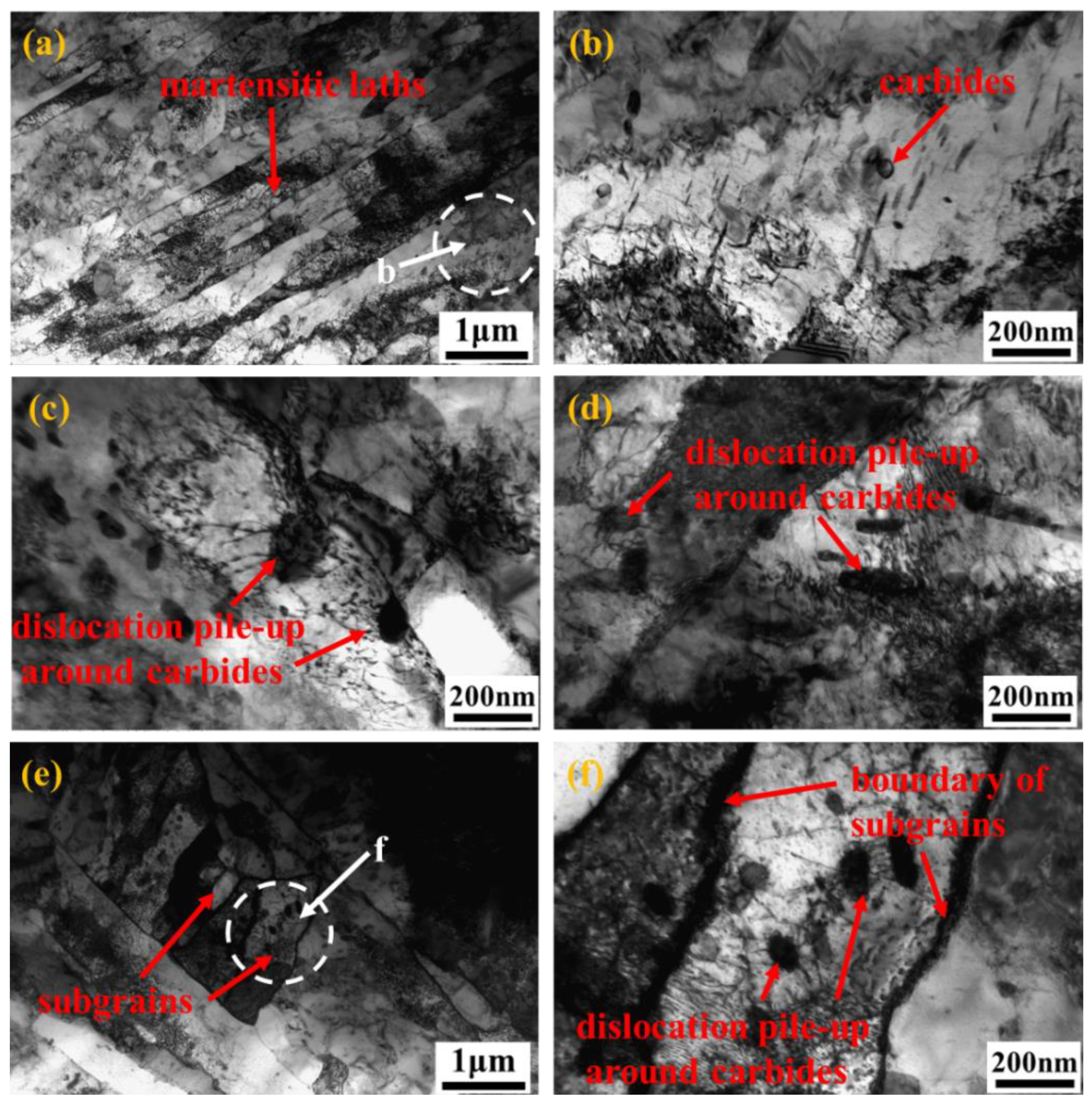
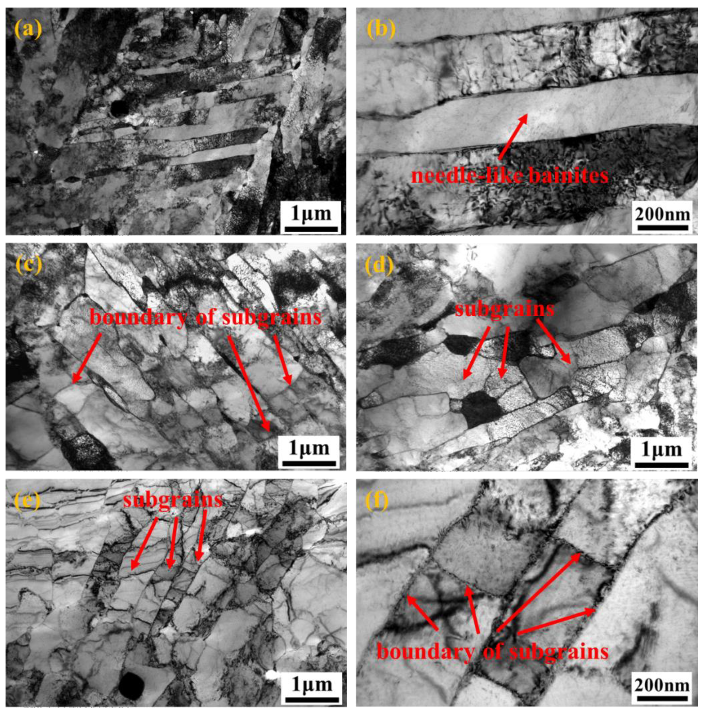
3.4. Microstructural Observation by TEM

Figure 6 showed the typical TEM microstructures in the as-received and LCF damaged BM. As displayed in Figure 6a,b, the lathy martensites in a block with some carbide precipitates distributed parallelly in the as-received BM, and a large amount of dislocations tangling each other located in a part of martensitic laths. Compared to the as-received specimens, the dislocation density decreased distinctly in the martensitic lath after the LCF tests with the strain amplitudes of ±0.3% and ±0.5% (Figure 6c,d). Meanwhile, dislocation pile-ups were formed around the carbide precipitates in the lathes or along the boundary of lathes (Figure 6c,d), especially the dislocations stacked obviously around the carbides, which were attributed to that carbide precipitates retarded the dislocation movements during cyclic loading processes. In addition, few spindly martensitic laths were incorporated together due to the annihilation of the low-angle boundary. This led to an increase in the width of some martensitic laths. When the strain amplitude grew to ±0.8%, subgrains were formed in the wider martensitic laths with the further reduction of dislocation density. Additionally, in this condition, the dislocation density along the boundaries of subgrains was higher than that of the martensitic laths in the as-received specimens, which indicated that the dislocation in the laths might move into the subgrains under the interaction of cyclic deformation.
Figure 7 showed the typical TEM microstructures in the as-received and LCF damaged WM. As displayed in Figure 7a,b, the needle-like bainites without carbides located in the as-received WM and the dislocations of high density tangled each other in the localized zones of the bainites. After the LCF tests with the strain amplitude of ±0.3%, the dislocations in the LCF damaged WM decreased obviously and some dislocations were piled up along the boundaries of bainites, which were similar to the LCF damaged BM. Few subgrains appeared in the wider bainites under the strain amplitude of ±0.3%, but no subgrains were observed in the LCF damaged BM. With the strain amplitude increasing from ±0.3% to ±0.8%, except for the distinct reduction of dislocation density, more and more subgrains were formed in the bainites, and even more, some subgrains also distributed in the narrower needle-like bainites (Figure 7). This means that the microstructural evolutions of martensites and bainites were different under the same applied cyclic loadings.

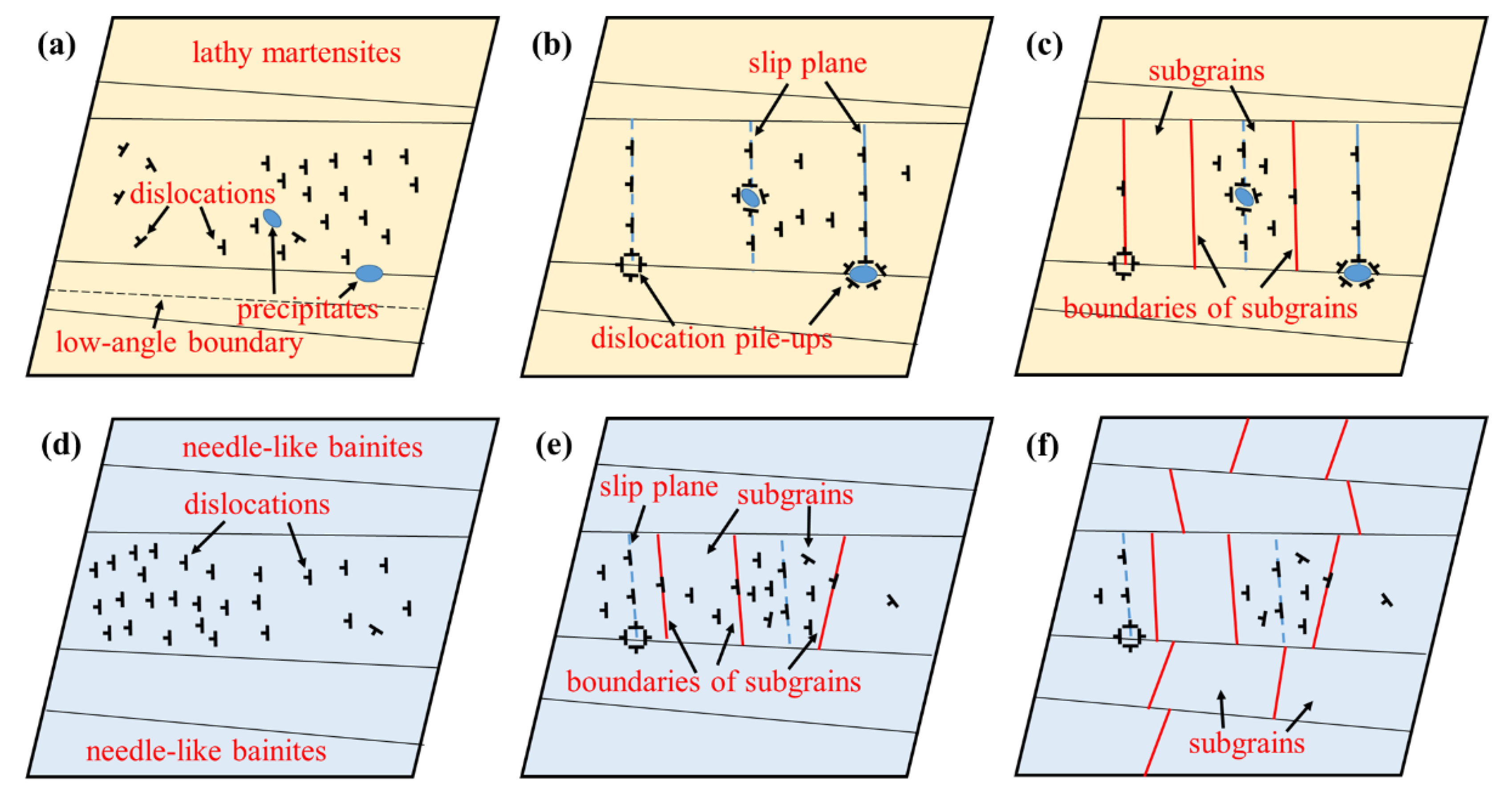
3.5. The Difference of Cyclic Softening Mechanisms in BM and WM

The CS phenomenon took place in the welded joints of the NiCrMoV steels during the LCF tests under different strain amplitudes, which was reflected obviously by the evolution of cyclic peak tensile stress (Figure 3b). Furthermore, the results of tensile tests revealed that both the YS and UTS of BM and WM decreased due to the low-cycle fatigue damage (Figure 4). The typical TEM microstructural observation of the low-cycle fatigue damaged specimens with various strain amplitudes displayed that the microstructural evolutions in BM and WM were different due to the diversity of microstructural distribution (Figure 6 and Figure 7). As described in the previous studies [21,22,23,24], CS of the lathy martensites was attributed to the reduction of dislocation density induced by the LCF damage, which was also observed in the present work. With the increase of strain amplitude, the dislocation density in the lathy martensites or needle-like bainites both decreased distinctly (Figure 6 and Figure 7).
The microstructural evolution mechanisms for martensites and bainites with different strain amplitudes were shown in Figure 8. Under the action of stable cyclic loading, the dislocations moved back and forth as if a shuttle along the slip plane between the two dislocation walls (Figure 8b,e). When the tensile stress was the maximum, the mobile dislocations piled up against one dislocation wall while the opposite dislocation wall when the compressive stress was the maximum. The dislocation density remained relatively constant when the cyclic peak stress was stable since the generation and annihilation of free dislocation was balanced during this process. However, under the influence of cyclic plastic loading, the dislocations moved out of the slip plane and piled up at the grain boundaries with the annihilation of dislocations (Figure 8b,e), which led to the decrease of mobile dislocation.
Moreover, these were observed in the LCF damaged BM and WM under the strain amplitudes of ±0.3% or ±0.5% (Figure 6c,d and Figure 7c,d). When the strain amplitudes were relatively lower, there were two kinds of dislocation pile-ups distributing in the lathy martensites: one was piling up against the boundaries of the martensitic laths, another was tangling around the carbide precipitates. The pile-ups along the boundaries were formed due to the dislocation congestion at the end of the slip plane. In addition, the formation of pile-ups around the carbides was attributed to the mobile dislocations hindered by the carbides during the cyclic movement and tangled around the carbides. However, there was only one kind of dislocation pile-up distributing in the needle-like bainites—the dislocation pile-ups along the boundaries of bainites. In addition, under the strain amplitude of ±0.3%, few subgrains were formed in the wider needle-like bainites after LCF tests, but no subgrains were observed in the lathy martensites. This indicated that compared to lathy martensites, needle-like bainites have been preferentially decomposed into subgrains under the same cyclic loading, which implied that the capability of resisting deformation of needle-like bainites was lower than that of lathy martensites. This was caused by that the strain hardening capacity of bainitic microstructures was weaker than that of the lathy martensites [25,26,27]. Meanwhile, the slightly increasing width of some lathy martensites was induced by the annihilation of low-angle boundaries, but no increase of the width of needle-like bainites [28]. Some mobile dislocation moved into the subgrains, which led to that the dislocation density in some subgrains was higher than that in the as-received bainites.
When the strain amplitude was ±0.8%, the dislocation density further decreased in the lathy martensites and needle-like bainites. Few subgrains were formed in the wider martensitic laths (Figure 6e and Figure 8c), which was similar to the needle-like bainites. However, for bainites, the number of grains increased distinctly with the strain amplitude from ±0.3% to ±0.8%, and even the narrower bainitic laths have been decomposed into subgrains when the strain amplitude was ±0.8% (Figure 7e and Figure 8f).
According to the Bailey–Hirsh relation [29,30], the YS of metallic materials was linear to the square root of dislocation density, i.e., YS increased with the growth of dislocation density. In the present work, it was as described above that the reduction mechanisms of dislocation density in BM and WM were different, but the YSs of both the BM and the WM decreased obviously due to the LCF damage (Figure 4). Meanwhile, the UTSs of both BM and WM were also reduced distinctly after LCF tests (Figure 4), which indicated that the decrease of both the YS and UTS were in correlation with the reduction of dislocation density induced by the LCF damage. In addition, the evolution of peak cyclic stress indicated that the reduction of dislocation density decreased much quicker at the initiation of LCF tests (n ≤ 0.1) than that of the stable period (0.1 ≤ n ≤ 0.8). This was also reported systematically by Giordana et al. [21], who studied the microstructural evolution of martensitic steel induced by LCF damage with the strain amplitude of ±0.2% at room temperature. They revealed that the free dislocation density was dropped from 2.4 × 10¹⁴/m2 to 1 × 10¹⁴/m2 at the cyclic cycles of 500 cycles and to 0.5 × 10¹⁴/m2 at 11,000 cycles. In addition, Guguloth et al. [31] also found that the average dislocation density of the damaged specimens reduced to less than 1/3 of the as-received specimen after LCF test with the strain amplitude of ±1% at room temperature. It was well demonstrated by these quantitative results that cyclic softening took place in martensitic steels with the reduction of the dislocation density when the cyclic cycles increased in the LCF tests, which led to the decrease of YS and UTS in BM. Although the microstructural evolution mechanisms in BM and WM were different, subgrains were formed in WM with the decrease of dislocation density, which also made the YS and UTS reduced by the LCF damage.

4. Conclusions

As a summary, the differences of the microstructural evolution mechanisms of the lathy martensites in BM and the needle-like bainites in WM induced by LCF damage have been investigated through LCF tests, tensile tests and microstructural observations. Results showed that cyclic softening took place in BM and WM under different strain amplitudes. Both the YS and UTS of BM and WM decreased with the increase of strain amplitude after LCF tests, and the LCF damages in them were reflected by different microstructural evolutions. The decrease of dislocation density in BM was attributed to the dislocation pile-ups along the grain boundaries, dislocation tangles around the carbides at the lower strain amplitudes (±0.3% or ±0.5%) and the annihilation of low-angle grain boundaries. When the strain amplitude was ±8%, the dislocation density was further decreased by the formation of subgrains in BM. For WM, the dislocation density decreased with the increase of strain amplitude, which was mainly caused by the dislocation pile-ups along the grain boundaries and the formation of subgrains.

Author Contributions

Methodology, validation, formal analysis and investigation S.W.; resources, S.W. and Y.H.; data curation, M.Z.; writing—original draft preparation, S.W., Y.H., M.Z. and F.X.; project administration, F.X.; funding acquisition, S.W. and Y.H. All authors have read and agreed to the published version of the manuscript.

Funding

The work was sponsored by the National Natural Science Foundation of China (Grant No. 51875202 and 52005336), Shanghai Sailing Program (19YF1434400) and China Postdoctoral Science Foundation (2020M671167).

Institutional Review Board Statement

Not applicable.

Informed Consent Statement

Not applicable.

Data Availability Statement

The data will be gotten from the corresponding authors if the request is reasonable.

Conflicts of Interest

The authors declare that they have no known competing financial interests or personal relationships that could have appeared to influence the work reported in this paper.

References

  1. Shao, C.; Zhang, P.; Zhang, Z.; Zhang, Z. Butterfly effect in low-cycle fatigue: Importance of microscopic damage mechanism. Scr. Mater. 2017, 140, 76–81. [Google Scholar] [CrossRef]
  2. Du, C.C.; Hoefnagels, J.J.; Vaes, R.R.; Geers, M.M. Plasticity of lath martensite by sliding of substructure boundaries. Scr. Mater. 2016, 120, 37–40. [Google Scholar] [CrossRef]
  3. Xue, P.; Wang, B.; An, X.; Ni, D.; Xiao, B.; Ma, Z. Improved cyclic softening behavior of ultrafine-grained Cu with high microstructural stability. Scr. Mater. 2019, 166, 10–14. [Google Scholar] [CrossRef]
  4. Höppel, H.W.; Zhou, Z.M.; Mughrabi, H.; Valiev, R.Z. Microstructural study of the parameters governing coarsening and cyclic softening in fatigued ultrafine-grained copper. Philos. Mag. 2009, 82, 1781–1794. [Google Scholar] [CrossRef]
  5. Konovalov, S.; Komissarova, I.; Ivanov, Y.; Gromov, V.; Kosinov, D. Structural and phase changes under electropulse treatment of fatigue-loaded titanium alloy VT1-0. J. Mater. Res. Technol. 2019, 8, 1300–1307. [Google Scholar] [CrossRef]
  6. Konovalov, S.; Ivanov, Y.; Gromov, V.; Panchenko, I. Fatigue-Induced Evolution of AISI 310S Steel Microstructure after Electron Beam Treatment. Materials 2020, 13, 4567. [Google Scholar] [CrossRef] [PubMed]
  7. Hu, X.; Huang, L.; Wang, W.; Yang, Z.; Sha, W.; Wang, W.; Yan, W.; Shan, Y. Low cycle fatigue properties of CLAM steel at room temperature. Fusion Eng. Des. 2013, 88, 3050–3059. [Google Scholar] [CrossRef]
  8. Barrett, R.A.; O’Donoghue, P.E.; Leen, S.B. A physically-based constitutive model for high temperature microstructural deg-radation under cyclic deformation. Int. J. Fatigue 2017, 100, 388–406. [Google Scholar] [CrossRef] [Green Version]
  9. Stanford, N.; Wang, J.; Hilditch, T. Quantification of strain partitioning during low cycle fatigue of multi-phase steels con-taining a bainite matrix. Int. J. Fatigue 2019, 129, 105218. [Google Scholar] [CrossRef]
  10. Zhou, Q.; Qian, L.; Meng, J.; Zhao, L.; Zhang, F. Low-cycle fatigue behavior and microstructural evolution in a low-carbon carbide-free bainitic steel. Mater. Des. 2015, 85, 487–496. [Google Scholar] [CrossRef]
  11. Adamczyk-Cieślak, B.; Koralnik, M.; Kuziak, R.; Brynk, T.; Zygmunt, T.; Mizera, J. Low-cycle fatigue behaviour and micro-structural evolution of pearlitic and bainitic steels. Mater. Sci. Eng. A 2019, 747, 144–153. [Google Scholar] [CrossRef]
  12. Wang, C.; Xuan, F.-Z.; Zhao, P. A dislocation-based constitutive model for the cyclic response of nanolath strengthened steels. Int. J. Mech. Sci. 2019, 155, 475–487. [Google Scholar] [CrossRef]
  13. Zhao, P.; Xuan, F.-Z.; Wang, C. A physically-based model of cyclic responses for martensitic steels with the hierarchical lath structure under different loading modes. J. Mech. Phys. Solids 2019, 124, 555–576. [Google Scholar] [CrossRef]
  14. Zhao, P.; Xuan, F.-Z.; Wu, D.-L. Cyclic softening behaviors of modified 9–12%Cr steel under different loading modes: Role of loading levels. Int. J. Mech. Sci. 2017, 131-132, 278–285. [Google Scholar] [CrossRef]
  15. Shankar, V.; Valsan, M.; Rao, K.B.S.; Kannan, R.; Mannan, S.; Pathak, S. Low cycle fatigue behavior and microstructural evolution of modified 9Cr–1Mo ferritic steel. Mater. Sci. Eng. A 2006, 437, 413–422. [Google Scholar] [CrossRef]
  16. Zhang, Z.; Hu, Z.; Schmauder, S.; Zhang, B.; Wang, Z. Low cycle fatigue properties and microstructure of P92 ferrit-ic-martensitic steel at room temperature and 873 K. Mater. Charact. 2019, 157, 109923. [Google Scholar] [CrossRef]
  17. Kim, D.W.; Kim, S.S. Contribution of microstructure and slip system to cyclic softening of 9wt.%Cr steel. Int. J. Fatigue 2012, 36, 24–29. [Google Scholar] [CrossRef]
  18. Mishnev, R.; Dudova, N.; Kaibyshev, R. Effect of microstructural evolution on the cyclic softening of a 10% Cr martensitic steel under low cycle fatigue at 600 °C. Int. J. Fatigue 2020, 134, 105522. [Google Scholar] [CrossRef]
  19. Roldán, M.; Leon-Gutierrez, E.; Fernández, P.; Gómez-Herrero, A. Deformation behaviour and microstructural evolution of EUROFER97-2 under low cycle fatigue conditions. Mater. Charact. 2019, 158, 109943. [Google Scholar] [CrossRef]
  20. Wu, D.-L.; Xuan, F.-Z.; Guo, S.-J.; Zhao, P. Uniaxial mean stress relaxation of 9–12% Cr steel at high temperature: Experiments and viscoplastic constitutive modeling. Int. J. Plast. 2016, 77, 156–173. [Google Scholar] [CrossRef]
  21. Giordana, M.; Giroux, P.-F.; Alvarez-Armas, I.; Sauzay, M.; Armas, A.; Kruml, T. Microstructure evolution during cyclic tests on EUROFER 97 at room temperature. TEM observation and modelling. Mater. Sci. Eng. A 2012, 550, 103–111. [Google Scholar] [CrossRef]
  22. Hu, X.; Huang, L.; Yan, W.; Wang, W.; Sha, W.; Shan, Y.; Yang, K. Microstructure evolution in CLAM steel under low cycle fatigue. Mater. Sci. Eng. A 2014, 607, 356–359. [Google Scholar] [CrossRef] [Green Version]
  23. Fournier, B.; Sauzay, M.; Renault, A.; Barcelo, F.; Pineau, A. Microstructural evolutions and cyclic softening of 9%Cr marten-sitic steels. J. Nucl. Mater. 2009, 386–388, 71–74. [Google Scholar]
  24. Oh, Y.-J.; Ahiale, G.K.; Chun, Y.-B.; Cho, S.; Park, Y.-H.; Choi, W.-D.; Anderson, K.-H.E. Crystallographic evolution and cyclic softening behavior of reduced activation ferritic-martensitic steel under different fatigue modes. Mater. Sci. Eng. A 2021, 802, 140454. [Google Scholar] [CrossRef]
  25. Wang, D.-Q.; Zhu, M.-L.; Xuan, F.-Z. Correlation of local strain with microstructures around fusion zone of a Cr-Ni-Mo-V steel welded joint. Mater. Sci. Eng. A 2017, 685, 205–212. [Google Scholar] [CrossRef]
  26. Nambu, S.; Michiuchi, M.; Ishimoto, Y.; Asakura, K.; Inoue, J.; Koseki, T. Transition in deformation behavior of martensitic steel during large deformation under uniaxial tensile loading. Scr. Mater. 2009, 60, 221–224. [Google Scholar] [CrossRef]
  27. Na, H.; Nambu, S.; Ojima, M.; Inoue, J.; Koseki, T. Strain localization behavior in low-carbon martensitic steel during tensile deformation. Scr. Mater. 2013, 69, 793–796. [Google Scholar] [CrossRef]
  28. Sauzay, M.; Brillet, H.; Monnet, I.; Mottot, M.; Barcelo, F.; Fournier, B.; Pineau, A. Cyclically induced softening due to low-angle boundary annihilation in a martensitic steel. Mater. Sci. Eng. A 2005, 400-401, 241–244. [Google Scholar] [CrossRef]
  29. Bailey, J.E.; Hirsch, P.B. The dislocation distribution, flow stress, and stored energy in cold-worked polycrystalline silver. Philos. Mag. 1960, 5, 485–497. [Google Scholar] [CrossRef]
  30. Tanaka, Y.; Masumura, T.; Tsuchiyama, T.; Takaki, S. Effect of Dislocation Distribution on the Yield Stress in Ferritic Steel Under Identical Dislocation Density Conditions. SSRN Electron. J. 2019, 177, 176–180. [Google Scholar] [CrossRef]
  31. Guguloth, K.; Sivaprasad, S.; Chakrabarti, D.; Tarafder, S. Low-cyclic fatigue behavior of modified 9Cr–1Mo steel at elevated temperature. Mater. Sci. Eng. A 2014, 604, 196–206. [Google Scholar] [CrossRef]
Figure 1. The typical microstructures in different zones of welded joints observed by optical microscopy (OM) and scanning electron microscopy (SEM): base metal (a,b) and weld metal (c,d).
Metals 11 00811 g001
Figure 2. The detailed sizes of the specimens used in the low-cycle fatigue tests (a) and the detailed sizes of the miniature specimens used in the tensile tests (b).
Metals 11 00811 g002
Figure 3. The relationship of strain amplitude with fatigue life (a) and peak tensile stress with normalized fatigue life (b).
Metals 11 00811 g003
Figure 4. Tensile curves of as-received and low-cycle fatigue damaged specimens: BM (a) and WM (b).
Metals 11 00811 g004
Figure 5. The average hardness of the as-received and low-cycle fatigue damaged BM and WM with different strain amplitudes.
Metals 11 00811 g005
Figure 6. The typical TEM microstructures of the as-received and the LCF damaged BM specimens with different strain amplitudes: the as-received specimens (a), (b) was the local enlargement of (a), the LCF damaged specimens with the strain amplitude of ±0.3% (c), ±0.5% (d), ±0.8% (e), (f) was the local enlargement of (e).
Metals 11 00811 g006
Figure 7. The typical TEM microstructures of the as-received and the LCF damaged WM specimens with different strain amplitudes: the as-received specimens (a), (b) was the local enlargement in (a), the LCF damaged specimens with the strain amplitude of ±0.3% (c), ±0.5% (d), ±0.8% (e), (f) was the local enlargement in (e).
Metals 11 00811 g007
Figure 8. The schematic diagrams of the microstructural evolution mechanisms for martensites and bainites induced by LCF damage up to fracture: the as-received specimens (a), the LCF damaged specimens with the strain amplitudes of ±0.3% or ±0.5% (b) and ±0.8% (c) in BM; the as-received specimens (d), the damaged specimens with the strain amplitudes of ±0.3% or ±0.5% (e) and ±0.8% (f) in WM.
Metals 11 00811 g008
Table 1. The chemical compositions of base metals and weld metals (in wt.%).
ZoneCSiMnPSCrNiMoVCuFe
BM0.220.100.210.010.012.32.20.70.10.05Bal.
WM0.120.21.480.0050.0050.572.180.51--Bal.
Table 2. The yield strength (YS) and ultimate tensile strength (UTS) of BM and WM acquired from the tensile curves (MPa).
Strengths of Zonesas-Received±0.3%±0.5%±0.8%
YS of BM738.8 ± 12.2680.9 ± 11.6622.5 ± 15.3596.6 ± 12.1
YS of WM739.3 ± 14.4721.6 ± 13.2679.4 ± 14.3601.2 ± 12.6
UTS of BM837.5 ± 12.6806.8 ± 14.4760.8 ± 13.5740.8 ± 14.6
UTS of WM803.9 ± 10.5785.5 ± 11.3748.5 ± 12.1707.8 ± 10.6
Publisher’s Note: MDPI stays neutral with regard to jurisdictional claims in published maps and institutional affiliations.

