Abstract
Ti/Al multilayered composites (LMCs) with different layers were prepared by hot-pressing and hot-rolling. The effects of interface on the deep drawability of LMCs were explored. The results indicate that LMCs with more layers have a higher limit-drawing ratio (LDR) and exhibit an excellent deep drawability. The texture strength of the Ti layer gradually weakens with the increase of layers, which leads to the smaller yield ratio (σs/σb), the plastic strain ratio (r), and the larger strain hardening index (n), thus the deep drawability of LMCs with more layers is enhanced effectively. The Ti/Al interfaces in three, five, and seven layers of LMCs exhibit straight, small wave-like interlocking, and dense serrated structures at the corner of the cylindrical parts, respectively. The component metals become thinner with the increase of layers, and the increased interfacial pressure promotes the formation of an increasingly firm overlapped interfacial structure. The load transfer via the interfaces makes the stress distribution between layers more uniform with the increase of layers, which helps to coordinate deformation. Deflection and tearing occur when the cracks propagate to the interface due to the complex stress state, which hinders and delays the crack penetration, thereby improving the deep drawability of LMCs with more layers.
1. Introduction
Laminated structure configuration (such as thickness or layer numbers) is the key factor to optimize the mechanical properties of laminated composites. Previous studies have shown that the deformation and fracture behaviors of the laminated composites may be affected by the laminated structure parameters [1,2]. Du et al. [3] found that the elastic-plastic deformation stage introduced between the soft and hard layers of Ti/Al laminated composites became more obvious with the decrease of the thickness of the Al layer. The elongation of the Ti/Al laminated composites increased firstly and then decreased, and the most excellent elongation was obtained when the thickness ratio of Ti to Al was 2:1. Hwu et al. [4] studied the fracture behavior of laminated metal/ceramic composites (Al/Al2O3, Cu/Al2O3, and Ni/Al2O3), and found that the layer thickness ratios directly affected the fracture modes. Inoue et al. [5] reported that the elongation of austenite/martensite multilayered steel increased with the decrease of the thickness of the brittle martensite layer. The fracture mode of multilayered steel was changed by layer thickness parameters, and the transition from brittle to plastic fracture occurs when the brittle layer is reduced to a certain size. Zhang et al. [6] analyzed the influence of the PMMCs’ layer numbers (one, two, three, or five layers) on the coordination deformation and fracture mechanism of ZW31/PMMCs composites. It is found that the deformation between the soft and hard layers of the composites is more coordinated with the increase of layers, and the composites could relieve local stress concentration through more uniform hardening, which enhanced the fracture elongation (EL). In summary, the laminated structure configuration, especially the layer thickness or interface number, has an important influence on the mechanical properties of the laminated composites [6,7].
The current researches on Ti/Al laminated composites mainly focus on the preparation technology and the basic mechanical properties, and few studies on the formability are performed [8,9]. The stamping methods such as bending, deep drawing, the Erichsen test, and bulging are mainly adopted to evaluate the formability of composites [10]. Fan et al. [11] initially evaluated the forming limit and deep drawability of Ti/Al laminates at room temperature through adjusting the layer thickness ratio of Ti and Al layers. Furthermore, Qin et al. [12] calculated the LDR and the forming limit curve (FLC) of Ti/Al laminate composites through deep-drawing tests and punch-bulging tests, and the failure characteristics were analyzed. Kaya et al. [13] further studied the warm biaxial deformation behavior of the Ti/Al multilayer plate by biaxial hydraulic bulge tests, and the effects of temperatures, deformation rates, and specimen orientations on the strain and strength were analyzed. Although the previous researches had confirmed that the Ti/Al laminated composites possessed excellent formability, the effect of interface on formability is rarely reported. The formability is critical to the further manufacture and application of Ti/Al laminated composites. Deep drawing is one of the important methods of stamping of Ti/Al laminated composites, which is worthy of further exploration.
In the study, the formability indexes of Ti/Al multilayered composites are calculated by uniaxial tension, then deep-drawing tests are performed at room temperature to obtain their LDR. The interface has a complex effect on the formability of Ti/Al multilayered composites. On the one hand, the deep drawability can be improved by transferring load, and regulating and redistributing stress across the interface. On the other hand, the deep drawing may be failed due to the interfacial delamination or cracking. Therefore, this work studies the interfacial evolution law in the three typical areas of the bottom, corner, and wall of the cylindrical parts. The study results will provide theoretical and experimental basis for the design and preparation of Ti/Al composites suitable for deep drawing, and lay a foundation for the further research on the warm formability of Ti/Al composites.
2. Experimental Procedures
2.1. Fabrication
Commercial pure titanium TA1 with 0.3 mm thickness and aluminum alloy 2024 with 0.5 mm thickness were selected as the component sheets of Ti/Al multilayered composites. For convenience, LMCs, Ti and Al were used to represent Ti/Al multilayered composites TA1 and 2024, respectively. The original Ti and Al sheets were machined into the size of 120 mm × 120 mm (rolling direction × transverse direction (RD × TD)). The preparation process of the LMCs is shown in Figure 1:
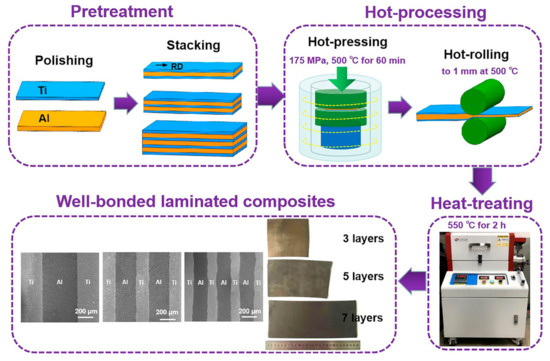
Figure 1.
The schematics to fabricate Ti/Al multilayered composites by hot-pressing and hot-rolling.
- The cleaned sheets were alternately stacked in the order of Ti, Al along the same direction and the outermost layer is Ti, LMCs with totals of three, five, and seven layers (Ti/Al/Ti, Ti/Al/Ti/Al/Ti, and Ti/Al/Ti/Al/Ti/Al/Ti) were set up, followed by putting them into the hot-pressing die.
- Hot-pressing was performed under 175 MPa and 500 °C for 60 min.
- The hot-pressed LMCs were rolled at 500 °C and a speed of 20 rpm; finally, the LMCs were thinned to 1 mm.
- The hot-rolled LMCs is vacuum annealed at 550 °C for 2 h and then air-cooled.
2.2. Microstructure
Metallographic specimens are fabricated by standard mechanical grinding and polishing, and the observation surfaces are the rolling-direction-normal-direction (RD-ND) planes. The microstructure and interfacial morphology of LMCs are observed by Scanning Electron Microscope (SEM) (SU8010, Hitachi Group, Tokyo, Japan). The texture evolution of Ti layer in RD-ND planes is analyzed by Oxford electron backscatter diffraction (EBSD) (OIM™, EDAX lnc., Mahwah, NJ, USA), and Channel 5 software (Oxford Instruments, Abingdon, UK) is used to process data.
2.3. Deep Drawing
The rounded blanks of LMCs with the diameters of 80 mm, 85 mm, 90 mm, 95 mm, 100 mm, and 105 mm were prepared, and the edges of the blanks were polished with sandpaper to avoid stress concentration. Then, ultrasonic cleaning and rapid drying were performed. The drawing speed of 3 mm/min was adopted to deep drawing at room temperature to obtain the LDR of the LMCs. The formula to calculate LDR is given as follows:
where Dm is the maximum initial diameter of the blank that can be successfully drawn, d is the diameter of the punch and is 38 mm in the study. The definition of Dm is as follows. The diameter of the blank is (D − 5) in the (i − 1)th experiment, and the forming limit of LMCs has not been reached if the blank is successfully deep drawn. Then the blank with a diameter of D is successfully deep drawn in the i-th experiment. However, the blank with a diameter of (D + 5) is broken in the (i + 1)th experiment, which indicates that the blank with a diameter of D is the largest initial diameter that can be successfully drawn (Dm = D).
LDR = Dm/d,
3. Results and Discussion
3.1. Microstructure
The inverse pole figures (IPF) and the pole figures (PF) of Ti layer in LMCs with different layers along the RD-ND plane are shown in Figure 2. It can be seen that both Ti and Al experience static recrystallization (SRX) to different degrees. All LMCs show alternating laminated features of fine-grained Ti and coarse-grained Al. The abnormally coarse Al grains are attributed to the recrystallization and grain growth during annealing. The grain size of Ti reduces and the grain-size gap between Ti and Al increases with the increase of layers. The bimodal structure is likely to improve the mechanical properties and formability of LMCs [14]. Ti has an HCP crystal structure, and its slip systems are limited at room temperature. Moreover, Ti has a relatively higher strength compared with Al. Therefore, the microstructure evolution of Ti, besides the Ti/Al interface, has a greater impact on the mechanical properties of LMCs. It is found from the PF that Ti layers exhibit basal texture <0001>//ND, and the texture strengths of Ti layers in LMCs with three, five, and seven layers are 11.69, 7.85, and 5.63, respectively. The texture strength of Ti gradually weakens with the increase of layers, and the c-axis of Ti grains gradually deflects from ND to TD. LMCs with more layers experience more severe deformation and gain higher storage energy, which promotes recrystallization and grain rotation during annealing, which leads to orientation softening of Ti, thereby weakening their basal textures [15]. It shows that although the multilayered structure cannot eliminate the preferred orientation of Ti grains, the inclination of the c-axis and the weak basal texture are beneficial to the basal slip with the increase of layers during plastic deformation, which helps to improve the mechanical properties of LMCs, such as enhancing elongation and reducing yield strength [16].
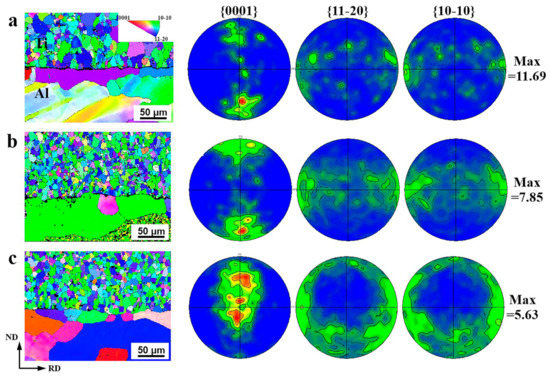
Figure 2.
The inverse pole figures (IPF) and the pole figures (PF) of Ti layers in Ti/Al multilayered composites with (a) three layers, (b) five layers, and (c) seven layers along the RD-ND plane.
3.2. Formability Indexes
The true stress-strain (σ–ε) curves of LMCs with different layers along the RD, 45°, and TD are shown in Figure 3a–c, respectively. The formability of LMCs is strongly affected by σs/σb (where σs and σb represents the yield strength and the ultimate tensile strength, respectively, and σs/σb represents the yield ratio), n values, and r values. The σs/σb, n values, and r values of LMCs are obtained through uniaxial tensile tests, and the results are summarized in Table 1. The σs/σb of all LMCs is the largest in TD, followed by 45° direction, and the smallest in RD. The average σs/σb of three-, five-, and seven-layer LMCs is 0.7682, 0.6993, and 0.6888, respectively. The σs/σb gradually decreases with the increase of layers. A small σs/σb indicates that LMCs have a longer uniform plastic deformation stage and can withstand more permanent deformation, which can effectively improve the formability. Feyissa et al. [17] also confirmed that a small σs/σb could prevent local deformation or premature necking of LMCs, thereby facilitating the stamping of LMCs. The relatively weak texture of LMCs with more layers leads to the decrease of the yield strength (YS) of the LMCs; that is, a relatively small σs/σb, which is conducive to dispersing local strains of LMCs and obtaining excellent formability [18].
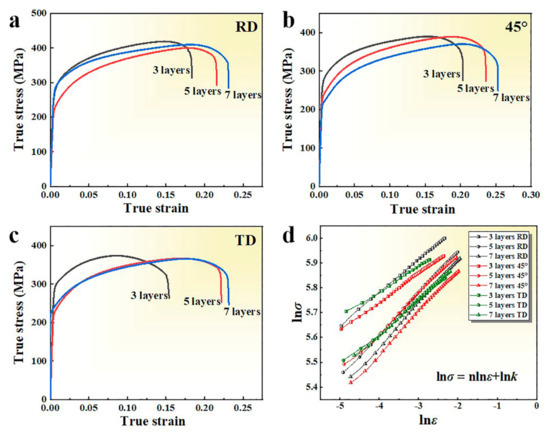
Figure 3.
The true stress-strain curves of Ti/Al multilayered composites with different layers along (a) RD, (b) 45°, (c) and TD; and (d) the lnε-lnσ curves of tension true stress-strain of Ti/Al multilayered composites.

Table 1.
The yield ratio, n and r values of LMCs with different layers along RD, 45°, and TD.
The n values of LMCs are determined by calculating the slope of the lnε–lnσ curve from the uniform plastic deformation stage of the tensile true stress-strain curve, as shown in Figure 3d. The n values of LMCs are basically the largest in RD, followed by the 45° direction, and the smallest in TD. The average n values of three-, five- and seven-layer LMCs are 0.1162, 0.1563, and 0.1653, respectively. The n values gradually decrease with the increase of layers, which means that LMCs have a greater range of elongation before necking [19]. The basal texture distribution in LMCs with more layers is relatively weak, and a higher n value will reduce plastic instability, thereby enhancing the formability [20,21]. Huang et al. [15] also confirmed that weak basal texture leads to a large n value. The orientation softening effect is introduced due to the weak basal texture, thereby maintaining more permanent deformation and resulting in greater ultimate formability. Kang et al. [22] and Somekawa et al. [23] also showed that Mg with weak basal texture has a higher n value, because a large number of grains would select preferred orientation. Wang et al. [24] reported that materials with a large n value could withstand great strain hardening and maintain severe deformation. Also, previous researches have confirmed that the low yield strength and high uniform elongation of LMCs are usually associated with high n values [25], which is consistent with the conclusion shown in Figure 3.
A true strain of 7% is used to determine the r values of LMCs. The average r values of three-, five- and seven-layer LMCs are 1.79, 1.64, and 1.53, respectively. The r values gradually decrease with the increase of layers. A low r value indicates that the sheet is easy to deform in the thickness direction, which is beneficial to improve the formability at room temperature [26]. Two main reasons should be considered for the decrease of the r value. First, the stress-strain transfer via more interface makes the LMCs deformation more uniform with the increase of layers, and LMCs are prone to uniform plastic deformation, resulting in a decrease of the r value. Secondly, the r values largely depend on the texture. Compared with other LMCs, the Ti layer in LMCs with three layers has a stronger basal texture; therefore, their basal and non-basal slip systems have relatively higher critical shear stresses, which require higher energy to start. It is difficult for LMCs with three layers to coordinate the strain in the thickness direction, resulting in a larger r value [24]. However, the recrystallization degree of Ti increases with the increase of layers, and new recrystallized grains are formed, which weakens the rolling texture and facilitates the softening of the Ti grain orientation, thereby reducing the r values.
3.3. Deep Drawability
3.3.1. Limit-Drawing Ratio
The cylindrical parts of LMCs with three layers, five layers, seven layers with various diameters and their LDRs are shown in Figure 4a–d, respectively. For three-layer LMCs, cylindrical parts are successfully drawn for the blanks with a diameter of 95 mm or less, while a blank with a diameter of 100 mm is ruptured when drawn to a displacement of 25.18 mm. Therefore, a cylindrical part with a maximum blank diameter of 95 mm can be successfully drawn, and the LDR of three-layer LMCs is 2.375. For five-layer and seven-layer LMCs, cylindrical parts are successfully drawn for the blank with a diameter of 85 mm, 90 mm, 95 mm, and 100 mm, while the blank with a diameter of 105 mm is ruptured at the corner of the punch near the wall. Therefore, the LDR of both five-layer and seven-layer LMCs is 2.50. The above results show that the deep drawability of LMCs can be improved by the multilayered structure configuration. In addition, it is observed that the cylindrical parts are broken at the corner of the punch near the cylindrical wall and gradually expand toward the flange. The largest openings of the LMCs are facing RD, and the height of the opening gradually decreases symmetrically to both sides, which indicates that the crack originates from RD.
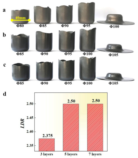
Figure 4.
The deep-drawing parts of Ti/Al multilayered composites with (a) three layers, (b) five layers, (c) seven layers with various diameters; and (d) limit-drawing ratio (LDR) of Ti/Al multilayered composites. (where Φ 40 mm marked in deep-drawing parts refers to the punch diameter, and Φ 80 mm—Φ 105 mm refers to the blank diameter before deep-drawing).
3.3.2. Deep-Drawing Force
The punch-force-displacement curves of the cylindrical parts with different initial diameters of LMCs are shown in Figure 5. The punch force gradually increases with the increase of the diameter of LMCs, which is attributed to the yield limit of the outermost materials of the LMCs becoming higher with the increase of the diameter of the punch [19]. As the hardening of the LMCs becomes more and more obvious, a significant increase in the drawing force results. At this time, the thinning of LMCs will also increase with the increase of the diameter, which increases the possibility of rupture in the corner of the LMCs. LMCs show almost the same changing trend of drawing force with the increase of punch displacement, and each LMC displays obvious second drawing force fluctuations besides the peak force. It can be obtained that the peak drawing forces of three-, five- and seven-layer LMCs are 53.43 kN, 62.15 kN, and 66.28 kN, respectively, which indicates that the multilayered structure configuration of LMCs can increase the ultimate drawing strength (the peak drawing forces of LMCs with the largest diameter that can be successfully drawn).
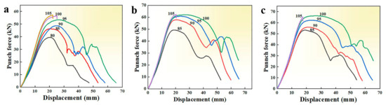
Figure 5.
Punch-force-displacement curves of Ti/Al multilayered composites with (a) three layers, (b) five layers, and (c) seven layers.
3.3.3. Wall Thickness
The wall-thickness reduction rate S is adopted to evaluate the change of the wall thickness of the cylindrical parts, and the mathematical expression is as follows.
S = (tc − t0)/t0
The wall-thickness reduction rate of the outer Ti layer, Al layer, and the total LMCs along the RD-ND plane of the cylindrical parts with three-, five-, and seven-layer LMCs from the center of the cylindrical part at an interval of 0.5 mm are shown in Figure 6. The variation of wall thickness of cylindrical parts can be roughly divided into three areas: the bottom with hardly any deformation; the corner and the lower area of the wall with a large extent of thinning; and the thickened wall. The total thinning rates of the outer Ti, Al layer, and LMCs as a whole have similar change rules. The sheets experience minimal deformation at the bottom of the cylindrical part of 0 mm–12 mm, which is caused by the biaxial tension stress in this area. The sheets are thinned due to bending deformation at the corner of the punch of 12 mm to approximately 20 mm. Also, the thinning of the sheets occurs at the lower cylinder wall of 20 mm to approximately 40 mm. Cracks easily occur at the corner of the punch near the cylinder wall, as reported in the previous studies [27,28]. In the study, the thickness reduction of the sheets is the most serious at a distance of 20 mm (where the wall is tangent to the corner), which is a danger area during deep drawing. The circumferential stress of the sheets in the area disappears, and only uniaxial tensile stress is applied, which may cause the necking and rupture of the sheets [29]. While the sheets thicken, mainly due to the circumferential shrinkage at the wall of greater than 40 mm. The sheets are thickening more seriously at the flange area closer to the outside during the deep drawing. The materials accumulate at the mouth of the deep-drawing part, and the cylinder wall thickens obviously when the flange part is completely transformed into the cylinder wall.
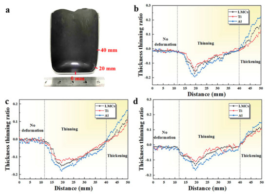
Figure 6.
The thickness-thinning ratio of (a) the deep-drawing parts of Ti/Al multilayered composites with (b) three layers, (c) five layers, and (d) seven layers along the RD-ND surface.
The thickness-thinning ratio of the deep-drawing parts at the corner and the thickening ratio of the deep-drawing parts at the wall of 50 mm from the bottom center are summarized in Table 2 and Table 3, respectively. The results show that the thinning rate of Al at the corner and the thickening rate at the wall are always greater than Ti, because the deformation resistance of Al is lower than that of Ti [30]. It can be seen that the thickness–thinning ratio of the deep-drawing parts at the corner and the thickening ratio of the deep-drawing parts at the wall of 50 mm from the bottom center of the outer Ti layer, the Al layer, and the LMC as a whole gradually decreases with the increase of layers. The interfaces increase with the increase of layers, which is beneficial for transfer deformation, for dispersing and releasing stored energy, and for promoting coordinated deformation of component metals. Thus, the load distribution of LMCs with more layers is more uniform, which is beneficial for increasing the forming limits of LMCs. Huang et al. [16] confirmed that the stress-strain transfer via the interface could coordinate the deformation of component metals. Fan et al. [11] also found Ti/Al composites with more interfaces (or thin component metal layers) exhibited better-coordinated deformation capacity, and possessed sufficient ductility, excellent bending deformation property, and a high forming limit, which is consistent with the results of this work.
Table 2.
The thickness-thinning ratio of the deep-drawing parts of LMCs with different layers at the corner section.
Table 3.
The thickening ratio of the deep-drawing parts of LMCs with different layers at the wall section of 50 mm from the bottom center.
3.3.4. The Forming Behavior at Each Stage of Deep Drawing
Three-layer LMCs with a diameter of 95 mm were drawn to different heights; their deep-drawing parts and punch-force-displacement curve marked with the A1–A5 stages are shown in Figure 7. The drawing punch force rises rapidly at the A1 stage, and the peak drawing force is reached at about 53.43 kN at the A2 stage. In addition to overcoming the deformation resistance of the cylindrical wall, the punch force needs to overcome the frictional resistance between the surface of the blank and the die, the frictional resistance when the blank slides over the corners of the cavity die, and the bending resistance formed by the bending of the blank at the corner of the cavity die. At the A1 and A2 stages, the materials in the flange area of the blank bear more and more severe tangential compressive stress as the drawing processes, which causes an increase of the thickness in the flange area, thus the frictional resistance between the surface of the blank and the die increase sharply. The corners of the punch have been completely formed at the A2 stage, and the surface quality is excellent without wrinkling, as shown in Figure 7. Some researchers have found that the peak drawing force could be reached when the flange diameter of the drawing part is 0.7 to approximately 0.9 times of the original diameter of the blank. For example, Tang et al. [28] found that Mg/Al composites bear the peak drawing force when the flange diameter is about 0.875 of the initial diameter of the blank. Lange, K. et al. [31] also reported that the peak punch force of a single-layer sheet is generated when the outer diameter of the drawing part is about 0.77 of the initial blank diameter. In the study, the flange diameter of the cylindrical part is about Φ = 75 mm at the peak drawing force, and the initial diameter of LMCs is Φ = 95 mm. Therefore, it can be concluded that the drawing force reaches maximum when the flange diameter is about 0.79 of the initial diameter of the LMCs. This is consistent with the results of previous studies.
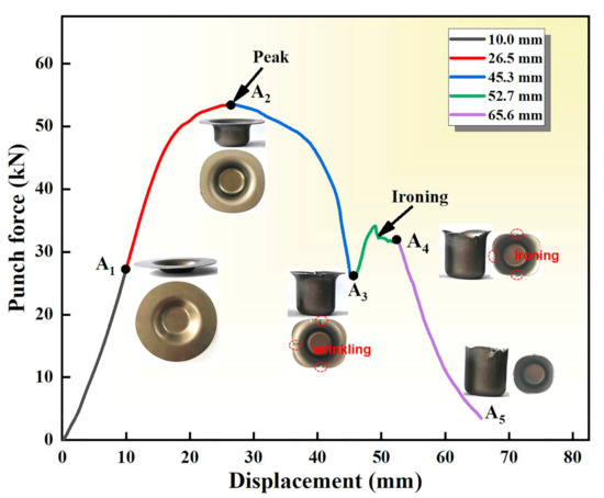
Figure 7.
The deep-drawing parts and punch-force-displacement curve of three-layers with the diameter of 95 mm recording the drawing stages of A1–A5. The punch force is gradually increased and then stabilized at the A4 stage. The wrinkles generated in the flange edge are gradually pulled into the fixed and narrow gap between punch and cavity die, and the material flow is restricted by the gap size, which leads to serious positive pressure stress in the upper cylinder wall. Then the friction between the blank and the die increases sharply, thus the punch force required to overcome the frictional resistance increases, and the second peak is formed in the punch-force-distance curves.
The drawing force reduces significantly at the A3 stage. The contact area of the flange with the blank holder and the upper surface of cavity die is shrinking, thus the friction is reduced. Obvious wrinkles can be observed at the edge of the A3 part. The materials in the flange area bear tangential compressive stress at the A3 stage, which causes an increase of the thickness in the flange area. In particular, the materials at the outermost edge of the flange experience the largest tangential compressive stress, resulting in the most dramatic thickening. The materials of flange area in the corner of the cavity die will wrinkle due to plastic instability when the tangential compressive stress exceeds the limit of blank holder force. The blank is fully drawn at the A5 stage. The drawing force is gradually reduced at the A5 stage, and the cylindrical part completely leaves the corner of the cavity die. It can be observed from the morphology of the A5 part that the mouth of the cylindrical part is not flat. On the one hand, it may be attributed to some deviations caused by manual alignment before the deep-drawing test. On the other hand, the anisotropy of the LMCs leads to the earrings at the mouth of the deep-drawing parts. The earring parameter(∆r) of the LMCs is less than 0, as shown in Table 1, so the earring is easily generated at a 45° direction with RD.
3.4. Interface Evolution of Cylindrical Parts
SEM images of the deep-drawing parts of LMCs with different layers along the RD-ND surface at the bottom, corner, and wall are shown in Figure 8a–c, respectively. It can be seen from Figure 8a that the Ti/Al interfacial morphologies at the bottom of the deep-drawing parts show more and more intense wavy structure with the increase of layers. The Ti/Al interface is relatively straight in three-layer LMCs. The large-scale curved interface morphology is displayed in five-layer LMCs. While the Ti/Al interface exhibits a large number of uniform wavy morphologies with small amplitude in seven-layer LMCs. It can be seen from the interfacial morphologies at the corner of the deep-drawing parts shown in Figure 8b that the Ti/Al interface in three-layer LMCs is still straight, and a small, wave-like, interlocking interfacial structure appears in five-layer LMCs. The Ti/Al interface in seven-layer LMCs has a dense, zigzagging interfacial structure. The materials at the corner of the deep-drawing parts experience severe deformation due to bending and friction, especially the extrusion deformation in the thickness direction, which directly leads to the change of the interfacial morphology. The component metals in LMCs become thinner with the increase of layers, and the increased interfacial pressure promotes the formation of an increasingly firm overlapped interfacial structure to coordinate deformation. The Ti/Al interfaces in all LMCs display the embedded structure due to the compressive stress in thickness direction and tangential extrusion, as shown in the thickened area of the wall of the deep-drawing parts in Figure 8c. The Ti/Al interface in three-layer LMCs displays rectangular-like embedded morphology. Plenty of arc-shaped embedded interface with varying sizes can be observed in five-layer LMCs, and the interfacial bonding is relatively soft. The interface in seven-layer LMCs exhibits relatively sharp tooth-like embedded structures with large protrusions and depressions. During the deep drawing, the changes of interfacial morphology increase the actual contacted area between the Ti and Al layers with the increase of layers, which is beneficial to enhance the interfacial bonding strength. The internal stress is released at the interface due to the load transfer across the interface, therefore the energy of LMCs is reduced, and LMCs can deform more stably. The strain distribution between the Ti and Al layers is more uniform due to the strain transfer across the interface, and local strain hardening is alleviated. The above effects are beneficial to the coordinated deformation between the Ti and Al layers and improve the formability of LMCs. Therefore, LMCs with more layers show deeper drawability.
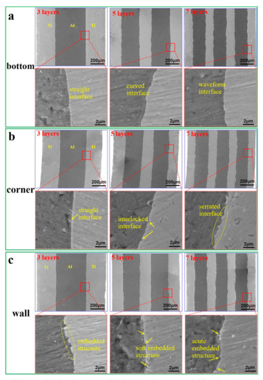
Figure 8.
SEM images of the deep-drawing parts of Ti/Al multilayered composites with different layers along the RD-ND surface at the (a) bottom, (b) corner, and (c) wall.
3.5. Fracture of Cylindrical Parts of Ti/Al Multilayered Composites
SEM images of the deep-drawing broken parts of LMCs with different layers at the cracks are shown in Figure 9. Necking occurs in both Ti and Al layers, and the angle between the shear fracture direction of the Ti layer and the displacement direction of the punch is about 45°. While the deformation of the Al layer is restricted by the hard Ti layer and the interface phase layer, resulting in tearing at the cracks. For three-layer LMCs, the soft Al layer in the middle ruptures when the drawing load exceeds its ultimate strength. Delamination and tearing are generated in Ti/Al interfaces due to the weak interfacial bonding with the increase of the drawing force. Then, crack deflection occurs at the interfacial delamination when the cracks that initiated in the Al layer propagate to the interface. Finally, the inner and outer Ti layers are fractured, and the LMCs fail to conduct deep drawing. The serious interfacial delamination doesn’t appear during the deep drawing for five-layer LMCs due to the improved interfacial bonding, and only some local debonding points and microcracks appear. The crack propagation becomes more tortuous due to the increase of the interfaces. Large deflection and tearing are produced due to the complex stress state at the interface when the crack propagates to the interface. Ultimately the formability of LMCs is improved because of the effects that the interfaces absorb energy and hinder the crack propagation. The Ti/Al interface in seven-layer LMCs produces local debonding points and slight delamination. Seven-layer LMCs have more interfaces, and the load transfer via the interface makes the stress distribution more uniform [16]. The thin layer spacing also helps coordinate deformation between component metals [11]. Therefore, the increase of the interfaces is conducive to the improvement of the deep-drawing limit of LMCs.
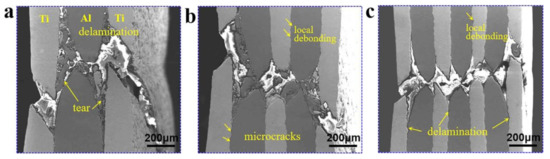
Figure 9.
SEM images of the deep-drawing broken parts of Ti/Al multilayered composites with (a) three layers, (b) five layers, and (c) seven layers along the RD-ND surface at the cracks.
4. Conclusions
The deep drawability of LMCs was evaluated via deep drawing at room temperature. The effects of interface on the deep drawability of LMCs were studied, and the microstructure evolution of the component metals and interfaces of the cylindrical parts was explored. The following conclusions can be drawn:
- The texture strength of the Ti gradually weakens with the increase of layers, which leads to the smaller σs/σb, r values, and the larger n values, thus the deep drawability of LMCs enhances effectively.
- LMCs with more layers have a higher LDR and can withstand a higher ultimate drawing force.
- The Ti/Al interfaces in three-, five- and seven-layers LMCs exhibit straight, small-wave-like interlocking, and dense serrated structures at the corner of the cylindrical parts, respectively. The component metals in LMCs become thinner with the increase of layers, and the increased interfacial pressure promotes the formation of an increasingly firm overlapped interfacial structure to coordinate deformation.
- The number of interfaces increase with the increase of layers, and the load transfer effect via the interfaces make the stress distribution between layers more uniform, which helps coordinate deformation. Deflection and tearing occur when the cracks propagate to the interface owing to the complex stress state, which hinders and delays the crack penetration, thereby improving the deep drawability of LMCs.
Author Contributions
Conceptualization, M.C. and K.-K.D.; methodology, M.C. and C.-J.W.; software, K.-B.N.; validation, M.C., C.-J.W., K.-K.D. and K.-B.N.; formal analysis, M.C.; investigation, M.C. and K.-K.D.; resources, C.-J.W.; data curation, K.-K.D.; writing—original draft preparation, M.C.; writing—review and editing, M.C.; visualization, C.-J.W. and K.-B.N.; supervision, K.-K.D.; project administration, K.-K.D.; funding acquisition, K.-K.D. All authors have read and agreed to the published version of the manuscript.
Funding
This work was supported by “National Natural Science Foundation of China” (Grants. 51771128 and 51771129), Shanxi province science and technology major projects (Grant no.20181101008), the Program for the Outstanding Innovative Teams of Higher Learning Institutions of Shanxi, and the special fund project for guiding local science and technology development by the central government (YDZX20191400002734).
Data Availability Statement
Not applicable.
Conflicts of Interest
The authors declare no conflict of interest.
References
- Song, H.; Hao, W.; Mu, X.; Han, T.; Che, C.; Geng, G. Effect of Pulse Current-Assisted Rolling on the Interface Bonding Strength and Microstructure of Cu/Al Laminated Composite. Metals 2020, 10, 1555. [Google Scholar] [CrossRef]
- Yan, Z.; Xu, G.; Suo, J. Effect of Transition Layer on Properties of Tungsten-Tantalum (W-Ta) Laminated Composite. Metals 2020, 10, 558. [Google Scholar] [CrossRef]
- Du, Y.; Fan, G.-H.; Yu, T.; Hansen, N. Laminated Ti-Al Composites: Processing, Structure and Strength. Mater. Sci. Eng. A 2016, 673, 572–580. [Google Scholar] [CrossRef]
- Hwu, K.L.; Derby, B. Fracture of Metal-Ceramic Laminates-I. Transition from Single to Multiple Cracking. Acta Metall. 1999, 47, 529–543. [Google Scholar] [CrossRef]
- Inoue, J.; Nambu, S.; Ishimoto, Y.; Koseki, T. Fracture Elongation of Brittle/Ductile Multilayered Steel Composites with a Strong Interface. Scr. Mater. 2008, 59, 1055–1058. [Google Scholar] [CrossRef]
- Zhang, X.C. Preparation, Microstructure and Properties of Particle Reinforced Magnesium Sheet. Master’s Thesis, Taiyuan University of Technology, Taiyuan, China, 2020. [Google Scholar]
- Nie, H.H. The Microstructures and Thermal Deformation Behavior of Al/Mg/Al Clad Sheets. Ph.D. Thesis, Taiyuan University of Technology, Taiyuan, China, 2017. [Google Scholar]
- Gao, K.; Zhang, X.; Liu, B.; He, J.; Feng, J.; Ji, P.; Fang, W.; Yin, F. The Deformation Characteristics, Fracture Behavior and Strengthening-Toughening Mechanisms of Laminated Metal Composites: A Review. Metals 2019, 10, 4. [Google Scholar] [CrossRef]
- Li, X.-B.; Yang, Y.; Xu, Y.-S.; Zu, G.-Y. Deformation Behavior and Crack Propagation on Interface of Al/Cu Laminated Composites in Uniaxial Tensile Test. Rare Met. 2020, 39, 296–303. [Google Scholar] [CrossRef]
- Nie, H.; Chi, C.; Chen, H.; Li, X.; Liang, W. Microstructure Evolution of Al/Mg/Al Laminates in Deep Drawing Process. J. Mater. Res. Technol. 2019, 8, 5325–5335. [Google Scholar] [CrossRef]
- Fan, M.; Domblesky, J.; Jin, K.; Qin, L.; Cui, S.; Guo, X.; Kim, N.; Tao, J. Effect of Original Layer Thicknesses on the Interface Bonding and Mechanical Properties of Ti Al Laminate Composites. Mater. Des. 2016, 99, 535–542. [Google Scholar] [CrossRef]
- Qin, L.; Wang, H.; Cui, S.; Wu, Q.; Fan, M.; Yang, Z.; Tao, J. Characterization and Formability of Titanium/Aluminum Laminate Composites Fabricated by Hot Pressing. J. Mater. Eng. Perform. 2017, 26, 3579–3587. [Google Scholar] [CrossRef]
- Kaya, İ.; Cora, Ö.N.; Acar, D.; Koç, M. On the Formability of Ultrasonic Additive Manufactured Al-Ti Laminated Composites. Metall. Mater. Trans. A 2018, 49, 5051–5064. [Google Scholar] [CrossRef]
- Yu, H.; Lu, C.; Tieu, A.K.; Li, H.; Godbole, A.; Kong, C. Annealing Effect on Microstructure and Mechanical Properties of Al/Ti/Al Laminate Sheets. Mater. Sci. Eng. A 2016, 660, 195–204. [Google Scholar] [CrossRef]
- Huang, X.; Suzuki, K.; Saito, N. Textures and Stretch Formability of Mg-6Al-1Zn Magnesium Alloy Sheets Rolled at High Temperatures up to 793 K. Scr. Mater. 2009, 60, 651–654. [Google Scholar] [CrossRef]
- Huang, M.; Xu, C.; Fan, G.; Maawad, E.; Gan, W.; Geng, L.; Lin, F.; Tang, G.; Wu, H.; Du, Y.; et al. Role of Layered Structure in Ductility Improvement of Layered Ti-Al Metal Composite. Acta Mater. 2018, 153, 235–249. [Google Scholar] [CrossRef]
- Feyissa, F.; Ravi Kumar, D.; Rao, P.N. Characterization of Microstructure, Mechanical Properties and Formability of Cryorolled AA5083 Alloy Sheets. J. Mater. Eng. Perform. 2018, 27, 1614–1627. [Google Scholar] [CrossRef]
- Pan, F.; Wang, Q.; Jiang, B.; He, J.; Chai, Y.; Xu, J. An Effective Approach Called the Composite Extrusion to Improve the Mechanical Properties of AZ31 Magnesium Alloy Sheets. Mater. Sci. Eng. A 2016, 655, 339–345. [Google Scholar] [CrossRef]
- Kotkunde, N.; Deole, A.D.; Gupta, A.K.; Singh, S.K.; Aditya, B. Failure and Formability Studies in Warm Deep Drawing of Ti-6Al-4V Alloy. Mater. Des. 2014, 60, 540–547. [Google Scholar] [CrossRef]
- Del Valle, J.A.; Carreño, F.; Ruano, O.A. Influence of Texture and Grain Size on Work Hardening and Ductility in Magnesium-Based Alloys Processed by ECAP and Rolling. Acta Mater. 2006, 54, 4247–4259. [Google Scholar] [CrossRef]
- Karaman, I.; Sehitoglu, H.; Beaudoin, A.J.; Chumlyakov, Y.I.; Maier, H.J.; Tomé, C.N. Modeling the Deformation Behavior of Hadfield Steel Single and Polycrystals Due to Twinning and Slip. Acta Mater. 2000, 48, 2031–2047. [Google Scholar] [CrossRef]
- Kang, D.H.; Kim, D.-W.; Kim, S.; Bae, G.T.; Kim, K.H.; Kim, N.J. Relationship Between Stretch Formability and Work-Hardening Capacity of Twin-Roll Cast Mg Alloys at Room Temperature. Scr. Mater. 2009, 61, 768–771. [Google Scholar] [CrossRef]
- Somekawa, H.; Mukai, T. Fracture Toughness in Mg-Al-Zn Alloy Processed by Equal-Channel-Angular Extrusion. Scr. Mater. 2006, 54, 633–638. [Google Scholar] [CrossRef]
- Wang, L.; Zhang, Z.; Cao, M.; Zhang, H.; Han, T.; Yang, Q.; Wang, H.; Cheng, W. Effect of Pre-Strain Levels and High Temperature Annealing on the Formability of AZ31 Mg Alloy Thin Sheet During Stretch Deformation. Mater. Res. Express 2019, 6, 10. [Google Scholar] [CrossRef]
- Wang, L.; Cao, M.; Cheng, W.; Zhang, H.; Cao, X.; Mostaed, E. Improved Stretch Formability of AZ31 Magnesium Thin Sheet by Induced {10–12} Tension Twins. JOM 2018, 70, 2321–2326. [Google Scholar] [CrossRef]
- Zhang, H.; Huang, G.; Kong, D.; Sang, G.; Song, B. Influence of Initial Texture on Formability of AZ31B Magnesium Alloy Sheets at Different Temperatures. J. Mater. Process. Technol. 2011, 211, 1575–1580. [Google Scholar] [CrossRef]
- Bagherzadeh, S.; Mirnia, M.J.; Mollaei Dariani, B. Numerical and Experimental Investigations of Hydro-mechanical Deep Drawing Process of Laminated Aluminum/Steel Sheets. J. Manuf. Process. 2015, 18, 131–140. [Google Scholar] [CrossRef]
- Wei, T.; Xiao-Qing, C.; Zhi-Qing, C.; Wen-Wu, Y. Deep Drawability Study and Process Optimization on 5052/AZ31/5052 Laminated Sheets. Light Alloy. Fabr. Technol. 2018, 46, 54–58. [Google Scholar]
- Atrian, A.; Fereshteh-Saniee, F. Deep Drawing Process of Steel/Brass Laminated Sheets. Compos. Part. B-Eng. 2013, 47, 75–81. [Google Scholar] [CrossRef]
- Ma, M.; Meng, X.; Liu, W.C. Microstructure and Mechanical Properties of Ti/Al/Ti Laminated Composites Prepared by Hot Rolling. J. Mater. Eng. Perform. 2017, 26, 3569–3578. [Google Scholar] [CrossRef]
- Lunge, K. Handbook of Metalforming; Society of Manufacturing Engineers: Dearborn, MI, USA, 1985; pp. 688–693. [Google Scholar]
Publisher’s Note: MDPI stays neutral with regard to jurisdictional claims in published maps and institutional affiliations. |
© 2021 by the authors. Licensee MDPI, Basel, Switzerland. This article is an open access article distributed under the terms and conditions of the Creative Commons Attribution (CC BY) license (https://creativecommons.org/licenses/by/4.0/).