Article

Different Response of Cast and 3D-Printed Co-Cr-Mo Alloy to Heat Treatment: A Thorough Microstructure Characterization

1
FZU—Institute of Physics of the Czech Academy of Sciences, Na Slovance 1999/2, 182 00 Prague 8, Czech Republic
2
Department of Metals and Corrosion Engineering, University of Chemistry and Technology Prague, Technicka 5, 166 28 Prague 6, Czech Republic
3
NETME Centre, Faculty of Mechanical Engineering, Brno University of Technology, Technicka 2, 616 69 Brno, Czech Republic
*
Author to whom correspondence should be addressed.
Metals 2021, 11(5), 687; https://doi.org/10.3390/met11050687
Submission received: 1 April 2021 / Revised: 19 April 2021 / Accepted: 20 April 2021 / Published: 22 April 2021
(This article belongs to the Special Issue Processing and Treatment of Hexagonal Metallic Materials)

Abstract

:
The Co-Cr-Mo alloy is a biomaterial with very good corrosion resistance and wear resistance; thus, it is widely applied for knee replacements. The wear resistance is influenced by the amount of hcp phase and morphology of carbidic precipitates, which can both be altered by heat treatment. This study compares a conventional knee replacement manufactured by investment casting with a material prepared by the progressive technology of 3D printing. The first set of results shows a different response of both materials in increasing hardness with annealing at increasing temperatures up to the transformation temperature. Based on these results, solution treatment and subsequent aging at conditions to reach the maximum hardness was applied. Microstructural changes were studied thoroughly by means of optical, scanning electron and transmission electron microscopy. While increased hardness in the conventional material is caused by the precipitation of fine hard carbides combined with an increase in the hcp phase by isothermal transformation, a massive fcc → hcp transformation is the main cause for the hardness increase in the 3D-printed material.

1. Introduction

Ternary Co-Cr-Mo (CCM) alloys exhibit a combination of properties suitable for a wide range of applications. An important application sector is the fabrication of orthopedic implants for knee and hip replacements or dental implants thanks to their biocompatibility, corrosion resistance and high wear resistance. CCM alloys are also widely applied in the aviation industry thanks to high mechanical properties up to high temperatures [1,2]. On the other hand, high mechanical properties, especially high hardness, also represent a certain drawback of these alloys, in terms of poor formability and machinability. A desired part design is thus technologically demanding to be achieved. Conventionally, the CCM alloys are thus processed by casting technologies, mostly by investment casting to avoid further machining [3,4]. A new perspective is opened up with the development of additive manufacturing technologies, commonly called 3D printing.
Three-dimensional printing not only enables economically and energetically more efficient manufacturing of hardly processable metallic materials, but also brings many other advantages. From the viewpoint of medical applications, 3D printing (especially powder bed fusion technologies consolidating fine metallic powders) enables accommodation of implants to the physiological needs of a specific patient or preparation of porous structures mimicking bone structure, reducing the mismatch between the mechanical properties of the artificial implant material and bone, and providing space for bone tissue ingrowth. In the field of aviation industry, the advantages of 3D printing are used for the production of parts structurally designed to reduce the weight of the part while maintaining its high mechanical properties [5,6].
Considering all these benefits, there have already been multiple studies dealing with the CCM alloys prepared by 3D-printing techniques, mainly selective laser melting (SLM) and electron beam melting (EBM), two main techniques of powder bed fusion. Many focused on process optimization to achieve fully dense material (e.g., [7,8,9]). Others characterized the 3D-printed material in terms of microstructure and mechanical performance [10,11,12,13] or corrosion behavior [14,15]. Dong et al. [16] showed that SLM has a positive effect on significantly increasing the fatigue life of Co–Cr–Mo–W alloy compared to a conventionally cast one. Xin et al. [17] found out that SLM-fabricated CCM alloy shows better biocompatibility than the cast counterpart, thus being a suitable option for biomedical applications. Some authors studied the effect of heat treatment [14,18,19].
Compared to the revolutionary 3D-printing technology, which is still in its infancy, the investment casting of CCM alloys has a long history of successful use as surgical implants. However, a number of implants showed a failure during their use due to wear debris acting abrasively on contacting interfaces. A heat treatment providing a substantial improvement in tribological properties is thus desirable [20].
The main factors that affect the wear resistance of CoCrMo alloys are the carbon amount, the homogeneity of the carbides distribution and the presence of the hcp crystal structure [21]. Saldívar-García and López [22] verified that the wear loss is significantly reduced when both CCM sliding components show a fully hcp structure. Similarly, other works confirmed [23,24] that the formation of hexagonal ε phase caused the increase in wear resistance for Co-based alloy despite its inherent brittle behavior compared to the fcc phase. Hard carbides positively influence the wear if they show good coherency with the surrounding matrix, protecting it from delamination. On the other hand, if carbides are loosely bound in the matrix, they can be pulled out, cause abrasive damage and enhance the wear loss [21].
Cast CCM alloys exhibit a dendritic γ-fcc metastable matrix due to the sluggish nature of the γ-fcc → ε-hcp transformation. Carbides appear on grain boundaries and in the interdendritic regions. Moreover, an intermetallic σ phase can appear in the microstructure. The most detrimental feature of the cast microstructure is a lamellar phase formed by interlayered plates of carbides (M23C6 or M6C where M = Cr, Mo, Co) and a second phase, which some authors report to be γ or σ phase [4]. The γ-fcc → ε-hcp transformation can be promoted by isothermal aging below the transformation temperature, Tc. Coarse carbides and undesirable lamellar structures containing carbides can be then transformed by high-temperature annealing above Tc. A combination of solution annealing and isothermal aging below Tc is thus a suitable way to improve the wear behavior [23].
The response of such heat treatment might be, however, different for CCM alloys prepared by 3D-printing techniques, as they show a significantly different microstructure. Rapid cooling yields in very fine microstructures with no or a minimal amount of secondary phases and generates high residual stresses [25]. Toh et al. [26] expressed concerns in their review article that carbides in the form of nanoparticles could have a negative effect on the tribocorrosion behavior of this alloy, as they could be easily dislodged from the matrix, e.g., in the alloy manufactured by EBM, which showed fine carbide precipitates on the grain boundary between fcc grains making the interface incoherent and weak [27]. Li et al. [28] observed an anisotropy in wear properties of a CCM alloy prepared by SLM and showed a positive effect of isothermal annealing on lowering the wear rate. However, no work directly comparing a 3D-printed CCM alloy with a cast one could be found. In the present paper, our aim is thus to compare directly the response of a conventionally manufactured Co-28Cr-6Mo alloy with this alloy prepared by SLM, one of the 3D-printing techniques based on the successive melting of small volumes of a “powder bed” by a precisely focused laser beam [29].

2. Materials and Methods

The studied material is a Co-28Cr-6Mo alloy (defined by the ASTM F75 standard). The conventionally manufactured material used for knee replacements was obtained from a commercial manufacturer of orthopedic surgical implants. It concerned a femoral component of a knee replacement prepared by investment casting. The chemical composition of the cast material, measured by X-ray fluorescence (XRF) using an Axios FAST spectrometer (Malvern Panalytical, Malvern, UK)) and by combustion analysis (Bruker G4 Icarus HF (Bruker, Billerica, MA, USA)), is given in Table 1.
For 3D printing, the selective laser melting (SLM) technology was used. A gas atomized powder purchased from SLM Solutions (SLM Solutions, Lübeck, Germany) was processed in an SLM Solution 280 HL machine (SLM Solutions, Lübeck, Germany) equipped with one 400 W laser. The powder was deposited into the building chamber in 50 µm thin layers and selectively melted by a laser of 275 W in power and 800 mm s−1 in scanning speed. A stripe scanning strategy was applied, with a hatching distance of 0.12 mm and rotation of stripe direction by 45° each layer. The chemical composition of the 3D-printed material is given in Table 1 as well.
To study the difference in the response of the alloy prepared by two different approaches to elevated temperatures, both materials were exposed to several temperatures in the range of 400–1000 °C (a step of 100 °C). Cylindrical samples were machined from both materials. One sample of each material was then put into a muffle furnace RHF 15/3 (Carbolite Gero Ltd., Sheffield, UK) pre-heated to the selected temperature and annealed for 4 h. After annealing, samples were quenched in water. Changes in hardness compared to the initial state were studied after grinding a surface layer of 1 mm in thickness to avoid measurement bias by oxidation. Vicker’s hardness with 10 kg load was measured ten times on each sample using a Wilson VH3300 hardness tester (Buehler, Lake Bluff, IL, USA). The obtained results enabled us to construct hardness–temperature curves. For the temperature of maximum hardness increase achieved, a time course of hardness change was studied. Conditions to achieve the maximum hardness were determined and used for heat treatment consisting of solution annealing at 1200 °C/2 h and subsequent aging.
For the complex microstructure characterization of the studied material states, samples were prepared in a standard metallographic way. After etching in aqua regia, microstructure was observed on an optical metallography microscope (OM) (Carl Zeiss AG, Oberkochen, Germany) and a scanning electron microscope (SEM) JEOL JSM-6010PLUS/LA (JEOL Ltd., Tokyo, Japan) equipped with an energy dispersive spectrometry (EDS) detector (JEOL Ltd., Tokyo, Japan). For the transmission electron microscopy (TEM), TEM foils were prepared perpendicular to the SLM building direction by polishing using ionized Ar in Gatan PIPs (Gatan GmbH, München, Germany). A FEI Tecnai TF20 X-twin microscope (FEI, Hillsboro, OR, USA) equipped with a field emission gun operated at 200 kV and an energy dispersive spectrometer (EDAX, Manhwah, NJ, USA) was used. Selected area electron diffraction (SAED) was applied for the qualitative determination of individual phases. The chemical composition of the phases was determined by TEM-EDS analyses in the scanning transmission electron microscopy (STEM) regime using a high-angle annular dark-field (HAADF) imaging detector (Fischione Instruments Inc., Export, PA, USA). Overall phase composition was determined by X-ray diffraction (XRD) using a PANalytical X’Pert PRO diffractometer (Malvern Panalytical, Malvern, UK)) with a Co anode (Kα = 0.179 nm).

3. Results

The results section is built on the comparison between the microstructures of conventionally cast Co-Cr-Mo alloy and an additively manufactured one (prepared by the SLM technology) and their responses to heat treatment.

3.1. Initial Microstructure

Microstructure of the Co-Cr-Mo alloy prepared additively by SLM shows a hierarchical microstructure consisting of macroscopic features caused by gradual melting and solidification of small volumes of the input powder (melting tracks in the section parallel to the building plate or melt pools in the section perpendicular to the building plate), columnar grains elongated in the building direction layer by layer and cellular substructure within grains. All the microstructural features are indicated in Figure 1. Such microstructure is typical for many alloys prepared by SLM [30,31,32]. The morphology of columnar grains is related to the epitaxial growth of grains from the previously solidified layer. Cellular microstructures are then the result of high cooling rates (up to 108 °C/s) [25]. Although the microstructure of Co-Cr-Mo alloy prepared by SLM was described in multiple papers [9,11,33,34,35], there are differences in the description of microstructural features, especially phase composition and cellular segregation. These differences probably stem from the different analytical techniques applied or different parameters of the SLM process which may influence the microstructure formation. We thus thoroughly characterized the material studied in this work in our previous paper [36].
The cells can be observed in different shapes on the cross-section (Figure 1d) due to their different orientation in each grain. In general, the cells obtain the shape of tubes of about 500 nm in diameter. The intercellular network is enriched in Mo as detected by SEM-EDS (Figure 2). According to TEM observations (Figure 3a), the cell walls are dislocation walls at which Mo atoms can segregate. Locally, nanoprecipitates of σ-phase (about 60 nm in diameter) were found in the cellular network. As revealed by TEM-EDS (Table 2), this phase is significantly enriched in Mo.
In terms of phase composition, most of the material is retained in the high-temperature γ-fcc phase. Only a certain fraction of ε-hcp can be formed by athermal martensite transformation during rapid cooling, which can be further increased by isothermal annealing inherent to the layer-wise SLM process [37]. We detected 28 vol% of hcp phase by XRD. As visible in the TEM micrograph in Figure 3b, hcp phase forms lamellae in the fcc matrix. The diffraction pattern showing the presence of both phases (Figure 3d) revealed the orientation relationship between fcc and hcp: {111}fcc ǁ {001}hcp; <110>fcc ǁ <100>hcp. The fringe contrast revealing stacking faults (SFs) in Figure 3c depicts that the nucleation of hcp occurs at SFs.
Compared to the additive manufacturing, the cast microstructure is the result of a relatively low cooling rate (tens of °C/min from the casting temperature of ~1550 °C to the room temperature). It is thus formed by coarse equiaxed grains with dendritic morphology (Figure 4a). Even so, the equilibrium phase composition is not reached due to the sluggish nature of the γ-fcc → ε-hcp transformation, which suppresses the athermal martensitic transformation. The γ-fcc phase thus remains in the microstructure at room temperature in the dominant fraction [20]. To increase the wear resistance of the material commonly used for knee implants, isothermal annealing below the transformation temperature (~970 °C [20]) is usually applied after casting to increase the ε fraction [23]. The material purchased for this study was annealed at 700 °C to achieve the ε fraction of 28%. The initial phase composition of the Co matrix is thus comparable to the initial 3D-printed microstructure. As visible in Figure 4a, the nucleation of hcp needles occurs predominantly from the center of the dendrite arms (darker areas), while the areas in the vicinity of interdendritic carbides remain fcc (lighter areas) due to the depletion in Cr and Mo by interdendritic microsegregation. These elements increase the stacking fault energy, so that their depletion hinders the γ-fcc → ε-hcp transformation [20]. The TEM image in Figure 5a shows the Co-fcc matrix with SFs which serve as nucleation sites for the ε-hcp needles. Diffraction pattern (Figure 5b) thus reveals both fcc and hcp phases (stripe patterns between diffraction points for the fcc matrix).
The XRD analysis determined the presence of two types of carbides: M23C6 (5.0%) and M6C (1.3%). However, as visible from the micrographs (Figure 4b–d), carbides occur in three different morphologies:
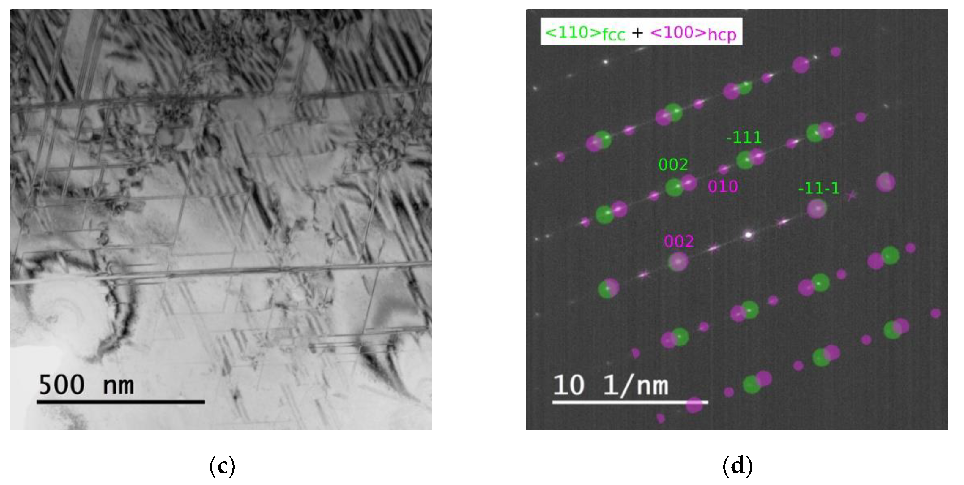
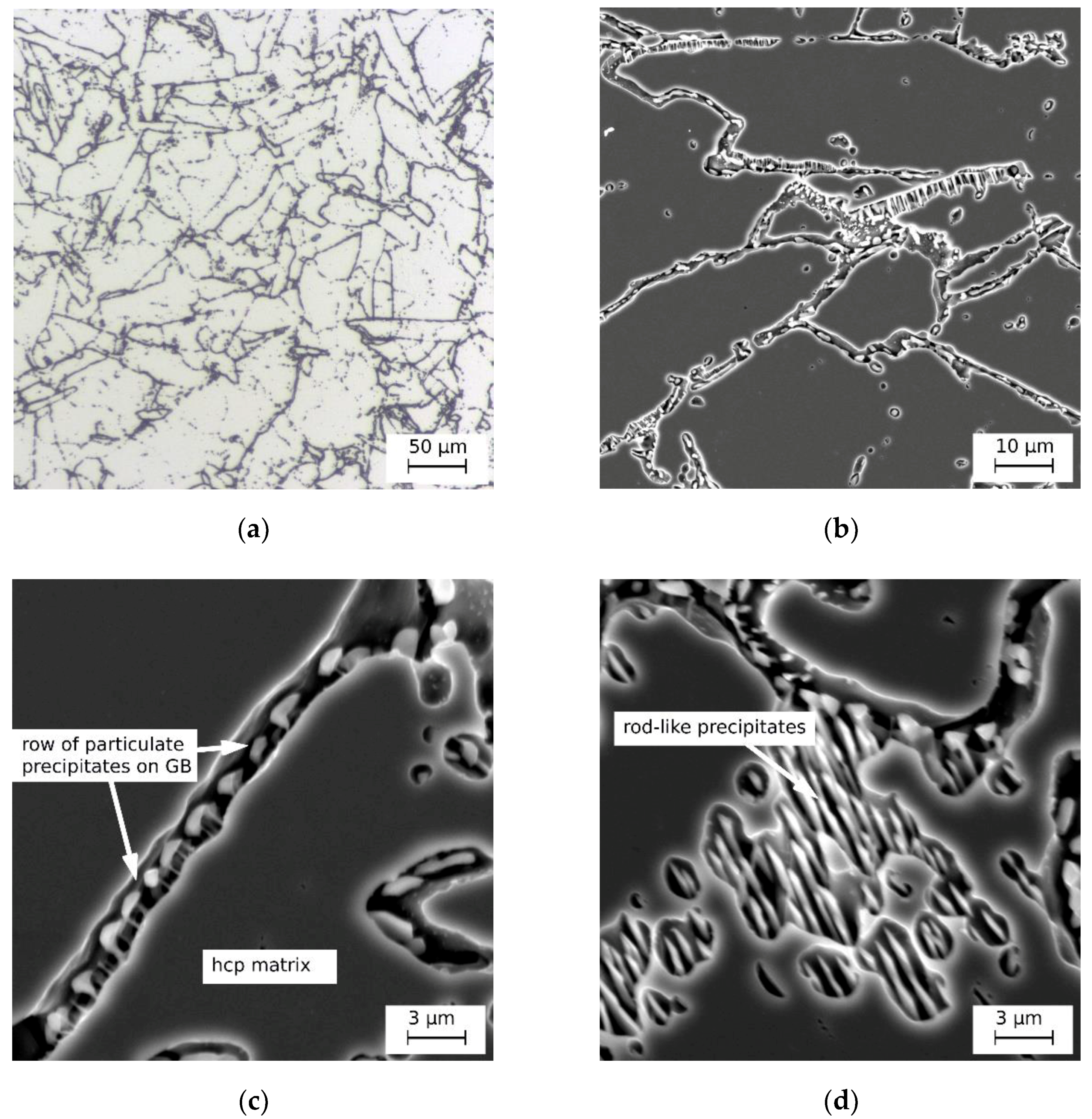
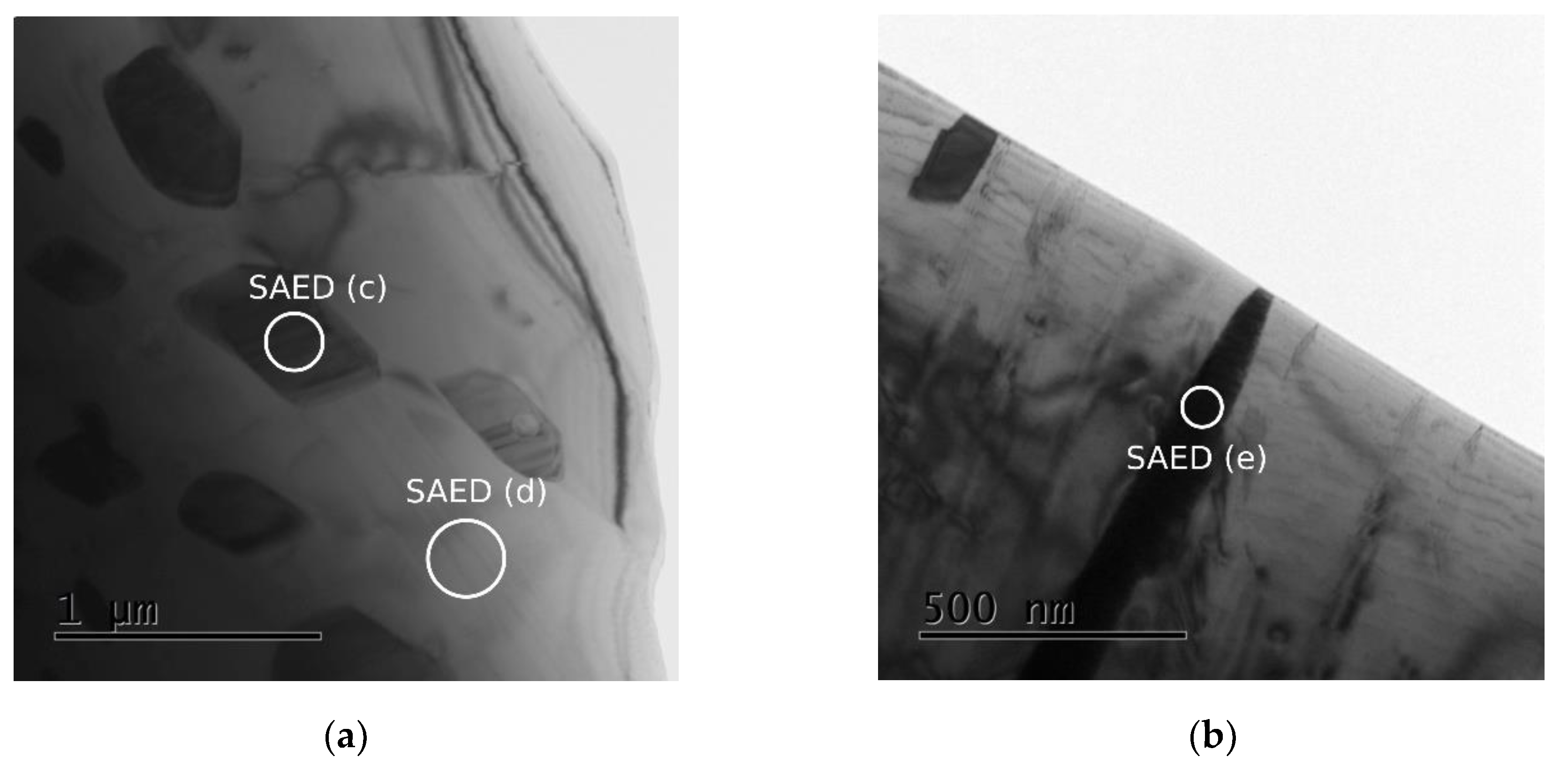
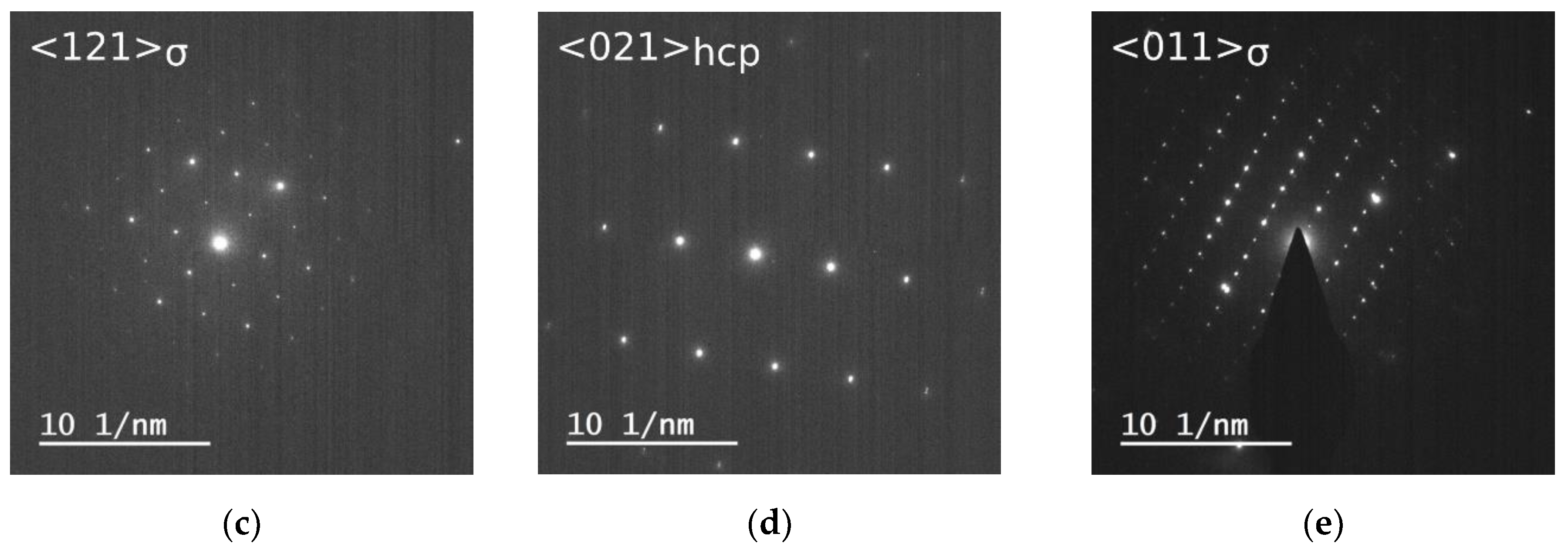
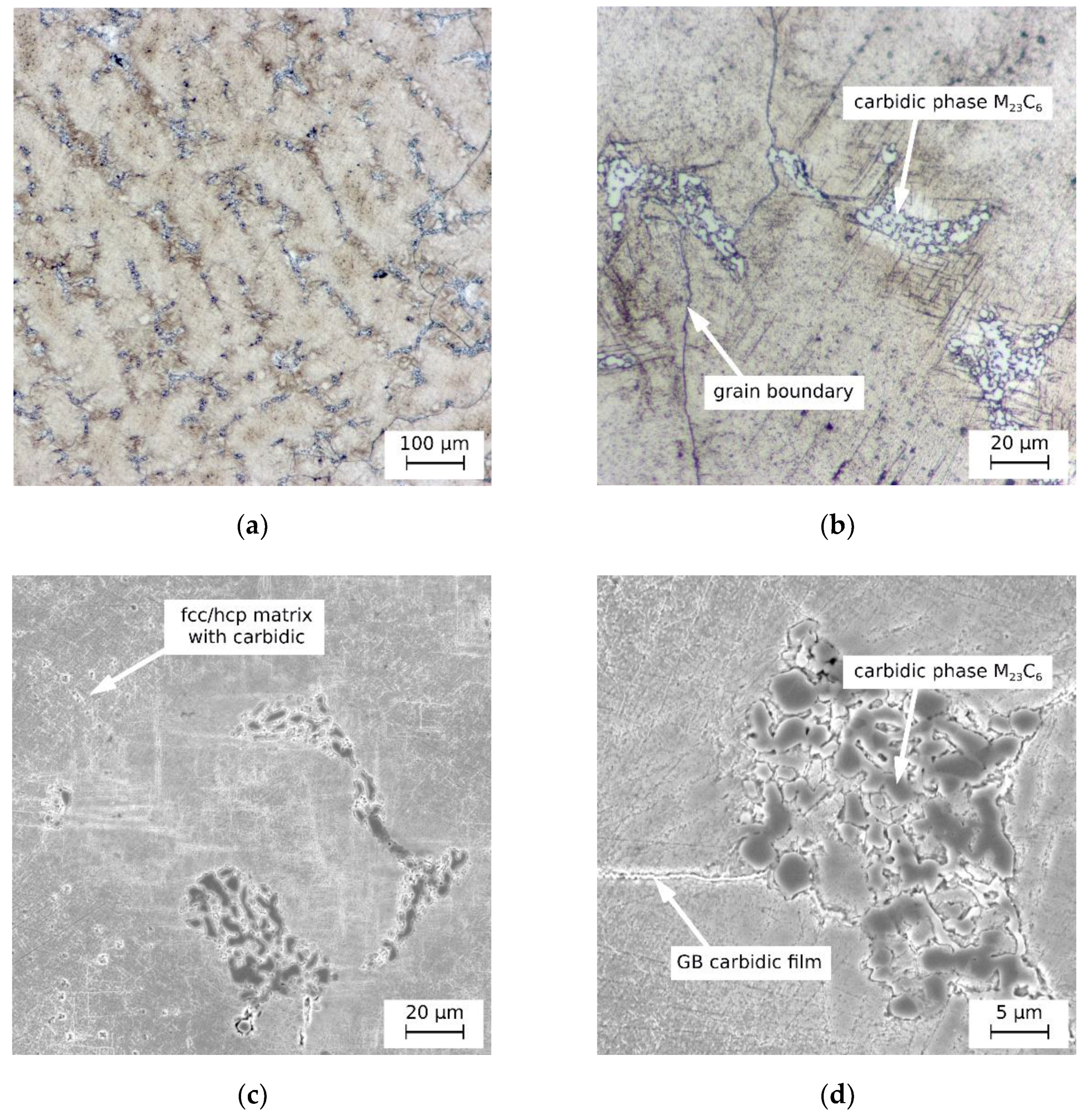
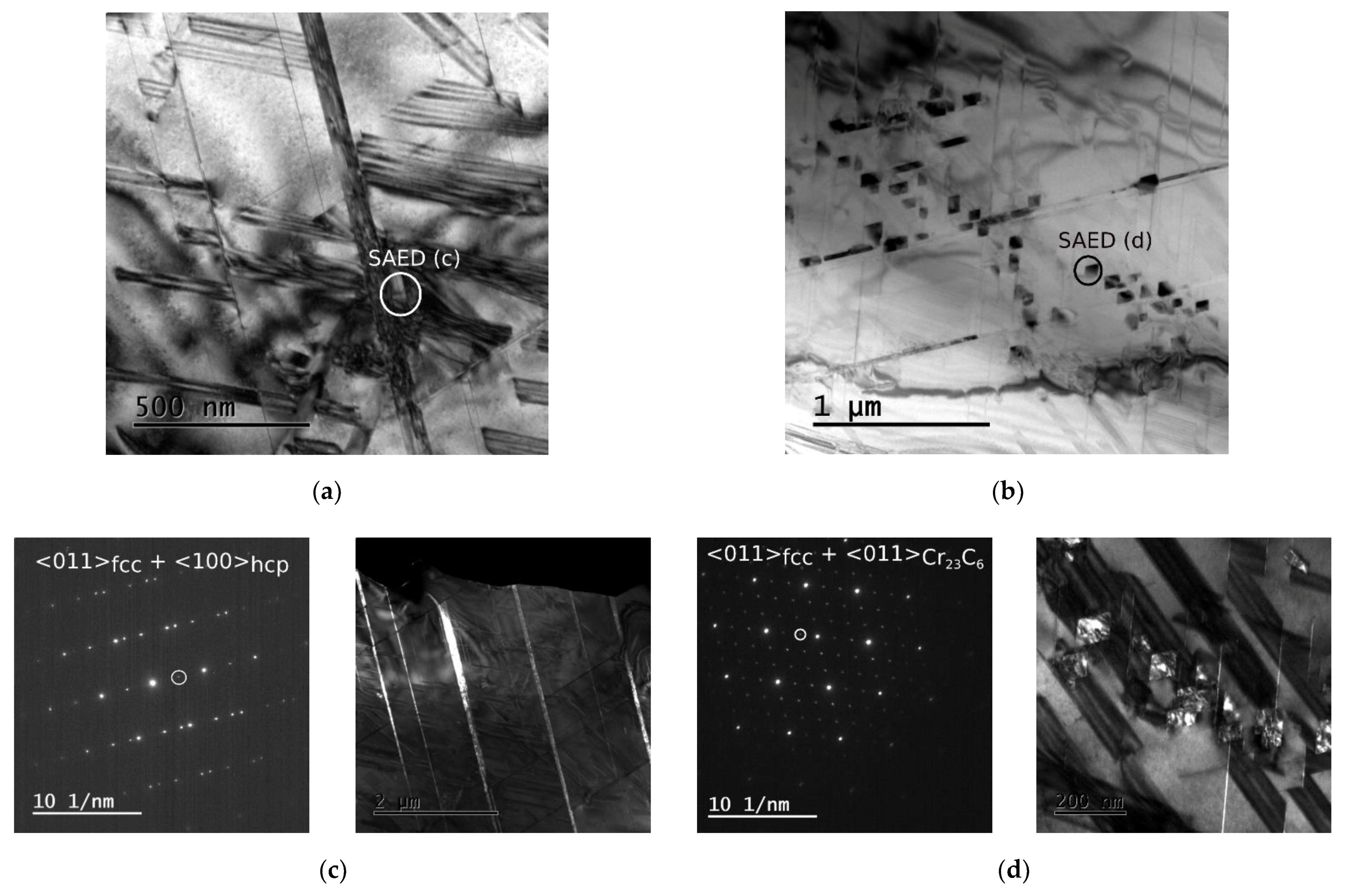
  • The dominant morphology is represented by relatively coarse carbidic particles (10–20 µm). However, a closer look (Figure 4c) reveals that it concerns domains containing very fine carbidic precipitates. According to TEM (Figure 5e), the grain size in these areas is about 150 nm. Laue diffraction patterns (Figure 5e) suggest that it concerns a mixture of M23C6 and M6C carbides along with some fcc Co-phase. Diffraction patterns of individual nanograins have shown predominantly the M23C6 carbides with a cubic structure with a lattice parameter of 0.107 nm (a representative diffraction pattern is shown in Figure 5d). Few nanograins showed fcc structure similar to the fcc matrix. As shown in Table 3, individual nanograins differ significantly in their chemical composition (C is excluded from the quantification as it cannot be reliably determined by EDS). In many of them, Cr was the dominant element (Points 2–5). Some (Point 1) showed the chemical composition similar to the composition of the Co matrix (Points 7, 8), thus being probably the same fcc phase as the matrix. Finally, there were some (Point 6) rich in Mo. Based on TEM-EDS analyses in 20 different nanograins, we grouped the obtained results for three phases whose chemical composition is summarized in Table 4. Phase 1, represented by 50% of all measured nanograins (10 out of 20), can be most probably assigned to M23C6 carbides rich in Cr; (Cr0.7Co0.2Mo0.1)23C6. Almost 40% of nanograins were then represented by Phase 2 with a composition similar to the fcc matrix (only slightly depleted of Cr). The remaining 10% contained a high amount of Mo (Phase 3). However, we were not able to distinguish the crystallography of this phase which could either be a Mo-rich M23C6-type carbide; (Mo0.4Co0.4Cr0.2)23C6, or a M6C-type carbide; (Mo0.4Co0.4Cr0.2)6C. Similar observations were reported by Liao et al. [38]. Liao et al. suggested that these nanograined domains contain a mixture of Co-rich and Mo-rich M23C6 carbides with some fcc phase as this mixture is more thermodynamically stable. They observed these mixed carbides after a slow cooling of 0.2 °C/s. At 50 °C/s, single-phase carbides were formed.
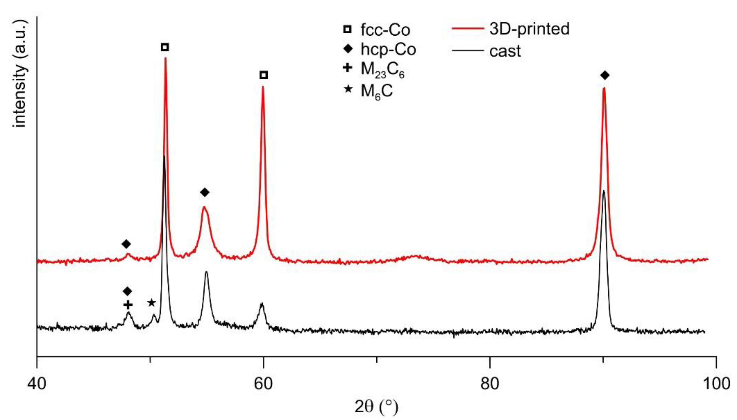
  • The second morphology is lamellar. The lamellar carbide morphology occurs in the areas adjacent to the nano-carbidic domains. These lamellar domains appear as dark areas in Figure 4a,b. The origin of this morphology remains unclear; some authors report a mixture of carbides (either M23C6 or M6C-type carbides) and fcc Co-phase of a eutectic origin [39], while others talk about eutectoid precipitation [40,41]. Ramirez et al. [42] observed that σ phase formed at the end of solidification range around 1200 °C as a binary eutectic with γ-fcc Co-phase. However, further cooling led metastable σ to transform into stable M23C6 carbide. The σ transformation occurs during slow cooling below 1150 °C by reaction with C; σ + C → M23C6 [40,41]. As XRD did not prove the presence of σ (content below the detection limit) in this work, its decomposition was almost complete so that alternating lamellae of γ-fcc and M23C6 can be observed.
  • The third carbide morphology is the carbidic film at grain boundaries (Figure 4b) formed by M6C-type carbide. It is the stable carbide configuration for Co-Cr-Mo alloys with Mo content above 4 wt%. However, it may decompose into a fine dispersion of secondary M23C6 carbides during annealing [43].
Figure 6 presents the XRD diffraction patterns for both cast and 3D-printed alloys. In both materials, the Co matrix consisted of both γ-fcc and ε-hcp phases. The lattice parameters determined for the dominant fcc phase were a = 0.3577 nm and a = 0.3579 nm for the cast and 3D-printed alloy, respectively. The hcp phase in the cast alloy showed lattice parameters a = 0.2528 nm and c = 0.4121 nm, with c/a ratio of 1.63. In the 3D-printed alloy, the hcp phase had a similar c/a ratio with a = 0.2528 nm and c = 0.4128 nm. Similar lattice parameters for the SLMed CCM alloy were reported, e.g., by Bawane et al. [44], but hcp phase showed a slightly higher c/a ratio than in this work. A lower c/a ratio agrees well with the results of Barucca et al. [35]. Larger peak broadening in the 3D-printed material tells of a higher dislocation density. The high intensity of the peak at 2θ = 59.8° corresponding to γ(200) describes a {200} texture in the 3D-printed sample. The preferential growth of grains in the <100> crystallographic orientation parallel with the building direction was reported by several works [19,45,46].

3.2. Microstructure Changes with Increasing Temperature

Figure 7 shows the evolution of hardness with annealing for 4 h at different temperatures. With elevated temperatures, microstructural changes occur, yielding changes in hardness. For both cast and 3D-printed materials, hardness increases and drops after reaching the maximum. However, while the cast material is stable up to 700 °C, keeping the hardness value nearly constant, microstructural instability is manifested above 400 °C already. A difference also occurs for the temperature at which the maximal hardening was achieved. The maximum hardness of the cast material was reached at 800 °C after which the hardness dropped already. In the case of the 3D-printed material, hardness increased gradually up to 700 °C (~20 HV10/100 °C). A sharper increase occurred between 700 and 800 °C similarly to the cast material. However, hardness increased even further at 900 °C and then dropped. The total hardness increase (ΔHV10 = 118) was more significant than for the cast material (ΔHV10 = 61).
After finding the temperature of maximum hardening, both materials were annealed for 10 h at that temperature and hardness was measured every hour to construct the hardening curve (Figure 8). Different curve shapes for the cast and 3D-printed material suggest a different hardening mechanism. While hardness increased linearly with time in the cast material, a sharp increase occurred in the 3D-printed material during the first hour of annealing. In next hours, hardness increased further only gently and became approximately invariant after 5 h. In the cast material, hardness started to decrease again after reaching the maximum after 7 h of annealing.
Figure 9 indicates the microstructural changes during annealing at different temperatures regarding the phase composition. As visible, the evolution of hcp fraction in the Co matrix approximately reproduces the trend of the hardness evolution curve in Figure 7. Increasing the fraction of hcp phase is thus the main cause for the observed hardness increase. However, dissimilarly to the 3D-printed material, the curve showing the evolution of hcp fraction (Figure 9) is slightly varied compared to the hardness evolution curve (Figure 7) at temperatures of 900 and 1000 °C. The cause of this variation is the presence of carbides, which play a significant role in material hardening besides the hcp fraction in the matrix. In the cast microstructure, the amount of carbides evolves in line with the evolution of hcp fraction up to 800 °C. At 900 °C, both the hcp fraction and the amount of carbides become already reduced. Such change thus yields a drop in hardness. At the temperature of 1000 °C (above Tc), in the γ-fcc stability area, the hcp phase is strongly suppressed. However, hardness kept un unchanged value due to the contradictory beneficial effect of carbides precipitated in a high amount. Compared to cast microstructure, a secondary phase that appears in the microstructure of the 3D-printed alloy is a tetragonal σ-phase. This phase was first precipitated at 800 °C, its amount was then significantly enhanced at 900 °C and decreased at 1000 °C. It seems that σ-phase does not contribute to hardness as much as carbides.

3.3. Heat Treatment

Based on the results of the experiments presented in Section 3.2, heat treatment was carried out. After the applied solution annealing (1200 °C/2 h), both materials were aged at conditions providing the maximum hardening: 800 °C/7 h for the cast alloy and 900 °C/5 h for the 3D-printed alloy.
In the 3D-printed microstructure (Figure 10), the solution annealing led to a complete disappearance of all macrostructural features. Columnar grains recrystallized; new more or less equiaxed grains of ~30 µm in diameter were formed. The fcc → hcp transformation was almost complete (92%), yielding the total hcp fraction of 97%. The cellular microstructure dissolved. Instead, 4% of σ precipitates were formed, predominantly at grain boundaries. This phase forms either spherical particles of about ~0.8 µm in size, or rod-like particles perpendicular to the grain boundary. TEM diffraction (Figure 11) attributed both the particle types to the M23C6-type carbides. This approximately equimolar intermetallic phase was enriched by Mo which partially substituted Cr; Co(Cr0.8Mo0.2).
Microstructure changes after annealing the cast alloy are shown in Figure 12. The heat treatment did not remove the dendritic nature of the microstructure due to the carbides present in the interdendritic areas. The carbides changed their morphology and coarsened. The areas of lamellar mixture M23C6 + γ-hcp and domains of mixed carbidic nanoprecipitates disappeared completely. Instead, agglomerations of spheroidized carbide particles (~6 µm) appeared. These carbides contained 54.4 ± 4.0 wt% of Cr, 15.2 ± 1.4 wt% of Mo and 15. 1 ± 1.9 wt% of Co. The chemical composition of the matrix remained comparable to the initial cast state (Table 2). Furthermore, TEM revealed nano-sized blocky carbides precipitated in the Co matrix (Figure 13a), which can be mostly attributed to M23C6-type carbides according to the diffraction pattern. TEM-EDS point analyses showed a similar composition as for the large carbides at grain boundaries. XRD confirmed that the M6C carbides present at grain boundaries transformed completely to M23C6 carbides. The total volume fraction of carbides increased by almost 10% due to fine carbides precipitated out from the Co matrix (dendrite interiors). The Co matrix was transformed to hcp phase from 22%. Isothermally transformed martensitic needles, homogeneously distributed in the matrix, are visible in the microstructure by SEM already (Figure 12b). The TEM image in Figure 13b shows the hcp lamellae in the fcc matrix, nucleated at SFs, the density of which significantly increased after the aging treatment.
Figure 14 depicts the impact of the applied heat treatment on the material hardness. In both cast and 3D-printed materials, the hardness was increased. The hardness of the 3D-printed alloy in its as-built state exceeds the hardness of the cast alloy by 17%. Higher hardness can be attributed to finer grain size and the higher density of dislocations arranged in the cellular network (Figure 1 and Figure 2). Further hardness increase with heat treatment by 15% can be mainly associated with the massive transformation providing fully hcp grains. Saldívar Garcia et al. [47] reported a 50% increase when transforming a completely fcc matrix to a completely hcp one. However, the dissolution of the dislocation structure and reduction of the dislocation density compared to the as-built state have an adverse effect on hardness; thus, its increase is weakened. The contribution of σ precipitates on grain boundaries is only minor. The heat treatment of the cast alloy was more successful in increasing its hardness (by 24%) due to the fine carbides precipitated throughout the Co matrix and increased density of SFs.

4. Discussion

4.1. Initial Microstructure

A significant difference between the microstructures of the Co-28Cr-6Mo alloy prepared by investment casting and SLM stems from the enormous difference in cooling rates (up to 108 °C/s for SLM compared to 100–102 °C/s for casting) as well as a different thermal history. SLM as a 3D-printing technique is a layer-wise process in which small volumes of powdered material are melted by a laser beam spot. As the laser moves in its scanning direction, these melt pools solidify almost instantly. However, due to the additive principle of SLM, solidified melt pools are influenced multiple times by the processing of adjacent areas. The solidified melt pools are partially remelted by the laser melting of adjacent melt pools in the same layer as well as by melting the powder deposited on top of the already solidified layer. Except from the partial remelting and repeated solidification, the material is thermally affected by heat produced during the processing of several subsequent layers [25].
The cooling rate determines the solidification mechanism. While slow cooling during casting yield dendritic solidification (Figure 4a), cellular solidification occurs during extreme cooling rates of SLM (Figure 1d). Although some materials undergo the cellular eutectic solidification with the eutectics solidified in the form of the intercellular network [30,48,49,50], the SLMed CCM alloy studied in this work showed a dislocation cellular structure within a single Co-phase with Mo segregation on the dislocation walls (Figure 2). Only a negligible amount of σ-phase was precipitated in the intercellular network. A similar observation is reported in [51], where enrichment in Mo was measured on cell boundaries but without any precipitates observed. Takaichi et al. [11] observed more abundant σ-precipitates in the cellular network, probably due to much higher energy applied during laser melting. Although both the prepared 3D-printed alloy and the purchased cast alloy satisfied the chemical composition given by the ASTM F75 standard, we analyzed a low amount of C in the 3D-printed material compared to the cast material. Some works in which C was present [33,50,52] reported the presence of carbide precipitates in the intercellular network instead of Mo segregation on dislocation walls or σ precipitates that we observed.
Rapid cooling also influences phase transformations during solidification. High-temperature phases thus often remain in the microstructure or another metastable phases are formed [53]. In this sense, Co-Cr-Mo alloys behave in a specific manner as the transformation of high-temperature γ-fcc phase to low-temperature ε-hcp phase is very sluggish so that it occurs to a limited extent even during slow cooling; metastable γ-fcc phase is thus kept in the microstructure as the prevalent phase [20]. Athermal transformation is reported to occur up to 15% in maximum [54]. Castings usually show 0–10% of the hcp phase [20,41]. Rapid cooling during SLM enhances the athermal transformation, plus there is the consecutive effect of in-situ isothermal annealing originating from heat affection during layer-wise processing. More hcp phase can be thus nucleated in the solidified material. Moreover, lower C content might influence the amount of hcp phase as C increases the stacking fault energy. With lower C content, stacking faults which serve as nucleation sites (Figure 3c) are generated in a greater number, thus promoting the hcp transformation [55]. We determined 28% of ε-hcp phase in the as-built material. The slowly cooled cast alloy showed approximately the same amount of ε-hcp phase due to the isothermal heat treatment carried out by the supplier.
In literature, the reported contents of hcp phase in the SLMed CCM alloy vary significantly among different authors. Many of the works [18,56,57] detected only fcc Co-phase, which they attribute to high cooling rates during SLM. However, other works [9,44,50] have reported a certain content of hcp phase as we did. Bawane et al. [44] stated a little lower content of ε-hcp of about 20%. Zhang et al. [50] reported a similar content of ~30%. Moreover, a work (Wang et al. [10]) appeared in which ε-hcp phase was the dominant one (95%). Observed differences may arise from different processing parameters as well as from the difficulty in exact determination of the martensitic phase [9].

4.2. Microstructure Changes with Increasing Temperature

The cast and 3D-printed alloy showed somewhat different behavior when studying hardness changes during annealing at increasing temperatures (Figure 7 and Figure 8). As confirmed by XRD (Figure 9), the main hardening contribution can be attributed to the increasing amount of ε-hcp phase. What differs is the onset of γ-fcc → ε-hcp transformation. While the cast microstructure was shown to be stable up to 700 °C (almost unchanged hcp fraction), the isothermal transformation in the 3D-printed material occurred already above 400 °C. The continuously increasing amount of hcp phase yielded a gradual increase in hardness by generating hcp needles in the fcc matrix by isothermal transformation. A sharper increase was observed for 800 and 900 °C. As was studied in our previous paper [36] as well as by Donkor et al. [58], the sudden sharp increase is associated with the massive transformation which replaced the isothermal transformation at these temperatures. During the massive transformation, new hcp grains are nucleated on grain boundaries of original grains and gradually consume them by a diffusional growth. The massive transformation at 800 and 900 °C yielded a matrix represented by ~70 and 80% of ε-hcp, respectively [36]. As metastable ε1 phase with excess Cr is formed first, it subsequently decomposes by discontinuous reaction into stable ε2 phase and σ precipitates [59]. The rapid course of massive transformation can be represented by the curve of hardness evolution in time in Figure 8. Most of the matrix was transformed within the first hour of annealing.
In the cast material, the fcc → hcp transformation is generally restricted by the presence of carbides which deplete the Co matrix by Cr and Mo and thus stabilize the fcc phase by increasing the stacking fault energy. Isothermal martensitic transformation occurs at elevated temperatures up to Tc. It starts with localized autocatalytic martensite nucleation events in the neighborhood of carbidic domains due to the reduced nucleation energy and then the amount of hcp in the fcc matrix continuously evolves with time (Figure 8). Intrinsic SFs act as hcp embryos because the motion of Shockley partials on every alternate plane yields a bulk hcp phase. CCM alloys willingly produce fcc SFs due to low stacking fault energy. The higher the annealing temperature, the more SFs develop [20]. The simultaneous precipitation of carbides occurs, resulting in a lamellar “pearlitic” morphology. Carbon solutes diffuse away from the developed martensite, as there is hardly any solubility of C in the hcp-Co. The formation of interphase carbides is thus promoted. Although the martensitic displacive transformation is expected to be extremely fast, it is limited by the availability of hcp embryos. It can be also stopped by the buildup of hcp/fcc interfacial stresses preventing SFs from extension [20]. As represented by the curve in Figure 8, the growth of hcp phase by the isothermal transformation is much more gradual than in the massively transformed 3D-printed microstructure, as it requires rearrangement of atomic planes by reactions of partial dislocations [60]. Although the massive transformation did not occur, a similar sudden increase in hcp fraction up to 70–80% was registered for the temperatures of 800 and 900 °C (Figure 9). This can be explained by the maximum nucleation rates which have been determined to occur between 820 and 870 °C [47]. A lower fcc → hcp conversion at 900 °C is probably caused by an increased embryo size due to which fewer stable nuclei can be formed.

4.3. Heat Treatment

Heat treatment consisting of solution annealing and aging confirmed the different microstructure evolution. In the 3D-printed material, the features associated with the SLM manufacturing disappeared after solution annealing; microstructure with Mo segregations homogenized and columnar grains recrystallized. Further aging at 900 °C/5 h brought transformation of recrystallized fcc grains by massive transformation into fully hcp grains. Particles of σ phase nucleated along grain boundaries (Figure 10). A similar microstructure change was observed by Zhang et al. [50], who studied the heat treatment of a C-containing (0.15 wt%) SLMed CCM alloy with the main difference being the precipitation of carbides along grain boundaries instead of σ phase. About 90% of hcp phase was formed after 6 h of annealing at 900 °C. A measured 15% increase in hardness can be attributed to the present hcp phase with a limited number of slip systems compared to the fcc phase [34].
In the cast material, the initial dendritic microstructure was preserved due to present carbides which prevent recrystallization. Nevertheless, annealing in the fcc stability region ensured the material was completely fcc. Solution annealing caused the coalescence of nanoprecipitates of M23C6-type carbides in the original interdendritic carbidic domains and formation of large spherical carbide particles (Figure 12c). High temperature led to the transformation of M6C carbides in the grain boundary film. During subsequent quenching, some athermal martensite could be formed. However, the higher the content of C acting as a γ-stabilizer, the more suppressed the athermal martensitic transformation is [55]. A high density of SFs appeared in the fcc matrix during aging, serving as nucleation sites for the isothermal transformation γ-fcc → ε-hcp (Figure 13b). However, such transformation is limited; aging for 7 h resulted in the ε-hcp fraction of 22%. López and García [20] reported that 28 h is necessary to achieve full transformation at 800 °C. Along with the nucleation of hcp needles, carbidic precipitates with tens of nanometers in size appeared homogeneously distributed between the hcp needles inside the grains (Figure 13a). As there is a negligible solubility of C in the hcp-Co, C diffuses away from the formed hcp phase and its interface segregation subsequently results in the formation of interphase carbides. The concomitant growth of carbides at the hcp/fcc interface is a highly coordinated process. As strains can develop at the hcp/carbide/fcc interfaces, a growth of carbides minimizing the energy barriers associated with lattice mismatches is favored [20]. Therefore, M23C6-type carbides of the fcc type with a similar lattice parameter to fcc Co are formed (Figure 13d). They obtain cuboid shapes, as their growth is limited by the fcc/hcp interfaces. These nanoprecipitates play a significant role in material strengthening, hindering dislocation slip. The observed 24% increase in hardness is thus attributed to the mutual effect of the increased density of hcp/fcc interfaces and carbidic nanoprecipitates.

5. Conclusions

The direct comparison between Co-28Cr-6Mo alloy prepared conventionally by investment casting and the one prepared using a 3D-printing technique SLM presented in this study has demonstrated that the alloy shows a similar response of hardness measurement to annealing at different temperatures despite a significant difference in the initial microstructure state. However, the observed changes in material hardness are the result of different microstructural changes. While massive transformation at 800–900 °C yielded a recrystallized microstructure with fully hcp grains in the 3D-printed material and precipitated particles of σ-phase, dendritic microstructure was preserved in the cast material in which lamellar hcp phase created by isothermal martensitic transformation appeared in the original fcc Co matrix with extended carbidic domains. Similar hcp fractions were obtained.
However, the heat treatment in which high-temperature solution annealing preceded the isothermal annealing below Tc yielded a completely different microstructure evolution. Solution annealing converted the cast material into a single fcc phase and significantly limited the subsequent isothermal fcc→hcp transformation. Only 22% of lamellar hcp phase was generated in the dendritic matrix during the aging that followed. Compared to that, recrystallized 3D-printed microstructure showed 97% of hcp due to the massive transformation. In terms of increasing the wear resistance of the CCM alloy intended for knee or hip implants by enhancing the hcp-Co phase, the applied heat treatment was thus successful only for the 3D-printed material. Studying the wear behavior should thus follow, also covering the effects of different secondary phases in the Co matrix (σ phase at grain boundaries of the 3D-printed material, different morphologies of M23C6 carbides in the cast material).

Author Contributions

Conceptualization, M.R. and D.V.; methodology, D.P. and M.R.; investigation, J.B. and O.M.; resources, D.P. and D.V.; data curation, M.R.; writing—original draft preparation, M.R.; writing—review and editing, M.R.; supervision, D.V.; funding acquisition, M.R., D.P. and D.V. All authors have read and agreed to the published version of the manuscript.

Funding

This research on the part of University of Chemistry and Technology Prague was funded by the Czech Ministry of Education, Youth and Sports, grant numbers A2_FCHT_2020_026 and A1_FCHT_2020_003. The research on the part of Brno University of Technology was funded by the Czech Ministry of Education, Youth and Sports, grant numbers CZ.02.1.01/0.0/0.0/16_025/0007304 and FSI-S-20-6296. The research work carried out by Orsolya Molnarova was funded by MEYS CR, grant number LM2018110.

Data Availability Statement

The data presented in this study are available on request from the corresponding author.

Conflicts of Interest

The authors declare no conflict of interest. The funders had no role in the design of the study; in the collection, analyses, or interpretation of data; in the writing of the manuscript, or in the decision to publish the results.

References

  1. Haan, J.; Asseln, M.; Zivcec, M.; Eschweiler, J.; Radermacher, R.; Broeckmann, C. Effect of subsequent Hot Isostatic Pressing on mechanical properties of ASTM F75 alloy produced by Selective Laser Melting. Powder Metall. 2015, 58, 161–165. [Google Scholar] [CrossRef]
  2. Fleming, T.J.; Kavanagh, A.; Duggan, G.; O’Mahony, B.; Higgens, M. The effect of induction heating power on the microstructural and physical properties of investment cast ASTM-F75 CoCrMo alloy. J. Mater. Res. Technol. 2019, 8, 4417–4424. [Google Scholar] [CrossRef]
  3. Zaman, H.A.; Sharif, S.; Kim, D.-W.; Idris, M.H.; Suhaimi, M.A.; Tumurkhuyag, Z. Machinability of cobalt-based and cobalt chromium molybdenum alloys—A review. Procedia Manuf. 2017, 11, 563–570. [Google Scholar] [CrossRef]
  4. Giacchi, J.V.; Morando, C.N.; Fornaro, O.; Palacio, H.A. Microstructural characterization of as-cast biocompatible Co–Cr–Mo alloys. Mater. Charact. 2011, 62, 53–61. [Google Scholar] [CrossRef]
  5. Wong, K.V.; Hernandez, A. A review of additive manufacturing. ISRN Mech. Eng. 2012, 2012, 208760. [Google Scholar] [CrossRef] [Green Version]
  6. Riva, L.; Ginestra, P.S.; Ceretti, E. Mechanical characterization and properties of laser-based powder bed–fused lattice structures: A review. Int. J. Adv. Manuf. Technol. 2021, 113, 649–671. [Google Scholar] [CrossRef]
  7. Liverani, E.; Fortunato, A.; Leardini, A.; Belvedere, C.; Siegler, S.; Ceschini, L.; Ascari, A. Fabrication of Co–Cr–Mo endoprosthetic ankle devices by means of Selective Laser Melting (SLM). Mater. Des. 2016, 106, 60–68. [Google Scholar] [CrossRef]
  8. AlMangour, B.; Luqman, M.; Grzesiak, D.; Al-Harbi, H.; Ijaz, F. Effect of processing parameters on the microstructure and mechanical properties of Co–Cr–Mo alloy fabricated by selective laser melting. Mater. Sci. Eng. A 2020, 792, 139456. [Google Scholar] [CrossRef]
  9. Tonelli, L.; Fortunato, A.; Ceschini, L. CoCr alloy processed by Selective Laser Melting (SLM): Effect of Laser Energy Density on microstructure, surface morphology, and hardness. J. Manuf. Process. 2020, 52, 106–119. [Google Scholar] [CrossRef]
  10. Wang, Z.; Tang, S.Y.; Scudino, S.; Ivanov, Y.P.; Qu, R.T.; Wang, D.; Yang, C.; Zhang, W.W.; Greer, A.L.; Eckert, J.; et al. Additive manufacturing of a martensitic Co–Cr–Mo alloy: Towards circumventing the strength–ductility trade-off. Addit. Manuf. 2021, 37, 101725. [Google Scholar] [CrossRef]
  11. Takaichi, A.; Suyalatu; Nakamoto, T.; Joko, N.; Nomura, N.; Tsutsumi, Y.; Migita, S.; Doi, H.; Kurosu, S.; Chiba, A.; et al. Microstructures and mechanical properties of Co–29Cr–6Mo alloy fabricated by selective laser melting process for dental applications. J. Mech. Behav. Biomed. Mater. 2013, 21, 67–76. [Google Scholar] [CrossRef]
  12. Kim, K.-S.; Hwang, J.-W.; Lee, K.-A. Effect of building direction on the mechanical anisotropy of biocompatible Co–Cr–Mo alloy manufactured by selective laser melting process. J. Alloys Compd. 2020, 834, 155055. [Google Scholar] [CrossRef]
  13. Xiang, D.D.; Wang, P.; Tan, X.P.; Chandra, S.; Wang, C.; Nai, M.L.S.; Tor, S.B.; Liu, W.Q.; Liu, E. Anisotropic microstructure and mechanical properties of additively manufactured Co–Cr–Mo alloy using selective electron beam melting for orthopedic implants. Mater. Sci. Eng. A 2019, 765, 138270. [Google Scholar] [CrossRef]
  14. Kajima, Y.; Takaichi, A.; Kittikundecha, N.; Htat, H.L.; Cho, H.H.W.; Tsutsumi, Y.; Hanawa, T.; Wakabayashi, N.; Yoneyama, T. Reduction in anisotropic response of corrosion properties of selective laser melted Co–Cr–Mo alloys by post-heat treatment. Dent. Mater. 2021, 37, e98–e108. [Google Scholar] [CrossRef]
  15. Dong, X.; Sun, Q.; Zhou, Y.; Qu, Y.; Shi, H.; Zhang, B.; Xu, S.; Liu, W.; Li, N.; Yan, J. Influence of microstructure on corrosion behavior of biomedical Co-Cr-Mo-W alloy fabricated by selective laser melting. Corros. Sci. 2020, 170, 108688. [Google Scholar] [CrossRef]
  16. Dong, X.; Zhou, Y.; Sun, Q.; Qu, Y.; Shi, H.; Liu, W.; Peng, H.; Zhang, B.; Xu, S.; Yan, J.; et al. Fatigue behavior of biomedical Co–Cr–Mo–W alloy fabricated by selective laser melting. Mater. Sci. Eng. A 2020, 795, 140000. [Google Scholar] [CrossRef]
  17. Xin, X.Z.; Xiang, N.; Chen, J.; Wei, B. In vitro biocompatibility of Co–Cr alloy fabricated by selective laser melting or traditional casting techniques. Mater. Lett. 2012, 88, 101–103. [Google Scholar] [CrossRef]
  18. Kajima, Y.; Takaichi, A.; Kittikundecha, N.; Nakamoto, T.; Kimura, T.; Nomura, N.; Kawasaki, A.; Hanawa, T.; Takahashi, H.; Wakabayashi, N. Effect of heat-treatment temperature on microstructures and mechanical properties of Co–Cr–Mo alloys fabricated by selective laser melting. Mater. Sci. Eng. A 2018, 726, 21–31. [Google Scholar] [CrossRef]
  19. Takaichi, A.; Kajima, Y.; Kittikundecha, N.; Htat, H.L.; Wai Cho, H.H.; Hanawa, T.; Yoneyama, T.; Wakabayashi, N. Effect of heat treatment on the anisotropic microstructural and mechanical properties of Co–Cr–Mo alloys produced by selective laser melting. J. Mech. Behav. Biomed. Mater. 2020, 102, 103496. [Google Scholar] [CrossRef]
  20. López, H.F.; Saldivar-Garcia, A.J. Martensitic Transformation in a Cast Co-Cr-Mo-C Alloy. Metall. Mater. Trans. A 2008, 39, 8–18. [Google Scholar] [CrossRef]
  21. Balagna, C.; Spriano, S.; Faga, M.G. Characterization of Co–Cr–Mo alloys after a thermal treatment for high wear resistance. Mater. Sci. Eng. C 2012, 32, 1868–1877. [Google Scholar] [CrossRef] [Green Version]
  22. Saldívar-García, A.J.; López, H.F. Microstructural effects on the wear resistance of wrought and as-cast Co-Cr-Mo-C implant alloys. J. Biomed. Mater. Res. A 2005, 74A, 269–274. [Google Scholar] [CrossRef]
  23. Hassani, F.Z.; Ketabchi, M.; Bruschi, S.; Ghiotti, A. Effects of carbide precipitation on the microstructural and tribological properties of Co–Cr–Mo–C medical implants after thermal treatment. J. Mater. Sci. 2016, 51, 4495–4508. [Google Scholar] [CrossRef]
  24. Huang, P.; Salinas-Rodriguez, A.; López, H.F. Tribological behaviour of cast and wrought Co–Cr–Mo implant alloys. Mater. Sci. Technol. 1999, 15, 1324–1330. [Google Scholar] [CrossRef]
  25. Herzog, D.; Seyda, V.; Wycisk, E.; Emmelmann, C. Additive manufacturing of metals. Acta Mater. 2016, 117, 371–392. [Google Scholar] [CrossRef]
  26. Toh, W.Q.; Tan, X.; Bhowmik, A.; Liu, E.; Tor, S.B. Tribochemical Characterization and Tribocorrosive Behavior of CoCrMo Alloys: A Review. Materials 2018, 11, 30. [Google Scholar] [CrossRef] [Green Version]
  27. Tan, X.P.; Wang, P.; Kok, Y.; Toh, W.Q.; Sun, Z.; Nai, S.M.L.; Descoins, M.; Mangelinck, D.; Liu, E.; Tor, S.B. Carbide precipitation characteristics in additive manufacturing of Co-Cr-Mo alloy via selective electron beam melting. Scr. Mater. 2018, 143, 117–121. [Google Scholar] [CrossRef]
  28. Li, H.; Wang, M.; Lou, D.; Xia, W.; Fang, X. Microstructural features of biomedical cobalt–chromium–molybdenum (CoCrMo) alloy from powder bed fusion to aging heat treatment. J. Mater. Sci. Technol. 2020, 45, 146–156. [Google Scholar] [CrossRef]
  29. Yap, C.Y.; CHua, C.K.; Dong, Z.L.; Liu, Z.H.; Zhang, D.Q.; Loh, L.E.; Sing, S.L. Review of selective laser melting: Materials and applications. Appl. Phys. Rev. 2015, 2, 041101. [Google Scholar] [CrossRef]
  30. Fousova, M.; Dvorsky, D.; Vronka, M.; Vojtech, D.; Lejcek, P. The Use of Selective Laser Melting to Increase the Performance of AlSi9Cu3Fe Alloy. Materials 2018, 11, 1918. [Google Scholar] [CrossRef] [Green Version]
  31. Prashanth, K.G.; Eckert, J. Formation of metastable cellular microstructures in selective laser melted alloys. J. Alloys Compd. 2017, 707, 27–34. [Google Scholar] [CrossRef]
  32. Pinomaa, T.; Lindroos, M.; Walbrühl, M.; Provatas, N.; Laukkanen, A. The significance of spatial length scales and solute segregation in strengthening rapid solidification microstructures of 316L stainless steel. Acta Mater. 2020, 184, 1–16. [Google Scholar] [CrossRef]
  33. Song, C.; Zhang, M.; Yang, Y.; Wang, D.; Jia-kuo, Y. Morphology and properties of CoCrMo parts fabricated by selective laser melting. Mater. Sci. Eng. A 2018, 713, 206–213. [Google Scholar] [CrossRef]
  34. Béreš, M.; Silva, C.C.; Sarvezuk, P.W.C.; Wu, L.; Antunes, L.H.M.; Jardini, A.L.; Feitosa, A.L.M.; Žilková, J.; de Abreu, H.F.G.; Filho, R.M. Mechanical and phase transformation behaviour of biomedical Co-Cr-Mo alloy fabricated by direct metal laser sintering. Mater. Sci. Eng. A 2018, 714, 36–42. [Google Scholar] [CrossRef]
  35. Barucca, G.; Santecchia, E.; Majni, G.; Girardin, E.; Bassoli, E.; Denti, L.; Gatto, A.; Iuliano, L.; Moskalewicz, T.; Mengucci, P. Structural characterization of biomedical Co–Cr–Mo components produced by direct metal laser sintering. Mater. Sci. Eng. C 2015, 48, 263–269. [Google Scholar] [CrossRef] [Green Version]
  36. Roudnicka, M.; Molnarova, O.; Drahokoupil, J.; Kubasek, J.; Bigas, J.; Sreibr, V.; Palousek, D.; Vojtech, D. Microstructural instability of L-PBF Co28Cr6Mo alloy at elevated temperatures. Addit. Manuf. 2021. under review. [Google Scholar]
  37. Hitzler, L.; Alifui-Segbaya, F.; Williams, P.; Heine, B.; Heitzmann, M.; Hall, W.; Merkel, M.; Öchsner, A. Additive Manufacturing of Cobalt-Based Dental Alloys: Analysis of Microstructure and Physicomechanical Properties. Adv. Mater. Sci. Eng. 2018. article ID 8213023. [Google Scholar] [CrossRef] [Green Version]
  38. Liao, Y.; Pourzal, R.; Stemmer, P.; Wimmer, M.A.; Jacobs, J.J.; Fischer, A.; Marks, L.D. New insights into hard phases of CoCrMo metal-on-metal hip replacements. J. Mech. Behav. Biomed. Mater. 2012, 12, 39–49. [Google Scholar] [CrossRef] [PubMed] [Green Version]
  39. Varano, R.; Bobyn, J.D.; Medley, J.B.; Yue, S. The effect of microstructure on the wear of cobalt-based alloys used in metal-on-metal hip implants. Proc. Inst. Mech. Eng. H 2006, 220, 145–159. [Google Scholar] [CrossRef]
  40. Ramírez-Vidaurri, L.E.; Castro-Román, M.; Herrera-Trejo, M.; García-López, C.V.; Almanza-Casas, E. Cooling rate and carbon content effect on the fraction of secondary phases precipitate in as-cast microstructure of ASTM F75 alloy. J. Mater. Process. Technol. 2009, 209, 1681–1687. [Google Scholar] [CrossRef]
  41. Rosenthal, R.; Cardoso, B.R.; Bott, I.S.; Paranhos, R.P.R.; Carvalho, E.A. Phase characterization in as-cast F-75 Co–Cr–Mo–C alloy. J. Mater. Sci. 2010, 45, 4021–4028. [Google Scholar] [CrossRef]
  42. Ramıírez, L.E.; Castro, M.; Méndez, M.; Lacaze, J.; Herrera, M.; Lesoult, G. Precipitation path of secondary phases during solidification of the Co–25.5%Cr–5.5%Mo–0.26%C alloy. Scr. Mater. 2002, 47, 811–816. [Google Scholar] [CrossRef]
  43. Muterlle, P.V. Microstructural and Mechanical Properties of Co and Ti Alloys for Biomedical Applications Produced by Metal Injection Molding (MIM). Ph.D. Thesis, University of Trento, Trento, Italy, 2010. [Google Scholar]
  44. Bawane, K.K.; Srinivasan, D.; Banerjee, D. Microstructural Evolution and Mechanical Properties of Direct Metal Laser-Sintered (DMLS) CoCrMo After Heat Treatment. Metall. Mater. Trans. A 2018, 49, 3793–3811. [Google Scholar] [CrossRef]
  45. Zhou, X.; Li, K.; Zhang, D.; Liu, X.; Ma, J.; Liu, W.; Shen, Z. Textures formed in a CoCrMo alloy by selective laser melting. J. Alloys Compd. 2015, 631, 153–164. [Google Scholar] [CrossRef]
  46. Zhao, Y.; Koizumi, Y.; Aoyagi, K.; Wei, D.; Yamanaka, K.; Chiba, A. Comprehensive study on mechanisms for grain morphology evolution and texture development in powder bed fusion with electron beam of Co–Cr–Mo alloy. Materialia 2019, 6, 100346. [Google Scholar] [CrossRef]
  47. Saldívar García, A.d.J.; Medrano, A.M.; Rodríguez, A.S. Formation of hcp martensite during the isothermal aging of an fcc Co-27Cr-5Mo-0.05C orthopedic implant alloy. Metall. Mater. Trans. A 1999, 30, 1177–1184. [Google Scholar] [CrossRef]
  48. Liu, X.; Zhao, C.; Zhou, X.; Shen, Z.; Liu, W. Microstructure of selective laser melted AlSi10Mg alloy. Mater. Des. 2019, 168, 107677. [Google Scholar] [CrossRef]
  49. Tao, P.; Li, H.; Huang, B.; Hu, Q.; Gong, S.; Xu, Q. The crystal growth, intercellular spacing and microsegregation of selective laser melted Inconel 718 superalloy. Vacuum 2019, 159, 382–390. [Google Scholar] [CrossRef]
  50. Zhang, M.; Yang, Y.; Song, C.; Bai, Y.; Xiao, Z. An investigation into the aging behavior of CoCrMo alloys fabricated by selective laser melting. J. Alloys Compd. 2018, 750, 878–886. [Google Scholar] [CrossRef]
  51. Qian, B.; Saeidi, K.; Kvetková, L.; Lofaj, F.; Xiao, C.; Shen, Z. Defects-tolerant Co-Cr-Mo dental alloys prepared by selective laser melting. Dent. Mater. 2015, 31, 1435–1444. [Google Scholar] [CrossRef] [PubMed]
  52. Li, J.; Ren, H.; Liu, C.; Shang, S. The Effect of Specific Energy Density on Microstructure and Corrosion Resistance of CoCrMo Alloy Fabricated by Laser Metal Deposition. Materials 2019, 12, 1321. [Google Scholar] [CrossRef] [Green Version]
  53. Frazier, W.E. Metal Additive Manufacturing: A Review. J. Mater. Eng. Perform. 2014, 23, 1917–1928. [Google Scholar] [CrossRef]
  54. Saldívar García, A.d.J.; Maní Medrano, A.; Salinas Rodríguez, A. Effect of solution treatments on the FCC/HCP isothermal martensitic transformation in Co-27Cr-5Mo-0.05C aged at 800 °C. Scr. Mater. 1999, 40, 717–722. [Google Scholar] [CrossRef]
  55. Lee, S.-H.; Takahashi, E.; Nomura, N.; Chiba, A. Effect of Carbon Addition on Microstructure and Mechanical Properties of a Wrought Co–Cr–Mo Implant Alloy. Mater. Trans. 2006, 47, 287–290. [Google Scholar] [CrossRef] [Green Version]
  56. Antunes, L.H.M.; Hoyos, J.J.; Fonseca, E.B.; Béreš, M.; da Silva Farina, P.F.; Lopes, E.S.N.; Jardini, A.L.; Filho, R.M. Effect of phase transformation on ductility of additively manufactured Co–28Cr–6Mo alloy: An in situ synchrotron X-ray diffraction study during mechanical testing. Mater. Sci. Eng. A 2019, 764, 138262. [Google Scholar] [CrossRef]
  57. Sing, S.L.; Huang, S.; Yeong, W.Y. Effect of solution heat treatment on microstructure and mechanical properties of laser powder bed fusion produced cobalt-28chromium-6molybdenum. Mater. Sci. Eng. A 2020, 769, 138511. [Google Scholar] [CrossRef]
  58. Donkor, B.T.; Song, J.; Fu, Y.; Kattoura, M.; Mannava, S.R.; Steiner, M.A.; Vasudevan, V.K. Accelerated γ-face-centered cubic to ε-hexagonal close packed massive transformation in a laser powder bed fusion additively manufactured Co-29Cr-5Mo alloy. Scr. Mater. 2020, 179, 65–69. [Google Scholar] [CrossRef]
  59. Kurosu, S.; Matsumoto, H.; Chiba, A. Isothermal Phase Transformation in Biomedical Co-29Cr-6Mo Alloy without Addition of Carbon or Nitrogen. Metall. Mater. Trans. A 2010, 41, 2613–2625. [Google Scholar] [CrossRef]
  60. Vander Sande, J.B.; Coke, J.R.; Wulff, J. A transmission electron microscopy study of the mechanisms of strengthening in heat-treated Co-Cr-Mo-C alloys. Metall. Trans. A 1976, 7, 389–397. [Google Scholar] [CrossRef]
Figure 1. Initial microstructure of the 3D-printed Co-Cr-Mo alloy: (a) XY section (optical microscopy (OM) micrograph; (b,c) XZ section (OM); (d) scanning electron microscopy (SEM) micrograph.
Metals 11 00687 g001aMetals 11 00687 g001b
Figure 2. Chemical composition inside cells and in the intercellular network.
Metals 11 00687 g002
Figure 3. Transmission electron microscopy (TEM) observations of the initial microstructure of the 3D-printed Co-Cr-Mo alloy: (a) dislocation cells; (b) hcp lamellae; (c) nucleation of hcp lamellae at stacking faults, (d) selected area electron diffraction (SAED) pattern.
Metals 11 00687 g003aMetals 11 00687 g003b
Figure 4. Initial microstructure of the cast Co-Cr-Mo alloy: (a,b) OM; (c,d) SEM.
Metals 11 00687 g004
Figure 5. TEM observations of the initial microstructure of the cast Co-Cr-Mo alloy: (a) fcc matrix with hcp needles; (b) diffraction pattern for image (a); (c) domain of carbidic precipitates; (d) M23C6 carbide; (e) Laue diffraction patterns for image (c).
Metals 11 00687 g005aMetals 11 00687 g005b
Figure 6. X-ray diffraction (XRD) diffraction patterns of cast and 3D-printed Co-Cr-Mo alloy.
Metals 11 00687 g006
Figure 7. Hardness changes with increasing temperature.
Metals 11 00687 g007
Figure 8. Time hardness evolution during annealing (cast—800 °C; 3D-printed—900 °C).
Metals 11 00687 g008
Figure 9. Evolution of phase composition at selected temperatures: (a) hcp fraction in the matrix; (b) content of secondary phases.
Metals 11 00687 g009
Figure 10. Microstructure of the 3D-printed alloy after 1200 °C/2 h + 900 °C/5 h heat treatment: (a) OM; (bd) SEM.
Metals 11 00687 g010
Figure 11. Microstructure of the 3D-printed alloy after 1200 °C/2 h + 900 °C/5 h heat treatment: (a) TEM image of grain boundary precipitates; (b) TEM image of rod-like precipitates; (ce) diffraction patterns.
Metals 11 00687 g011aMetals 11 00687 g011b
Figure 12. Microstructure of the cast alloy after 1200 °C/2 h + 800 °C/7 h heat treatment: (a,b) OM; (c,d) SEM.
Metals 11 00687 g012
Figure 13. Microstructure of the cast alloy after 1200 °C/2 h + 800 °C/7 h heat treatment: (a) TEM image of the matrix; (b) TEM image of carbidic precipitates; (c,d) diffraction pattern with dark field image based on a selected diffraction point.
Metals 11 00687 g013
Figure 14. Hardness changes after heat treatment.
Metals 11 00687 g014
Table 1. Chemical composition (wt%) of the studied Co-28Cr-6Mo alloy.
MaterialCoCrMoSiMnFeNiCN
ASTM F75bal.27.00–30.005.00–7.00≤1.00≤1.00≤0.75≤0.50≤0.35≤0.25
conventionalbal.29.43 ± 0.305.94 ± 0.070.82 ± 0.030.69 ± 0.040.18 ± 0.030.25 ± 0.040.230 ± 0.0130.025 ± 0.001
3D-printedbal.28.30 ± 0.306.30 ± 0.100.41 ± 0.020.34 ± 0.030.07 ± 0.020.17 ± 0.030.007 ± 0.0040.064 ± 0.001
Table 2. Chemical composition of the phases present in the 3D-printed Co-Cr-Mo alloy determined by transmission electron microscopy (TEM)-energy dispersive spectrometry (EDS).
Wt%CoCrMo
fcc matrix60.8 ± 3.225.0 ± 1.16.9 ± 0.5
hcp lamellae61.5 ± 0.727.3 ± 0.96.1 ± 1.5
σ precipitates48.7 ± 2.027.7 ± 1.819.1 ± 1.7
Table 3. Point TEM-EDS analyses in selected areas of the carbidic domain (wt%).
Scanning Transmission Electron Microscopy (STEM)-High-Angle Annular Dark-Field (HAADF) Image with Selected PointsCoCrMo
Metals 11 00687 i001166.823.38.8
214.566.219.2
315.566.418.1
416.763.220.0
514.767.018.4
627.415.355.7
767.723.08.4
866.923.28.9
Table 4. Chemical composition of different phases of the cast Co-Cr-Mo alloy determined by TEM-EDS.
Wt%CoCrMo
Nano-grained carbidic mixturePhase 116.0 ± 0.164.5 ± 2.219.3 ± 1.4
Phase 271.9 ± 2.819.9 ± 1.97.4 ± 1.4
Phase 329.1 ± 2.314.8 ± 0.754.2 ± 2.1
Matrix 65.5 ± 1.525.5 ± 2.77.6 ± 1.6
Publisher’s Note: MDPI stays neutral with regard to jurisdictional claims in published maps and institutional affiliations.

