Abstract
The objective of the study is to investigate the corresponding microstructure and mechanical properties, especially bending strength, of the hypereutectic Al-Si alloy processed by selective laser melting (SLM). Almost dense Al-22Si-0.2Fe-0.1Cu-Re alloy is fabricated from a novel type of powder materials with optimized processing parameters. Phase analysis of such Al-22Si-0.2Fe-0.1Cu-Re alloy shows that the solubility of Si in Al matrix increases significantly. The fine microstructure can be observed, divided into three zones: fine zones, coarse zones, and heat-affected zones (HAZs). Fine zones are directly generated from the liquid phase with the characteristic of petaloid structures and bulk Al-Si eutectic. Due to the fine microstructure induced by the rapid cooling rate of SLM, the primary silicon presents a minimum average size of ~0.5 μm in fine zones, significantly smaller than that in the conventional produced hypereutectic samples. Moreover, the maximum value of Vickers hardness reaches ~170 HV0.2, and bending strength increases to 687.70 MPa for the as-built Al-22Si-0.2Fe-0.1Cu-Re alloys parts, which is much higher than that of cast counterparts. The formation mechanism of this fine microstructure and the enhancement reasons of bending strength are also discussed.
1. Introduction
Al-Si alloys are lightweight materials with good castability and excellent mechanical properties [1,2,3]. The Al-Si alloys can be catalogued into three types based on silicon content, which are: (1) hypoeutectic (<10 wt.% Si), (2) eutectic (10–13 wt.% Si), and (3) hypereutectic (>13 wt.% Si). Among them, hypereutectic Al-Si alloys exhibit great potentiality in various applications of electronics, optics, automobiles, and aerospace for their low thermal expansion [4,5] and high wear resistance [1]. It was found by Jia et al. [6] that the morphology, distribution, and size of primary Si particles (PSPs) had a significant influence on the properties of such alloys. However, the conventional casting process leads to the existence of brittle and coarse PSPs in Al-Si alloys due to the low cooling rate [4,6]. The crack initiation and stress localization are generated in these brittle and coarse PSPs sites, which deteriorates the strength and ductility [7,8]. This is considered as the main cause for the restricted application of such alloys [9]. To solve this problem, the rapid solidification method is commonly considered to achieve microstructural refinement of hypereutectic Al-Si alloys, such as high pulse electron beam [10] and spray forming [8]. Although refined grains can be realized as reported, the complicated manufacturing processes make these techniques both expensive and time-consuming [11].
Compared to the aforementioned techniques, selective laser melting (SLM) presents great potentiality in fabricating metallic parts with fine microstructure and sophisticated geometry [12,13]. During the SLM process, a laser beam with high energy concentration melts the powder selectively in a layer-by-layer fashion under the control of a computer-aided design (CAD) software [14]. The cooling rate (up to 106~108 C/s) in the SLM process is much higher than that of the conventional casting process, which helps to create a controlled microstructure of hypereutectic Al-Si alloys [15,16]. Much refined microstructure and better mechanical properties in SLMed Al-18Si (wt.%) and Al-50Si (wt.%) can be achieved than those of the cast samples [4,17]. So far, extensive attention has been paid to SLMed Al-Si alloys such as AlSi10Mg [18,19,20,21,22,23,24] and AlSi12 [25,26,27,28,29] due to their common use in industrial application [30].
Due to the high reflectivity, low laser absorptivity, high thermal conductivity [3], and high susceptibility to oxidation [13] of the Al-Si alloy powder, various kinds of defects (i.e., porosity, cracks, and surface defects [3,13,31,32]) arise in the SLMed Al-Si alloy parts, which are adverse to their mechanical properties and seriously affect the application of these materials [3,13]. A lot of measures have been taken to produce as-built parts with less or even no defects and high mechanical properties. By optimizing processing parameters of SLM, porosity could be minimized, and surface defects will also be alleviated [31,33,34]. Attention has also been paid to the quality of powder feedstock whose size, shape, composition, and microstructure may obviously affect the forming quality and properties of SLMed alloys [13]. Alloying additives especially Cu and Mg [35,36] have been used to strengthen the Al-Si alloys. Crack reduction [37] and strength improvement [38,39] have been demonstrated by increase of Si content in Al alloys. Ma et al. [40] have reported that the tensile properties of SLMed Al-20Si (wt.%) alloys could reach 500 MPa, which is 50–100 MPa higher than eutectic Al-Si alloys [13].
Compared with conventional counterparts, SLMed Al-Si alloys usually have fine microstructures with metastable phases [13,33]. The microstructure in AlSi10Mg and AlSi12 is inhomogeneous, which is divided into three zones, namely, the fine zone in the molten pool core, the coarser zone in the molten pool boundary, and the heat-affected zone (HAZ) [21,25,41]. Moreover, the fibrous Si network formed in the fine and coarser zone was broken into particles in the HAZs. Due to directional transfer and high thermal gradients in the SLM process [13], AlSi10Mg and AlSi12 have a more equiaxed structure parallel to the building direction and a more columnar structure perpendicular to the building direction, which is found to cause anisotropic tensile properties [13,41,42]. However, most research focuses on eutectic Al-Si alloys and tensile properties. Limited attention has been paid to bending property, which plays a significant role in determining the deformability of SLMed parts for automotive applications [43,44]. In addition, the microstructure and its formation mechanism of hypereutectic Al-Si alloys are not being systematically studied and the relationship between microstructure and mechanical properties of SLMed hypereutectic Al-Si alloys are still not clear. Moreover, the existing theories of hypereutectic Al-Si alloys prepared by conventional casting technique are not applicable to SLMed samples. Therefore, it is necessary to establish the microstructure and the relationship between microstructure and mechanical properties of SLMed hypereutectic Al-Si alloys.
According to previous investigations [40], we limit our attention to the Al-22Si-0.2Fe-0.1Cu-Re alloy manufactured by SLM using a novel type of powder materials and optimized processing parameters. Afterwards, the phase, forming quality, and microstructures are investigated in detail. Then, the microhardness and bending strength of as-built samples with high relative density and high surface quality are determined and discussed with a focus on the relationship with microstructures. The comparative study between SLMed samples and conventional casted samples is also carried out. Emphasis is laid on the refined microstructure and the enhancement mechanism of mechanical properties of SLMed hypereutectic Al-Si alloys.
2. Experimental
2.1. Powder Materials
In our work, Al-22Si-0.2Fe-0.1Cu-Re alloy powder is the raw material prepared for SLM. This novel type of powder is made by special Vacuum Inert Gas Atomization technology (VIGA) in order to obtain powders with suitable particle size, composition, and other properties. The chemical composition of the alloy powder is analyzed by inductively coupled plasma-atomic emission spectrometry (ICP-AES, Prodigy XP, LEEMAN, America), as shown in Table 1. The size distribution of the gas atomized powder grains is measured by a laser particle size analyzer (LS230, Beckman coulter, America) The true density of the powder is obtained by gas replacement with the true density analyzer (Upyc 1200e, Quantachrome, Boynton Beach, FL, USA).

Table 1.
Parameters of selective laser melting (SLM) processed (built) samples.
2.2. SLM Process
The printing machine used for the SLM process is the HBD-100 (Shanghai Hanbong United 3D Tech Co., Ltd., Shanghai, China) with IPG 200 w fiber laser beam. The laser beam diameter is approximately 50 μm. Argon is used as a protective gas in the printing chamber, where the oxygen level is below 0.1%. The base plate with the size of 110 mm × 110 mm × 5 mm is made from Al6061. The detailed parameters used for laser processing are summarized in Table 2. The powder is placed in a vacuum drying oven (DZF-6090, Shanghai Shanzhi Instrument Equipment Co., Ltd., Shanghai, China) at 70 °C for more than 12 h before printing to remove surface moisture and reduce the porosity of printed samples [13]. A total of 20 cuboid samples are made with the dimensions of 20 mm × 5 mm × 5 mm for the measurement of densification, surface roughness, and mechanical property. The samples used for bending tests and the scanning strategy of the samples are shown in Figure 1a,b, respectively. Contour printing is employed to ensure the dimensional accuracy of the printed samples. The two contours with a distance of 40 μm share the same printing parameter as shown in Figure 1.
Table 2.
Weight percent composition of Al-Si powder determined by ICP-AES.
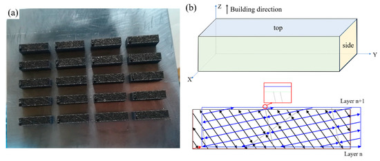
Figure 1.
Images of (a) selective laser melting (SLM) processed bending samples and (b) the scanning strategy used for SLM.
2.3. Microstructure Characterization
The printed samples are separated from the base plate by a line cutting machine, followed by ultrasonic cleaning for 1 h to remove pollutants such as oil stains, to guarantee the accuracy for measurement. The relative density of the samples is obtained by a densimeter (FA2004J, Shanghai Yueping Scientific Instrument Co., Ltd., Shanghai, China) based on the Archimedean principle. The relative density of 10 samples is measured, and an arithmetic average is calculated. The roughness of the samples (top and side surfaces) is measured by a microscope (VK-X1100, KEYENCE, Osaka, Japan). An optical microscope (OM, 5XB-PC, Shanghai Optical Instrument Factory No. 1, Shanghai, China) is applied to analyze the defects after the samples being milled and polished by SiC sandpapers. The samples are etched with a Keller (nitric acid 2.5 mL, hydrochloric acid 1.5 mL, hydrofluoric acid 1.5 mL, distilled water 95 mL) for about 2 min and then used for metallographic examination. The microstructure is observed by a scanning electron microscope (SEM, SU1510, HITACHI, Japan). X-ray diffraction (XRD, DX-2700, Dandongfangyuan Instrument Co., Ltd., Dandong, China) is performed at room temperature using a Cu-tube at 30 kV and 30 mA. The X-ray generator with Cu Kα1 (λ = 0.15406 nm) radiation is applied, with the scan rate of 6°/min and the 2θ angle varying from 20° to 90°.
2.4. Mechanical Properties Characterization
A bending test is implemented to obtain the mechanical strength of Al-Si alloys processed by SLM because of the brittle feature of SLMed hypereutectic Al-Si alloys [45]. The bending strength and microhardness of printed samples are tested at room temperature using a hydraulic universal testing machine (CHT4305, MTS, Eden Prairie, MI, USA) and Vickers hardness machine (DHV-100, Shanghai Shangcai Testermaching Co., Ltd., Shanghai, China). The three-point bending method is applied for the measurement of bending strength. The distance of support cylinders on the fixtures is 16 mm, and the loading rate is set to be 0.5 mm/min. A total of 6 samples are tested for bending strength, and the average is calculated. The loading duration of the microhardness test is set to be 15 s with a load of 1.96 N. The microhardness of 2 samples (including top and side surfaces) are measured. Three points are tested on each surface of the samples.
3. Results and Discussion
3.1. Powder Characterization
The chemical composition of the Al alloy studied in this work is shown in Table 2 and Table 3. The raw material mainly consists of Al and Si with little Fe, Cu, Re, and other elements. The true density of this powder (see Table 2) is 2.6486 g/cm3. The particle size distribution is d10 = 16.39 μm, d50 = 25.39 μm, d90 = 49.78 μm. Figure 2a presents how the volume and number fraction of the powder varies with particle size. Two peaks are observed at both curves near the same particle size but with different peak heights. When the particle size of the powder is in the range of 10 to 20 μm, the large amounts of particles in this range leads to a slight increase of powder volume.
Table 3.
Weight percent composition of Re (mixed rare earth metals).
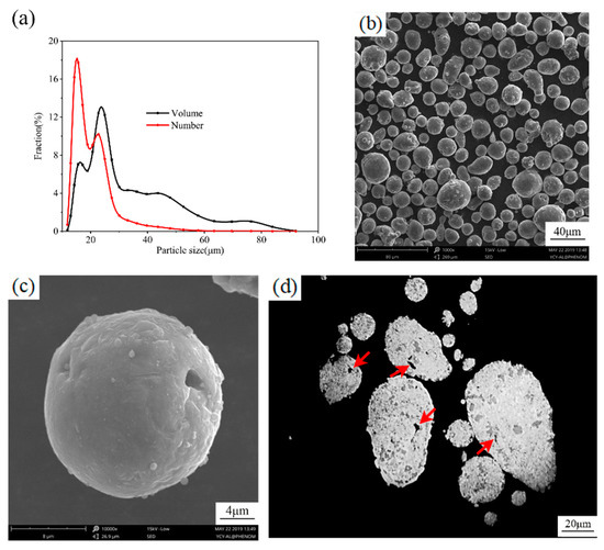
Figure 2.
(a) Particle size distribution and (b,c) morphologies of fresh feedstock powder and (d) its cross-section image with red arrows referring to irregular internal pores.
Powder quantity is significantly reduced with particle size greater than 40 μm, whereas the volume fraction is still high. It indicates the existence of a few particles with large size, which have a negative impact on the process of SLM since large particles are favored neither for energy efficiency nor for flowability. SEM investigations of the powder material demonstrate that the particles have a nearly spherical shape and smooth surface with almost no attached satellites. These characteristics lead to better flowability for powders, and additionally, the deposition of a uniform layer for the SLM process is ensured [31,46]. A few holes induced by gas escaping from droplets during the atomization process are found on the surface of the powder particles (Figure 2c). A polished cross-section of powder particles (Figure 2d) reveals their internal morphology. Irregularly shaped pores (pointed out by red arrows) with a size around 3 μm are found, which implies the presence of entrapped gas that gives rise to porosity [13,31] in the as-built samples. Small spherical primary silicon grains (the gray area) [46,47] that are evenly dispersed inside particles can be observed. The homogeneous powder contributes to a reduction of segregation that might occur in the as-SLMed samples.
The Al-22Si-0.2Fe-0.1Cu-Re powder has a suitable particle shape, proper surface state, and uniform composition which are favored for the SLM process [13], yet appropriate process parameters should still be applied to eliminate the influence of defects caused by imperfect particle size distribution and internal pores [31].
3.2. Phase Analysis and Forming Quality
3.2.1. Phase Analysis
The Al-Si binary phase diagram, together with the XRD patterns of the Al-Si powder and those of the top and side surface of the SLMed samples, are shown in Figure 3. According to the Al-Si binary phase diagram, hypereutectic Al-Si alloy consists of primary silicon phase and α-aluminum phase, which leads to its unique structures and properties. XRD patterns in Figure 3b also suggest the presence of α-Al and Si in both the powder particles and the as-built specimens and no new phase and oxide are detected. Compared to powder materials, the α-Al peaks of both top and side surfaces of the as-built samples shift to higher angles, which reveals the existence of lattice distortion induced by large residual stresses associated with the high heating and cooling rate [33] characteristic of the SLM process and the increase of solid solubility of Si in α-Al. This result is confirmed by Ma et al. [40] in SLMed Al-20Si alloys and also reported for SLMed Al-50Si [7,11] and Al-12Si (wt.%) [25] alloys. The weak intensity of the Si peaks that indicates the decrease of “free” silicon also validates this result.
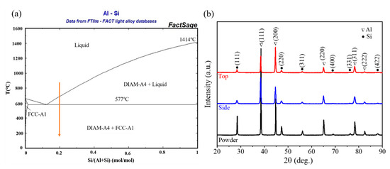
Figure 3.
(a) Al-Si binary phase diagram and (b) XRD patterns of the Al-Si powder and the top and side surface of the SLMed samples.
The specific solubility of Si in the Al matrix can be estimated by a linear relationship of Vegard’s Law [11,30,40,48]:
where a is the lattice parameter of α-Al and is the atomic fraction of Si.
On the basis of a measured by the XRD patterns, is calculated to be 8.25%, which is higher than the maximum solubility of Si at eutectic (1.65%) and room (0.05%) temperature [40]. The change of solid solubility of Si is more obvious compared with samples processed by casting [11,25,40], which is the conventional manufacturing techniques of hypereutectic Al-Si alloys.
It can be observed that the Si peaks of the as-built specimen for both surfaces are wider than that of the powder particles, indicating a reduced size of primary silicon [25]. The intensity of Al (111) and Al (200) peaks of the side surface of the as-built sample is reversed with respect to the top surface of the same sample. This phenomenon illustrates the existence of texture in different tested samples. The texture of the bulk samples has been reported by Jia et al. [11].
3.2.2. Densification and Porosity
Almost dense samples whose relative density is 99.54 ± 0.25% are built in this work. Porosity defects can be found on the surface and interior of the as-built specimens, as shown in Figure 4, which results in the decrease of relative density. Typical molten pool morphology of SLMed samples is also visible in the optical microscopic images. The molten pools with diverse sizes and a half-cylindrical shape are shown in Figure 4b,d. Metallurgical pores and lack-of-fusion pores [3,13,31,34] are common defects formed in the SLMed materials. The metallurgical pores characterized as small size and spherical morphology [34] evenly distribute inside the sample, while the lack-of-fusion pores with large size and irregular shape [3] are mainly found beside the molten pool boundaries. By using optimized processing parameters, no keyhole pores or large lack-of-fusion pores which are significantly detrimental to the mechanical properties of the as-built samples are found in this study. The influence of a few lack-of fusion pores and small metallurgical pores that can hardly be removed on the bending performance can be minimal [3]. In addition, more pores are observed on the surface (Figure 4a) than inside (Figure 4c), which is attributed to thermal influence (i.e., remelting [49]) caused by subsequent laser scanning to some extent. This phenomenon could lead to the enhancement of the sample densification. Our findings are also confirmed by Dai et al. [49], who reported that the entrapped gas in the solidified molten pool may shift upward and escape during the remelting of the previous layer.
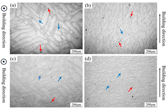
Figure 4.
Typical pores of as-built specimens: pores on the (a) top and (b) side surface of the bulk specimen and internal pores of (c) top and (d) side surface of the bulk specimen. (Metallurgical pores and lack-of-fusion pores are pointed out by blue arrows and red arrows, respectively).
3.2.3. Surface Roughness
Figure 5 illustrates the surface quality of the top and side surface of the as-built specimen with the roughness of 10.407 μm and 14.578 μm, respectively. Apparent laser scanning traces are found and depicted in Figure 5a. The roughness of the top surface can be divided into two parts: one is smoother but contains some holes on it, another is rougher with obvious protrusions breaking the regular scanning traces. This phenomenon is attributed to the strip scan strategy, which divides a large scanning surface into several smaller parts. Areas around the junction of two parts are rougher due to the unstable state of the molten pool at the start and end of scan tracks [41,50] and the residual stress in different parts [33]. The side surface is covered by powder particles during the entire SLM process, so balling and satellites illustrated as protrusions in Figure 5b are quite common surface defects in SLMed specimens. It is worthy to note that the presence of apparent boundaries between layer and layer worsens the surface roughness. The top surface of the specimen exhibits better surface quality compared to the side surface or other SLMed samples [33]. The side surface defects have more negative effects on the bending strength, which will be discussed later.
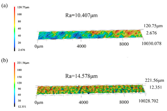
Figure 5.
The surface quality of the (a) top and (b) side face of the as-built specimen.
3.3. Microstructure Characterization
The microstructure of the top and side surface of the etched sample is depicted in Figure 6 and Figure 7. The molten pool morphology (white molten pool boundaries and gray cores shown in Figure 6a and Figure 7a) can be clearly distinguished at lower magnification. A fine but inhomogeneous microstructure with metastable phase generated by the high cooling rate [26,33] can be catalogued into three distinct regions, namely, the fine zone, the coarse zone, and the heat-affected zone (HAZ) [21,26,41]. The fine zone at the molten pool core (Figure 6c and Figure 7c) shows characteristic petaloid structures [40,51] composed of fine near-spherical primary silicon in the center, elongated fibrous silicon network around the primary silicon, fine fibrous silicon around the silicon network, and bulk Al-Si eutectic structures with ultrafine fibrous silicon, divided into different grains by grain boundaries (marked by a red dash line in Figure 6c and Figure 7c). The petaloid structures are destroyed with a fibrous silicon network broken into particles, and bulk Al-Si eutectic structures do not exist in the HAZs (Figure 6d and Figure 7d), which only consists of coarse silicon particles and primary silicon. In the coarse zone at the bottom of the molten pool (marking with yellow dash line in Figure 6b and Figure 7b), coarser primary silicon, smaller bulk Al-Si eutectic, coarser cellular-dendrites coexist, and the petaloid structures partially remain. Due to the rapid solidification rate of the SLM process, the primary silicon is evenly distributed among three regions with average sizes of ~0.5 μm, ~0.7 μm, and ~1 μm, respectively, which is significantly smaller than that (size of 60–80 μm) in the as-cast samples [40]. The microstructures of the Al-22Si-0.2Fe-0.1Cu-Re samples are remarkably different with other [11,21,26,41,46,51] SLMed Al-Si alloys with different silicon content. There is no appreciable difference between the morphology of the top and the side surface of the same sample. All of these phenomena are considered to be attributed to the formation of primary Si located in the center of unique petaloid structures. The morphology of primary Si is consistent in both surfaces, and the subsequent phases remain constant as a result, which suggests the morphology of the primary phase plays a pivotal role in the final structures [51].
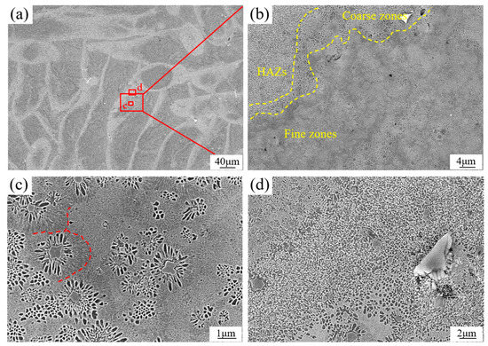
Figure 6.
The microstructure of the as-built Al-Si samples in top view. The molten pool morphology of the top surface of a sample etched with Keller’s are visible in the SEM image (a). The structure in the red frame in the picture (a) is magnified to ensure visibility in the picture (b–d). In picture (b), fine zones and coarse zones are distinguished by yellow dash lines as well as the heat-affected zones (HAZs). The morphologies of fine zones and HAZs are illustrated at higher magnifications in the picture (c,d).
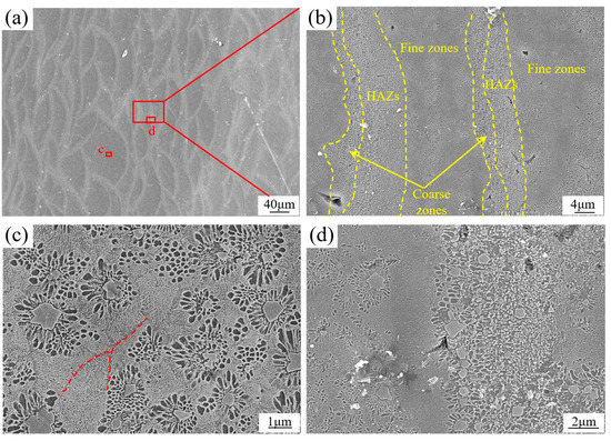
Figure 7.
The microstructure of the as-built Al-Si samples in side view. The scan tracks (white zones) morphology of the top surface of the sample etched with Keller’s are visible in the SEM image (a). The structure in the red frame in the picture (a) is magnified to ensure visibility in the picture (b–d). In picture (b), fine zones and coarse zones are distinguished by yellow dash lines as well as the HAZs. The morphologies of fine zones and HAZs are illustrated at higher magnifications in the picture (c,d).
The solidification mechanism in SLMed Al-22Si-0.2Fe-0.1Cu-Re alloy is believed to be cellular-dendritic and eutectic [13]. Due to the liquid oscillations and temperature profile, an inhomogeneous structure is formed in the molten pools [28]. According to the Al-Si binary phase diagram, Si phase nucleates firstly in the Si-rich area, which is regarded as the heterogeneous nucleation mechanism with the detailed process being that the grains remain from the partially molten zone or laser spatters land onto the molten pool as the possible nucleation center [13]. The solidification front rejects Al into the liquid with the growth of Si particles. As a result, the solvent Al is enriched in the undercooled liquid surrounding the Si particle, then the α-Al phase solidifies as a cellular structure in the Al-rich area with residual Si segregated at the cellular boundaries around the Si phase, which exactly hinders the growth of the primary Si phase [40]. Subsequently, the component of the liquid is transferred into the eutectic zone. The eutectic phase is solidified both around the already generated phase and in the liquid phase, where equiaxed grains are eventually formed, separated by grain boundaries. Moreover, ultrafine fibrous eutectic Si is formed on the matrix because of the rapid cooling rate and high thermal gradients (as high as 103~108 K/s [28]).
For the formation of coarse zones and HAZs, the reason is related to the heat effect of the next hatch or layer, which causes the partial remelting of the hatches or layers that are previously-deposited during the SLM process [21,22,41]. The schematic diagram is shown in Figure 8. The temperature reaches its maximum value at the laser contact point and gradually decreases as the distance gets farther. When the temperature is between solidus and liquidus, already-solidified metal is remelted in a semi-solid state [21]. According to the Al-Si binary phase diagram, some primary silicon that remains solid because of a high melting point will grow at this temperature range, causing the reduction of Si, which further results in coarser α-Al phase and reduced eutectic phase. Hence, the coarse zones are formed, whereas the structures are still fine because of the high cooling rate [28]. Beside the coarse zones where the temperature is lower than solidus, the base metal is still solid but undergoes heat effects just like heat treatments [21,30,40]. Therefore, the Si network is broken into particles, and Si precipitates generated from the supersaturated Al and eutectic Si become coarser owing to the increased Si diffusion, which is induced by the heat source [30,41], and thus, the HAZs are formed under this condition. Nevertheless, the “heat treatment” process only lasts for a very short time because of the high movement rate of the heat source and high heat dissipation effect, which corresponds to the limited time for Si particles to grow. As a result, a fine structure is formed in the HAZs with an even dispersion of Si particles and primary Si. Similar results with respect to formation of coarse zones and HAZs are also reported by others [21,25,30,41].
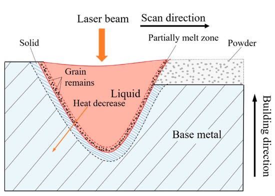
Figure 8.
Schematic of the formation of the microstructure with three zones of the as-built samples.
3.4. Mechanical Properties
3.4.1. Micro-Hardness
To investigate the mechanical properties of the as-built specimens, Vickers hardness is tested. The average micro-hardness of the top, side, and front surface is 176.85 ± 10.25 HV0.2, 173.27 ± 4.93 HV0.2, and 171.37 ± 11.17 HV0.2, respectively. It is worth noting that the Vickers micro-hardness values of three surfaces are almost the same, demonstrating the uniformity of micro-hardness for the whole specimen. Besides, the SLMed Al-Si alloys that we prepare show an excellent micro-hardness value higher than or almost the same as the as-cast and other SLMed Al-Si alloys as shown in Table 4, which could be mainly ascribed to the fine microstructure and high Si content of the alloy [13].
Table 4.
Microhardness of the Al-Si alloys manufactured by cast, SLM, and SLM with heat treatment.
3.4.2. Bending Properties
The as-SLMed Al-Si alloys usually show brittle and low ductility features [13,25,30,33]. It has been reported that the number of defects is correlated to sample size [58]. For further investigations on the mechanical properties of as-built samples, a bending test is conducted whose samples could be small and simple in shape. What is more, density, defects, and other performance analyses could also be conducted using these samples without the deviation caused by sample size. The dimension of the bending sample is depicted in Figure 9a. The bending strength-displacement curves of as-fabricated Al-22Si-0.2Fe-0.1Cu-Re specimens tested at room temperature are shown in Figure 9b. These specimens have excellent bending strength that is measured to be 644.0 ± 43.7 MPa, which is much higher than the conventional counterparts and almost the same as SLMed AlSi10Mg alloys and SLMed TiB2/AlSi10Mg composite as shown in Table 5. Nevertheless, the bending strength of different specimens processed by the same SLM parameters has relatively large fluctuations, which may be attributed to the unstable distribution of defects [13].
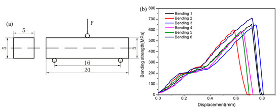
Figure 9.
(a) Dimension of the as-SLMed Al-Si samples and (b) bending strength-displacement curves for the as-built samples.
Table 5.
Bending data for the Al-Si alloys manufactured by different methods.
Figure 10 shows the fracture morphologies of the bending samples. The fracture is relatively flat with no significant deformation being observed. It is obvious that the crack initiates near the side surface of the net-shaped sample (shown in Figure 10a) and propagates inward, leading to fracture. Notch defects (marked by the white arrow in Figure 10b) between layers are regarded to be responsible for the crack initiation, implying that surface defects have a detrimental influence on the bending property of the SLMed parts [3]. Inclusions (marked by red arrows) can also be observed in the crack initiation site.
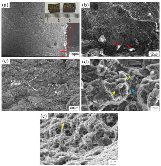
Figure 10.
Bending fraction morphologies of the as-built Al-Si alloys. (a) Overall view of the fracture sample and its crack initiation region (marked by red frame) is magnified in picture (b), with inclusions and notch defects pointed out by red and white arrows, respectively. (c) Partially magnified image of the fracture surface. Two different fracture morphologies are illustrated at higher magnifications in the picture (d,e), with fractured and debonding Si particles marked by yellow and blue arrows, respectively.
In Figure 10c, cleavage steps and cavities can be found on the fracture surface. The presence of cleavage planes further confirms the occurrence of brittle fracture and low plasticity of the as-built samples [30,33,65]. Two main morphologies resembling the microstructure shown in Figure 6 and Figure 7 are revealed in Figure 10d,e, respectively, corresponding to the fracture morphology of cores and boundaries of the molten pools [25,30]. In Figure 10d, obvious microcracks exist in bulk Si particles (marked by yellow arrows in Figure 10d), which are generated from the large residual stress around hard and brittle Si particles during bending. Fractured Si particles will become the preferential sites for the crack initiation site and further result in fracture of the samples. On the other hand, cracks also initiate from a small part of Si particles that are expected to be separated from the matrix as indicated by the smooth surface marked by the blue arrow in Figure 10d. Therefore, the fracture or decohesion of Si particles could be responsible for crack initiation and propagation [3,60]. The shallow dimples, which are the characteristic of a ductile fracture, are observed in the molten pool boundary in Figure 10e, which implies a better ductility of this zone. In addition, fractured Si particles could often be found at the end of the dimples, as highlighted by yellow arrows in Figure 10e.
The enhancement of the strength of the as-fabricated parts processed by SLM could be attributed to possible reasons as follows:
- (i)
- Due to the rapid cooling rate of the SLM process, the solubility of Si in the Al matrix has a significant increase, which leads to the lattice distortion [33] and further hinders dislocation movement [18]. Hence, the strength and hardness of the as-built samples are improved by solid-solution strengthening.
- (ii)
- The primary Si particles formed in conventional cast hypereutectic Al-Si alloys have coarse polygonal morphology (with the average size of ~80 μm) and are unevenly distributed in the matrix [40], which could easily accumulate strain during bending or tensile tests, causing fracture or decohesion of Si particles [3,60], then seriously deteriorating the mechanical properties of hypereutectic Al-Si alloys [61,64]. A lot of research has been done to improve the mechanical properties of hypereutectic Al-Si alloys through adjusting the morphology, size, and distribution of primary Si particles [48,56,64]. Due to the high cooling rate, primary silicon in the as-built samples has extremely small sizes (about 1 μm), nearly spherical morphology, and uniform distribution. Therefore, the stress accumulation around these primary Si particles is rather small compared to that around those particles in conventional cast alloys, which is beneficial to the performance improvement of Al-22Si-0.2Fe-0.1Cu-Re alloys. In addition, the presence of a highly-dispersed nanosized eutectic Si phase in the matrix could also hinder dislocation movement, according to the Orowan strengthening mechanism [18].
- (iii)
- Moreover, grain refinement is also expected to be responsible for the improved properties [25,57]. With the decrease of crystallite size, the number of grains begins to rise, along with the increase of grain boundaries that is considered to be the resistance for dislocation movement, and thus, it is harder for the dislocation to move among grains, leading to a significant enhancement for strength.
- (iv)
- The final reason is that the unique molten pool morphology is formed in the whole SLMed parts [49]. Significantly different structures between the molten pool cores and boundaries can be observed, which induces visible differences in the bending fracture morphologies. Hence, the molten pool boundary acting as the grain boundary considerably restricts the propagation of cracks, resulting in the enhanced mechanism of the as-built samples. Moreover, the size, amount, and shape of the molten pool can be modified by optimizing processing parameters [49], implying the possibility of further enhanced properties.
4. Conclusions
In this work, the almost dense Al-22Si-0.2Fe-0.1Cu-Re alloy parts are fabricated using optimized processing parameters and a novel type of powder materials. The powder properties together with the phase, defects, microstructures, and mechanical properties of the as-built parts are systematically studied. The main conclusions can be drawn as follows.
- (1)
- Due to the rapid cooling rate of the SLM process, the solid solubility of Si in the Al matrix has an obvious increase estimated to be 8.25%, which is beneficial to the enhancement of the bending strength and hardness of the SLMed Al-Si alloys.
- (2)
- The relative density of the Al-22Si-0.2Fe-0.1Cu-Re alloys samples reaches 99.54 ± 0.25%. Porosity and surface defects can still be observed for the almost dense specimens. More pores exist near the surface than inside, leading to the enhancement of the sample densification, which could be attributed to remelting of the solidified layers. The surface quality of the top face of the specimen is better than that of the side face, and the side surface defects have an obvious detrimental effect on the bending strength of as-built samples.
- (3)
- There is no appreciable difference between the fine microstructures of the top and side surface of the sample. Three zones can be observed from the microstructure. (i) Fine zones with characteristic petaloid structures and bulk Al-Si eutectic are formed directly from the liquid formed by melted powder and remelted base metal and solidified as cellular-dendritic and eutectic. (ii) Because of the thermal effect induced by laser scanning of the next hatch or layer, coarse zones with grown-up primary Si and partially broken petaloid structures and Al-Si eutectic generate from remelted base metal in a semi-solid state close to fine zones. (iii) The temperature decreases as it is away from the laser contact point, so the base metal remains solid while undergoing heat effects just like heat treatments. As a result, the HAZs with Si particles and primary Si generate beside the coarse zones.
- (4)
- The mechanical properties of Al-22Si-0.2Fe-0.1Cu-Re alloy parts processed by SLM are significantly improved. Due to the fine microstructure induced by a high cooling rate, Vickers hardness reaches ~170 HV0.2, and bending strength increases to 644.0 ± 43.7 MPa for the as-built samples. The micro-hardness is uniform for the bulk sample with similar Vickers hardness. The enhanced bending strength could be attributed to solid-solution strengthening, the optimization of Si phase, grain refinement, and the formation of unique molten pool morphology in the SLM process.
Author Contributions
Conceptualization, B.Y., P.Y., and C.Y.; methodology, C.Y., X.W., and P.Y.; validation, C.Y., Z.L., and P.Y.; formal analysis, C.Y. and X.W.; investigation, C.Y.; resources, P.Y. and B.Y.; writing—original draft preparation, C.Y. and Z.L.; writing—review and editing, C.Y., X.W., Z.L., and P.Y.; visualization, C.Y. and Z.L.; supervision, P.Y. and X.W.; project administration, P.Y., C.Y., and B.Y.; funding acquisition, B.Y. All authors have read and agreed to the published version of the manuscript.
Funding
This research received no external funding.
Data Availability Statement
The data presented in this study are available on request from the corresponding author.
Conflicts of Interest
The authors declare no conflict of interest.
References
- Kang, N.; El Mansori, M. A new insight on induced-tribological behaviour of hypereutectic Al-Si alloys manufactured by selective laser melting. Tribol. Int. 2019. [Google Scholar] [CrossRef]
- Goudar, D.M.; Raju, K.; Srivastava, V.C.; Rudrakshi, G.B. Effect of copper and iron on the wear properties of spray formed Al–28Si alloy. Mater. Des. 2013, 51, 383–390. [Google Scholar] [CrossRef]
- Rao, J.H.; Zhang, Y.; Huang, A.; Wu, X.; Zhang, K. Improving fatigue performances of selective laser melted A1-7Si-0.6Mg alloy via defects control. Int. J. Fatigue 2019, 129. [Google Scholar] [CrossRef]
- Kang, N.; Coddet, P.; Chen, C.; Wang, Y.; Liao, H.; Coddet, C. Microstructure and wear behavior of in-situ hypereutectic Al–high Si alloys produced by selective laser melting. Mater. Des. 2016, 99, 120–126. [Google Scholar] [CrossRef]
- Jiao, X.Y.; Wang, J.; Liu, C.F.; Guo, Z.P.; Tong, G.D.; Ma, S.L.; Bi, Y.; Zhang, Y.F.; Xiong, S.M. Characterization of high-pressure die-cast hypereutectic Al-Si alloys based on microstructural distribution and fracture morphology. J. Mater. Sci. Technol. 2019, 35, 1099–1107. [Google Scholar] [CrossRef]
- Jia, Y.; Cao, F.; Scudino, S.; Ma, P.; Li, H.; Yu, L.; Eckert, J.; Sun, J. Microstructure and thermal expansion behavior of spray-deposited Al–50Si. Mater. Des. 2014, 57, 585–591. [Google Scholar] [CrossRef]
- Kang, N.; Coddet, P.; Ammar, M.-R.; Liao, H.; Coddet, C. Characterization of the microstructure of a selective laser melting processed Al-50Si alloy: Effect of heat treatments. Mater. Charact. 2017, 130, 243–249. [Google Scholar] [CrossRef]
- Hogg, S.C.; Lambourne, A.; Ogilvy, A.; Grant, P.S. Microstructural characterisation of spray formed Si–30Al for thermal management applications. Scr. Mater. 2006, 55, 111–114. [Google Scholar] [CrossRef]
- Haghayeghi, R.; Zoqui, E.J.; Timelli, G. Enhanced refinement and modification via self-inoculation of Si phase in a hypereutectic aluminium alloy. J. Mater. Process. Technol. 2018, 252, 294–303. [Google Scholar] [CrossRef]
- Gao, B.; Hu, L.; Li, S.-W.; Hao, Y.; Zhang, Y.-D.; Tu, G.-F.; Grosdidier, T. Study on the nanostructure formation mechanism of hypereutectic Al–17.5Si alloy induced by high current pulsed electron beam. Appl. Surf. Sci. 2015, 346, 147–157. [Google Scholar] [CrossRef]
- Jia, Y.D.; Ma, P.; Prashanth, K.G.; Wang, G.; Yi, J.; Scudino, S.; Cao, F.Y.; Sun, J.F.; Eckert, J. Microstructure and thermal expansion behavior of Al-50Si synthesized by selective laser melting. J. Alloys Compd. 2017, 699, 548–553. [Google Scholar] [CrossRef]
- Olakanmi, E.O.; Cochrane, R.F.; Dalgarno, K.W. A review on selective laser sintering/melting (SLS/SLM) of aluminium alloy powders: Processing, microstructure, and properties. Prog. Mater. Sci. 2015, 74, 401–477. [Google Scholar] [CrossRef]
- Aboulkhair, N.T.; Simonelli, M.; Parry, L.; Ashcroft, I.; Tuck, C.; Hague, R. 3D printing of Aluminium alloys: Additive Manufacturing of Aluminium alloys using selective laser melting. Prog. Mater. Sci. 2019, 106, 100578. [Google Scholar] [CrossRef]
- Frazier, W.E. Metal Additive Manufacturing: A Review. J. Mater. Eng. Perform. 2014, 23, 1917–1928. [Google Scholar] [CrossRef]
- Li, Y.; Gu, D. Parametric analysis of thermal behavior during selective laser melting additive manufacturing of aluminum alloy powder. Mater. Des. 2014, 63, 856–867. [Google Scholar] [CrossRef]
- Gu, D.; Hagedorn, Y.-C.; Meiners, W.; Meng, G.; Batista, R.J.S.; Wissenbach, K.; Poprawe, R. Densification behavior, microstructure evolution, and wear performance of selective laser melting processed commercially pure titanium. Acta Mater. 2012, 60, 3849–3860. [Google Scholar] [CrossRef]
- Kang, N.; Coddet, P.; Liao, H.; Baur, T.; Coddet, C. Wear behavior and microstructure of hypereutectic Al-Si alloys prepared by selective laser melting. Appl. Surf. Sci. 2016, 378, 142–149. [Google Scholar] [CrossRef]
- Liu, Y.; Wang, R.; Peng, C.; Cai, Z.; Zhou, Z.; Li, X.; Cao, X. Microstructural evolution and mechanical performance of in-situ TiB2/AlSi10Mg composite manufactured by selective laser melting. J. Alloys Compd. 2021, 853, 157287. [Google Scholar] [CrossRef]
- Rakesh, C.H.S.; Priyanka, N.; Jayaganthan, R.; Vasa, N.J. Effect of build atmosphere on the mechanical properties of AlSi10Mg produced by selective laser melting. Mater. Today Proc. 2018, 5, 17231–17238. [Google Scholar] [CrossRef]
- Guang, F. Microstructure and Tensile Properties of AlSi10Mg Alloy Manufactured by Multi-Laser Beam Selective Laser Melting (SLM). Metals 2020, 9, 1337. [Google Scholar]
- Liu, X.; Zhao, C.; Zhou, X.; Shen, Z.; Liu, W. Microstructure of selective laser melted AlSi10Mg alloy. Mater. Des. 2019, 168. [Google Scholar] [CrossRef]
- Wei, P.; Wei, Z.; Chen, Z.; Du, J.; He, Y.; Li, J.; Zhou, Y. The AlSi10Mg samples produced by selective laser melting: Single track, densification, microstructure and mechanical behavior. Appl. Surf. Sci. 2017, 408, 38–50. [Google Scholar] [CrossRef]
- Aboulkhair, N.T.; Maskery, I.; Tuck, C.; Ashcroft, I.; Everitt, N.M. The microstructure and mechanical properties of selectively laser melted AlSi10Mg: The effect of a conventional T6-like heat treatment. Mater. Sci. Eng. A 2016, 667, 139–146. [Google Scholar] [CrossRef]
- Wang, L.F.; Sun, J.; Yu, X.L.; Shi, Y.; Zhu, X.G.; Cheng, L.Y.; Liang, H.H.; Yan, B.; Guo, L.J. Enhancement in mechanical properties of selectively laser-melted AlSi10Mg aluminum alloys by T6-like heat treatment. Mater. Sci. Eng. A 2018, 734, 299–310. [Google Scholar] [CrossRef]
- Prashanth, K.G.; Scudino, S.; Klauss, H.J.; Surreddi, K.B.; Loeber, L.; Wang, Z.; Chaubey, A.K.; Kuehn, U.; Eckert, J. Microstructure and mechanical properties of Al-12Si produced by selective laser melting: Effect of heat treatment. Mater. Sci. Eng. A 2014, 590, 153–160. [Google Scholar] [CrossRef]
- Rao, J.H.; Zhang, Y.; Zhang, K.; Wu, X.; Huang, A. Selective laser melted Al-7Si-0.6Mg alloy with in-situ precipitation via platform heating for residual strain removal. Mater. Des. 2019, 182. [Google Scholar] [CrossRef]
- Suryawanshi, J.; Prashanth, K.G.; Scudino, S.; Eckert, J.; Prakash, O.; Ramamurty, U. Simultaneous enhancements of strength and toughness in an Al-12Si alloy synthesized using selective laser melting. Acta Mater. 2016, 115, 285–294. [Google Scholar] [CrossRef]
- Li, X.P.; Wang, X.J.; Saunders, M.; Suvorova, A.; Zhang, L.C.; Liu, Y.J.; Fang, M.H.; Huang, Z.H.; Sercombe, T.B. A selective laser melting and solution heat treatment refined Al-12Si alloy with a controllable ultrafine eutectic microstructure and 25% tensile ductility. Acta Mater. 2015, 95, 74–82. [Google Scholar] [CrossRef]
- Ponnusamy, P.; Masood, S.H.; Ruan, D.; Palanisamy, S.; Rashid, R. High strain rate dynamic behaviour of AlSi12 alloy processed by selective laser melting. Int. J. Adv. Manuf. Technol. 2018, 97, 1023–1035. [Google Scholar] [CrossRef]
- Li, W.; Li, S.; Liu, J.; Zhang, A.; Zhou, Y.; Wei, Q.; Yan, C.; Shi, Y. Effect of heat treatment on AlSi10Mg alloy fabricated by selective laser melting: Microstructure evolution, mechanical properties and fracture mechanism. Mater. Sci. Eng. A 2016, 663, 116–125. [Google Scholar] [CrossRef]
- Aboulkhair, N.T.; Everitt, N.M.; Ashcroft, I.; Tuck, C. Reducing porosity in AlSi10Mg parts processed by selective laser melting. Addit. Manuf. 2014, 1–4, 77–86. [Google Scholar] [CrossRef]
- Mower, T.M.; Long, M.J. Mechanical behavior of additive manufactured, powder-bed laser-fused materials. Mater. Sci. Eng. A 2016, 651, 198–213. [Google Scholar] [CrossRef]
- Bi, J.; Lei, Z.; Chen, Y.; Chen, X.; Tian, Z.; Liang, J.; Qin, X.; Zhang, X. Densification, microstructure and mechanical properties of an Al-14.1Mg-0.47Si-0.31Sc-0.17Zr alloy printed by selective laser melting. Mater. Sci. Eng. A 2020, 774. [Google Scholar] [CrossRef]
- Yang, K.V.; Rometsch, P.; Jarvis, T.; Rao, J.; Cao, S.; Davies, C.; Wu, X. Porosity formation mechanisms and fatigue response in Al-Si-Mg alloys made by selective laser melting. Mater. Sci. Eng. A 2018, 712, 166–174. [Google Scholar] [CrossRef]
- Fousova, M.; Dvorsky, D.; Vronka, M.; Vojtech, D.; Lejcek, P. The Use of Selective Laser Melting to Increase the Performance of AlSi9Cu3Fe Alloy. Materials 2018, 11, 1918. [Google Scholar] [CrossRef] [PubMed]
- Pozdniakov, A.V.; Churyumov, A.Y.; Loginova, I.S.; Daubarayte, D.K.; Ryabov, D.K.; Korolev, V.A. Microstructure and properties of novel AlSi11CuMn alloy manufactured by selective laser melting. Mater. Lett. 2018, 225, 33–36. [Google Scholar] [CrossRef]
- Sistiaga, M.L.M.; Mertens, R.; Vrancken, B.; Wang, X.; Van Hooreweder, B.; Kruth, J.-P.; Van Humbeeck, J. Changing the alloy composition of A17075 for better processability by selective laser melting. J. Mater. Process. Technol. 2016, 238, 437–445. [Google Scholar] [CrossRef]
- Casati, R.; Coduri, M.; Riccio, M.; Rizzi, A.; Vedani, M. Development of a high strength Al-Zn-Si-Mg-Cu alloy for selective laser melting. J. Alloys Compd. 2019, 801, 243–253. [Google Scholar] [CrossRef]
- Ma, C.; Wei, X.; Yan, B.; Yan, P. Numerical Simulation of Moving Heat Flux during Selective Laser Melting of AlSi(25)Alloy Powder. Metals 2020, 10, 877. [Google Scholar] [CrossRef]
- Ma, P.; Scudino, S.; Jia, Y.; Wang, H.; Zou, C.; Wei, Z.; Eckert, J. Influence of Annealing on Mechanical Properties of Al-20Si Processed by Selective Laser Melting. Metals 2014, 4, 28–36. [Google Scholar] [CrossRef]
- Thijs, L.; Kempen, K.; Kruth, J.-P.; Van Humbeeck, J. Fine-structured aluminium products with controllable texture by selective laser melting of pre-alloyed AlSi10Mg powder. Acta Mater. 2013, 61, 1809–1819. [Google Scholar] [CrossRef]
- Rao, H.; Giet, S.; Yang, K.; Wu, X.; Davies, C.H.J. The influence of processing parameters on aluminium alloy A357 manufactured by Selective Laser Melting. Mater. Des. 2016, 109, 334–346. [Google Scholar] [CrossRef]
- Bonaiti, L.; Concli, F.; Gorla, C.; Rosa, F. Bending fatigue behaviour of 17-4 PH gears produced via selective laser melting. Procedia Struct. Integr. 2019, 24, 764–774. [Google Scholar] [CrossRef]
- Lu, G.; Wang, J.; Liu, Y.; Liu, C. Effect of heating rate during solution treatment on the bendability of Al–Mg–Si alloys. Mater. Sci. Eng. A 2020, 791, 139604. [Google Scholar] [CrossRef]
- Ahmad, R.; Hashim, M.Y. Effect of vortex runner gating system on the mechanical strength of Al-12Si alloy castings. Arch. Metall. Mater. 2011, 56, 991–997. [Google Scholar] [CrossRef]
- Müller, M.; Mirko, R.; Eberle, S.; Brandão, A.; Pambaguian, L.; Reutlinger, A.; Seidel, A.; Lopez, E.; Brueckner, F.; Leyens, C.; et al. Microstructural, mechanical and thermo-physical characterization of hypereutectic AlSi40 fabricated by Selective Laser Melting. J. Laser Appl. 2018, 31, 022321. [Google Scholar] [CrossRef]
- Ullsperger, T.; Matthaeus, G.; Kaden, L.; Engelhardt, H.; Rettenmayr, M.; Risse, S.; Tuennermann, A.; Nolte, S. Selective laser melting of hypereutectic Al-Si40-powder using ultra-short laser pulses. Appl. Phys. A 2017, 123, 1–6. [Google Scholar] [CrossRef]
- Li, Y.; Jiang, T.; Wei, B.; Xu, B.; Xu, G.; Wang, Z. Microcharacterization and mechanical performance of an Al-50Si alloy prepared using the sub-rapid solidification technique. Mater. Lett. 2020, 263. [Google Scholar] [CrossRef]
- Dai, D.; Gu, D.; Zhang, H.; Xiong, J.; Ma, C.; Hong, C.; Poprawe, R. Influence of scan strategy and molten pool configuration on microstructures and tensile properties of selective laser melting additive manufactured aluminum based parts. Opt. Laser Technol. 2018, 99, 91–100. [Google Scholar] [CrossRef]
- Liu, S.; Zhu, J.; Zhu, H.; Yin, J.; Chen, C.; Zeng, X. Effect of the track length and track number on the evolution of the molten pool characteristics of SLMed Al alloy: Numerical and experimental study. Opt. Laser Technol. 2020, 123. [Google Scholar] [CrossRef]
- Kimura, T.; Nakamoto, T.; Mizuno, M.; Araki, H. Effect of silicon content on densification, mechanical and thermal properties of Al-xSi binary alloys fabricated using selective laser melting. Mater. Sci. Eng. A 2017, 682, 593–602. [Google Scholar] [CrossRef]
- Buchbinder, D.; Schleifenbaum, H.; Heidrich, S.; Meiners, W.; Bueltmann, J. High Power Selective Laser Melting (HP SLM) of Aluminum Parts. In Lasers in Manufacturing 2011, Proceedings of the Sixth International Wlt Conference on Lasers in Manufacturing, Munich, Germany, 23–26 May 2011; Schmidt, M., Zaeh, M., Graf, T., Ostendorf, A., Eds.; Elsevier: Amsterdam, The Netherlands, 2011; Volume 12, pp. 271–278, Part A. [Google Scholar]
- Raju, K.; Harsha, A.P.; Ojha, S.N. Evolution of microstructure and its effect on wear and mechanical properties of spray cast Al-12Si alloy. Mater. Sci. Eng. A 2011, 528, 7723–7728. [Google Scholar] [CrossRef]
- Bai, Y.; Yang, Y.; Xiao, Z.; Zhang, M.; Wang, D. Process optimization and mechanical property evolution of AlSiMg0.75 by selective laser melting. Mater. Des. 2018, 140, 257–266. [Google Scholar] [CrossRef]
- Zhou, Y.; Duan, L.; Wen, S.; Wei, Q.; Shi, Y. Enhanced micro-hardness and wear resistance of Al-15Si/TiC fabricated by selective laser melting. Compos. Commun. 2018, 10, 64–67. [Google Scholar] [CrossRef]
- Raju, K.; Harsha, A.P.; Ojha, S.N. Effect of processing techniques on the mechanical and wear properties of Al-20Si alloy. Trans. Indian Inst. Met. 2011, 64, 1–5. [Google Scholar] [CrossRef]
- Zhang, S.; Ma, P.; Jia, Y.; Yu, Z.; Sokkalingam, R.; Shi, X.; Ji, P.; Eckert, J.; Prashanth, K.G. Microstructure and Mechanical Properties of Al-(12-20)Si Bi-Material Fabricated by Selective Laser Melting. Materials 2019, 12, 2126. [Google Scholar] [CrossRef]
- Koutny, D.; Palousek, D.; Pantelejev, L.; Hoeller, C.; Pichler, R.; Tesicky, L.; Kaiser, J. Influence of Scanning Strategies on Processing of Aluminum Alloy EN AW 2618 Using Selective Laser Melting. Materials 2018, 11, 298. [Google Scholar] [CrossRef]
- Kurzawa, A.; Kaczmar, J.W. Bending Strength of EN AC-44200—Al2O3 Composites at Elevated Temperatures. Arch. Foundry Eng. 2017, 17, 103–108. [Google Scholar] [CrossRef]
- Fuliang, Y.; Danqing, Y.I.; Wei, Z. Effect of Powders Oxidizing on Microstructure and Mechanical Properties of High-Silicon Aluminum Alloy Hot-Extrusion Composites. Mater. Mech. Eng. 2008, 32, 57–60. [Google Scholar]
- Yang, W.; Chen, G.; Qiao, J.; Liu, S.; Xiao, R.; Dong, R.; Hussain, M.; Wu, G. Graphene nanoflakes reinforced Al-20Si matrix composites prepared by pressure infiltration method. Mater. Sci. Eng. A 2017, 700, 351–357. [Google Scholar] [CrossRef]
- Liu, J.; Xiu, Z.; Liang, X.; Li, Q.; Hussain, M.; Qiao, J.; Jiang, L. Microstructure and properties of Sip/Al-20 wt% Si composite prepared by hot-pressed sintering technology. J. Mater. Sci. 2014, 49, 1368–1375. [Google Scholar] [CrossRef]
- Cai, Z.; Zhang, C.; Wang, R.; Peng, C.; Wu, X.; Li, H. Microstructure, mechanical and thermo-physical properties of Al-50Si-xMg alloys. Mater. Sci. Eng. A 2018, 730, 57–65. [Google Scholar] [CrossRef]
- Qin, X.; Cheng, H.; Lu, N.; Cheng, F. Effect of P modification on microstructure and properties of Al-50Si composite. Trans. Mater. Heat Treat. 2019, 40, 31–37. [Google Scholar]
- Rao, J.H.; Zhang, Y.; Fang, X.; Chen, Y.; Wu, X.; Davies, C.H.J. The origins for tensile properties of selective laser melted aluminium alloy A357. Addit. Manuf. 2017, 17, 113–122. [Google Scholar] [CrossRef]
Publisher’s Note: MDPI stays neutral with regard to jurisdictional claims in published maps and institutional affiliations. |
© 2021 by the authors. Licensee MDPI, Basel, Switzerland. This article is an open access article distributed under the terms and conditions of the Creative Commons Attribution (CC BY) license (http://creativecommons.org/licenses/by/4.0/).