Article

Effect of Cd2+ on Electrodeposition of Copper in Cyclone Electrodeposition

State Key Laboratory of Complex Nonferrous Metal Resources Clean Utilization, Kunming University of Science and Technology, Kunming 650093, China
*
Author to whom correspondence should be addressed.
Metals 2021, 11(4), 529; https://doi.org/10.3390/met11040529
Submission received: 23 January 2021 / Revised: 11 March 2021 / Accepted: 17 March 2021 / Published: 24 March 2021

Abstract

:
A strategy to determine the effect of Cd2+ on the electrodeposition of copper from a copper electrolyte by cyclone electrowinning is presented. The concentration of Cu2+ in the copper electrolyte with different Cd2+ concentrations was determined by atomic absorption spectrometry (AAS). It indicated that the current efficiency, the rate of electrodeposition, and the rate copper electrodeposition decreased with the addition of Cd2+ in the three stages of electrodeposition. The current efficiency declined from 99.6 to 79.2% and the copper electrodeposition rate declined from 52 to 40% in the first electrodeposition. The current efficiency had no significant change, and the copper electrodeposition rate declined from 88 to 77% in the second electrodeposition. The current efficiency declined from 72.6 to 40.3%, and the copper electrodeposition rate was all at 99% in the third electrodeposition. The influences of the Cd2+ concentration on the purity and morphology of cathode copper were investigated. The effect of Cd2+ concentration on the purity and morphology of cathode copper was also studied. In the three-stage electrodeposition, the addition of the Cd2+ concentration mainly affected the microstructure of the cathode copper, but it had little effect on the purity of the cathode copper. The higher the amount of Cd2+, the rougher the morphology of the cathode copper and the larger the gap between the grains; the higher the amount of Cd2+, the lower the electrodeposition rate and current efficiency, though the reduction was small.

1. Introduction

Copper has excellent thermal conductivity and other metal properties, so it is widely used in electric power, electronics, the construction industry, transportation, industrial machinery manufacturing, consumer goods, and other daily necessities [1,2,3]. With the rapid development of the modern semiconductor industry, the application of ultra-high purity copper has been widely valued [4,5]. Despite the increasing demand for copper, the grade of copper has been declining year by year. Compared with other metals, the recovery of copper is relatively low [6]. Therefore, it is necessary and urgent to study the effective recovery of copper from waste. The key to increase the grade of copper is the separation of metal impurities associated with the copper element [6]. Copper-containing waste is usually treated by a pyrometallurgical process represented by copper smelting [7]. However, due to the complex composition of secondary resources, it is difficult to meet the purity requirements of recycled copper in traditional pyrometallurgy. Therefore, more research has been done on the hydrometallurgy process. In these studies, the principle was mainly to achieve the separation of metal ions by controlling the oxidation–reduction potential in the system and the ion product constant. Many new processes have been developed to treat various types of copper-containing wastes [8,9,10].
Metallic elements such as Zn, Cd, and Fe are often accompanied in copper-containing waste. Among them, Cd is a highly toxic trace element that can enter the human body through the skin, esophagus, respiratory tract, and other channels, thus causing poisoning. Due to its high toxicity, there have been public efforts to reduce or eliminate the use of Cd in many countries [11]. Much research has been done on the removal of Cd by the hydrometallurgical process, e.g., the removal of Cd from sulfate solutions by electrochemical methods [12], the use the nature of organic matter to improve the separation efficiency [13], and the control of arsenic and Cd pollution in the mining process through comprehensive technology [14]. These methods have achieved good separation results, indicating that the electrochemical method has good applicability for the separation of Cd [15].
Cyclone electrodeposition is a relatively new electrodeposition technology [16]. It has obvious technical advantages in the purification and separation of multi-metals [17]. It is widely used in acidic solutions, including sulfuric acid [18], hydrochloric acid [19], nitric acid, and cyanide [17,20] to extract low concentrations of copper [17], cobalt, nickel [21], zinc [19], gold [16], silver [20], and so on [16]. Because of the relatively high-speed motion of the electrolyte and electrode, cyclone electrodeposition avoids the concentration polarization caused by the slow flow of electrolytes in traditional electrodeposition process [17], reduces the thickness of the diffusion layer [5,22,23], and enhances the mass transfer while minimizing ion exchange. This can provide an adequate supply of target metal material at the cathode with minimal thermodynamic or kinetic preference for the deposition of impurity metals [24]. This technology can not only realize the high purity extraction of low concentration metal ions but also realize the collection and recovery of electrolytic mist, which has good economic and environmental benefits. The process of metal recovery by cyclone electrodeposition is widely used in the direct electrodeposition of metals in low-concentration solutions [16]. Many scientists have studied the effects of different experimental conditions on the efficiency of metal recovery in the cyclone electrodeposition process. It has been found that the main working parameters such as working time, pH, and current efficiency all affect the effect of electrodeposition [21,24,25,26,27]. Therefore, the cyclone electrodeposition process can efficiently recover different kinds of metal ions. Since the cyclone electrodeposition process is simple, has a short processing flow, and does not produce acid fog, it can improve working environments, in addition to its many other advantages. Various metal ions in the copper electrolyte can be separated by this process.
However, due to the ion behavior and crystallization process in the cyclone electrodeposition process, it is still unclear how it affects heavy metals, especially cadmium, which is harmful to human body. This could lead to a potential accident when the process is applied to treat raw materials with large composition changes, and because copper resources are increasingly scarce, it is becoming more and more important to study the recovery of copper from secondary resources. Hydrometallurgy produces a large amount of purified copper slag containing a lot of copper resources every year [17,24]. The main method to recover copper is hydrometallurgy, and the method to recover copper efficiently from the solution with a low Cu2+ content is the cyclone electrowinning method. The purification of Cd in copper slag affects the recovery of copper by cyclone electrowinning, but the specific impact and how to affect it have not been elaborated on by scholars, and previous studies have not studied the effect of a single metal ion on the electrodeposition of copper in the swirl electrowinning device. Though the experimental operation is similar to previous studies, the final research direction is inconsistent. This was the innovation of this experiment, so it was necessary to study the thermodynamic behavior of Cd2+ in cyclone electrodeposition to recover copper and the interference or influence mechanism of Cd2+ on crystalline copper.

2. Experimental

In the process of cyclone electrodeposition, the more positive the cathode standard precipitation potential is, the easier it is to precipitate. Because the standard electrode potential of Cu2+ is more positive than that of the Cd2+ standard electrode in the copper electrolyte, copper can be preferentially electrodeposited from the solution, but Cd2+ in the solution will have a certain influence on the copper electrodeposition. The influence of Cd2+ in turbulent electrodeposition technology on the electrodeposition of copper in the copper electrolyte was explored, and experiments were carried out to investigate the influence of Cd2+ on the current efficiency, the removal rate of Cu2+, and the quality and morphology of cathode copper products.

2.1. Reagents and Materials

The experimental materials were mainly used to analyze pure CuSO4 × 5H2O made by Fuchen Chemical Reagent Co., Ltd. in Tianjin China, analyze pure 3CdSO4·× 8H2O made by Xilong Scientific in Guangdong China, 98 wt% H2SO4 made by Xilong Scientific in Guangdong China and the copper electrolyte containing Cd2+ configured with deionized water. The experimental apparatus is shown in Figure 1. The electrolyte composition was 50 g/L of Cu2+ and 2–6 g/L of Cd2+. The main equipment of the experiment were a cyclone electrodeposition device with inert graphene at the anode and titanium plate at the cathode, as well as an electronic balance and circulating pump. In this experiment, Cd2+ with concentrations of 2, 3, 4, 5, and 6 g/L were added to the copper electrolyte containing a copper concentration of 50 g/L. By comparing this with the pure copper electrolyte deposited by cyclone electrodeposition, we were able to study the influence of Cd2+ on the electrodeposition of copper electrolyte treated by cyclone electrodeposition technology.

2.2. Experimental Procedure

2.2.1. Cu Cyclone Electrowinning

A titanium plate with length, width, and height of 260 mm × 165 mm × 0.18 mm, respectively, was installed in the electrodeposition tank, and the folding direction was consistent with the direction of the solution cyclone. The different concentrations of Cd2+ were added to 5 L of the copper sulfate electrolyte (with a copper sulfate concentration of 50 g/L and a sulfuric acid concentration of 170 g/L), which was configured in a cyclone electrical product solution tank and then pumped by 500 r/min flow rate into the cyclone electrical devices. When all the solution cycles were stable and there were no bubbles, the DC power supply was opened to set the current to 11.3 A. Three sections of electroplating copper experiments were done, and the contents of copper and Cd2+ were checked every hour in the electrolysis process. When the electrodeposition ended and the solution stabilized, we removed the cathode copper and analyzed the purity and morphology of the products.

2.2.2. Process Flow

The technological process of the simulated copper electrolyte with Cd2+ is shown in Figure 2. According to traditional electrodeposition technology, a copper electrolyte treated by cyclone electrodeposition technology is divided into three stages. At the end of the three stages of electrodeposition in this study, the copper content in the copper electrolyte was about 20, 8, and 0.05 g/L, respectively, and we were able to obtain high-purity cathode copper, standard cathode copper, and coarse copper powder. The effect of Cd2+ on copper electrodeposition by cyclone electrodeposition was investigated by calculating the removal rate of Cu2+ in the three sections of electrodeposition, the current efficiency of the cathode, and the quality and purity of the obtained cathode copper sheets.

2.2.3. Calculation Method

The current efficiency of the cathode copper was calculated by the following Equation (1) at the end of copper recovery by turbulent electrodeposition:
η = m q I τ × 100 %
where η is the current efficiency (%), m is the mass of cathode copper product (g), q is the electrochemical equivalent of copper (g/(A × h)), I is the current intensity (A), and τ is the electrolysis time (h).
The mass of the cathode copper sheet obtained by three stages of electrodeposition was used to calculate the recovery rate of the three stages of electrodeposited copper. The formula is as follows:
R = C   C u i n i t i a l 2 + C   C u f i n a l 2 + C   C u i n i t i a l 2 +   × 100 %
where 𝑅 is the removal rate of copper ion (%), C   C u i n i t i a l 2 + is the concentration of the copper ion in the initial electrolyte (g/L), and C   C u f i n a l 2 + is the concentration of the copper ion in the electrolyte at the end of copper removal (g/L).
The removal efficiency of Cu2+ in electrolyte was the cathode copper generation rate at the end of each stage of electrodeposition. As calculated by Formula (2), the removal efficiencies of Cu2+ in the electrolyte at the end of the first, second, and third stages of the three-stage electrodeposition are shown in the Figure 2 as 40.860–52.240%, 76.900–88.040%, and 99.998–99.999%, respectively.

2.2.4. Characterization and Analyses

The determination method of copper and cadmium ions in the electrolyte during electrodeposition was atomic absorption spectrometry (AAS) (MGA-915MD, Lumex Scientific-Production Company, St. Petersburg, Russia). The metal composition of the cathode copper sheet was detected by inductively coupled plasma atomic emission spectrometry (ICP-AES) (PS-6, Baird Corp., Milwaukee, WI, USA). The microstructure of cathode copper was observed by SEM (JSM-6360LV, Rigaku, Japan).

3. Results and Discussion

3.1. Thermodynamic Analysis

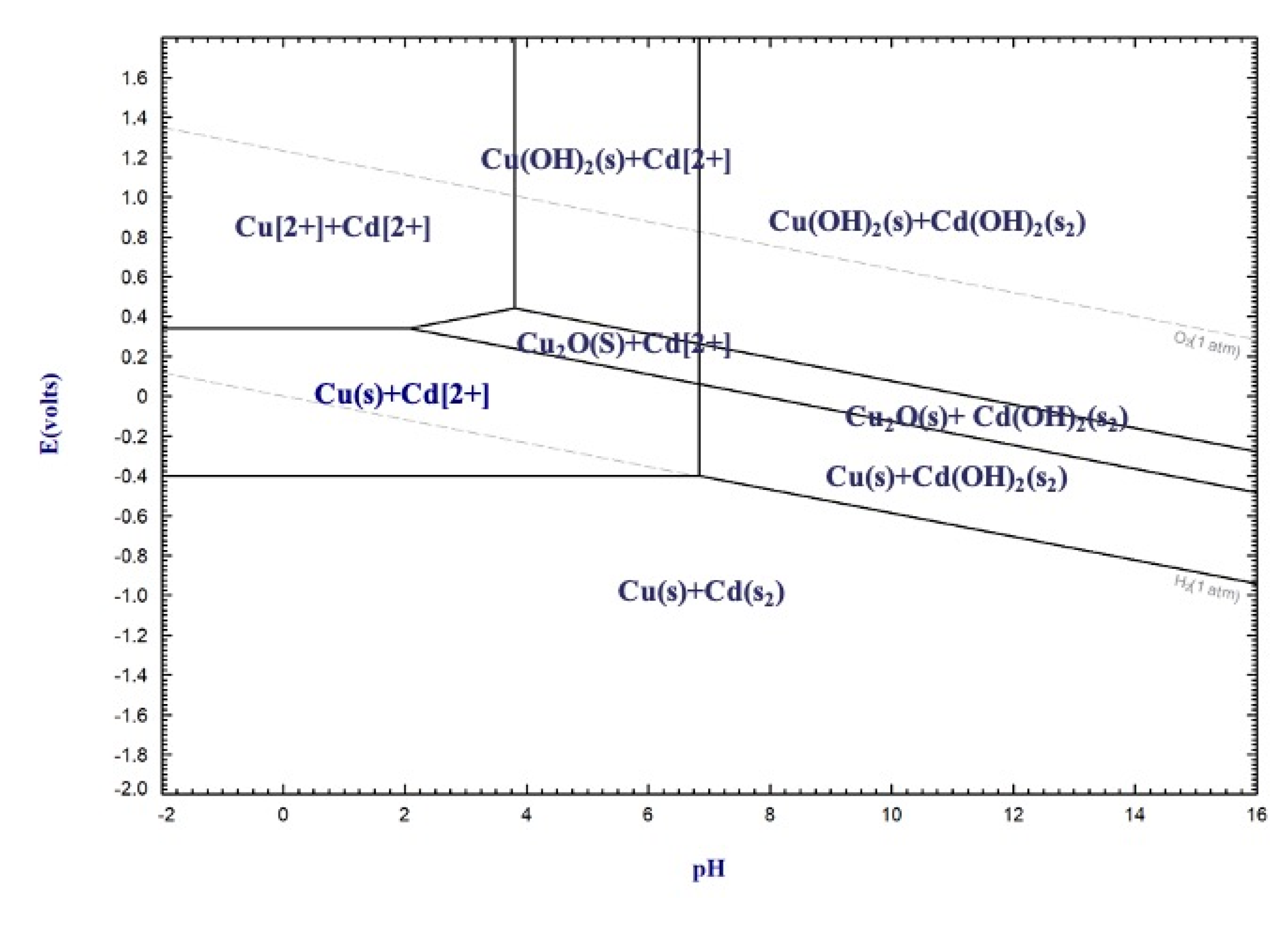
To study the thermodynamic properties of the cyclone electrolyte, the Factage7.3 thermodynamic software was used to calculate the thermodynamic behavior of the main ions in the electrolyte, and an E–pH diagram of the Cu-Cd-H2O system in the standard state was drawn.
As shown in Figure 3, the temperature is 298.15 K, and all ions are in the standard state. You can see that visually by looking at the E–pH diagram. The electrode potential of Cd was more negative than that of Cu, so Cu precipitated more than Cd. As can be intuitively seen from the E–pH diagram, the electrolyte had to be acidic (pH less than 3) in order to achieve Cu deposition. From the thermodynamic point of view, Cu was precipitated first and H+ was precipitated later in the electrolyte system. Cu2O may have been precipitated when the pH of the solution was slightly increased, and Cd may have been precipitated after H+. When the pH of the solution was slightly increased, the current efficiency was reduced due to the addition of cadmium ions, and oxide deposition may have occurred. After a period of electrode reaction, the reaction rate at the electrode/solution interface was not fast enough and the electrode potential deviated from the equilibrium potential, thus resulting in an overpotential phenomenon. Cd could have been precipitated on the cathode due to overpotential. The estimation of overpotential is called the Tafel equation.
η = a + b l n ( j [ j ] )
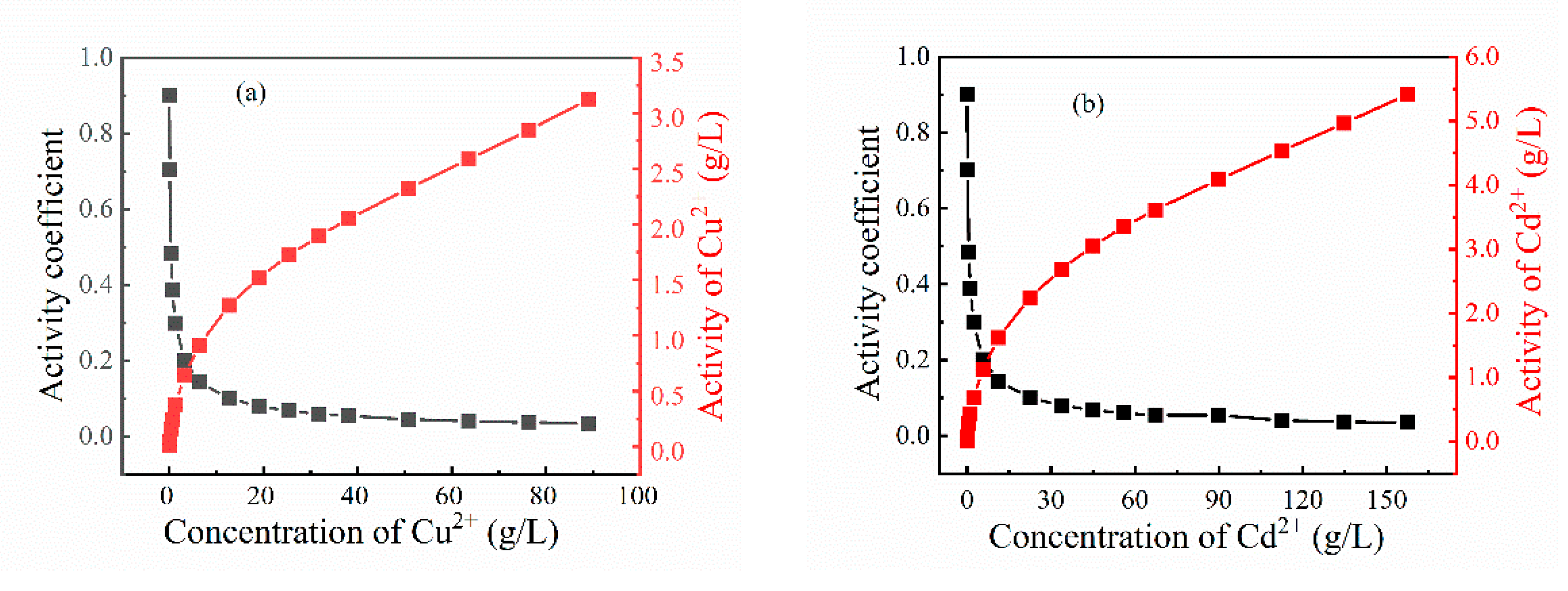
where η is the overpotential, a and b are the electrochemical constants related to the system, j is the current density, and [j] is the unit of j. This shows that the overpotential of H is higher at a higher current flux, so it is more difficult for H to precipitate. The metal precipitation on the electrode usually has less overpotential. In addition to the overpotential, many factors affects the electrode potential of Cu, such as the anion system and activity coefficient [28]. The results showed that the electrode potential in this study was about 0.2694 V. Pizer has made a great contribution to the activity coefficients of ions in aqueous solutions [29,30,31,32]. The thermodynamic model is suitable for high-concentration metal sulfate solutions and covers many ions (such as Cu2+ and Cd2+). The activity coefficients of Cu and Cd sulfate solutions were calculated by the Pitzer model, and the relationship between activity and concentration can be seen in Figure 4.
As can be seen from the Figure 4, at a lower concentration, the activity coefficient was larger and the activity changed with the concentration. It can be seen that in the case of low electrolyte concentration that because the activity had a large response to the concentration, the lower concentration caused a large change of activity, thus reducing the reaction rate and reaction limit. This indicates that in the later stage of the copper electrodeposition, the reaction rate was very slow in the electrolyte with a low copper concentration, which also affected the removal limit of copper. The variation trend of Cd and Cu was the same, and the effect of Cd on Cu electro integration may have followed this law. The concentration of Cd did not change much because of its negative electrode potential in the dielectric. However, at higher concentrations, small changes had little effect on the activity, so the effect should have been regular. However, different initial concentrations of Cd had different effects on Cu. Due to the change of kinetic conditions, local thermodynamic disequilibrium was inevitably caused in the electrolysis process, especially in places that were not uniformly concentrated. Though the swirl electrode could eliminate the concentration polarization to a certain extent, the diffusion phenomenon still existed in the layer of the electrode. Therefore, in the process of electrodeposition, a small amount of Cd was deposited on the cathode copper, thus affecting the quality of copper.

3.2. Cu Cyclone Electrowinning

3.2.1. First Stage of Cyclone Electrowinning

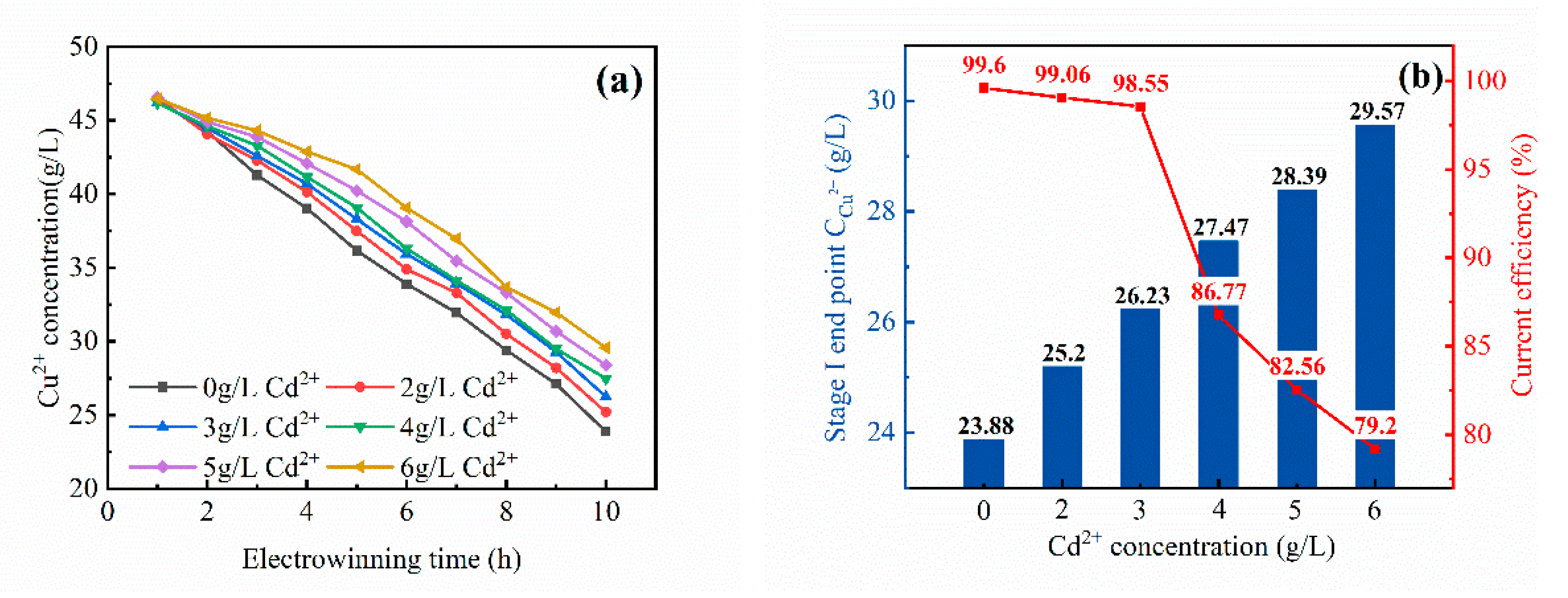
The concentration of Cu2+ in the electrolysis solution of stage I with the addition of different concentrations of Cd2+ is shown in Figure 5a. The concentration of Cu2+ in the copper electrolyte gradually decreased with the process of electrodeposition. The higher the amount of Cd2+, the higher the concentration of Cu2+ at the same electrodeposition time and the lower the rate of Cu2+ electrodeposition. This was because the addition of Cd2+ weakened the electrochemical reaction of Cu2+ on the cathode, thus reducing the attenuation rate of Cu2+ in the solution and indicating that Cd2+ reduced the electron absorption ability of Cu2+ and the rate of copper cathode generation to a certain extent.
After the end of a stage of electrodeposition, the concentration of Cu2+ increased with the increase of the addition amount of Cd2+ (Figure 5b.). In the case of the same initial Cu2+ concentration, according to copper electrodeposition rate of Equation (2), the removal rate of Cu2+ decreased with the increase of the Cd2+ concentration, and the copper electrodeposition rate decreased from 52 to 40%. The purity of cathode copper was measured by ICP-AES. The purity of the cathode copper was 99.63% in Table 1. This indicated that the content of Cd2+ did not affect the purity of the final cathode copper products but mainly affected the rate of electrodeposition of Cu2+ in the solution. In Figure 5b, it is shown that the current efficiency of cyclone electrodeposition decreased with the increase of the Cd2+ addition. The current efficiency decreased from 99.6 to 79.2%.
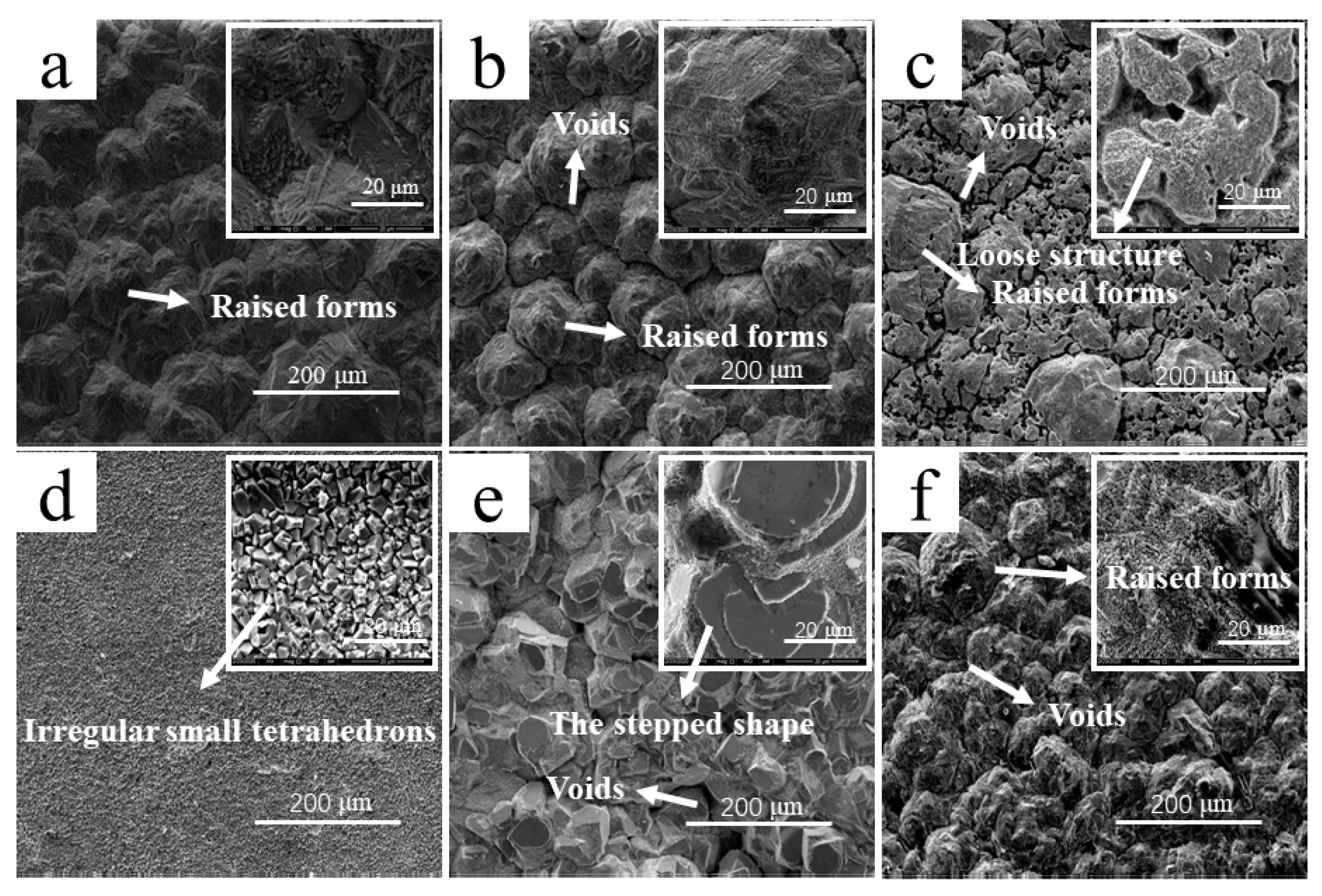
In the cathode copper product shown in Figure 6, it can be seen that the added Cd2+ concentration did not affect the macro morphology of the cathode copper, as all concentrations produced dense copper sheets that were visible to the naked eyed. To observe the crystal morphology of Cu2+, the micromorphology of the cathode copper products was observed by SEM.
It can be seen from Figure 6a that the microscopic morphology of the cathode copper sheet produced in a stage of electrodeposition without adding Cd2+ was comprised of polyhedral nodules [33] on the cathode. During the electrodeposition, the copper crystal spread all over the polyhedral nodules and produced a dense copper surface with a few remaining visible cracks and pores [34]. After adding a small amount of Cd2+, a small number of visible cracks and pores were generated in the crystallization bonding part of each curved surface based on this microscopic morphology (Figure 6b). With the increase of the addition amount of Cd2+, the copper crystals became no longer compact but formed an uncompact and nonhomogeneous structure [35], and the generated cracks and pores also became larger (Figure 6c). According to the image (Figure 6d) of the cathode copper sheet obtained by adding 4 g/L Cd2+, it can be seen that its morphology generated polyhedral crystals with shape edges [34] and spread across the whole cathode. The addition of Cd2+ made the irregular polyhedral crystals smaller in volume, and it could be seen that its crystallization rule was covered by copper layer by layer of crystal, thus generating the stepped shape in the picture (Figure 6e). The Cd2+ in Figure 6f caused a large number of fine polyhedral crystals to overlay the spherical nodules.
The main factors affecting the electron crystallization included current efficiency, temperature, agitation, and hydrogen ion concentration. As the electrodeposition proceeded, the temperature of the electrolyte increased and the increase in temperature caused many properties to change in the solution—the increase of electrical conductivity, the change of ion activity in solution, the change of the discharge potential of the existing ions, the decrease of metal precipitation, and the release of overprint all could have promoted the deposition of coarse crystallization. As the electrodeposition proceeded, H+ discharged in the solution, and the H+ content increased. Then, hydrogen was generated to discharge the gas from the electrolyte, and the hydrogen ion concentration in the solution decreased. The hydrogen ion concentration and pH value of a solution are extremely important factors that affect the electrolytic crystallization process. In this study, when the activity of hydrogen ions was high enough and the possibility of cladding was small, a lustrous and uniform deposit could be obtained. When the concentration of H+ decreased (pH increased), it formed a spongy deposit that could not adhere to the cathode well. Therefore, layered irregular polyhedral crystals were generated during crystallization, resulting in this kind of loose and dense crystalline morphology.

3.2.2. Second Stage of Cyclone Electrowinning

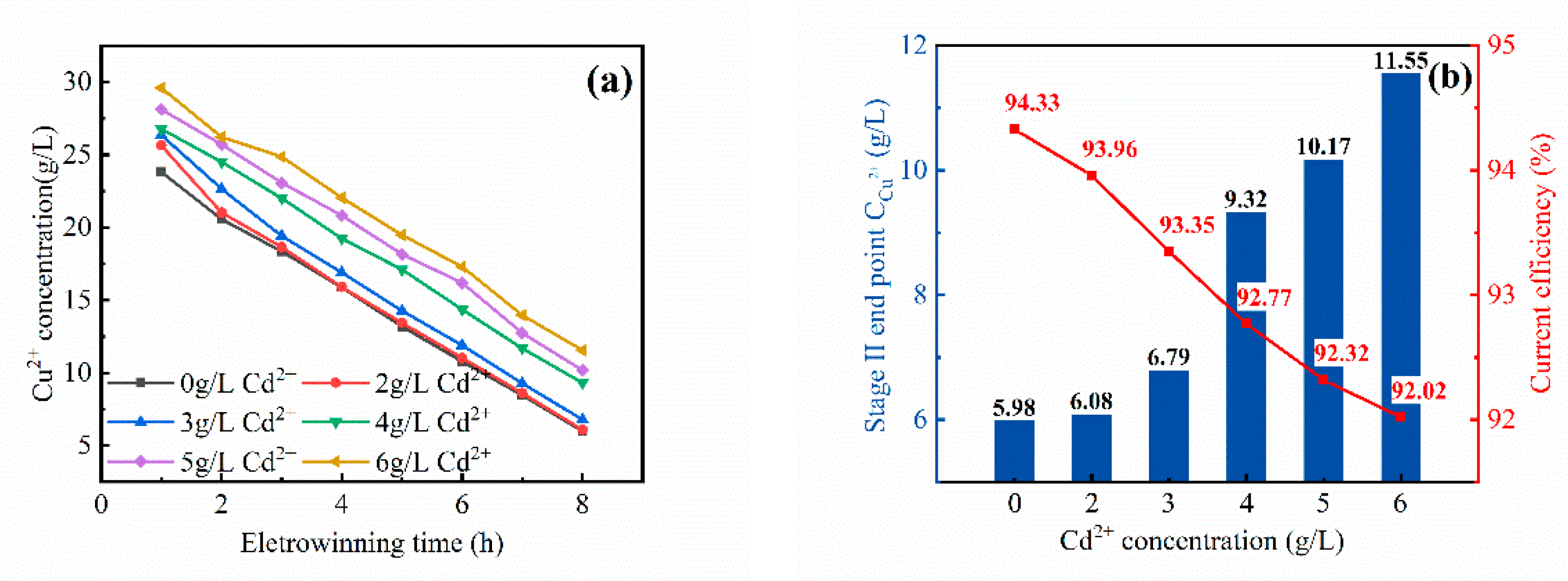
The concentration of Cu2+ in the electrolysis solution of stage II with the addition of different concentrations of Cd2+ is shown in Figure 7a. In the stage II electrodeposition of the copper electrolyte, the concentration of Cu2+ decreased with the process of electrodeposition, and the rate of electrodeposition of copper electrolyte with different Cd2+ concentrations was similar. When the concentration of Cu2+ was less than 30 g/L, the effect of Cd2+ on the copper electrodeposition rate was not obvious: the addition of Cd2+ weakened the electrochemical reaction of Cu2+ on the cathode to some extent and reduced the quality of the copper cathode.
After the stage II electrodeposition, the terminal Cu2+ in the electrolyte increased with the increase of the addition amount of cadmium (Figure 7b). According to copper electrodeposition rate formula (Equation (2)), the copper electrodeposition rate decreased from 88 to 77% with the increase of Cd2+ concentration. ICP-AES was used to detect the purity of the cathode copper plates. All the cathode copper products were standard cathode copper products. In Table 2, the purity of cathodic copper products obtained by two-stage electrodeposition reached more than 97%, indicating that Cd2+ did not enter the cathodic copper products. The cyclone electrodeposition technology also had good ion selectivity when the concentration of Cu2+ was low. In Figure 7b, it is shown that the Cd2+ had no obvious effect on the current efficiency of the second stage, with only a slight decrease visible. The current efficiency decreased from 94.33 to 92.02%.
The cathode copper plate produced by the second stage was also dense, but the brightness of the copper plate generated by the second stage was reduced compared with the gloss of the first stage. The crystallization mode of its microscopic morphology was observed by SEM, as shown in Figure 8.
The micro-morphology of cathode copper obtained by the electrodeposition of copper electrolyte without adding Cd2+ showed that the copper crystal nuclei were one-by-one spherical nodules [34] without any cracks and pores (Figure 8a). With the addition of Cd2+, some clear grain refinements [36] were generated based on the spherical nodules [34]. The more Cd2+ that was added, the finer the sediments that were generated on the compact surface and the larger the pores between each crystal (Figure 8b–f).
This was because there were two parallel processes in the formation of cathode deposits: nucleus formation and crystal growth. In the beginning, metals were not deposited on the entire surface of the cathode, only at individual points where a minimum activation energy was required for cationic discharge. The crystal of the deposited metal was first formed on the edges and corners of the main metal crystal of the cathode. In the electrolyte near the cathode part of the formed crystal, the ion concentration of the deposited metal was depleted so that new crystal nuclei were generated at the edge of the main metal crystal of the cathode, and the generated scattered crystal nuclei gradually increased until the entire surface of the cathode was covered by the sediment. With the progress of electrodeposition and the increase of Cd2+ addition, copper metal existed in the form of complexions in the solution. The increase of cadmium increased the reduction overpotential of Cu2+ in the electrolyte, and the reduction overpotential of Cu2+ was quite large, resulting in the formation of extremely fine crystalline sediments. The relationship between the number of crystal nuclei and the polarization value was that the greater the polarization value was, the finer the particles that were precipitated out of the sediment.

3.2.3. Third Stage of Cyclone Electrowinning

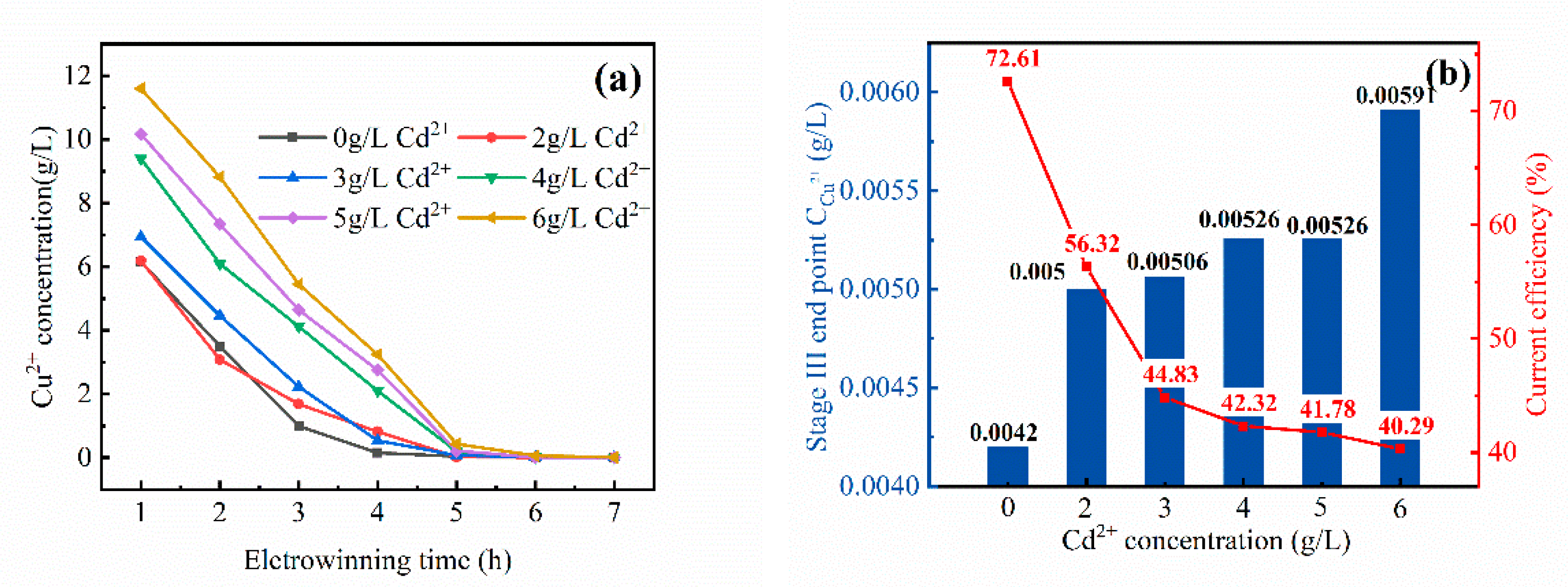
The concentration of Cu2+ in the electrolytes of stage III electrodeposition with different concentrations of Cd2+ is shown in Figure 9a. Similarly, the concentration of Cu2+ in the electrolyte decreased with the three-stage electrodeposition. The higher the addition amount of Cd2+, the longer the end time of the electrodeposition and the lower the rate of the whole electrodeposition. The addition of Cd2+ weakened the electrochemical reaction of Cu2+ on the cathode and reduced the attenuation rate of Cu2+ in the solution, the ability of copper ions to absorb electrons was reduced to a certain extent, and the rate of copper cathode formation was reduced.
After three-stage electrodeposition, the concentration of Cu2+ at the end of the solution increased with the increase of the addition amount of Cd2+ (Figure 9b), though it remained below 0.006 g/L—which was negligible compared with the initial concentration of the three-segment electroproduction. Therefore, the copper electrodeposition rate of the three-stage electrodeposition decreased with the increase of cadmium ion concentration. According to Equation (2), the electrodeposition rate of Cu2+ was able to reach more than 99.99% after three stages of electrodeposition, as detected by ICP-AES. According to Table 3, the purity of cathode copper products obtained after the three-stage electrodeposition was able to reach more than 92%. Cd2+ rarely entered the cathode copper products. When the concentration of target Cu2+ in the electrolyte was about 10 g/L and the content of impure Cd2+ metal ions was almost unchanged, the cyclone electrodeposition technology still had a high selectivity. In Figure 9b, it is shown that the current efficiency of cyclone electrodeposition decreased with the increase of the Cd2+ addition. The current efficiency decreased from 72.61 to 40.29%.
At the end of the three-stage electrodeposition, the copper electrolyte without the addition of Cd2+ and a small addition of Cd2+ resulted in the cathode copper plate, and black copper powder was produced after the electrodeposition with an increased amount of Cd2+. Therefore, two pieces of cathode copper and one segment of black copper powder were obtained for scanning electron microscopy to observe their microscopic morphology.
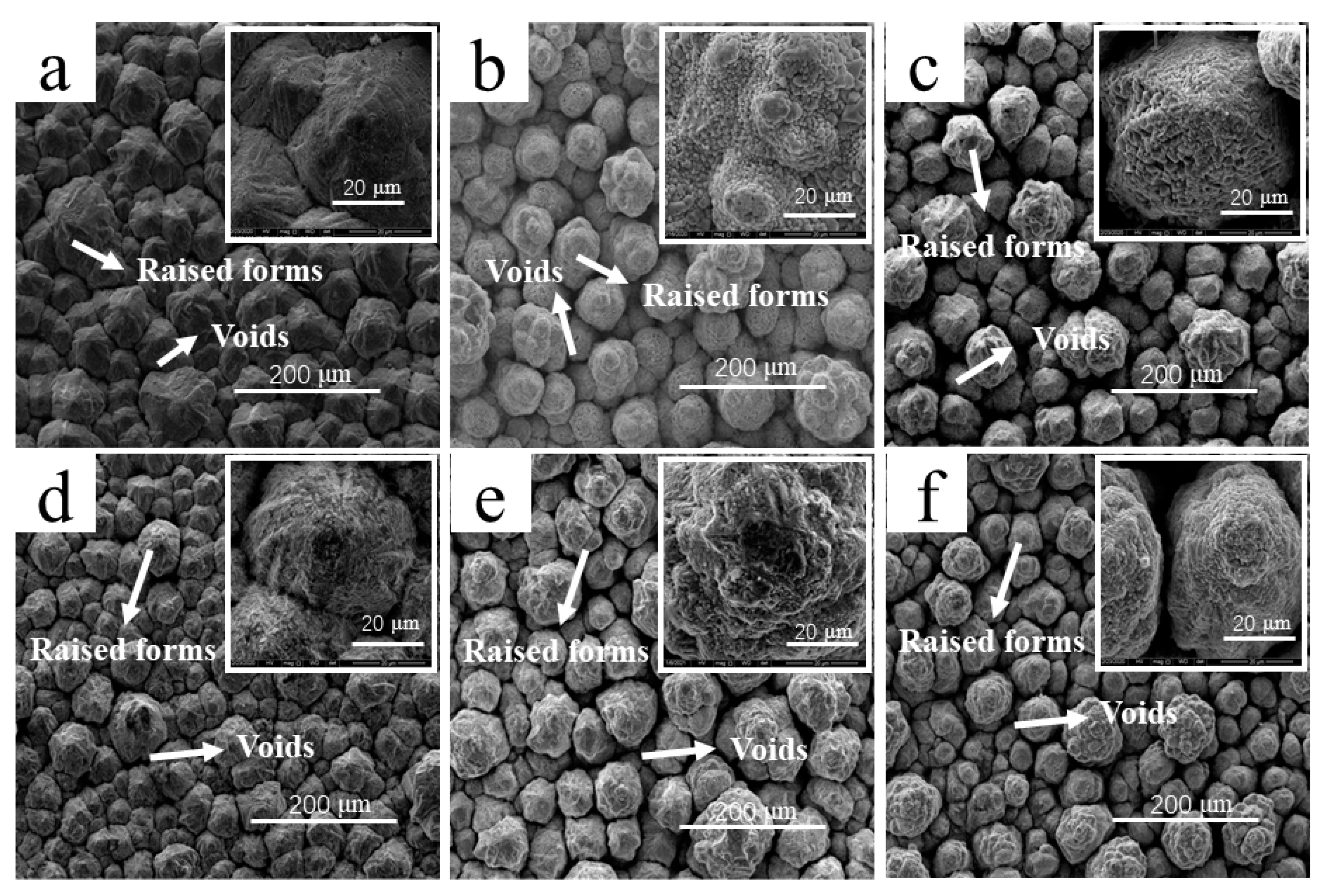
In the scanning electron microscopy images shown in Figure 10a, it can be seen that the microstructure of the cathode copper sheet produced in the stage of electrodeposition without adding Cd2+ had a raised growth on the cathode. With the electrodeposition, copper crystals spread all over the raised structure, resulting in a dense copper surface and a small number of raised forms that were similar to the microstructure of the first and second copper sections electrodeposited by the pure copper electrolyte. In Figure 10b, the microscopic morphology of the copper sheet in the three sections electrodeposited with the addition of Cd2+ can be seen to be of irregular polyhedral crystals [35] that were formed on the cathode and grew into dendrite grains [34]. It can be seen from the figure that the coarse copper powder particles also generated irregular spherical nodules [35] after amplification, and tetrahedron crystals grew into raised structures in a certain order (Figure 10c).
The kinetic study of the electro crystallization process showed that a large number of small crystals could be obtained by increasing the cathode polarization, i.e., the overpotential was the main factor affecting the kinetics of the electron crystallization. The addition of Cd2+ promoted the chemical transformation of the reactive ions near the electrode surface. As a result, the generated cathode copper plate showed such irregular small particles mentioned above, the gap was larger, and the crystallization was relatively loose.
After the completion of the three stages of copper removal by the cyclone electrodeposition technology, the effect of Cd2+ on the concentration of Cu2+ at the end of the electrodeposition of copper electrolyte was small and negligible. Therefore, the Cd2+ generation rate of the copper electrolyte slightly decreased, but the total current efficiency obviously decreased with the increase of Cd2+ from 87.22 to 73.39%. The addition of Cd2+ did not affect the copper formation rate, which was about 99.99%.

4. Conclusions

  • The addition of Cd2+ had little effect on the purity of the cathode copper sheet produced by cyclone electrodeposition of a copper electrolyte. High-purity cathode copper, standard cathode copper, and coarse copper powder with purities over 99.9, 99, and 98%, respectively, were obtained by three-stage electrodeposition, which realized the separation of Cu and Cd.
  • With the increase of the Cd2+ content in the electrolyte, the current efficiency of cyclone electrodeposition and the electrodeposition rate of the copper electrolyte showed different rules. The current efficiency of the first stage decreased from 99.6 to 79.20%. The current efficiency of the second stage had no change from 94.33 to 92.02%. The three-stage current efficiency decreased from 72.61 to 40.29%. The electrodeposition rate of copper in the first stage decreased from 52 to 40%. The second-stage electrodeposition rate decreased from 88 to 77%. The electrodeposition rate of the three sections had basically no change, can reach 99%.
  • The addition of Cd2+ had a great influence on the microstructure of the cathode copper. The cathode copper products with a high Cd2+ concentration had more small grains, and their overall density decreased. This may have been because the concentration of Cd2+ affected the electrodeposition state of the cathode and led to the decrease of the copper plate mass.

Author Contributions

Conceptualization, Y.W. and B.L.; methodology, Y.W.; software, Y.W.; validation, Y.W., J.G.; formal analysis, Y.W.; investigation, Y.W.; resources, H.X.; data curation, Y.W.; writing—original draft preparation, Y.W.; writing—review and editing, Y.W.; visualization, Y.W.; supervision, Y.W.; project administration, Y.W.; funding acquisition, B.L. All authors have read and agreed to the published version of the manuscript.

Funding

Financial support for this study was supplied from the National Natural Science Foundation of China (Project No. 51764035) and the Natural Science Foundation of Yunnan province (Project No. 2018FB089).

Informed Consent Statement

Informed consent was obtained from all subjects involved in the study.

Conflicts of Interest

The authors declare no conflict of interest.

References

  1. Tian-Cong, Z. Heavy Metal Metallurgy; Metallurgical Industry Press: Beijing, China, 1981. [Google Scholar]
  2. Zhai, X. Heavy Metal Metallurgy; Metallurgical Industry Press: Beijing, China, 2011. [Google Scholar]
  3. Dupeux, M. Science des Matériaux; Dunod: Paris, France, 2004. [Google Scholar]
  4. Barragan, J.A.; De León, C.P.; Castro, J.R.A.; Peregrina-Lucano, A.; Gómez-Zamudio, F.; Larios-Durán, E.R. Copper and Antimony Recovery from Electronic Waste by Hydrometallurgical and Electrochemical Techniques. ACS Omega 2020, 5, 12355–12363. [Google Scholar] [CrossRef]
  5. Guo, X.; Qin, H.; Tian, Q.; Li, D. Recovery of Metals from Waste Printed Circuit Boards by Selective Leaching Combined with Cyclone Electrowinning Process. J. Hazard. Mater. 2020, 384, 121355. [Google Scholar] [CrossRef]
  6. Oishi, T.; Yaguchi, M.; Takai, Y. Hydrometallurgical Recovery of High-Purity Copper Cathode from Highly Impure Crude Copper. Resour. Conserv. Recycl. 2021, 167, 105382. [Google Scholar] [CrossRef]
  7. Lee, C.-H.; Chang, C.-T.; Fan, K.-S.; Chang, T.-C. An Overview of Recycling and Treatment of Scrap Computers. J. Hazard. Mater. 2004, 114, 93–100. [Google Scholar] [CrossRef] [PubMed]
  8. Brar, K.K.; Magdouli, S.; Etteieb, S.; Zolfaghari, M.; Fathollahzadeh, H.; Calugaru, L.; Komtchou, S.-P.; Tanabene, R.; Brar, S.K. Integrated Bioleaching-Electrometallurgy for Copper Recovery—A Critical Review. J. Clean. Prod. 2020, 291, 125257. [Google Scholar] [CrossRef]
  9. Li, H.; Oraby, E.; Eksteen, J. Recovery of Copper and the Deportment of other Base Metals from Alkaline Glycine Leachates Derived from Waste Printed Circuit Boards (WPCBs). Hydrometallurgy 2020, 199, 105540. [Google Scholar] [CrossRef]
  10. Jiang, Q.; Song, X.; Liu, J.; Shao, Y.; Feng, Y. In-situ Cu (II) Enrichment and Recovery from Low-Strength Copper-Laden Wastewater Using a Novel Electrically Enhanced Microbial Copper Recovery Cell (MCRC). Chem. Eng. J. 2020, 382, 122788. [Google Scholar] [CrossRef]
  11. Rudnik, E.; Nikiel, M. Hydrometallurgical Recovery of Cadmium and Nickel from Spent Ni–Cd Batteries. Hydrometallurgy 2007, 89, 61–71. [Google Scholar] [CrossRef]
  12. Jajuli, M.N.; Mohamed, N.; Suah, F.B.M. Electrochemical Removal of Cadmium from a Sulphate Solution Using a Three-Dimensional Electrode. Alex. Eng. J. 2020, 59, 4237–4245. [Google Scholar] [CrossRef]
  13. Tran, T.K.; Kim, N.; Le, Q.C.; Nguyen, M.T.; Leu, H.J.; Thi, K.N. Electrochemical preparation and characterization of polyaniline enhanced electrodes: An application for the removal of cadmium metals in industrial wastewater. Mater. Chem. Phys. 2021, 261, 124221. [Google Scholar] [CrossRef]
  14. Li, H.; Zha, J.; Zhang, H.; Zheng, N.; Guo, G. Design Method for Cadmium and Arsenic Contamination Control during the Mining-Selecting-Backfilling Integrated Technology. J. Clean. Prod. 2020, 261, 121259. [Google Scholar] [CrossRef]
  15. Tang, S.; Chen, K.; Wan, N.; Ni, T.; Zhang, Y. Study on Extraction of Sponge Cadmium from Copper Cadmium Slag. Min. Metall. 2014, 23, 65–68. [Google Scholar]
  16. Yang, W.; Sun, L.; Hu, Y.; Yang, Y.; Jiang, X.; Wang, H. Cyclone Electrowinning of Antimony from Antimonic Gold Concentrate Ores. In TMS Annual Meeting & Exhibition; Springer: Berlin, Germany, 2018; pp. 143–154. [Google Scholar]
  17. Xu, H.; Li, B.; Wei, Y.; Wang, H. Extracting of Copper from Simulated Leaching Solution of Copper-Cadmium Residues by Cyclone Electrowinning Technology. Hydrometallurgy 2020, 194, 105298. [Google Scholar] [CrossRef]
  18. Wang, Y.; Xue, Y.; Su, J.; Zheng, S.; Lei, H.; Cai, C.; Jin, W. Efficient Electrochemical Recovery of Dilute Selenium by Cyclone Electrowinning. Hydrometallurgy 2018, 179, 232–237. [Google Scholar] [CrossRef]
  19. Jin, W. Simultaneous Phenol Detoxification and Dilute Metal Recovery in Cyclone Electrochemical Reactor. Ind. Eng. Chem. Res. 2019, 58, 12642–12649. [Google Scholar]
  20. Mooiman, M.B.; Ewart, I.; Robinson, J. Electrowinning Precious Metals from Cyanide Solution Using EMEW Technology. In Proceedings of the 142nd Annual Meeting of Society of Mining and Metallurgical Engineers, Denver, CO, USA, 24–27 February 2019. [Google Scholar]
  21. Junaedi, A.; Handoko, A.; Amin, M.; Sumardi, S.; Mufakhir, F.; Nurjaman, F.; Tandoko, A.; Supriyatna, Y. Nickel Production from Laterites Using Electro Metal Electrowinning (EMEW) Process. In IOP Conference Series: Materials Science and Engineering; IOP Publishing: Bristol, UK, 2019; p. 012016. [Google Scholar]
  22. Xu, Z.; Guo, X.; Tian, Q.; Li, D.; Zhang, Z.; Zhu, L. Electrodeposition of Tellurium from Alkaline Solution by Cyclone Electrowinning. Hydrometallurgy 2020, 193, 105316. [Google Scholar] [CrossRef]
  23. Wang, S. Recovering Copper Using a Combination of Electrolytic Cells. JOM 2002, 54, 51–54. [Google Scholar] [CrossRef]
  24. Li, B.; Wang, X.; Wei, Y.; Wang, H.; Barati, M. Extraction of Copper from Copper and Cadmium Residues of Zinc Hydrometallurgy by Oxidation Acid Leaching and Cyclone Electrowinning. Miner. Eng. 2018, 128, 247–253. [Google Scholar] [CrossRef]
  25. Sudibyo; Darmansyah; Junaedi, A.; Handoko, A.S.; Mufakhir, F.K.; Nurjaman, F.; Amin, M.; Supriyatna, Y.I.; Sumardi, S.; Salsabila, P. Nickel recovery from electrocoagulation sludge of hydrometallurgy wastewater using electrowinning. In Proceedings of the 3rd International Seminar on Metallurgy and Materials (ISMM2019): Exploring New Innovation in Metallurgy and Materials, Tangerang Selatan, Indonesia, 23–24 October 2019. [Google Scholar]
  26. Bae, M.; Kim, S.; Lee, J.-J. Gold Recovery from Waste Solutions of PCBs Gold Plating Process Using Hydro Cyclone Reactor for Demonstration Study. In Proceedings of the 3rd Pan American Materials Congress; Springer: Berlin, Germany, 2017; pp. 519–527. [Google Scholar]
  27. Jin, W.; Su, J.; Chen, S.; Li, P.; Moats, M.S.; Maduraiveeran, G.; Lei, H. Efficient Electrochemical Recovery of Fine Tellurium Powder from Hydrochloric Acid Media via Mass Transfer Enhancement. Sep. Purif. Technol. 2018, 203, 117–123. [Google Scholar] [CrossRef]
  28. Lu, X.H.; Maurer, G. Model for Describing Activity Coefficients in Mixed Electrolyte Aqueous Solutions. AIChE J. 1993, 39, 1527–1538. [Google Scholar]
  29. Pitzer, K.S. Thermodynamic Properties of Aqueous Solutions of Bivalent Sulphates. J. Chem. Soc. Faraday Trans. 2 Mol. Chem. Phys. 1972, 68, 101–113. [Google Scholar] [CrossRef]
  30. Pitzer, K.S. Thermodynamics of Electrolytes. I. Theoretical Basis and General Equations. J. Phys. Chem. 1973, 77, 268–277. [Google Scholar] [CrossRef] [Green Version]
  31. Pitzer, K.S.; Mayorga, G. Thermodynamics of Electrolytes. III. Activity and Osmotic Coefficients for 2–2 Electrolytes. J. Solut. Chem. 1974, 3, 539–546. [Google Scholar] [CrossRef] [Green Version]
  32. Clegg, S.L.; Pitzer, K.S. Thermodynamics of Multicomponent, Miscible, Ionic Solutions: Generalized Equations for Symmetrical Electrolytes. J. Phys. Chem. 1992, 96, 3513–3520. [Google Scholar] [CrossRef]
  33. Chai, L.; Xiong, C.; Zeng, W.; Wu, L.; Hu, H. The Role of Chelators in Electrodeposition of Cu-As Alloys from Copper Electrolyte. JOM 2020, 72, 3876–3886. [Google Scholar] [CrossRef]
  34. Jacobs, J.C.; Groot, D.R. Improving Cathode Morphology at a Copper Electrowinning Plant by Optimizing Magnafloc 333 and Chloride Concentrations. J. South. Afr. Inst. Min. Metall. 2019, 119, 983–987. [Google Scholar] [CrossRef]
  35. Nikoli, N.D.; Avramovi, L.; Ivanovi, E.R.; Maksimovi, V.M.; Ignjatovi, N. Comparative Morphological and Crystallographic Analysis of Copper Powders Obtained Under Different Electrolysis Conditions. Trans. Nonferrous Met. Soc. China 2019, 29, 1275–1284. [Google Scholar] [CrossRef]
  36. Wang, Y.; Li, L.; Wang, H. Recovery of Ni from the Acid Leaching Solution of Electroplating Sludge through Preparing Ni-Fe Alloy with the Addition of Saccharin Na First and then Thiourea. Electrochemistry 2018, 87, 8–13. [Google Scholar] [CrossRef] [Green Version]
Figure 1. Schematic diagram of cyclone electrodeposition apparatus: 1—anode; 2—cathode; 3—flow meter; 4—pump; 5—electrolysis device; and 6—storage setting tank.
Metals 11 00529 g001
Figure 2. The flow chart of copper electrodeposition process in the simulated electrolyte with added cadmium ions.
Metals 11 00529 g002
Figure 3. The E–pH diagram of the Cu-Cd-H2O system [24].
Metals 11 00529 g003
Figure 4. Activity coefficients of Cu and Cd sulfate solutions calculated by the Pitzer model and the relationship between activity and concentration: (a) activity coefficients of Cu; (b) activity coefficients of Cd.
Metals 11 00529 g004
Figure 5. The curve of Cu concentration, endpoint content, and current efficiency in the first stage of the cyclone electrowinning process: (a) Cu concentration; (b) Endpoint content and current efficiency.
Metals 11 00529 g005
Figure 6. The microscopic morphology of the cathode copper with different Cd2+ concentrations in the first stage of the cyclone electrowinning process: (a) 0 g/L, (b) 2 g/L, (c) 3 g/L, (d) 4 g/L, (e) 5 g/L, and (f) 6 g/L.
Metals 11 00529 g006
Figure 7. The curve of Cu concentration, endpoint content, and current efficiency in the second stage of the cyclone electrowinning process: (a) Cu concentration; (b) Endpoint content and current efficiency.
Metals 11 00529 g007
Figure 8. The microscopic morphology of the cathode copper with different Cd2+ concentrations in the second stage of the cyclone electrowinning process: (a) 0 g/L, (b) 2 g/L, (c) 3 g/L, (d) 4 g/L, (e) 5 g/L, and (f) 6 g/L.
Metals 11 00529 g008
Figure 9. The curve of Cu concentration, endpoint content, and current efficiency in the third stage of the cyclone electrowinning process: (a) Cu concentration; (b) Endpoint content and current efficiency.
Metals 11 00529 g009
Figure 10. The microscopic morphology of the cathode copper with different Cd2+ concentrations in the third stage of the cyclone electrowinning process: (a) 0 g/L, (b) 2 g/L, (c) 3 g/L.
Metals 11 00529 g010
Table 1. Copper purity of cathode with different Cd2+ concentrations in the first stage.
Metal Elements0 g/L2 g/L3 g/L4 g/L5 g/L6 g/L
Cu>99.7>99.7>99.7>99.7>99.799.63
Cd<0.001<0.0010.00110.00230.00260.0041
Table 2. Copper purity of cathode with different Cd2+ concentrations in the second stage.
Metal Elements0 g/L2 g/L3 g/L4 g/L5 g/L6 g/L
Cu>99.7>99.7>99.7>99.799.5197.7
Cd<0.001<0.0010.00230.004<0.010.012
Table 3. Copper purity of cathode with different Cd2+ concentrations in the third stage.
Metal Elements0 g/L2 g/L3 g/L4 g/L5 g/L6 g/L
Cu97.4796.1894.8294.2393.5692.98
Cd0.00150.0160.0190.02340.0410.056
Publisher’s Note: MDPI stays neutral with regard to jurisdictional claims in published maps and institutional affiliations.