Review

Perforated Plate for Ballistic Protection—A Review

by
Sebastian Balos
1,
Daniel Howard
2,
Adrian Brezulianu
3 and
Danka Labus Zlatanović
1,4,*
1
Department of Production Engineering, Faculty of Technical Science, University of Novi Sad, 21000 Novi Sad, Serbia
2
Howard Science Limited, Worcestershire WR14 2NJ, UK
3
Faculty of Electronics, Telecommunications and Information Technology, Technical University of Iasi, 700259 Iasi, Romania
4
Department of Production Technology, Technische Universität Ilmenau, 98693 Ilmenau, Germany
*
Author to whom correspondence should be addressed.
Metals 2021, 11(4), 526; https://doi.org/10.3390/met11040526
Submission received: 28 February 2021 / Revised: 14 March 2021 / Accepted: 17 March 2021 / Published: 24 March 2021

Abstract

:
In recent years, the interest of the scientific community in perforated plates for ballistic protection has increased. Perforated plates do not represent protection by themselves, rather, they are used in the armour systems of armoured vehicles, in conjunction with base armour, since they are intended to induce bend stresses, where a penetrating core fracture occurs. The fragments are subsequently stopped by base armoured vehicle armour. Although for the first time used several decades ago, perforated plates are found to be attractive even today. The main reason is the combination of very convenient properties. Besides high mass effectiveness, they possess a high multi-impact resistance, since their perforations arrest cracks. Therefore, a relatively wide array of materials is suitable for perforated plate fabrication, ranging from alloy steel to some types of cast iron. Being made of metallic materials, raw material costs are relatively low compared to ceramics or composite materials, making them very attractive for present and future armoured vehicles. Finally, armour system consisting of a perforated plate and base plate at some distance, reduce the effectiveness of both shaped charge jets and act as blast mitigators.

1. Introduction

Passive armour is aimed to withstand the impact of projectiles (shrapnel, bullets, missiles) and thus to protect represents the most important means of protecting the personnel and vehicle subsystems from enemy fire. There is a wide array of materials and configurations that can effectively be used as passive armour protection, Figure 1 [1,2]. Armour steel and aluminium alloys are structural materials and are usually supplemented by other types of armour, to facilitate a relatively high mass effectiveness. Moreover, typically ceramics, or metal matrix composites, represent a parasitic mass, that stresses the structural steel or aluminium alloy’s body of the vehicle [3,4,5]. Mass effectiveness (Em) is the ratio of the areal density of a reference armour (usually rolled homogenous armour—RHA) to the areal density of experimental armour [6]. Table 1, there are examples of armour materials and descriptive configurations with their thicknesses, areal densities and mass effectiveness.
Perforated plates represent a non-homogenous armour, usually employed as applique, or add-on armour of various armoured vehicles. They appear in predominantly light armoured vehicles, the widest type of armoured vehicles used. The application of non-homogenous vehicle armour dates back to World War II, when the German Schuerzen wire mesh appeared on a number of PzKpfw IV Ausf J [8] medium tanks. Thoma Schuerzen was initially added to provide increased protection against kinetic energy rounds fired from the Soviet 14.5 mm anti-tank rifles, but during its application, it also proved very effective against American M6 Bazooka-shaped charge anti-tank rocket launchers. Furthermore, its most important feature was its lightweight nature. It was approximately three times lighter than the admittedly more common Schuerzen homogenous mild steel spaced plates used on PzKpfw IV Ausf G and H from 1943. Instead of 8 mm mild steel plates in Schuerzen, a lighter mesh, made of 5.5 mm diameter mild steel wires at around 19 mm distance between wire axes was applied in Thoma Schuerzen. The main mechanism in both Schuerzen and Thoma Schuerzen was the induction of yaw in the projectile penetrating core, so base armour can provide full protection [9,10]. A lower stiffness of Thoma Schuerzen compared to Schuerzen was compensated by its non-homogenous structure, more effective in inducing yaw, and particularly, weight savings.
A similar type of non-homogenous armour appeared on Soviet T-34/85 tanks during the Battle of Berlin in 1945. It was in the form of bed frames with 1 mm diameter wire net to offer additional protection against shaped charges of German Panzerfaust recoilless weapons [11]. Panzerfaust used an early generation shaped—charge warhead, just as was the M6 Bazooka and the German Panzerschreck, both very sensitive to increasing stand-off distance. At longer standoff distances, the jet defocuses and even fragments, degrading penetration effectiveness. After World War II, more advanced shaped—charges with higher penetration were developed, so spaced armour began to gain favor, along with different improvised add-on armours to protect from shaped—charges, such as logs, rubber sheets and wire mesh nets used in a number of local wars [3,5,12].
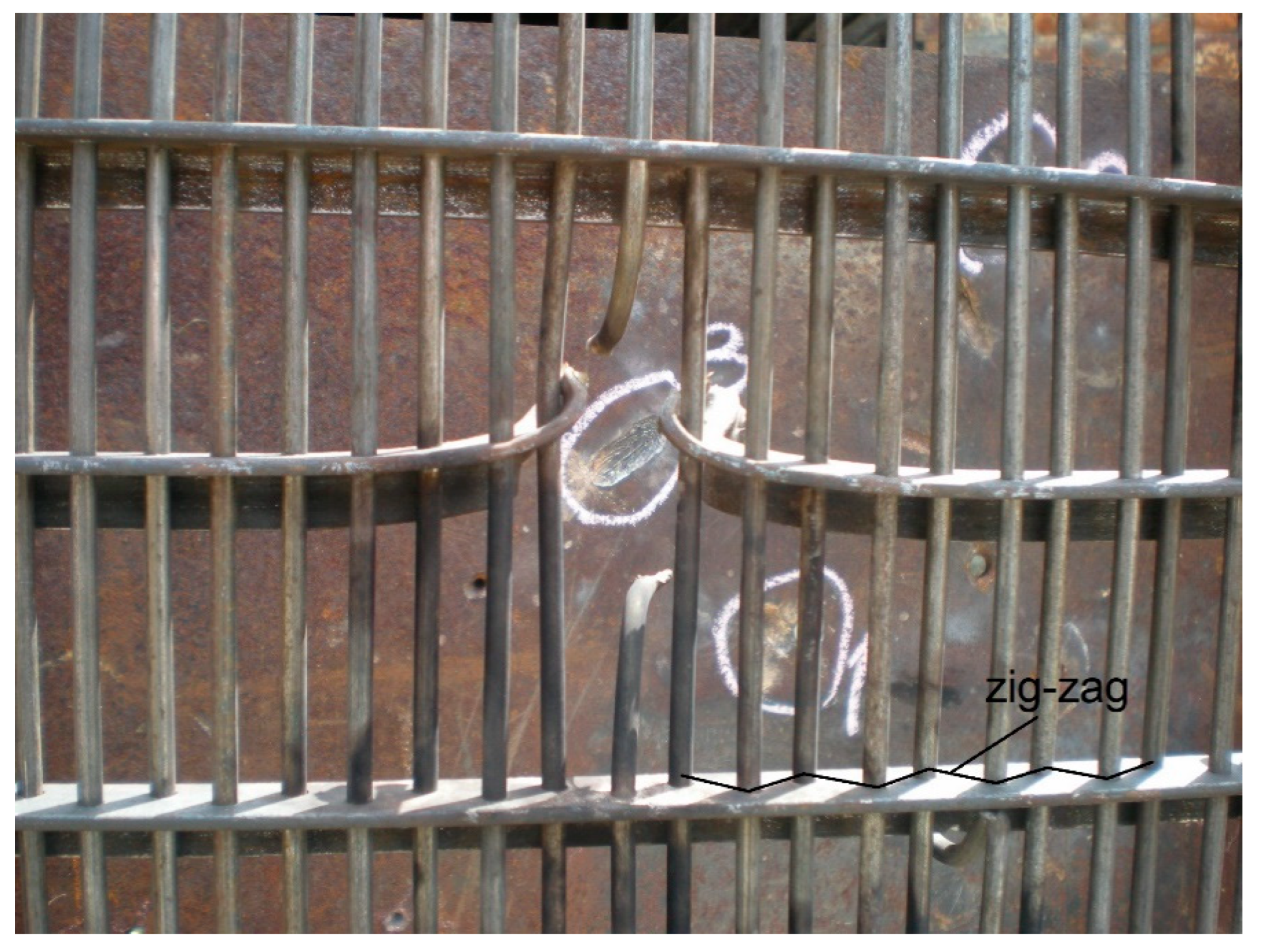
Recently, along with the tendency to use improvised add-on armours, there were attempts to develop wire meshes and fences from commercial off-the-shelf materials [13,14]. Balos et al. [13] have used the disrupting element of the fence made of Ø 5 mm patented wires containing 0.8% carbon (Rp0.2% = 1410 MPa; Rm = 1630 MPa; A = 9.5%). The distance between the wires was 13–13.5 mm, placed in an L-profile frame in zig-zagged (Figure 2) and parallel configurations. Wire fences were mounted in stiff and free-hanging mounting. Base RHA, 460 BHN hard, 13 mm thick was mounted at 400 mm from the mesh. In this study, only the parallel wire arrangement proved ineffective, with the main defeating mechanism being the induction of yaw. Zig-zagged and angled configurations were fully effective, fulfilling the ballistic protection criterion set at stopping all five kinetic energy shots from a Browning M2HB 12.7 mm heavy machinegun. These configurations proved to be superior since the case where the projectile impacts two wires at the same time is completely excluded. A similar effect was observed by Balos et al. [14] where an even simpler and cheaper configuration was successfully applied: Ø 6 mm mild steels wire mesh (Rp0.2% = 260 MPa; Rm = 380 MPa; A = 19%) with 50 mm distance between the wires was used to create a four-layer stepped-up multilayer mesh, with the distance between centers of wires of 16.75 mm. Having essentially a 3D configuration owing to the depth of the setup, a vertical mesh proved to be more effective than if inclined, which is quite opposite to results presented in the previous study [13]. The main reason for such behavior is the inclination itself. In such a setup, some inter-wire distances decrease, while others increase, representing a less effective yaw-inducer. To provide protection in such a configuration, an additional wire mesh layer might have been added, however, this could have only been done at the expense of an increase in weight.

2. Perforated Plates in Armoured Vehicles

One of the most effective light applique armour of the Cold War was the Israeli Toga, used on local modification of the American M113 armour personnel carriers (APC) Zelda-1 in 1972, one of the most widely used vehicles of this class. It consisted of perforated steel plates (~10 mm thick, with ~10 mm perforations with ~15 mm distance between their axes) all around the vehicle. When placed at some distance from the base armour, together with the base aluminium alloy (AA 5083) armour, it provided a significant increase in protection from 7.62 mm × 51 mm to 14.5 mm × 114 mm AP (Armor Piercing) ammunition [1,16]. This type of add-on armour was subsequently deployed for increasing the armour protection of other vehicles as well. Perhaps the most interesting being a range of Israeli heavy armoured personnel carriers (HAPCs) and even main battle tanks (MBTs) Merkava, the heaviest vehicle that uses this type of armour. In addition to this, perforated plates attracted considerable attention in other armed forces as well.
The American P900 type armour, consisted of two 500 BHN perforated plates 6.35 mm thick and appeared in two basic configurations. The first has the distance between perforated plates of 25 mm, with the inner perforated plate mounted at 182 mm distance from the base plate of the Dutch YPR-765 infantry fighting vehicle (IFV), itself a version of M113 APC. Again, in this vehicle, the base plate was AA 5083 aluminium alloy. The second configuration also consisted of two perforated plates placed at 22 mm distance between them, while the inner was mounted at 82 mm from the base aluminium alloy plate (M2/M3 Bradley), of AA 5083 aluminium alloy [17]. Howell et al. [18] successfully applied high manganese and aluminium austenitic steels as a basis for P900 perforated plate armour, effective against 7.62 mm AP ammunition.
United Kingdom has fielded an up-armoured light armoured fighting vehicle (AFV) Scimitar with perforated plates more similar in appearance to Toga [10]. Finally, there are indications that perforated plates were used in the Canadian version of the Leopard C2 main battle tanks (MBT). These perforated plates were coated in rubber and placed at turret sides. They were probably aimed at protecting the vehicle against 30 mm autocannon, due to a thicker base armour [10]. Although single or double perforated plates are the best known, an alternative approach was proposed in the patent by Auyer et al. [19]. In accordance with this patent, perforated plates with triangular holes were presented. Two such perforated plates were proposed to be mounted within the armour protection package in such a way, that hole patterns are offset in respect to each other. This was done so as to prevent straight-line penetration and facilitate the induction of asymmetric loading of the penetrating core of the projectile.
More specific data on perforated plate material was shared in [7,20]. It was claimed that M113 was being fitted with perforated plates made of MARS 300 ultra-high hardness steel, having the hardness of 578–655 BHN and relatively low Charpy impact strength at −40 °C of over 8 J. Although highly effective against 14.5 mm × 114 mm AP ammunition, the chemical composition with ≤0.55%C, ≤0.002%S, ≤0.01%P, ≤0.7%Mn, ≤1%Si, 2.4%Ni, ≤0.0.4%Cr and ≤0.5%Mo, provide carbon equivalent of CE ≤ 0.83 [21]. That means the welds are susceptible to cold cracking, rendering the overall weldability relatively low, suggesting bolting is the most convenient joining method. When combined with an aluminium alloy hull, inherent difficulties of joining steel and aluminium alloy due to the formation of intermetallic compounds (FeAl, Fe3Al, Fe2Al3, FeAl2, Fe2Al5, FeAl3, FeAl6) make the welding difficult in any case [22,23,24,25]. However, as ultra-high-strength steels prevail over aluminium alloys in today’s armoured vehicles, perforated plates are made of weldable high-hardness steels (500–550 BHN) but with a lower carbon content, also used for base armour, might be a more effective option.

3. Basic Principle

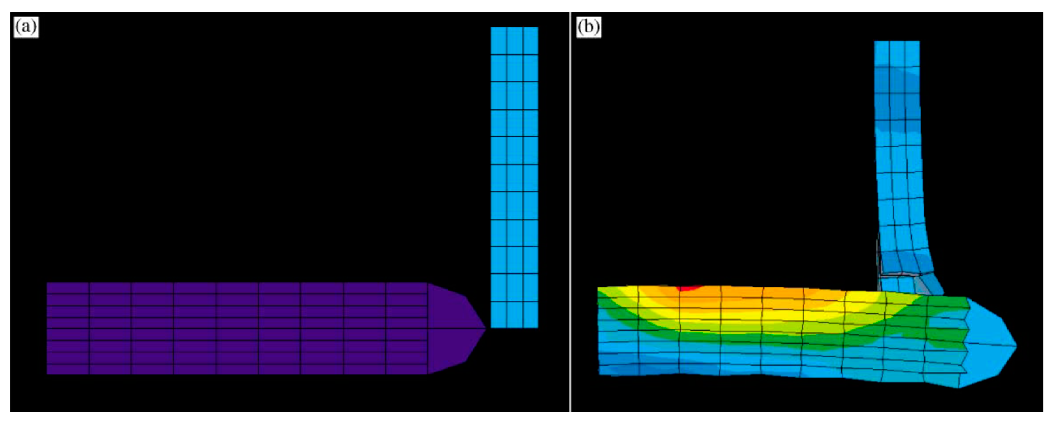
The study by Chocron et al. [26] proved the basic principles of perforated plates, by applying the three-dimensional numerical simulations with the AUTODYN-3D code (Ansys, Canonsburg, PA, USA). It was determined that 7.62 mm × 51 mm M2 armour-piercing (AP) round, when impacting the edge of the plate undergoes bending, Figure 3. It was found that 2% tensile strain is needed, representing a threshold over which the penetrating core of the projectile fractures. The penetrating core fracture is essential for a considerable reduction in penetration since the base plate can stop these fragments without significant damage. It must be noted that the penetrating core used in this test possessed a very high hardness of 62 HRC, which was necessary to provide sufficient penetration, however, that also means its ductility is relatively low, so even 2% strain is sufficient to fracture it. This relatively high hardness is characteristic of all AP, armour-piercing incendiary (API), armour-piercing tracer (APT) and armour-piercing incendiary tracer (APIT) penetrating cores of different ammunitions of different calibers. It was determined that the overlap threshold h/R is 0.34. Overlap threshold is important for correct geometry determination of the perforated plate: h—overlap between the penetrating core and the plate; R—radius of the penetrating core. In higher h/R values, no core fracture occurred, which means the induction of bend stress was not sufficient, since the projectile impacted the edge of the plate further away from the projectile point, that is, closer to the projectile cylindrical section. Numerical simulations done by Mubashar et al. [27] proved that the perforated plate causes the shattering of the projectile penetrating core into multiple fragments which were unable to penetrate the base armour plate. Furthermore, simulations done by Chocron et al. [26] proved that the induced strain increases with plate thickness. Computational data suggest that a strain of at least 2% is needed to cause the penetrating core fracture. In the case of 7.62 mm × 51 mm M2 AP ammunition used in the experimental part of this work, 3.175 mm perforated plate (Rp = 1400 MPa) is sufficient to effectively fracture penetrating core, which induces 2.5% strain, Figure 4. Aluminium alloy perforated plates were also tested (Rp = 380 MPa, 6.35 mm thick), which were not able to fracture the penetrating core, since the strain imparted to the penetrating core is slightly less than 2%. That means, either a stronger aluminium alloy is recommended, or a thicker perforated plate. The application of aluminium alloy perforated plate has merits, since its density is almost three times lower than that of steel [28], which, together with approximately twice the thickness theoretically needed to fracture the penetrating core, could result in significant savings in weight. Nevertheless, this remains to be addressed and ultimately experimentally proved. Furthermore, the joining of aluminium alloy to the steel vehicle hull would arise by bolting anyway, as is done traditionally with steel perforated plates. The main reason for this is the difficulties of aluminium alloy to ferrous alloys dissimilar welding, due to inherent difficulties of welding of high strength aluminium alloys themselves and the formation of Fe-Al intermetallics that severely degrade mechanical properties of welds, especially ductility [29,30,31].

4. Perforated Plate Geometry and Materials

The works of Balos et al. [32] and Radisavljevic et al. [33] represented continuous development efforts to optimize the material, geometry and mounting of perforated plates, in order to increase mass efficiency and multi-hit resistance of the perforated plate and armour system as well. Along with the performance of a particular perforated plate in terms of ballistic resistance, a number of interconnected holes and damaged areas were reported. The number of perforated plates and damaged areas was used to describe the multi-hit resistance, a significant advantage over less effective armour types in this respect, such as various types of RHA, and conventional ceramic tiles in particular [34,35,36] The base plate was 13 mm RHA, having a hardness of 460 BHN, while test ammunition was 12.7 mm × 99 mm M8 API. It was found that a perforation diameter lower than Ø 9 mm and thicknesses under 6 mm, proved ineffective in both inducing sufficient bed stresses to cause penetrating core fracture and preventing the API ammunition to penetrate base armour. On the other hand, these studies [33,37] have shown that larger perforations are more effective, due to a more potent bend stress induction potential.
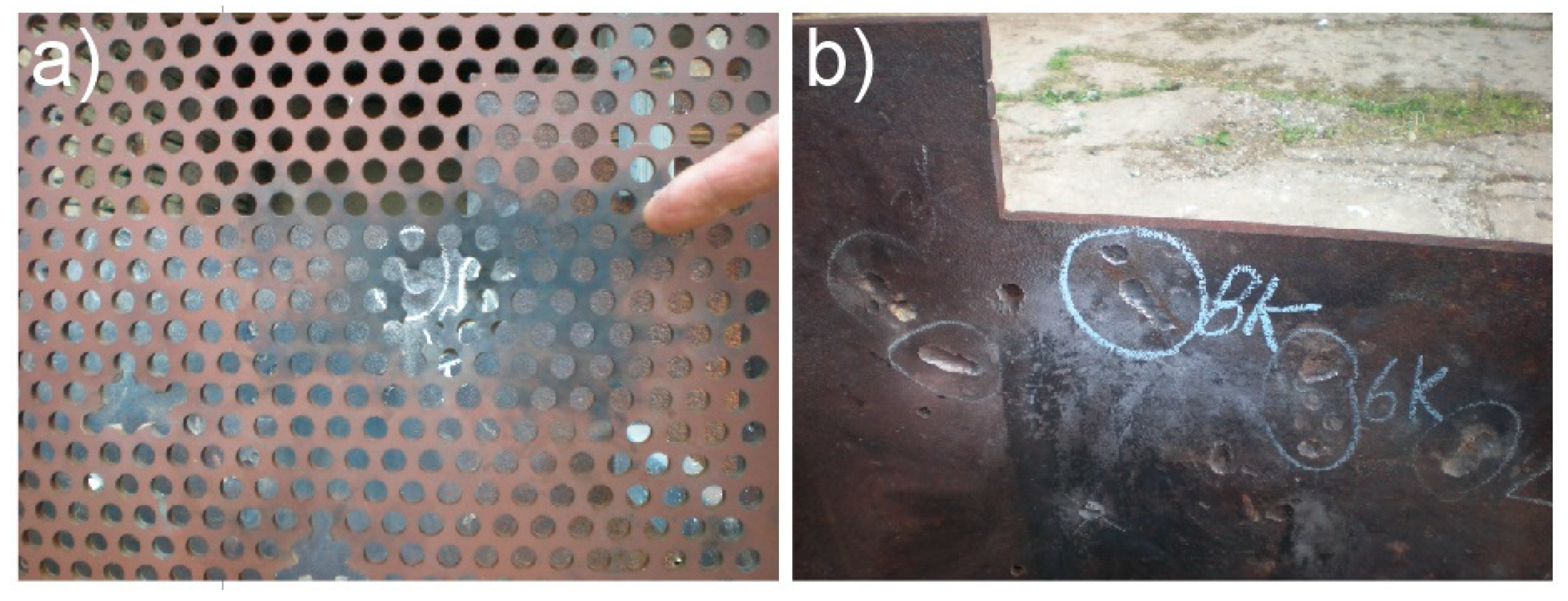
The depiction of various successful geometries is shown in Table 2. The main criterion for full ballistic protection was that no projectile penetrated the basic RHA plate (zero penetration criteria). Larger perforations (Ø 11 mm) resulted in a more effective fragmentation of the penetrating core: Ø 9 and 10 mm perforations resulted in fragmentation of the penetrating core into maximal five fragments, while perforations of Ø 11 mm caused the fracture of into maximal six parts, with a less severe base armour plate damage. That means, to achieve protection from a larger number of smaller fragments, a thinner and lighter base plate could be used, lowering the weight, and therefore, the areal density of the armour system. In addition to perforated plates made of different types of steels, the results depicting the geometry and effectiveness of heat-treated austempered ductile iron (ADI) and austempered compacted graphite iron (ACGI) perforated plates are also shown in Table 2, extracted from studies by Balos et al. [37,38]. Typical perforated plate and base plate damage (core fracture in two pieces) are given in Figure 5.
The average number of interconnected perforations in steel specimens drops as the perforations become larger for the same material (H9-6-0, H10-6-0, H11-6-0). However, a quite opposite trend can be observed in terms of the damaged areas. The main reason is the fact that perforations are larger, so that the damaged area increases. The average number of interconnected perforations is higher in cast irons (ADI-275, ACGI-275), but the main drawback is the damaged area which is significantly larger, potentially leaving larger unprotected areas that may not cause any interaction with the subsequently fired incoming projectile, which would most likely penetrate the base armour.
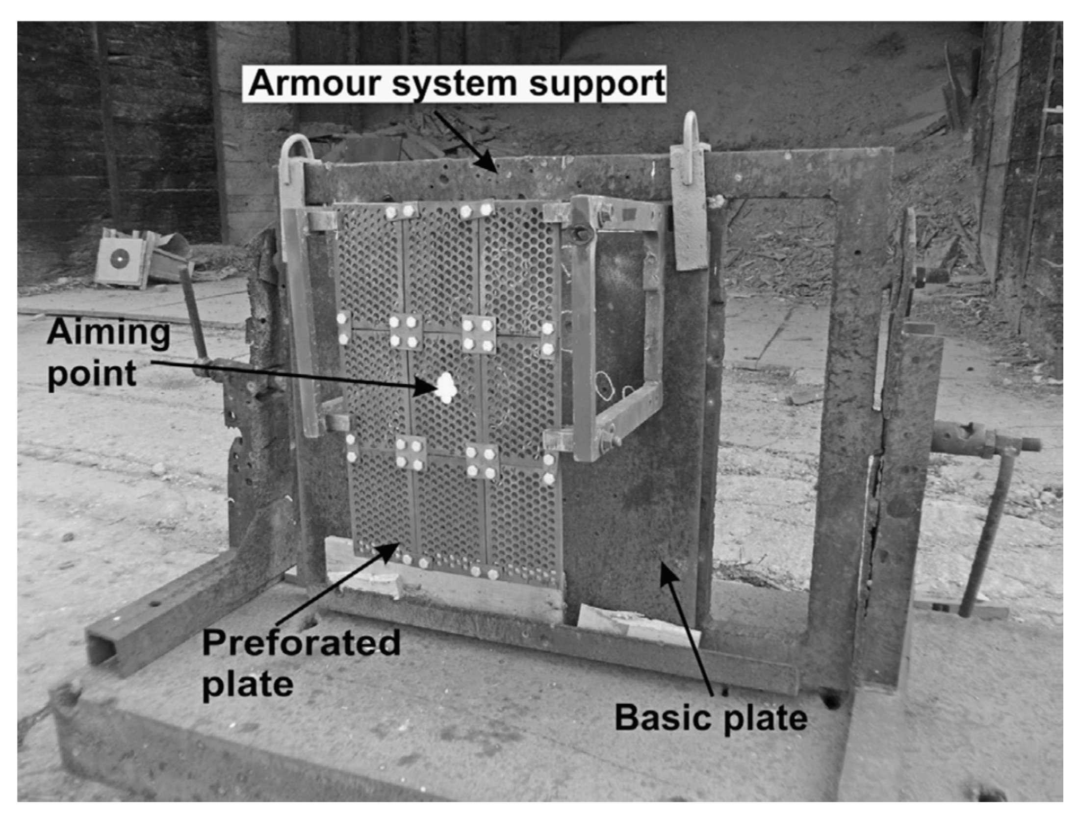
Higher mass effectiveness in perforated plates with larger perforations results in a smaller number of interconnected perforations, but on the other hand, the damaged area is larger, Table 2. It can be seen that cast irons (ADI and ACGI) represent an interesting alternative to steels, due to their relatively high tensile strength and a lower density. Considerably lower elongation, which represents the measure of the material’s ductility, does not affect these perforated plates’ mass effectiveness but lowers the perforated plate multi-impact properties. It must be noted that ADI-275 and ACGI-275 targets were not made of a single plate, but rather of several smaller (210 mm × 130 mm) plates bolted together, Figure 6. This was done due to the salt bath size available for specimen heat treatment. Areal density and mass effectiveness data for ADI-275 and ACGI-275 given in Table 2 do not take into account joining bolts and plates.
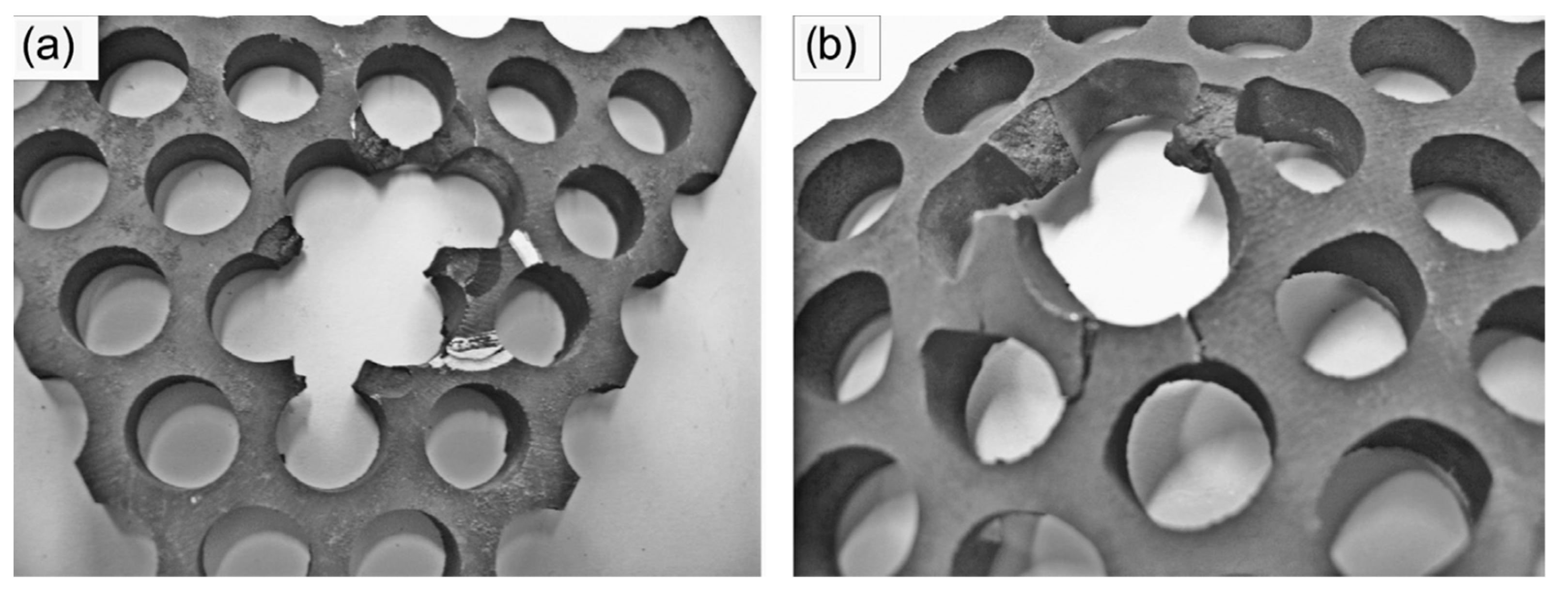
The particular design of perforated plates overcomes the problem in ductility, providing significant mass effectiveness, since the crack propagates to the nearest perforation, where it is stopped from further propagation. Typical damage in differently heat-treated ADI materials is shown in Figure 7. It can be seen that intensive cracking and no plastic deformation occur in ADI-275 material, which is in contrast to the softer and more ductile ADI-400 material. In spite of that, the results suggest that a softer and more ductile ADI-400 does not offer sufficient induction of bend stresses in the projectile penetrating core to cause its fracture or sufficient yaw to prevent it from penetrating the base armour. A lower density of ADI and ACGI materials was certainly beneficial since it enabled the increase in the thickness of cast iron perforated plates further adding to their bend stress induction potential and effectiveness. Probably the most significant advantage of cast materials such as ADI and ACGI is a relatively low cost compared to steel perforated plates, both in the simplicity of manufacture of the material itself and perforation fabrication. Namely, the fabrication by drilling of already heat-treated steels, particularly armour steels is very difficult, so a more expensive waterjet is usually applied. The logistics required for the manufacture of rolled steels is more significant than casting iron and steel [38,39].
Another approach is to apply a cheaper and quicker alternative to the waterjet process of perforated plate fabrication [40]. In this work, armour steel was subjected to a laser cutting process with three cutting speeds, 1000, 1200 and 1400 mm/min, with a respective number of perforations drilled: 80, 100 and 120 min−1. In this study, 4.2 kW laser was used, with 40% oxygen 60% nitrogen cutting gas and 2 mm beam diameter. As the cutting speed was higher, the heat-affected zone was narrower, perforation surface roughness was lower and the perforation edge was less perpendicular to the plate surface. The optimal laser cutting speed was 1200 mm/min, providing intermediate properties.
All previous studies used API ammunition, which possesses the incendiary mixture between the jacket and penetrating core. This effectively ignites the fuel inside of an aircraft or a vehicle. However, although these temperatures are well within the transformation range for materials used (tempering 200–450 °C), no phase transformations were detected in the perforated plate due to a very short time of perforated plate exposure [41].

5. Finite Modelling and Ballistic Testing

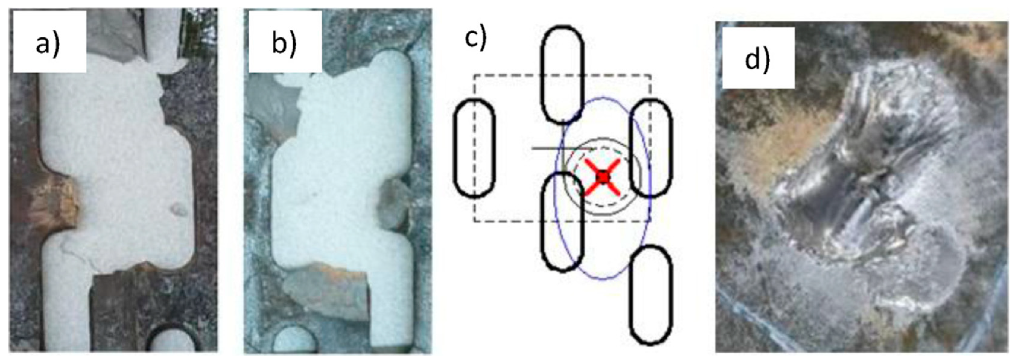
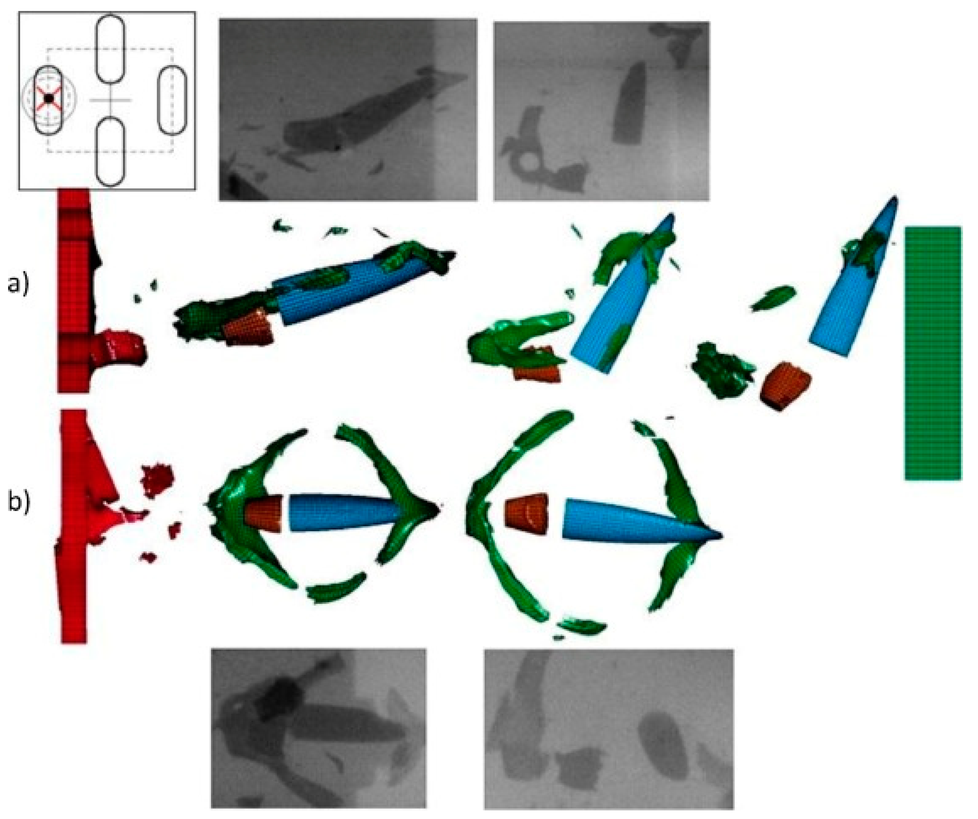
The majority of studies tested circular perforations, which are the most convenient for machining—drilling. However, in the case of an alternative fabrication method, such as waterjet, the perforation shape can easily be altered. In studies by Fras et al. [42,43], slotted-type perforations of 4 mm × 12 mm size were used, Figure 4 and Figure 5. Perforated plates were made of super-bainitic Ultra-High Hardness Perforated Armour Steel Pavise™ (Tata Steel, Mumbai, Maharashtra, India) SBS600P steel, 600–670 BHN, 4 mm thick, while the basic plate was 8 mm MARS 190 400 BHN plate. The projectile was 7.62 mm × 51 mm with a hardened steel core and impact velocity of around 820 m/s. Various impact points were tested and numerically simulated by means of LS-DYNA Johnson–Cook flow and fracture models. The two least convenient impacts were in an area between perforations (Figure 8) and in the center of the perforation (Figure 9). Although less effective compared to edge impact, where intensive core fracture was observed, in these cases, projectile deviation from its initial trajectory is the main defeat mechanism. Even if the tip was not damaged, the side impact did not penetrate the base armour, which is similar to the results obtained with wire meshes, as published in [15].
Kilic et al. [44,45] correlated the finite-element method using LS-Dyna with Lagrange discretization for experimental evaluation of perforated plates. Several penetrating core-defeating mechanisms were identified: asymmetric forces causing the projectile to deviate from incident trajectory (yaw), penetrating core fracture and penetrating core nose erosion. Various cases where the projectile impacts different places of the perforated plates are shown in Figure 10. It can be noted that the most likely impact is shown in Figure 10b. Cases in which the projectile impacts the perforation center and the geometrical center between three perforations result in penetration of the base plate since no lateral forces and stress induction occurs. However, these cases are extremely rare due to a low probability of such impact at this spot and because shooting at exactly 90° to the hull—a perfect defilade shot. These results are confirmed with experimental research, by applying 7.62 mm × 54R mm ammunition, 6 mm perforated plate and 9 mm base plate, 500 BHN hard. It was found that after passing through the perforated plate, the impact into the base plate resulted in an indentation depth of only 1.8 mm, confirming that the base plate thickness could have been considerably lower than the one used. Furthermore, such damage is considerably lower compared to the damage of a single 15 mm 500 BHN armour plate that was used as a reference. There were no traces of sharp intrusion into the base plate, meaning that a yawed impact was present, or the nose of the projectile was eroded or fractured. It can be deduced, that for mass effectiveness reduction, a thinner perforated plate than 6 mm could have been applied, since, in previously presented studies, the 6 mm perforated plate was found to be effective against a much more potent 12.7 mm × 99 mm or 12.7 mm × 108 mm ammunition types, with roughly four times higher kinetic energy. If correlated to the work by Chocron et al. [26], who used 7.62 mm × 51 mm, similar in kinetic energy to 7.62 mm × 54R mm used by Kilic et al. [44,45], it can be deduced that 3–4 mm perforated plate might be sufficient for penetrating core fracture.
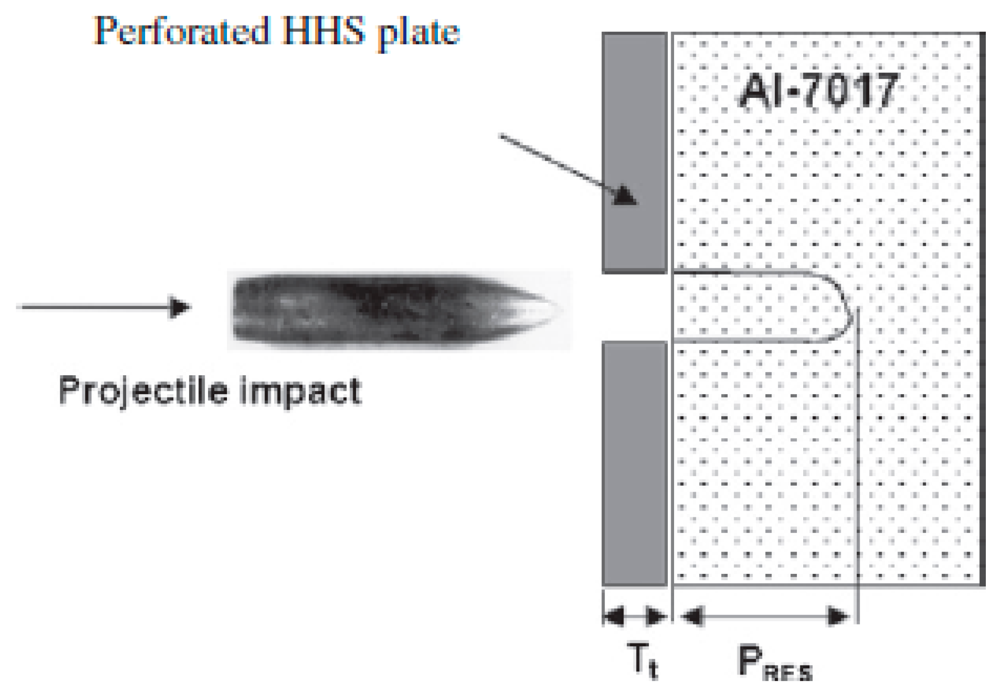
Mishra et al. [46,47] ballistically tested quenched and tempered steels (200–600 °C), along with the perforated plate placed on top of the 7017 aluminium alloy, Figure 11. It was found that the adiabatic shear band (ASB) induced cracking occurs in tested steels tempered at 400 °C or below. In perforated plate steel, however, ASB-induced crack formation can be partially inhibited due to the presence of perforations, (Figure 12 and Figure 13). This makes the perforated plate material more resistant to multiple impacts compared to homogenous steel. Placing the perforated plate on top of the base aluminium alloy (without spacing) has considerable merit since the distance between the base plate and perforated plate inevitably increases the vehicle footprint, which might limit the number of vehicles transported by ships or even limit and prevent the vehicle transportability by certain types of transport aircraft or limit the vehicle to wider streets.
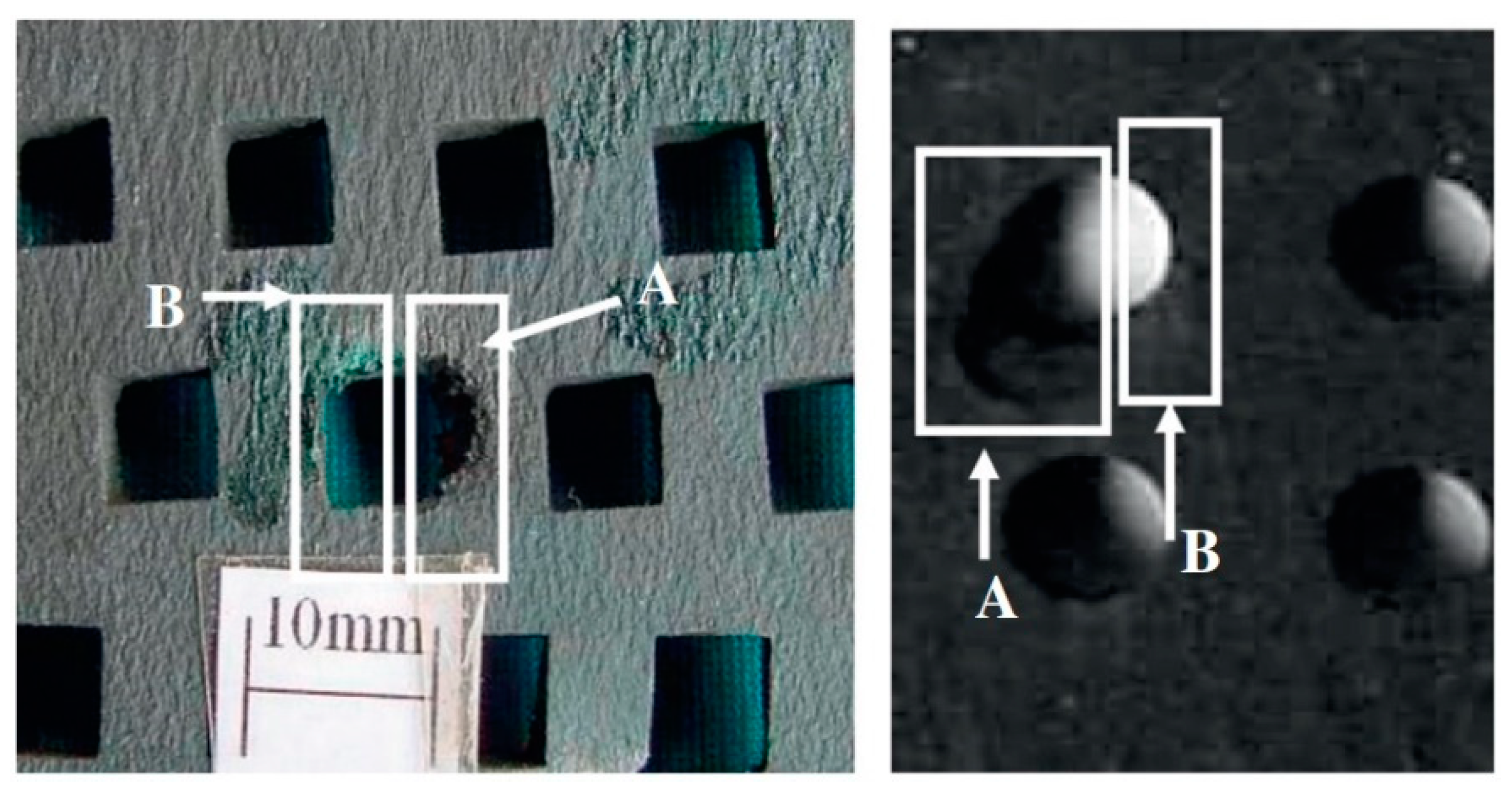
Square and circular perforations were made (2, 4 and 6 mm) into 5 mm heat-treated chromium-nickel steel. The base plate was 60 mm thick and also acted as a witness plate to measure residual penetration, which was used as a measure of mass effectiveness of the perforated plate. It was shown that the highest mass efficiency was achieved by the largest perforations, which were the closest in size to the diameter of 7.62 mm × 51 mm penetrating core used in the test, confirming the results from Radisavljevic et al. [33]. A very important result was that 2 mm perforations did not result in any penetrating core fractures. Very slight differences between perforation sizes existed: 6 mm square shape proved superior compared to 4 mm size, suggesting that the perforation shape should be selected based on the manufacturing method. Interestingly, the damage of perforated plate with square and circular perforations is similar, note white squares in Figure 14. This indicates that stress concentration in the edges of the square perforations does not have a crucial influence on perforated plate damage. Admittedly, in this work, an unusual perforation fabrication method was used, electric discharge machining (EDM) which is both slow and expensive, and therefore, difficult to apply to large-scale industrial manufacturing conditions. It is difficult to compare these results to the results of Balos et al. [37], Radisavljevic et al. [33] and Kilic et al. [44] since the lack of spacing between perforated plates and basic plates might reduce the effectiveness of the armour system. Therefore, it is possible that a 5-mm perforated plate can be essential for achieving a sufficient protection level since the lack of spacing might stabilize the tip of the projectile, prevent its lateral movement and make the fracture of the penetrating core more difficult. This certainly is an attractive field where further work is needed to be done.
Another interesting material that can be applied for perforated plates is the nanostructured bainitic steel published in the work by Burian et al. [48]. This material, having the chemical composition of 0.55C–2.0Mn–1.8Si–1.37Cr–0.7Mo–0.11 V (wt.%); was hot forged and rolled into plates. Subsequently, austenitization was performed, followed by controlled cooling to isothermal transformation at 210 °C for 2 h. This resulted in obtaining the following mechanical properties: Re = 1300 MPa; Rm = 2050 MPa; A = 12%, while the hardness was 640 VHN. The perforated plate 6 mm thick was effective against 7.62 mm × 54R mm B-32 API ammunition with steel core so that a very intensive fragmentation occurred. It was shown that the penetrating core fractured into up to eight fragments, demanding a relatively thin basic plate to completely prevent penetration. At the same time, an excellent correlation between finite element modeling and ballistic testing results was obtained, Figure 15.
The application of amorphous alloy reinforced perforated armor (ARPA) was suggested by Cui et al. [49]. The main advantage of the amorphous component with random atomic arrangement compared to the common crystalline atomic arrangement is a unique combination of mechanical properties. Typically, amorphous metals possess higher specific strength and hardness, that are essential in providing a relatively high resistance of armor materials [50,51,52,53]. However, a lower impact strength is offset by the inherent crack arresting properties of perforated plates. In [49], the effect of various ARPA thicknesses, from 0 to 1.5 mm over the RHA base perforated plate (overall thickness 6 mm) were analyzed. It was found that the increase in ARPA thickness enhances the effectiveness of the perforated plate by increasing the projectile erosion.
An attractive, yet relatively simple use of perforated plates is demonstrated in the work by Chao et al. [54]. Perforated plates with the hardness of 500 BHN, with 4, 5 and 6 mm thicknesses, Ø5 and 6 mm perforations and 10 and 12 mm distance between perforation centers, were tested against 7.62 mm × 54R mm B32 API ammunition. It was shown that when mounted at extreme obliquity of 76°, both perforated plate and homogenous plate can provide projectile ricochet. However, being perforated, the weight of these plates can be significantly reduced. In this study, 26.24% weight reduction was achieved by the application of perforated versus the homogenous plate.

6. Blast Passive Mitigation

Besides kinetic energy ammunition, the highest threat to military vehicles in the last 20 years were shaped charges and IEDs (Improvised Explosive Devices) [10]. The effect of perforated plates versus shaped charges refers to increasing the stand-off distance, as in any other spaced armor, albeit at lower weight since perforations reduce the weight of the armor system. Older-shaped charges were more sensitive to this effect; however, more modern ones cannot be defeated completely. The effect of increasing the stand-off distance is more related to mitigating their effect, that is, the decreasing of the so-called lethal cone. On the other hand, several references explain the mechanisms and the potential of perforated plates in the respect of IED blast mitigation. So far, there were three main aspects of blast mitigation: energy absorption, blast deflection and keeping an adequate distance from detonation point [55]. Langdon et al. [56,57] and Ciortan et al. [58] proposed the application of perforated plates and perforated multilayer structures, respectively. Langdon et al. [56] reported that one deformable mild steel perforated plate, 2 mm thick can reduce deflection of the 1.6 mm reference target plate by 65–75%, while two 2 mm perforated plates of the same type, by 90–95%. Thus, perforated plates proved very effective in mitigating blasts, although large plastic displacement of the perforated plates was observed. On the other hand, in the work done by Ciortan et al. [58], who simulated the effect of 6.5 mm perforated plate, placed at 200 mm distance from the multilayer composite base plate (Kevlar, Aluminium, Armco iron, Aluminium, Kevlar), simulating the base vehicle armor. Interestingly, 6.5 mm thick perforated plates closely correspond to perforated plates effective against 12.7 mm M8 API ammunition, used in experiments by Balos et al. [13,14,19,32,35] and Radisavljevic et al. [33]. It was shown that a perforated plate effectively mitigates the effect of 5 kg TNT which is similar to a typical anti-tank mine.

7. Concluding Remarks

Based on the review presented, the following conclusions can be drawn:
  • Perforated plates work mainly through stress induction in the projectile, causing fractures of the penetrating core of armor-piercing ammunition. Penetrating core fracture occurs as strains above 2%. Besides penetrating core fracture, which is the optimal case, perforated plates work through inducing yaw and penetrating core tip damage and erosion.
  • The perforated plate-based armor system has an exceptional multi-hit resistance due to crack arrest by the nearest perforation. For further crack initiation and propagation, another impact is required in the damaged region. ASB-induced crack formation can be partially inhibited due to the presence of perforations, making the perforated plate material more resistant to multiple impacts compared to homogenous steel.
  • Perforated plates placed directly on the basic armor also induce bend stresses in the penetrating core, but as the projectile tip becomes embedded in the base plate, fracture potential might be reduced, rendering the need to increase the thickness of the perforated plate.
  • Besides heat-treated steels, commercial and armor steels, nanostructured bainitic steels and austempered ductile and compacted graphite irons can be used, essentially enabling a wide variety of materials and fabrication processes to manufacture perforated plates.
  • Considerable potential exists for applying amorphous metals to reinforce the crystalline base structure of the perforated plate, but this remains to be proved experimentally, as only simulations proved its merit. Simulations proved the potential of using high-strength aluminium alloys.
  • If spaced, perforated plates inevitably increase the footprint and weight of the vehicle, which is a major deficiency. However, a perforated plate placed directly on the base plate deserves more attention from the point of view of defeating kinetic energy rounds, while optimizing parasitic weight and volume. A perforated plate placed directly at the base armor will have a negligible effect against shaped charges and IEDs.
  • Even relatively thin perforated plates placed at some distance from the base plate significantly mitigate the effects of a blast from IEDs, providing higher survivability of the vehicle in the contemporary battlefield.

Author Contributions

Conceptualization and writing S.B.; review and editing D.H.; validation and funding acquisition A.B.; investigation, resources and editing D.L.Z. All authors have read and agreed to the published version of the manuscript.

Funding

This research received no external funding.

Institutional Review Board Statement

Not applicable.

Informed Consent Statement

Not applicable.

Data Availability Statement

Not applicable.

Acknowledgments

This research paper has been supported by the Ministry of Education, Science and Technological Development of the Republic of Serbia, through the project no. 451-03-68/2020-14/200156: “Innovative scientific and artistic research from the FTS (activity) domain”. The authors gratefully acknowledge research funding by the project entitled “Modern technologies in materials science and welding technology” on the Department of Production Engineering, Faculty of Technical Sciences Novi Sad, Serbia. Authors are grateful to Jon D. Tirpak, Chief Engineer, Sabattis, LLC, Associate, VSA for technical assistance.

Conflicts of Interest

The authors declare no conflict of interest.

References

  1. Miller, D.; Foss, C. Modern Land Combat; Salamander: London, UK, 1987. [Google Scholar]
  2. Hilmes, R. Brassey’s Multilingual Military Dictionary; Brassey’s Defence Publishers: London, UK, 1987; pp. 71–79. [Google Scholar]
  3. Djordjevic, M. Tenkovi 1945-2005; NIU Vojska: Belgrade, Serbia, 1997. [Google Scholar]
  4. Djordjevic, M. Future Armoured Troop Carrying Vehicles. Odbrana, 76; Arsenal, 23 2009, 9–24. [Google Scholar]
  5. Djordjevic, M.; Arsic, S. Oklopni Transporteri 1945–2005; NIU Vojska: Belgrade, Serbia, 2001. [Google Scholar]
  6. Odanović, Z.; Bobić, B. Ballistic Protection Efficiency of Composite Ceramics/Metal Armours. Sci. Rev. 2003, 53, 30–37. [Google Scholar]
  7. Ogorkiewitz, R. Armor for Light Combat Vehicles–Advances in Armour Materials. Int. Def. Rev. 2002, 35, 41–45. [Google Scholar]
  8. Phelps, W.; Schoeters, R. Panzer Survivors: Panzerkampfwagen IV Ausf. A-J; Masalai Press: Oakland, CA, USA, 2005. [Google Scholar]
  9. Jenz, T.; Doyle, D. Drachtgeflectschuerzen. AFV News 2002, 37, 6–8. [Google Scholar]
  10. Balos, S. Non-Homogenous Spaced Metallic Armour for Armoured Vehicles; University of Novi Sad: Novi Sad, Serbia, 2010. [Google Scholar]
  11. Grove, E. World War II–Tanks; Orbis Publishing: London, UK, 1976. [Google Scholar]
  12. Ogorkiewitz, R. Technology of Tanks; Jane’s Information Group: Coulsdon, Surrey, UK, 1991. [Google Scholar]
  13. Balos, S.; Grabulov, V.; Sidjanin, L.; Pantic, M. Wire Fence as Applique Armour. Mater. Des. 2010, 31, 1293–1301. [Google Scholar] [CrossRef]
  14. Balos, S.; Pecanac, M.; Trivkovic, M.; Sidjanin, L. Ballistic Behavior of Multilayer Wire Mesh Application Armor. Adv. Technol. Mater. 2019, 44, 7–11. [Google Scholar] [CrossRef]
  15. Balos, S. Unpublished Material. Personal Collection. 2009. [Google Scholar]
  16. Ogorkiewitz, R. Advances in Armour Materials. Int. Def. Rev. 1991, 4, 349–352. [Google Scholar]
  17. Radetic, M. Pravci Daljeg Razvoja Borbenih Vozila Pesadije. Vojn. Glas. 2001, 1, 83–100. [Google Scholar] [CrossRef]
  18. Howell, R.A.; Montgomery, J.S.; Van Aken, D.C. Advancements in Steel for Weight Reduction of P900 Armor Plate. Iron Steel Technol. 2009, 6, 168–176. [Google Scholar]
  19. Auyer, R.; Buccellato, R.; Gidynski, A. Perforated Plate Armor. U.S. Patent No. 5,014,593, 14 April 1991. [Google Scholar]
  20. Ogorkiewicz, R.M. Shifting Focus: Armored Vehicle Protection Adapts to New Threats. Janes Int. Def. Rev. 2007, 40, 35–43. [Google Scholar]
  21. Arcelor Mittal MARS 300 brochure. Available online: https://industeel.arcelormittal.com/wp-content/uploads/2018/06/DS-PROTECTION-MARS300-GB.pdf (accessed on 22 February 2021).
  22. Atabaki, M.M.; Nikodinovski, M.; Chenier, P.; Ma, J.; Harooni, M.; Kovacevic, R. Welding of Aluminum Alloys to Steels: An Overview. J. Manuf. Sci. Prod. 2014, 14, 59–78. [Google Scholar] [CrossRef]
  23. Potesser, M.; Schoeberl, T.; Antrekowitsch, H.; Bruckner, J. The Characterization of the Intermetallic Fe-Al Layer of Steel-aluminum Weldings. In Proceedings of the EPD Congress, The Minerals, Metals & Materials Society, San Antonio, TX, USA, 12–16 March 2006; pp. 167–176. [Google Scholar]
  24. Haidara, F.; Record, M.C.; Duployer, B.; Mangelinck, D. Phase Formation in Al-Fe Thin Film Systems. Intermetallics 2012, 23, 143–147. [Google Scholar] [CrossRef]
  25. Bruckner, J. Considering Thermal Processes for Dissimilar Metals–Joining Steel to Aluminum in Heat-intensive Applications. Fabricator, 28 August 2003. [Google Scholar]
  26. Chocron, S.; Anderson, C.E.; Grosch, D.J.; Popelar, C.H. Impact of the 7.62-mm APM2 Projectile against the Edge of a Metallic Target. Int. J. Impact Eng. 2001, 25, 423–437. [Google Scholar] [CrossRef]
  27. Mubashar, A.; Uddin, E.; Anwar, S.; Arif, N.; Waheed Ul Haq, S.; Chowdhury, M.A.K. Ballistic Response of 12.7 mm Armour Piercing Projectile against Perforated Armour Developed from Structural Steel. Proc. Inst. Mech. Eng. Part L J. Mater. Des. Appl. 2019, 233, 1993–2005. [Google Scholar] [CrossRef]
  28. Smallman, R.E.; Bishop, R.J. Modern Physical Metallurgy & Materials Engineering, 6th ed.; Butterworth Heinemann: Woburn, MA, USA, 1999. [Google Scholar]
  29. Agudo, L.; Eyidi, D.; Schmaranzer, C.H.; Arenholz, E.; Jank, N.; Bruckner, J.; Pyzalla, A.R. Intermetallic Fe x Al y-phases in a Steel/Al-alloy Fusion Weld. J. Mater. Sci. 2007, 42, 4205–4214. [Google Scholar] [CrossRef]
  30. Mendez, P.; Eagar, T. New Trends in Welding in the Aeronautic Industry Bilboa, Spain. In Proceedings of the 2nd Conference of New Manufacturing Trends, San Sebastian, Spain, 24–25 May 2000; pp. 1–15. [Google Scholar]
  31. Gullino, A.; Matteis, P.; Aiuto, F.D. Review of Aluminum-to-steel Welding Technologies for Car-body Applications. Metals 2019, 9, 315. [Google Scholar] [CrossRef] [Green Version]
  32. Balos, S.; Grabulov, V.; Sidjanin, L.; Pantic, M.; Radisavljevic, I. Geometry, Mechanical Properties and Mounting of Perforated Plates for Ballistic Application. Mater. Des. 2010, 31, 2916–2924. [Google Scholar] [CrossRef]
  33. Radisavljevic, I.; Balos, S.; Nikacevic, M.; Sidjanin, L. Optimization of Geometrical Characteristics of Perforated Plates. Mater. Des. 2013, 49, 81–89. [Google Scholar] [CrossRef]
  34. Diederen, A.; Broos, J.; Peijen, M. Modern Armour Configurations against 14.5 mm AP. In Lightweight Armour Systems Symposium, Shrivenham, Proceedings of the Lightweight Armour Systems Symposium, Shrivenham, UK, 28–30 June 1995; Royal Military College of Science, Shrivenham: Shrivenham, UK, 2006; paper no. 131193. [Google Scholar]
  35. Balos, S. Perforirane Ploče za Balističku Zaštitu; Faculty of Technical Sciences: Novi Sad, Serbia, 2015. [Google Scholar]
  36. Hazell, P.J.; Roberson, C.J.; Moutinho, M. The Design of Mosaic Armour: The Influence of Tile Size on Ballistic Performance. Mater. Des. 2008, 29, 1497–1503. [Google Scholar] [CrossRef] [Green Version]
  37. Balos, S.; Radisavljevic, I.; Rajnovic, D.; Dramicanin, M.; Tabakovic, S.; Eric-Cekic, O.; Sidjanin, L. Geometry, Mechanical and Ballistic Properties of ADI Material Perforated Plates. Mater. Des. 2015, 83, 66–74. [Google Scholar] [CrossRef]
  38. Balos, S.; Radisavljevic, I.; Rajnovic, D.; Janjatovic, P.; Dramicanin, M.; Eric-Cekic, O.; Sidjanin, L. Ballistic Behaviour of Austempered Compacted Graphite Iron Perforated Plates. Def. Sci. J. 2019, 69, 571–576. [Google Scholar] [CrossRef] [Green Version]
  39. Balos, S.; Sidjanin, L.; Rajnovic, D. ADI Materials for Ballistic Protection. In Proceedings of the 34th International Conference on Production Engineering, Nis, Serbia, 28–30 September 2011; pp. 91–94. [Google Scholar]
  40. Thomas, D.J. Laser Cut Hole Matrices in Novel Armour Plate Steel for Appliqué Battlefield Vehicle Protection. Def. Technol. 2016, 12, 351–359. [Google Scholar] [CrossRef] [Green Version]
  41. Balos, S.; Sidjanin, L. Metallographic Study of Non-homogenous Armour Impacted by Armour-piercing Incendiary Ammunition. Mater. Des. 2011, 32, 4022–4029. [Google Scholar] [CrossRef]
  42. Fras, T.; Faderl, N. Influence of Add-On Perforated Plates on the Protective Performance of Light-Weight Armour Systems. Probl. Mechatron. Armament Aviat. Saf. Eng. 2018, 9, 31–48. [Google Scholar] [CrossRef]
  43. Fras, T.; Murzyn, A.; Pawlowski, P. Defeat Mechanisms Provided by Slotted Add-on Bainitic Plates against Small-calibre 7.62 mm × 51 AP Projectiles. Int. J. Impact Eng. 2017, 103, 241–253. [Google Scholar] [CrossRef]
  44. Kiliç, N.; Bedir, S.; Erdik, A.; Ekici, B.; Taşdemirci, A.; Güden, M. Ballistic Behavior of High Hardness Perforated Armor Plates against 7.62mm Armor Piercing Projectile. Mater. Des. 2014, 63, 427–438. [Google Scholar] [CrossRef] [Green Version]
  45. Kılıç, N.; Ekici, B.; Bedir, S. Optimization of High Hardness Perforated Steel Armor Plates using Finite Element and Response Surface Methods. Mech. Adv. Mater. Struct. 2017, 24, 615–624. [Google Scholar] [CrossRef]
  46. Mishra, B.; Jena, P.K.; Ramakrishna, B.; Madhu, V.; Bhat, T.B.; Gupta, N.K. Effect of Tempering Temperature, Plate Thickness and Presence of Holes on Ballistic Impact Behavior and ASB Formation of a High Strength Steel. Int. J. Impact Eng. 2012, 44, 17–28. [Google Scholar] [CrossRef]
  47. Mishra, B.; Ramakrishna, B.; Jena, P.K.; Siva Kumar, K.; Madhu, V.; Gupta, N.K. Experimental Studies on the Effect of Size and Shape of Holes on Damage and Microstructure of High Hardness Armour Steel Plates under Ballistic Impact. Mater. Des. 2013, 43, 17–24. [Google Scholar] [CrossRef]
  48. Burian, W.; Żochowski, P.; Gmitrzuk, M.; Marcisz, J.; Starczewski, L.; Juszczyk, B.; Magier, M. Protection Effectiveness of Perforated Plates Made of High Strength Steel. Int. J. Impact Eng. 2019, 126, 27–39. [Google Scholar] [CrossRef]
  49. Cui, T.; Qin, Q.; Yan, W.; Wang, T.; Zhang, J. Ballistic Resistance of Novel Amorphous-Alloy-Reinforced Perforated Armor. Acta Mech. Solida Sin. 2021, 34, 12–26. [Google Scholar] [CrossRef]
  50. Wang, W.; Dong, C.; Shek, C. Bulk Metallic Glasses. Mater. Sci. Eng. R Rep. 2004, 44, 45–89. [Google Scholar] [CrossRef]
  51. Schuh, C.A.; Hufnagel, T.C.; Ramamurty, U. Mechanical Behavior of Amorphous Alloys. Acta Mater. 2007, 55, 4067–4109. [Google Scholar] [CrossRef]
  52. Dai, L.H.; Bai, Y.L. Basic Mechanical Behaviors and Mechanics of Shear Banding in BMGs. Int. J. Impact Eng. 2008, 35, 704–716. [Google Scholar] [CrossRef] [Green Version]
  53. Johnson, W.L. Bulk Glass-forming Metallic Alloys: Science and Technology. MRS Bull. 1999, 24, 42–56. [Google Scholar] [CrossRef]
  54. Chao, L.; Kun, L.; Guo, X.J.; Yuan, L.X. Experimental Study on Ballistic Performance for Multi-hole Armor Steel Plates Against the 7.62mm Armor Piercing Projectile. IOP Conf. Ser. Mater. Sci. Eng. 2018, 382. [Google Scholar] [CrossRef] [Green Version]
  55. Madhu, V.; Bhat, T.B. Armour Protection and Affordable Protection for Futuristic Combat Vehicles. Def. Sci. J. 2011, 61, 394–402. [Google Scholar] [CrossRef] [Green Version]
  56. Langdon, G.S.; Nurick, G.N.; Balden, V.H.; Timmis, R.B. Perforated Plates as Passive Mitigation Systems. Def. Sci. J. 2008, 58, 238–247. [Google Scholar] [CrossRef] [Green Version]
  57. Langdon, G.; Nurick, G.; Du Plessis, N.; Rossiter, I. Using Perforated Plates as a Blast Wave Shielding Technique for Application to Tunnels. Appl. Mech. Mater. 2011, 82, 467–472. [Google Scholar] [CrossRef]
  58. Ciortan, I.F.; Giurgiu, I.T.; Pupəža, C. Passive Mitigation Solutions using Explicit Dynamics Simulation. Proc. Rom. Acad. Ser. A Math. Phys. Tech. Sci. Inf. Sci. 2014, 15, 262–271. [Google Scholar]
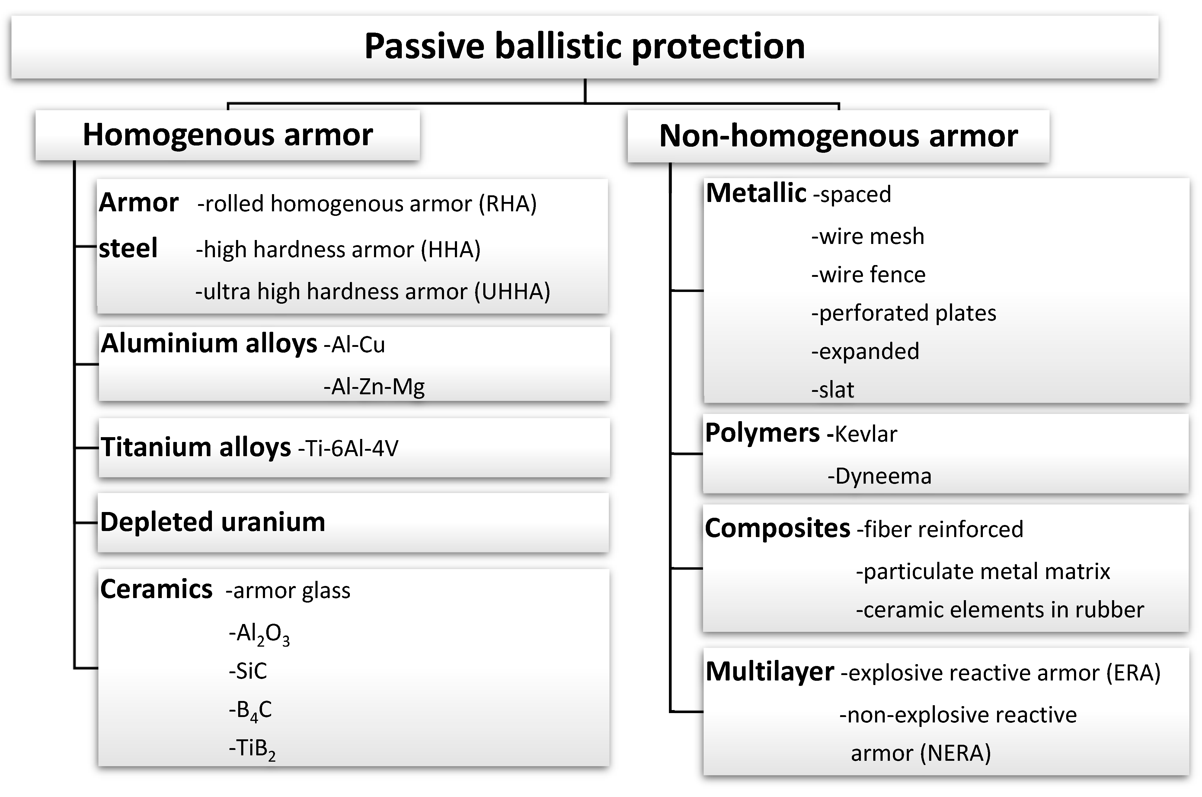
Figure 1. Passive armour materials and types.
Metals 11 00526 g001
Figure 2. Patented wires in a zig-zagged configuration useful in causing projectile yaw. Zig-zag configuration of patented wires is indicated by a broken black line [15].
Metals 11 00526 g002
Figure 3. A simulation conducted by Chocron et al. [26]: (a) initial configuration; (b) 12 µs after impact showing bending and stress contours. Reprinted with permission from Elsevier: Int. J. Impact Eng., Copyright 2021, License: 5017580939892.
Metals 11 00526 g003
Figure 4. Maximum strain in the projectile core versus target thickness [26]. Reprinted with permission from Elsevier: Int. J. Impact Eng., Copyright 2021, License: 5032390676694.
Metals 11 00526 g004
Figure 5. Perforated plate damage (a); base plate with two dents on the base plate (b) [15].
Metals 11 00526 g005
Figure 6. Test setup with the austempered ductile iron (ADI) material perforated plate made of nine smaller perforated plates joined by bolts [37]. Reprinted with permission from Elsevier: Mater. Des., Copyright 2021, License: 5027070247748.
Metals 11 00526 g006
Figure 7. Damage on the back of the perforated plate: (a) ADI-275; (b) ADI-400 [37]. Reprinted with permission from Elsevier: Mater. Des., Copyright 2021, License: 5027070247748.
Metals 11 00526 g007
Figure 8. Damage of the perforated plate after the impact in an area between perforations: (a) front side; (b) rear side; (c) schematic view of the damaged area; (d) deformation of the base armour [43]. Reprinted with permission from Elsevier: Int. J. Impact Eng., Copyright 2021, License: 5017590451474.
Metals 11 00526 g008
Figure 9. Numerical results of the AP impact in the center of the perforation compared with the flash X-ray images: (a) bottom view; (b) side view [43]. Reprinted with permission from Elsevier: Int. J. Impact Eng., Copyright 2021, License: 5017590451474.
Metals 11 00526 g009
Figure 10. Projectile impacts in the perforated plate: (a) center of the hole; (b) hole side; (c) between two holes; (d) geometric center between three holes [44]. Reprinted with permission from Elsevier: Mater. Des., Copyright 2021, License: 5017590846392.
Metals 11 00526 g010
Figure 11. Target configuration studied in [47]. Reprinted with permission from Elsevier: Mater. Des., Copyright 2021, License: 5027070526474.
Metals 11 00526 g011
Figure 12. Micrograph of the through thickness of (HHS + Al-alloy; HHS-High Hardness Steel configuration (a) front HHS steel plate (b) backing Al-alloy plate. The arrow shows the direction of the projectile [47]. Reprinted with permission from Elsevier: Mater. Des., Copyright 2021, License: 5017591074019.
Metals 11 00526 g012
Figure 13. Micrograph of through thickness region of (PHHS + Al-alloy; PHHS-Perforated High Hardness Steel) configuration having 6 mm square holes (a) side A of front PHHS plate, (b) side B of front PHHS plate and (c) backing Al-alloy plate. The arrow shows the direction of the projectile. [47]. Reprinted with permission from Elsevier: Mater. Des., Copyright 2021, License: 5017591074019.
Metals 11 00526 g013
Figure 14. 6 mm square and circular perforation damage: area A is the deformed and area B is the non-deformed region of a similar morphology [47]. Reprinted with permission from Elsevier: Mater. Des., Copyright 2021, License: 5027070526474.
Metals 11 00526 g014
Figure 15. Comparison of the projectile fragmentation obtained experimentally and in the simulations with the use of principal stress/strain failure criterion applied for the hardened steel cores [48]. Reprinted with permission from Elsevier: Int. J. Impact Eng., Copyright 2021, License: 5017591423106.
Metals 11 00526 g015
Table 1. Typical thicknesses, areal densities and mass effectiveness of various types of armour [7].
Thickness [mm]Areal Density [kg/m2]Mass Effectiveness
380 BHN* rolled homogenous armour (RHA)413221.00
500 BHN* high hardness armour (HHA)362831.14
Aluminium alloy 50831343560.90
Aluminium alloy 7019972701.19
Aluminium alloy 7039912531.27
Titanium alloy Ti-6Al-4V451991.62
500 BHN* HHA and aluminium alloy 5083
500 BHN* HHA and titanium alloy Ti-6Al-4V
-192
167
1.68
1.93
High hardness perforated plates and aluminium alloy 5083-1681.92
Al2O3 ceramics and 500 BHN* HHA
Al2O3 ceramics and aluminium alloy5083
Al2O3 ceramic composite reinforced with glass fibers
-152
146
141
2.12
2.19
2.28
* BHN—Brinell Hardness Number.
Table 2. Geometry, the average number of interconnected perforations, damaged area, areal density and mass effectiveness of various successful perforated plates [10,35,37,38].
Performances Perforated Plate Material
50CrV4H9-6-0H10-6-0H11-6-0ADI-275ACGI-275
Thickness [mm]666677
Perforation diameter [mm]9910111111
Ligament length [mm]4.54.53.53.53.53.5
Inclination [o]2000000
Maximal number of fractured parts253633
Average no. of interconnected perforations66.46.25.87.27.8
Damaged area [mm2]44848348755120762214
Perforated plate areal density [kg/m2]302824232424
Armour system areal density (perforated + base plate) [kg/m2]132130126125126126
Mass effectiveness of the perforated plate vs. 380 BHN RHA3.934.214.925.134.924.92
Mass effectiveness of armour system vs. 380 BHN RHA1.671.691.751.761.751.75
Mechanical properties of perforated plate materials are: 50CrV4: Rp0.2% = 1410 MPa; Rm = 1470 MPa; A = 6%. H: Rp0.2% = 1255 MPa; Rm = 1140 MPa; A = 11%. ADI-275: Rm = 1472 MPa; A = 1%. ACGI-275: Rp0.2% = 1310 MPa; Rm = 1364 MPa; A = 1%.
Publisher’s Note: MDPI stays neutral with regard to jurisdictional claims in published maps and institutional affiliations.