
Effect of Mo Element on the Mechanical Properties and Tribological Responses of CoCrFeNiMox High-Entropy Alloys


 and
and
Abstract
1. Introduction
2. Materials and Methods
3. Results
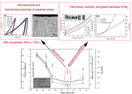
3.1. Microstructure
3.2. Nanoindentation Results
3.3. Mechanical Properties of Fabricated Mox
3.4. Tribological Behavior
3.5. Surface Profilometry
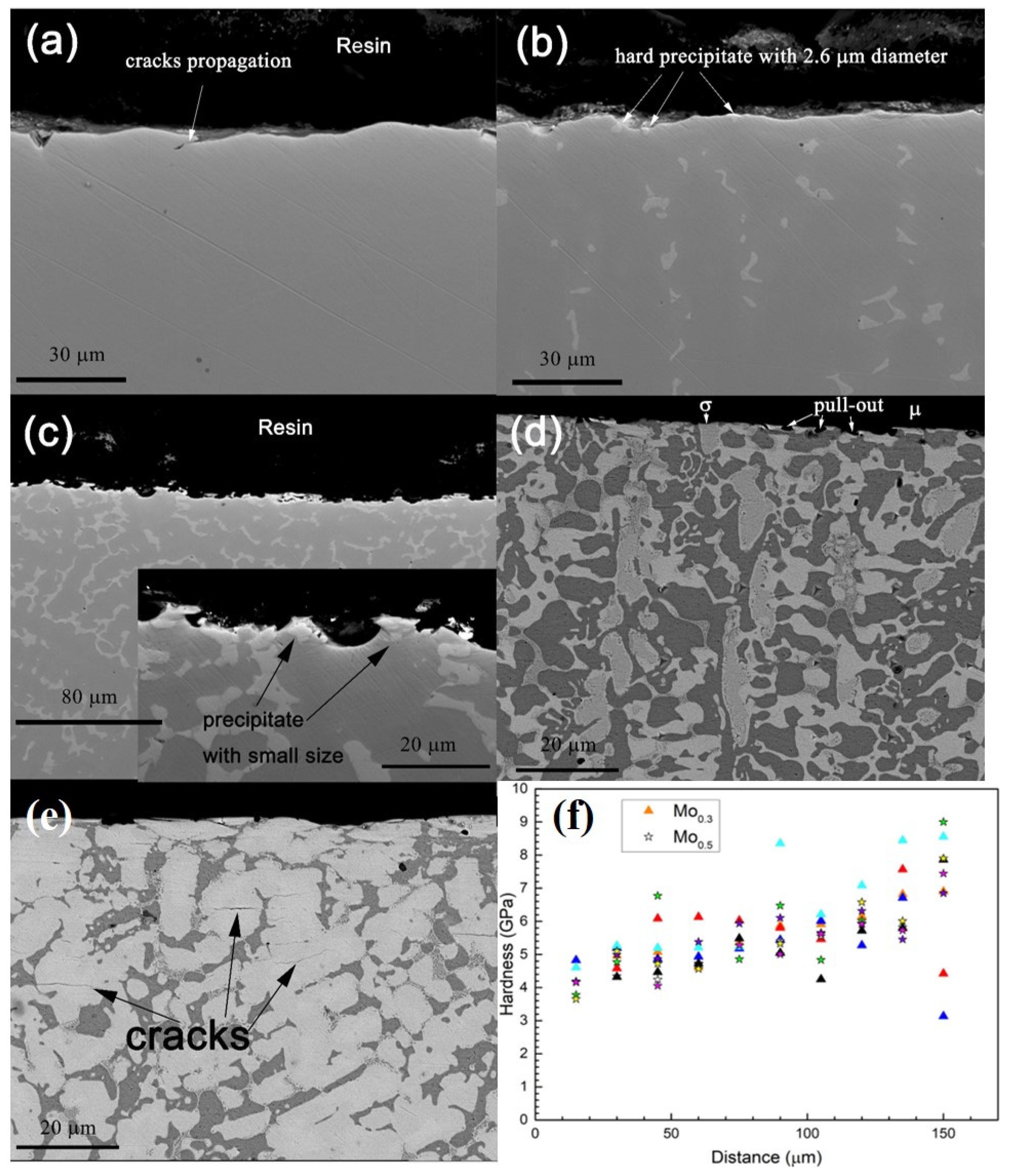
3.6. Subsurface Characterization
4. Discussion
5. Conclusions
Author Contributions
Funding
Institutional Review Board Statement
Informed Consent Statement
Data Availability Statement
Conflicts of Interest
Abbreviations
| HEAs | High entropy alloys |
| FCC | Face centered cubic |
| XRD | X-ray diffraction |
| SEM | Scanning electron microscope |
| EDS | Energy diffraction spectrum |
| TCP | topologically close-packed phases |
References
- Yeh, J.W.; Chen, S.K.; Lin, S.J.; Gan, J.Y.; Chin, T.S.; Shun, T.T.; Tsau, C.H.; Chang, S.Y. Nanostructured High-Entropy Alloys with Multiple Principal Elements: Novel Alloy Design Concepts and Outcomes. Adv. Eng. Mater. 2004, 6, 299–303. [Google Scholar] [CrossRef]
- Cantor, B.; Chang, I.T.H.; Knight, P.; Vincent, A.J.B. Microstructural development in equiatomic multicomponent alloys. Mater. Sci. Eng. A 2004, 375–377, 213–218. [Google Scholar] [CrossRef]
- Tong, C.J.; Chen, M.R.; Yeh, J.W.; Lin, S.J.; Chen, S.K.; Shun, T.T.; Chang, S.Y. Mechanical performance of the AlxCoCrCuFeNi high-entropy alloy system with multi-principal elements. Metall. Mater. Trans. A 2005, 36, 1263–1271. [Google Scholar] [CrossRef]
- Sun, S.J.; Tian, Y.Z.; Lin, H.R.; Lu, S.; Yang, H.J.; Zhang, Z.F. Modulating the prestrain history to optimize strength and ductility in CoCrFeMnNi high-entropy alloy. Scr. Mater. 2019, 163, 111–115. [Google Scholar] [CrossRef]
- Sun, S.J.; Tian, Y.Z.; Lin, H.R.; Yang, H.J.; Dong, X.G.; Wang, Y.H.; Zhang, Z.F. Achieving high ductility in the 1.7 GPa grade CoCrFeMnNi high-entropy alloy at 77 K. Mater. Sci. Eng. A 2019, 740–741, 336–341. [Google Scholar] [CrossRef]
- Chuang, M.H.; Tsai, M.H.; Wang, W.R.; Lin, S.J.; Yeh, J.W. Microstructure and wear behavior of AlxCo1.5CrFeNi1.5Tiy high-entropy alloys. Acta Mater. 2011, 59, 6308–6317. [Google Scholar] [CrossRef]
- Dai, C.D.; Zhao, T.L.; Du, C.W.; Liu, Z.Y.; Zhang, D.W. Effect of molybdenum content on the microstructure and corrosion behavior of FeCoCrNiMox high-entropy alloys. J. Mater. Sci. Technol. 2020, 46, 64–73. [Google Scholar] [CrossRef]
- Ding, Q.; Zhang, Y.; Chen, X.; Fu, X.; Chen, D.; Chen, S.; Gu, L.; Wei, F.; Bei, H.; Gao, Y.; et al. Tuning element distribution, structure and properties by composition in high-entropy alloys. Nature 2019, 574, 223–227. [Google Scholar] [CrossRef] [PubMed]
- Wu, Z.; Bei, H.; Pharr, G.M.; George, E.P. Temperature dependence of the mechanical properties of equiatomic solid solution alloys with face-centered cubic crystal structures. Acta Mater. 2014, 81, 428–441. [Google Scholar] [CrossRef]
- Gludovatz, B.; Hohenwarter, A.; Catoor, D.; Chang, E.H.; George, E.P.; Ritchie, R.O. A fracture-resistant high-entropy alloy for cryogenic applications. Science 2014, 345, 1153–1158. [Google Scholar] [CrossRef] [PubMed]
- Liu, W.H.; Lu, Z.P.; He, J.Y.; Luan, J.H.; Wang, Z.J.; Liu, B.; Liu, Y.; Chen, M.W.; Liu, C.T. Ductile CoCrFeNiMox high entropy alloys strengthened by hard intermetallic phases. Acta Mater. 2016, 116, 332–342. [Google Scholar] [CrossRef]
- Zhu, J.M.; Fu, H.M.; Zhang, H.F.; Wang, A.M.; Li, H.; Hu, Z.Q. Microstructures and compressive properties of multicomponent AlCoCrFeNiMox alloys. Mater. Sci. Eng. A 2010, 527, 6975–6979. [Google Scholar] [CrossRef]
- Miao, J.; Guo, T.; Ren, J.; Zhang, A.; Su, B.; Meng, J. Optimization of mechanical and tribological properties of FCC CrCoNi multi-principal element alloy with Mo addition. Vacuum 2018, 149, 324–330. [Google Scholar] [CrossRef]
- Shun, T.T.; Chang, L.Y.; Shiu, M.H. Microstructure and mechanical properties of multiprincipal component CoCrFeNiMox alloys. Mater. Charact. 2012, 70, 63–67. [Google Scholar] [CrossRef]
- Lyu, Z.; Lee, C.; Wang, S.Y.; Fan, X.; Yeh, J.W.; Liaw, P.K. Effects of constituent elements and fabrication methods on mechanical behavior of high-entropy alloys: A review. Metall. Mater. Trans. A 2019, 50, 1–28. [Google Scholar] [CrossRef]
- Li, W.P.; Wang, X.G.; Liu, B.; Fang, Q.H.; Jiang, C. Fracture mechanisms of a Mo alloyed CoCrFeNi high entropy alloy: In-situ SEM investigation. Mater. Sci. Eng. A 2018, 723, 79–88. [Google Scholar] [CrossRef]
- Niu, Z.Z.; Wang, Y.Z.; Geng, C.; Xu, J.; Wang, Y. Microstructural evolution, mechanical and corrosion behaviors of as-annealed CoCrFeNiMox (x = 0, 0.2, 0.5, 0.8, 1) high entropy alloys. J. Alloys Compd. 2020, 820, 153273. [Google Scholar] [CrossRef]
- Bae, J.W.; Park, J.M.; Moon, J.; Choi, W.M.; Lee, B.J.; Kim, H.S. Effect of μ-precipitates on the microstructure and mechanical properties of non-equiatomic CoCrFeNiMo medium-entropy alloys. J. Alloys Compd. 2019, 781, 75–83. [Google Scholar] [CrossRef]
- Deng, G.; Tieu, A.K.; Su, L.; Wang, P.; Wang, L.; Lan, X.; Cui, S.; Zhu, H. Investigation into reciprocating dry sliding friction and wear properties of bulk CoCrFeNiMo high entropy alloys fabricated by spark plasma sintering and subsequent cold rolling processes: Role of Mo element concentration. Wear 2020, 460–461, 203440. [Google Scholar] [CrossRef]
- Shun, T.T.; Hung, C.H.; Lee, C.F. The effects of secondary elemental Mo or Ti addition in Al0.3CoCrFeNi high-entropy alloy on age hardening at 700°C. J. Alloys Compd. 2010, 495, 55–58. [Google Scholar] [CrossRef]
- Gengxiang, H.; Xun, C.; Yonghua, R. Fundamentals of Materials Science; Shanghai Jiao Tong University Press: Shanghai, China, 2000. [Google Scholar]
- Archard, J.; Hirst, W. The wear of metals under unlubricated conditions. Math. Phys. Sci. 1956, 236, 397–410. [Google Scholar]
- Deng, G.; Tieu, A.K.; Lan, X.; Su, L.; Wang, L.; Zhu, Q.; Zhu, H. Effects of normal load and velocity on the dry sliding tribological behaviour of CoCrFeNiMo0.2 high entropy alloy. Tribol. Int. 2020, 144, 106116. [Google Scholar] [CrossRef]
- Wen, S.; Huang, P. Tribology Principle; Tsinghua University Press: Beijing, China, 2002. [Google Scholar]
- Suh, P.N. The delamination theory of wear. Wear 1973, 25, 111–124. [Google Scholar] [CrossRef]
- Stachowiak, G.; Batchelor, A.W. Engineering Tribology; Butterworth-Heinemann: Oxford, UK, 2013. [Google Scholar]
- Pauschitz, A.; Roy, M.; Franek, F. Mechanisms of sliding wear of metals and alloys at elevated temperatures. Tribol. Int. 2008, 41, 584–602. [Google Scholar] [CrossRef]
- Huttunen-Saarivirta, E.; Kilpi, L.; Hakala, T.J.; Metsäjoki, J.; Ronkainen, H. Insights into the behaviour of tool steel-aluminium alloy tribopair at different temperatures. Tribol. Int. 2018, 119, 567–584. [Google Scholar] [CrossRef]
- Gengxiang, H.; Xun, C.; Yonghua, R. Fundamentals of Materials Science, 2nd ed.; Shanghai Jiaotong University Press: Shanghai, China, 2006. [Google Scholar]
- Zheng, B.; Li, W.; Tu, X.; Song, S.; Huang, W. Effect of ZTA ceramic particles strengthened high chromium white cast iron on three-body abrasion behavior. Mater. Res. Exp. 2019, 6, 116581. [Google Scholar] [CrossRef]
- Holz, D.; Janssen, R.; Friedrich, K.; Claussen, N. Abrasive wear of ceramic-matrix composites. J. Eur. Ceram. Soc. 1989, 5, 229–232. [Google Scholar] [CrossRef]
- Tabor, D. The physical meaning of indentation and scratch hardness. Br. J. Appl. Phys. 1956, 7, 159–166. [Google Scholar] [CrossRef]
- Bowden, F.P.; Moore, A.J.W.; Tabor, D. The Ploughing and Adhesion of Sliding Metals. J. Appl. Phys. 1943, 14, 80–91. [Google Scholar] [CrossRef]


| HEAs | Analyzed Area | Normalized Atomic Molar Ratio by Dividing the Fe Atoms | ||||
|---|---|---|---|---|---|---|
| Fe | Co | Cr | Ni | Mo | ||
| Mo0 | FCC solid solution | 1 | 1.01 | 0.99 | 1.04 | 0 |
| Mo0.3 | FCC solid solution | 1 | 0.99 | 0.88 | 1 | 0.31 |
| σ | 1 | 1.08 | 1.49 | 0.83 | 1.42 | |
| Mo0.5 | FCC solid solution | 1 | 0.98 | 0.84 | 1.09 | 0.47 |
| σ | 1 | 1.04 | 1.34 | 0.89 | 1.59 | |
| Mo1 | FCC solid solution | 1 | 1.05 | 0.85 | 1.16 | 0.8 |
| σ | 1 | 1.07 | 1.16 | 0.93 | 1.64 | |
| μ | 1 | 1.12 | 1.12 | 0.95 | 1.94 | |
| Mo1.5 | FCC solid solution | 1 | 0.96 | 0.79 | 1.19 | 0.96 |
| σ | 1 | 1.05 | 1.01 | 0.96 | 2.28 | |
| μ | 1 | 1.0 | 1.12 | 0.88 | 2.56 | |
| Phase | Lattice Parameters | Crystallite Size | ||
|---|---|---|---|---|
| σ phase | a = 9.165 Å | c = 4.739 Å | c/a = 0.517 Å | 16–33 µm |
| μ phase | a = 4.757 Å | c = 25.589 Å | c/a = 5.379 Å | 29–81 µm |
| Materials | Hardness (GPa) |
|---|---|
| YG6 ball | 20 ± 0.5 |
| Mo0 FCC solid solution | 3.8 ± 0.1 |
| FCC solid solution for Mo0.3, Mo0.5, and Mo1.5 | 4.7 ± 0.2 |
| σ phase | 21 ± 1.2 |
| µ phase | 21 ± 1.7 |
Publisher’s Note: MDPI stays neutral with regard to jurisdictional claims in published maps and institutional affiliations. |
© 2021 by the authors. Licensee MDPI, Basel, Switzerland. This article is an open access article distributed under the terms and conditions of the Creative Commons Attribution (CC BY) license (http://creativecommons.org/licenses/by/4.0/).
Share and Cite
Liu, Y.; Xie, Y.; Cui, S.; Yi, Y.; Xing, X.; Wang, X.; Li, W. Effect of Mo Element on the Mechanical Properties and Tribological Responses of CoCrFeNiMox High-Entropy Alloys. Metals 2021, 11, 486. https://doi.org/10.3390/met11030486
Liu Y, Xie Y, Cui S, Yi Y, Xing X, Wang X, Li W. Effect of Mo Element on the Mechanical Properties and Tribological Responses of CoCrFeNiMox High-Entropy Alloys. Metals. 2021; 11(3):486. https://doi.org/10.3390/met11030486
Chicago/Turabian StyleLiu, Ying, Yongxin Xie, Shaogang Cui, Yanliang Yi, Xuewei Xing, Xiaojian Wang, and Wei Li. 2021. "Effect of Mo Element on the Mechanical Properties and Tribological Responses of CoCrFeNiMox High-Entropy Alloys" Metals 11, no. 3: 486. https://doi.org/10.3390/met11030486
APA StyleLiu, Y., Xie, Y., Cui, S., Yi, Y., Xing, X., Wang, X., & Li, W. (2021). Effect of Mo Element on the Mechanical Properties and Tribological Responses of CoCrFeNiMox High-Entropy Alloys. Metals, 11(3), 486. https://doi.org/10.3390/met11030486