Article

Achieving Accuracy Improvements for Single-Point Incremental Forming Process Using a Circumferential Hammering Tool

Department of Manufacturing Engineering, Transilvania University of Brasov, B-dul Eroilor 29, 500036 Brasov, Romania
*
Author to whom correspondence should be addressed.
Metals 2021, 11(3), 482; https://doi.org/10.3390/met11030482
Submission received: 14 February 2021 / Revised: 9 March 2021 / Accepted: 12 March 2021 / Published: 14 March 2021

Abstract

:
The paper presents a novel solution for improving the accuracy of the wall area of parts manufactured by single point incremental forming. Thus, a forming tool with a special design that works according to the principle of circumferential hammering is deployed, with a direct improving effect of the forming conditions and consequently of the dimensional accuracy of the part. The research is focused on an experimental study of frustum-of-cone shapes manufactured from sheet metal blanks of DC05 deep drawing steel of 1 mm thickness. A typical customary technological setup is used for the single point incremental forming process, without any additional elements, and two forming tools, a hemispherical and a special one, which use the circumferential hammering effect. Several preliminary tests using both tools were performed in order to prove that part accuracy can be significantly improved by using the circumferential hammering tool. The research was further expanded to investigate the influence on part wall dimensional accuracy of three factors: tool spindle speed, tool feed rate and part dimensional configuration. Using a full factorial plan of experiments the results of 32 test runs were processed. All parts were machined adequately, free of any material fracturing. Based on the achieved machining accuracy of the part walls, precision mathematical models were developed for the prediction of part dimensional accuracy in those areas. The mathematical models were validated by practice, as the predicted accuracies were matched by the experimental results.

1. Introduction

Single-point incremental forming (SPIF) is a very flexible forming process of sheet metal that does not require, for its implementation, a dedicated set of tools as is necessary in conventional processes [1]. Through this process, a wide range of concave or hollow sheet metal parts can be manufactured using the following technological setup: a sheet clamping device, a simple forming tool and a minimum a three-axis computer numerical control (CNC) milling machine [2].
While SPIF has been successfully implemented in many applications from different industries, the dimensional accuracy of the parts remained lower than accuracy achievable through conventional forming processes. Thus, improvement of geometric accuracy is one of the challenges faced by research and process development in industrial companies. Li et al. [3] claim, following other studies, that most of the industrial applications for sheet metal parts generally require a geometric accuracy of ±0.2 mm, while the dimensional precision obtained for parts manufactured by incremental sheet forming (ISF) is generally around ±3 mm. Other studies state that most industrial applications impose a dimensional accuracy of less than ±1 mm, sometimes less than ±0.5 mm for a significant number of parts categories, while the tolerances obtained in parts manufactured by incremental forming is around ±1.5 mm for axis-symmetrical and ±2 mm for asymmetrical parts [4]. Thus, regardless of the magnitude of fluctuations of ISF part tolerances in different applications, at present a major shortcoming of incremental forming processes is the poor dimensional accuracy, which prevents their further popularization and industrial implementation by product manufacturers [3,5]. Hence ISF part accuracy is one of the hottest research topics in the field of incremental forming [3].
The geometric inaccuracies occurring in SPIF processes are mainly caused by three main types of errors (Figure 1) agreed upon by most of the research groups in this field [6,7,8]:
-
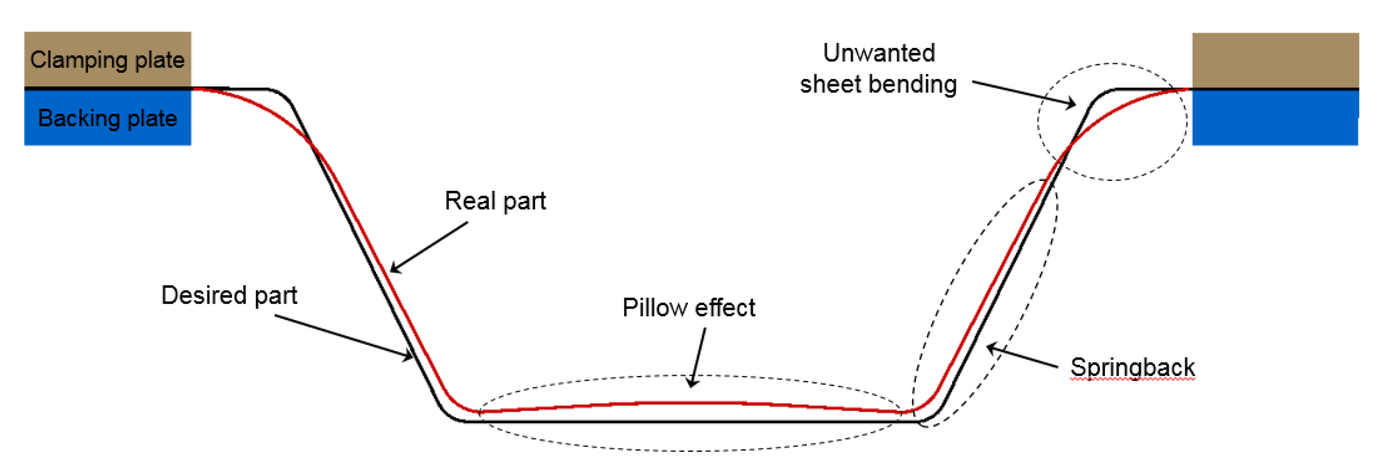
unwanted sheet bending over the clamping device backing plate, in the upper corner radius area, next close to the major base of the part;
-
springback effect—an elastic phenomenon that occurs in almost all cave sheet metal parts [9];
-
pillow effect—a concave surface occurring on bottom of the part, which is an undeformed area.
In the literature numerous solutions can be found, designed to improve, in different ways, process performance and part accuracy. The geometric deviations caused by unwanted sheet bending over the backing plate edge and by the pillow effect are much easier to overcome than geometric deviations caused by springback. Essa and Hartley [10] present two efficient solutions to reduce such geometric deviations. A plate is used to support the sheet flange next to the major base of the part shape, thus reducing deviation caused by unwanted sheet bending in this area. The second solution put forward to compensate the pillow effect entails extending the forming toolpath to the bottom area of the part.
The geometric deviations of the tapered walls are more difficult to address, because in those areas part inaccuracy is due mainly to springback. Thus, reducing the springback effect is one of the major concerns in SPIF research; further on several process-related solutions are discussed, implemented in the last years.
Maqbool and Bambach [11] studied the influence of SPIF process parameters upon final part accuracy. They assert that a better geometric accuracy can be obtained if the parts are machined by small diameter tools and with a small incremental step depth. However, two obvious disadvantages are highlighted: a small diameter decreases tool rigidity, thus decreasing also part precision, and a small step depth significantly increases part manufacturing time.
Nowadays, double-pass or multiple-pass forming are common strategies proved to be useful in improving part dimensional accuracy in incremental forming. For instance, Dai et al. [12] implemented a multipass strategy to deform non-axisymmetric parts manufactured from aluminum alloy and compared to single pass forming, they succeeded to improve part accuracy by more than 60%. CAM software systems offer multiple solutions similar to those used in milling that can be successfully implemented also for the toolpath in SPIF processes. Literature features various solutions of two or multiple stage toolpaths that can be implemented for different part shapes [7,13]. The inconvenience in using two or multiple forming paths is that, usually, from one stage to another part deviations should be measured in order to be compensated in the next forming stage. This makes the process more difficult to implement, due to increased process complexity and part manufacturing time and costs.
A significant improvement in terms of part accuracy was brought by using local or global material heating methods. By heating the sheet metal blank, material ductility is improved and springback deviations are reduced. As an example, Duflou et al. [14] used dynamic local heating of the sheet material by means of a laser beam applied to the contact zone simultaneously with the forming tool, on the opposite side of the part. Multiple other material heating methods were used over time, with positive results on the part dimensional accuracy, as follows [15]: friction heating a high tool rotational speed of the tool [16], electric heating [17], induction heating [18], warming sheet material by using hot air blowers [19] or hot fluids [20], using a furnace [21] or even combinations of the above methods [22]. Although the improvements due to local or global material heating are confirmed, such methods require auxiliary heating equipment that can be expensive and difficult to handle, and more importantly entail significant energy consumption during forming. Another disadvantage of material heating methods, even when deploying friction heating by high tool rotational speed, is the significant worsening of the mechanical properties (yield strength and tensile strength) of the deformed part [23].
Studies aimed at improving dimensional accuracy have been expanded beyond SPIF and led to the development by many researchers of a different incremental forming technique called double-side incremental forming (DSIF). Essa and Hartley [10] confirmed in their paper that DSIF can be a viable solution for reducing the springback effect on part walls, thus allowing smaller geometric tolerances. Their strategy requires the use of a second, kinematic tool on the opposite side of the part, moving synchronously with the main forming tool and serving as a backing support for the wall area of the part. DSIF has multiple applications, the most common one being the use of two synchronized industrial robots, one for each side of the blank [24]. Another well-known application of DSIF is using a C-frame to support and synchronize both forming tools, the whole assembly being mounted on a CNC milling machine [25] or on a single industrial robot [26]. However, two main issues remain to be addressed in order to improve part accuracy when using DSIF: tools movement synchronization and material squeezing between the forming tools. These two aspects need to be correlated continuously during forming, according to part shape and characteristics, this being one of the main reasons why DSIF is difficult to implement in practice.
Another solution for part accuracy improvement is incremental forming assisted by ultrasonic vibration. This technology was introduced by Mingshun et al. [27] into SPIF, in order to change magnitude and distribution of the residual stress in the material induced by the vibrating forming tool, thus reducing the springback effect and increasing the radial accuracy of the part. They claim that the ultrasonic vibration technology can reduce accuracy errors drastically, especially above a certain value of the vibration amplitude, because vibrational energy has a softening effect of the sheet material thus reducing residual stress. While the main benefit of this solution is easy implementation, it carries the disadvantage of the numerous components include by the forming tool assembly: a tool holder, a coupling, a vibration spindle and the active forming tool. Thus, two weak points of this solution can be identified: first the coaxiality of all four components is difficult to ensure, and second, as this is an assembled vibration tool ensuring its necessary the stiffness can be a challenge. Therefore while on one hand part radial precision can be improved by this method due to the induced vibration of the tool, it can also be drastically reduced on the other if coaxiality and stiffness of the tool assembly are not well managed.
The forming toolpath is the key element in incremental forming, hence studies focus on the many methods used to increase the part accuracy. Research is also increasingly directed at forming toolpath optimization and compensation. One of the studies regarding toolpath compensation [28] proposes an innovative strategy that involves implementing an online measuring system during forming. Based on those measurements and taking into account the differences between the obtained surface and the theoretical one provided by the CAD model, a compensation routine modifies the coordinates of the future toolpath, in order to compensate the part deviations due to springback effect. A toolpath correction algorithm based on an iterative learning control technique was also proposed in [29]. This correction method is a flexible and suitable also for complex part shapes. Paper [30] also presents a closed-loop control system for toolpath correction in incremental forming. The forming toolpath is adjusted by following an established iterative procedure. For each process iteration, the amplitude of springback is determined by finite element modelling (FEM) simulation, and an adjusted toolpath is generated in order to compensate part springback in the next forming pass. These steps are repeated until the target part shape is attained. Paper [31] puts forward a similar solution, namely a fully automated two-step method to improve part geometric accuracy called “in situ springback compensation”. Relating to an initial predefined toolpath the first offline step calculates by finite element simulation the deflection in z-direction in each position of the forming tool. The calculated values are used in the second online step to modify and optimize the toolpath by means of in-process force control as many times as necessary, until springback is reduced as much as possible, and part geometric precision is improved.
Considering that the forming toolpath is essential for SPIF processes, a promising approach to toolpath optimization for improving part geometric accuracy was published in [32]. The paper proposes a novel model predictive control algorithm that optimizes the incremental step depth in each forming step, in order to achieve a final shape with better geometric accuracy compared to a constant incremental step depth. After the experimental validation of the proposed method research was extended to improve the strategy by using a two-directional algorithm that entails the optimization of two parameters acting in two different directions, vertical and horizontal [33]. Paper [34] reports about research where the model predictive control algorithm was applied to complex and non-convex shapes with the result of a 44% to 74% reduction of geometric errors.
Even though the implementation of such toolpath corrections requires a wide range of advanced knowledge, they can provide real accuracy improvement. Nevertheless, for materials of lower plasticity that harden during forming, tempering heat treatment may be required between iterations in order to avoid material fracture during the next iteration.
Behera et al. [35] present a very modern technique for improving geometric accuracy. This technique called multistep mesh morphing entails the generation of multiple shapes as intermediary geometries of the part, and of a toolpath for each geometry. The morphing concept is a feature-based strategy which uses a source object and a target object. Basically, starting from a source object, the standard triangle language STL file of the part model, the final shape is obtained by processing several intermediary shapes generated by morphing. The forming toolpath strategy generated for each shape is applied differentially based on each feature behavior, taking into account several basic rules presented in the paper. In previous research reported in [36] Behera et al. presented a similar method called multivariate adaptive regression splines (MARS) used to predict part shape prior to manufacturing and to generate an adjusted STL part model, based on a compensated single pass toolpath that can be obtained from the very beginning, without actually previously forming the part. The efficiency of the MARS-based model in terms of toolpath compensation and accuracy improvement was also proved later by upon its deployment in the manufacturing of several titanium cranial implants [37].
A recent study [38] asserts that besides the adopted toolpath pattern, also the tool penetration depth, if used, has a major influence on part accuracy. The study included pure ISF as well as hybrid ISF + stretch forming for DC04 deep drawing steel. The authors attempted to demonstrate the interdependences between the two factors (toolpath pattern and intrusion depth), and eventually reached the conclusion that more elaborate experimental trials are needed for an exhaustive understanding of the phenomena involved by the process.
In the literature, mixed strategies are also presented, combined to improve part dimensional accuracy. An example of a hybrid strategy is offed by Ortiz et al. [21] in their research on manufacturing aircraft parts from titanium alloy; a mix of three solutions is needed to improve geometric accuracy. The first solution is a special clamping device that allows heating of the sheet blank by means of a 10 kW furnace. Upon increasing material formability in a first stage the part could be formed, followed by the second solution, namely toolpath correction by a special algorithm. The algorithm optimizes the toolpath, based on a point cloud obtained by part 3D scanning, such as to reduce springback deviations of the material. The third solution was applied to improve precision in the upper area of the part, consisting in amending the part design by adding material to its upper area. This added material is used to lower the problematic upper area of the part. Thus, the unwanted bending deviations in the upper base corner radius area were distributed in the added surface that usually is eliminated in a final trimming operation.
Dimensional accuracy improvement can also involve heat treatment of the part. Paper [39] describes a method for improving accuracy by annealing incremental formed parts. After machining, once the part is released from the clamping device, uncontrollable deflection occurs due to the springback effect. By applying adequate annealing to the part clamped in a portable device residual stress is eliminated from the material and consequently a significant springback reduction is achieved compared to the original geometries obtained prior to annealing. By heat treatment, however, part accuracy is significantly improved especially on the flange surfaces that are usually eliminated in a final stage, meaning that part wall accuracy should be ensured through other methods, prior to annealing. Thus, adequate heat treatment is recommended such as to reduce residual stress after trimming.
As for the clamping device used for the blank, it can also influence the final accuracy of the part. The clamping device should be stiff enough and able to sustain the action of the forming force with minimum elastic deflection, else the part will be deformed less than planned and result at a lesser dimensional precision. Checking the rigidity of the clamping device by FEM simulation is recommended prior to machining the components. If the FEM simulation results are not acceptable, solutions are required to improve device stiffness and reduce the elastic deflections during the process [2]. In this manner, at least one influencing factor of the accuracy is controlled or reduced in the SPIF process.
Vanhove et al. [40] also present a possibility for part accuracy improvement. They propose using an elliptical forming tool instead of a hemispherical one for truncated pyramid shape parts machined by incremental forming, as this improves not only dimensional accuracy, but formability and material twisting as well. The elliptical tool was deployed with three different forming strategies: as a rotating tool, as a nonrotating tool lengthwise, and as a nonrotating tool transversally. The parts machined by these strategies were compared to parts obtained by a hemispherical tool. Better results were obtained with the hemispherical tool. The study is presented in brief and provides no details as to the machined parts. Being merely explorative, it includes insufficient theoretical considerations and explanations regarding the occurring phenomena. Another weak point is related to the nonrotating tool strategy, where the CNC program is complicated to devise as tool orientation shifts with every change of the forming toolpath direction. In this case an additional software tool should be used in order to properly determine the toolpath. Yet another weak point is increased cycle time because of the multiple retracts of the tool required for changing its orientation during the process.
Even though numerous useful methods of increasing the dimensional accuracy of parts machined by SPIF are identified in literature, the implementation of most is challenging in terms of costs, time, complexity and the necessary human resource with proper technical training. Thus, new, stable and easy-to-implement solutions should be developed, such as to render this process attractive for industrial manufacturers. For this propose this paper put forward a method for improving part accuracy by means of a special forming tool based on the hammering working principle, that does not require additional technological setup and/or complex design and manufacturing strategies.

2. Materials and Methods

The accuracy of the tapered wall of parts machined by SPIF is seriously affected by the springback effect caused by the residual stress occurring after the forming tool head ceases to apply pressure onto the contact area on the sheet blank [29]. Because of springback, the wall surfaces tend to retract inwards, hence decreasing geometric accuracy. Taking into account this phenomenon, it was considered useful to deform the part wall additionally, namely outwards. In this case, when subsequently to machining the wall surfaces tend to retract inwards, the obtained wall geometry will be a closer match to the CAD model. This approach is not entirely new in view of the presented literature review. Even so, it can be considered that the novelty of the research consists in the new shape of the forming tool that uses the radial hammering effect and the inertial phenomena such as to additionally deform the part wall outwards in order to reduce springback.

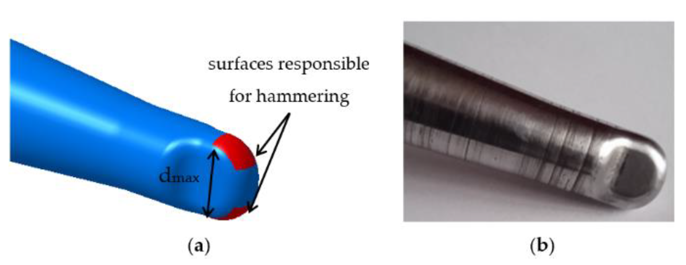
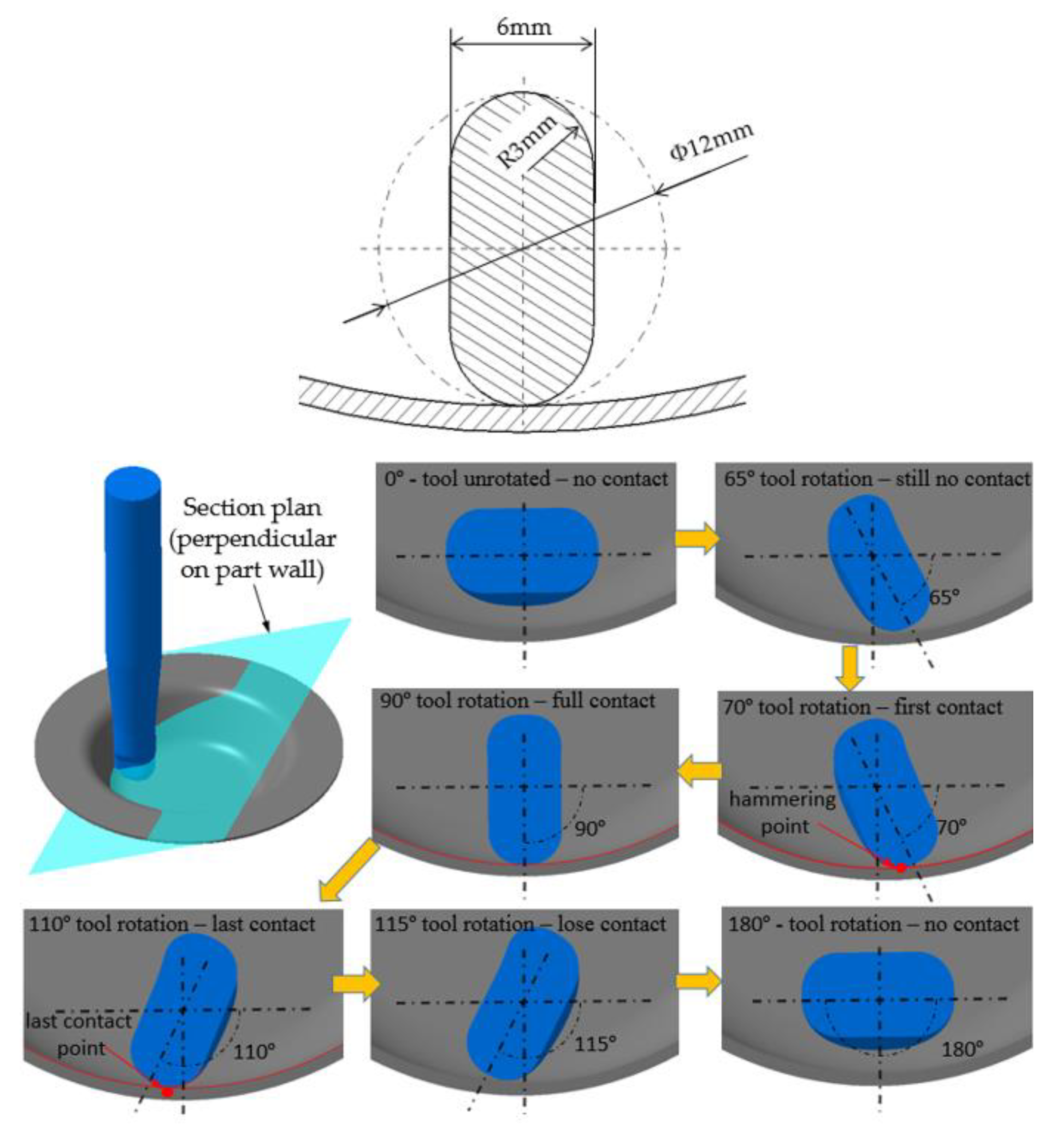
2.1. Tool Shape Concept and Working Principle

The authors propose a different tool design for SPIF in order to achieve better wall surface accuracy compared to the conventional tools typically used in this field.
The proposed tool design is based on a conventional hemispherical forming tool from which the material is removed on two sides in order to obtain a flattened active tool head, as presented in Figure 2.
These parallel surfaces of the flattened active tool head eliminate radial contact between the surfaces of the tool head and sheet blank, creating a free space between them, twice on a complete tool rotation. During tool rotation two types of interactions can be identified between the tool head and sheet blank surfaces, according to Figure 3. Thus, every 0°, 180° and respectively 360° around the tool axis, the contact between tool and sheet blank occurs only on the tool nose surface, and every 90° and 270° the radial side of the tool also comes into contact with the part wall.
Therefore, according to the above presented details, two times per rotation (on each 180° rotation) the tool comes into radial contact with the part wall in a dynamic manner. The schematic in Figure 4 illustrates how—mimicking a hammer that hits the material—a point from the tool head circumference comes into dynamic contact with the part wall following a radial trajectory. Thus, this tool works by the hammering principle by rotating by its own axis, without using special compensated movements or other auxiliary devices or special toolpaths. Because the hammering effect is due to the tool head circumference, the working principle is considered circumferential hammering [5].
In reference to its working principle the novel designed tool presented in this paper is further called circumferential hammering tool (CHT), while the acronym CT stands for conventional forming tool.
Basically, the CHT has the same dimensions as the CT, with the distinction that the CHT active head presents two parallel flattened surfaces at 6 mm distance positioned symmetrically to the plane that includes the tool axis. According to Figure 3 and Figure 4, during a single rotation, CHT head geometry enables two circumferential hammering cycles, meaning that the tool hits the part wall material twice with its active head circumference.

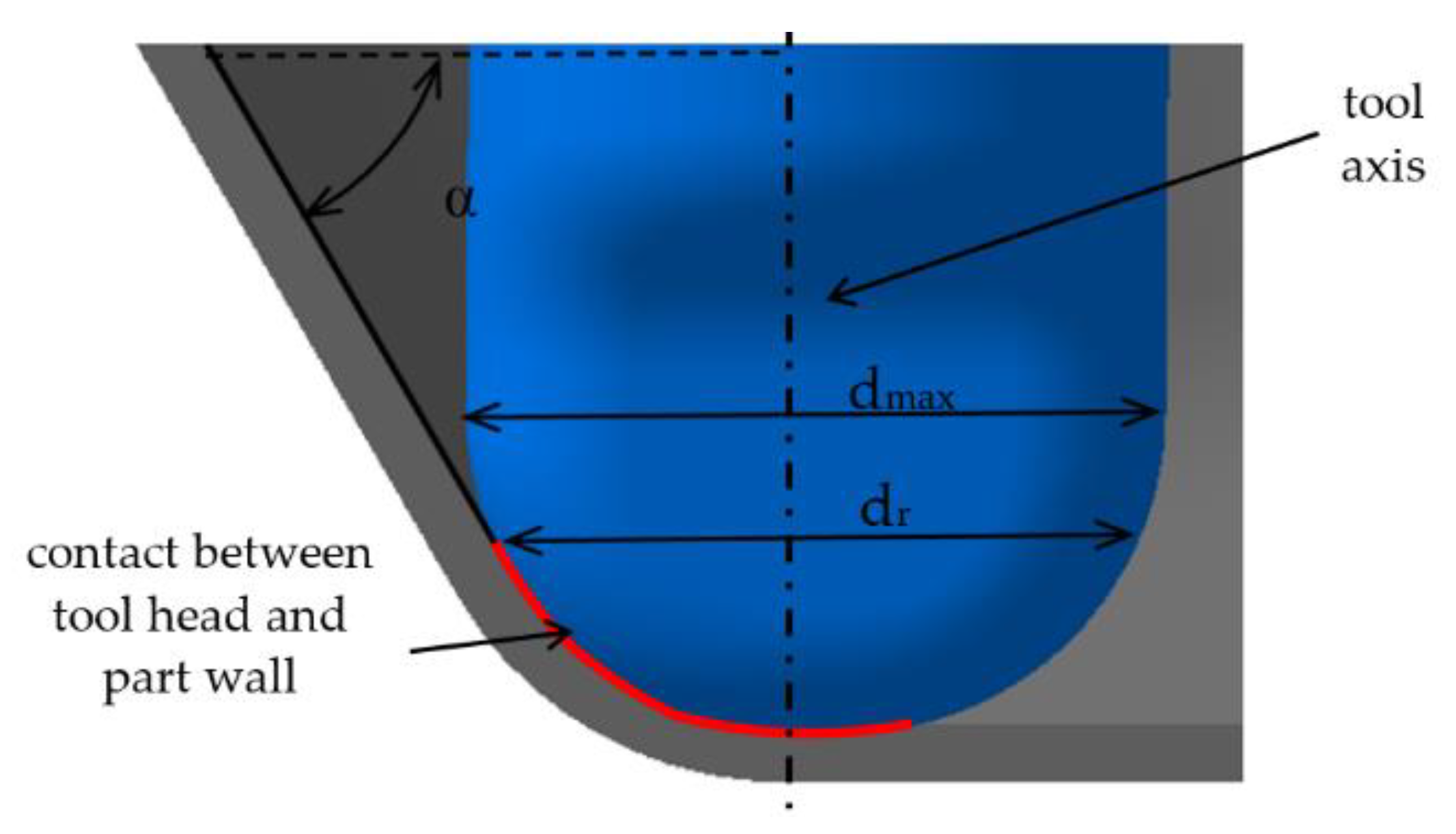
2.2. Theoretical Aspects

During the forming process, due to its spindle speed the CHT accumulates kinetic energy that is downloaded into the sheet metal blank at every 180° rotation of the tool by its own axis. The dynamic contact between the CHT and the sheet blank tends to increase the local plastic deformation, radially pushing the part walls apart. Thus, the strain level in the contact areas is also increased and finally wall part springback amplitude is reduced. The hammering force is generated mainly by the CHT outer surface of the tool active head, because those surfaces have the greatest tangential speed, which is, in fact, the hammering speed. Therefore it can be noticed that the red areas in Figure 5 are the only tool areas which act as hammering surfaces. At the same time it has to be mentioned that the circumferential hammering principle can yield positive results in terms of accuracy only for those areas of the part that can come into contact with the active surfaces of the tool, mainly meaning the tapered walls of the part.
The hammering speed can be described in a similar manner to the cutting speed in milling with a ball nose end mill. The number of flutes of ball nosed end mills is equivalent to the number of hammering surfaces in circumferential hammering tools. Being a hemispherical forming tool, measured from the tool axis the active head diameter corresponding to the red surfaces is continuously changing, starting from 0 (TCP—tool center point) up to the maximum tool diameter. The maximum tool hammering speed is used to calculate the largest tool head diameter, dmax, and the real contact diameter, dr is used to calculate the real tool hammering speed. The real contact diameter, dr, depends on the active tool head diameter, dmax, and on the draw angle of the part, α (Figure 6).
By association with the cutting speed in milling [41], the maximum hammering speed for a tool, Vhmax, can be calculated by the following mathematical formulas:
V hmax = π · d max · n 1000 ,
where:
  • Vhmax—maximum hammering speed of the tool, in m/min;
  • n—tool spindle speed, in rpm;
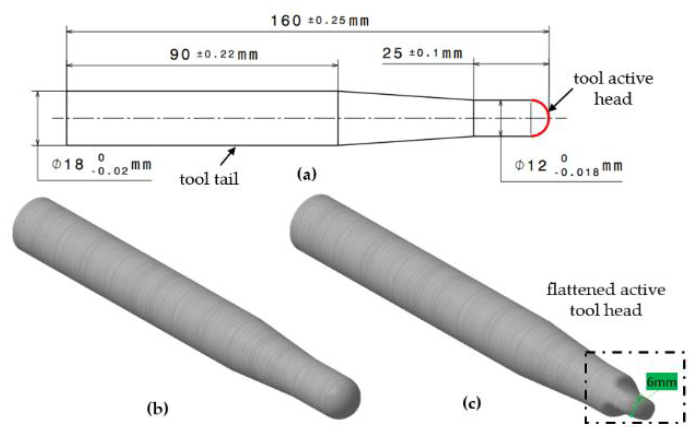
  • dmax—active tool head diameter, in mm.
Because, however, the maximum hammering speed is available only when the part walls are perpendicular on the part flange, meaning they are parallel to the tool axis (α = 90°), the real hammering speed, Vhr, should be calculated by Equation (2):
V hr = π · d r · n 1000 ,
where:
  • Vhr—real maximum hammering speed of the tool, in m/min;
  • dr—real contact diameter, in mm.
According to the Equations (1) and (2), the hammering speed is variable and depends on the tool spindle speed and the hammering diameter. The real contact tool diameter, dr, can be calculated in function of the tool diameter, dmax, and the wall draw angle, α, by Equation (3):
d r = d max · sin ( α )
The real hammering speed of the tool, Vhr, becomes:
V hr = π · d max · n · sin ( α ) 1000 ,
Another critical aspect to be considered as well is the number of hits carried out by the hammering surfaces in relation to time or to a certain distance from the tool trajectory. Equation (5) is used to determine the number of hits per minute, hmin, and Equation (6) for the number of hits per one millimeter, hmm:
h min = n · h s ,
h mm = h min f ,
where:
  • hmin—number of hits per minute, in hits/min;
  • hs—number of hammering surfaces;
  • hmm—number of hits per one millimeter, in hits/mm;
  • f—tool feed rate, in mm/min.
It is assumed that by increasing the number of hits per one millimeter a greater level of strain will be obtained in the contact areas, and therefore the springback amplitude will be reduced increasing part wall accuracy.
Another aspect to be noted is that during a 180° tool rotation by its own axis, only a partial angular interval corresponds to the actual contact between tool and part surface. Hammering tool kinematics is presented in detail in Figure 7, for a particular CHT of diameter dmax = 12 mm, 6 mm between the two flattened surfaces and a 3 mm fillet radius between the outer and the flattened surfaces. The hammering kinematic cycle is represented for a part having a wall angle α = 60°. Figure 7 also features the working stages of the tool during a half rotation of the tool by its own axis (from 0° to 180°). At the beginning, prior to any rotation the tool has no contact with the side wall of the part. Once the spindle is driven into motion, the active surfaces of the tool starts turning, but does not touch the wall until a rotation angle of 65° is reached. At an angle of about 70° a first interaction of the tool with the side wall of the part occurs, namely a dynamic contact that causes the hammering effect. Between approximately 70° and 110° the forming tool is in radial contact with the sheet blank, and since before reaching 115° the tool loses contact until 180° when the hammering cycle resumes. Basically, the CHT repeats this cycle two times and carries out two hits on the sheet metal blank on each rotation.
Taking into consideration the theoretical assumptions presented above, a tool working by the circumferential hammering principle should be able to improve wall accuracy in parts machined by SPIF without requiring additional solutions that can be complex, expensive or difficult to implement in the process.

2.3. Experimental Research

In order to validate the initial assumption about circumferential hammering efficiency in terms of part wall accuracy improvement, preliminary tests were conducted consisting of experimental trials of machining several frustum-of-cone shapes with the circumferential hammering tool (CHT). Similar frustum-of-cone shapes were machined with a conventional tool (CT) and the results were compared.
Advanced research was further conducted in order to investigate the influence of the process parameters upon part dimensional accuracy in the wall areas.

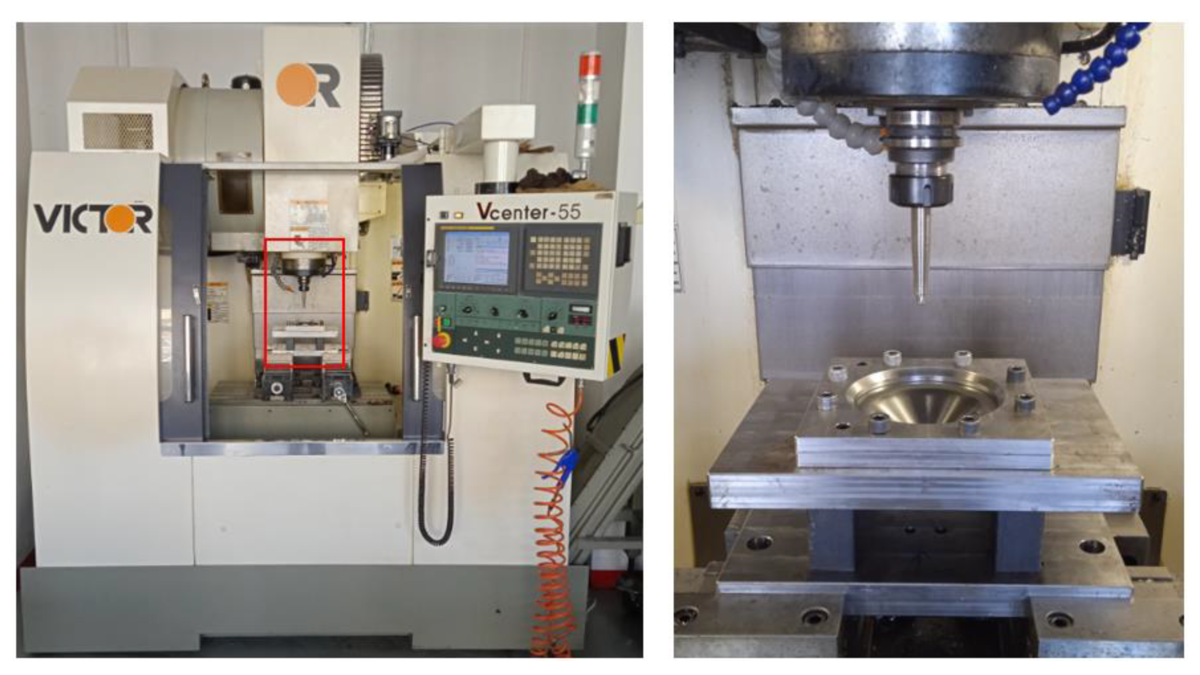
2.3.1. Materials and Technological Setup

The parts to be used in the experimental trials were manufactured from square sheet metal blanks of DC05 deep drawing steel of 1 mm thickness. All experiments were conducted on parts of a single shape, a frustum of a cone, in different dimensional configurations. The dimensional configuration of each part is identified by the following codification rule using the symbols shown in Figure 8: symbol “D” followed by the value of the upper base diameter of the part, next to symbol “H” followed by the value of the part height, symbol α” followed by the value of the wall angle, and symbol “Δz” followed by the value of the incremental step depth. The diameter, the height and the step depth are expressed in millimeters and the wall angle in degrees [5]. For instance, the part codification “D95H45α50Δz0.5” means a dimensional configuration with a 95 mm upper base diameter, 45 mm height, 50° wall angle and is machined with a 0.5 mm incremental step depth.
The technological setup (presented in Figure 9) used for SPIF consists of the following elements [42]: a three-axis Victor Vcenter-55 CNC milling machine (VICTOR TAICHUNG, Taichung, Taiwan), a high rigidity sheet metal clamping device [2], and two forming tools with different shapes already presented in Figure 2. Both tools were manufactured from C45 steel by turning and milling. In order to improve active tool head life and to maintain tail tenacity, both tools were heat-treated (hardening followed by tempering) yielding a hardness of about 270 HB.

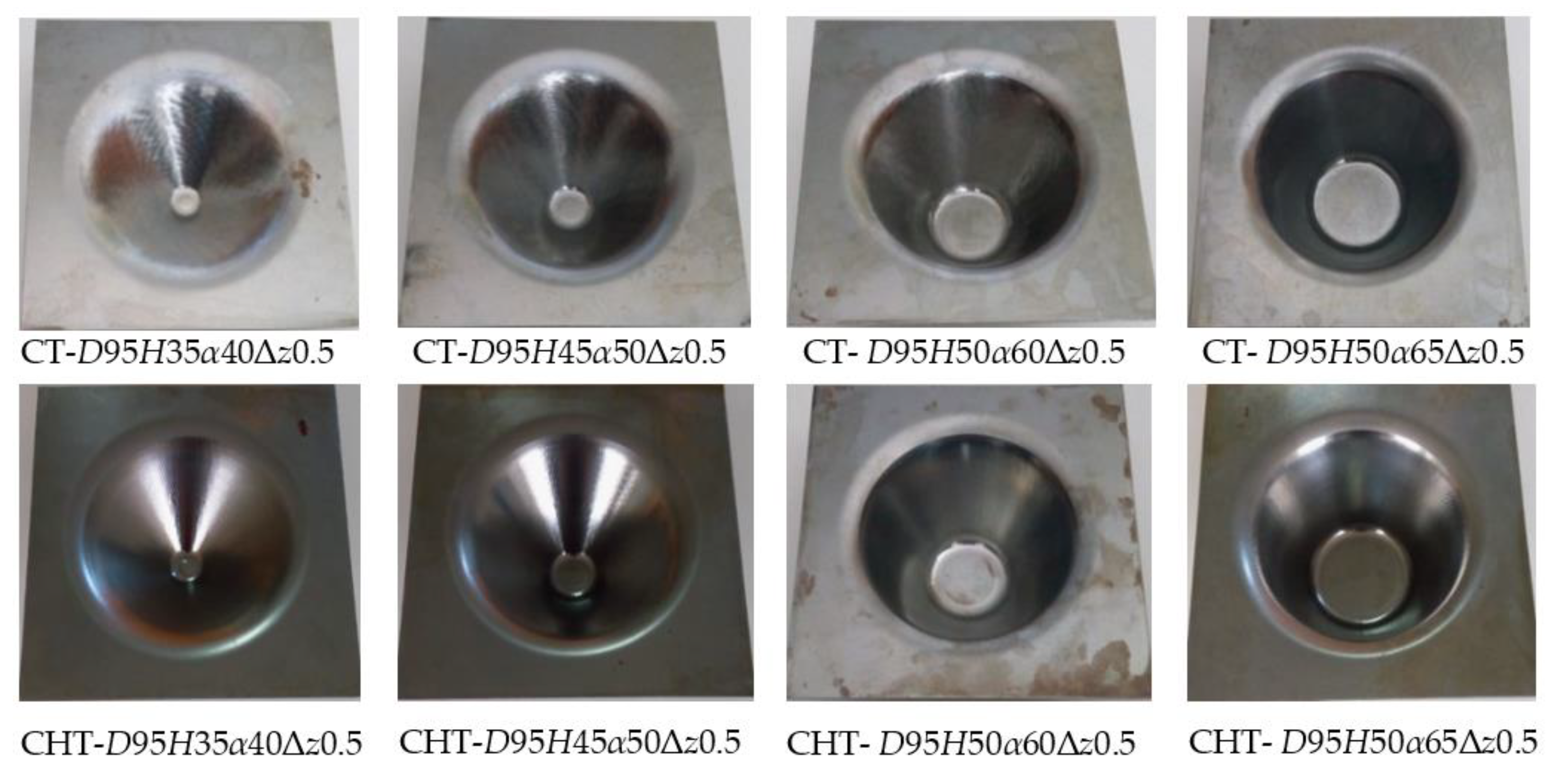
2.3.2. Preliminary Tests

Even if conventional forming tools (CT) are typically used in SPIF processes, in the discussed experiments a CT was used merely for the purpose of comparing its efficiency under the same experimental conditions to the expected efficiency of the CHT tool in terms of part accuracy.
Preliminary tests were performed in order to prove the initial assumption regarding the circumferential hammering efficiency, by comparing the accuracy values obtained by using the CT and the CHT tools, for the same shape and dimensional configurations associated to the parts. Four frustum-of-cone parts, in various dimensional configurations, were machined by both tools, as presented in Table 1.
According to Equations (2) and (6) the main process parameters that influence the tool real hammering speed, Vhr and the number of hits per millimeter, hmin, are the tool spindle speed and the feed rate. For the SPIF process parameters the same values were maintained for all eight trials, as follows: tool spindle speed n = 1000 rpm and feed rate of f = 1500 mm/min. A 0.5 mm incremental step depth was used in the forming strategy that entails a usual spiral toolpath generated by means of CATIA V5, the advanced machining workbench. Mineral oil was used for contact areas lubrication in order to decrease the friction between the tools and the sheet metal blank. The upper base diameter of the parts was D = 95 mm in all configurations, while the wall angle varied ascending, from 40° to 65°. The largest wall angle value (65°) was selected such as to avoid material fracture, being known that the wall angle limit for DC05 deep drawing steel before material fracture occurs is smaller than 70° [5]. Regarding part height, it needs noted that it was not possible to maintain a constant value of 50 mm for all four configurations because of the dimensional constraints imposed by other two parameters, the upper base diameter and the wall angle. All parts were machined free of material fracture; they are presented in Figure 10.
In Figure 10 for ease of identification, part names are preceded by the acronym CT or CHT referring to the forming tool used in the machining process.
After machining several measurements are required for each part configuration in order to compare wall dimensional accuracy obtained by using both forming tools. 3D scanning technology was selected as the method of measurement due to its important benefit of generating an entire scanned part surface. This virtual surface allows easy comparison to the desired 3D CAD model that was initially designed for machining. Unlike the coordinate measuring machine that needs complex additional preparations, 3D scanning technology allows users to measure parts rapidly and in any direction, with a good measuring precision (approximately 9 μm accuracy) for parts machined by ISF or other cold forming processes. Figure 11 shows the measuring setup.
In order to measure the machined parts, the 3D scanning method requires going through a few basic steps. The first step is the effective digitizing of the part by means of a Comet L3D blue light scanner (Steinbichler Optotechnik, Neubeuert, Germany); a point cloud of the part surfaces is obtained from the side where the tool acted during the forming process. The point cloud is then processed by two CATIA V5 workbenches (Dassault Systemes, Vélizy-Villacoublay, France), the digitized shape editor and the quick surface reconstruction, yielding the final part surface. This surface was matched against the 3D CAD model of the part, based on the coincidence of the part axis and the planar surfaces of the part flange. The incongruities between the CAD model and the digitized surface were measured for each part in three different points on the height of the part, in a section plane along the part axis (Figure 12). The values measured for those three positions are in fact part deviations, denoted by P1, P2 and P3 as follows: P1—the deviation value in the first measurement position at 3/4xH (H is the part height), P2—the deviation value in second measurement position at 1/2xH, and P3—the deviation in third measurement position at 1/4xH [5].
Figure 13 shows an example of the measured deviations for a D95H35α40Δz0.5 part configuration, machined by both forming tools. The measurements were performed on the final part after onset of the springback effect, thus also taking into account the elastic deformations of the part.
The values for deviations P1, P2 and P3 for all manufactured parts were centralized and graphically represented in Figure 14. It can be easily observed that in all four part configurations the deviations from the CAD model measured on the parts machined by the CHT are significantly smaller than the deviations measured on the parts machined by the CT. An average percentage of dimensional accuracy improvement achieved consequently to using the CHT was also determined in order to obtain an overview of the overall results.
Figure 15 shows the hit marks left by the tool on the surface of the part in a detailed view of the deformed surface of part configuration D95H45α50Δz0.5 generated by optical zoom on a Mitutoyo TM-1005B microscope (Mitutoyo, Japan).
The obtained results demonstrate the correctness of the initial assumption according to that part wall accuracy is considerably improved by using a circumferential hammering tool (CHT) compared to the accuracy of obtained by using a conventional tool (CT).
Based on the preliminary tests, it is thus proved that dimensional accuracy can be significantly improved by replacing the conventional tool by a special one working by the circumferential hammering principle. The greatest benefit of this new improvement method is its applicability without any additional effort or investments, thus avoiding the necessity of implementing complex and expensive additional solutions, as discussed in Section 1 of this paper. The forming process is basically unchanged and is easily put into practice under the same conditions as s conventional SPIF process. The circumferential hammering technique yields desired results only in those areas of the part where the outer hammering surfaces of the CHT are engaged in machining. This means that the CHT can improve part accuracy only for the surfaces of the tapered walls.
Due to the results obtained in the preliminary tests presented above, it was decided to extend the research by determining the influence of process parameters like tool spindle speed and feed rate on the dimensional precision obtained by forming with a circumferential hammering tool (CHT).

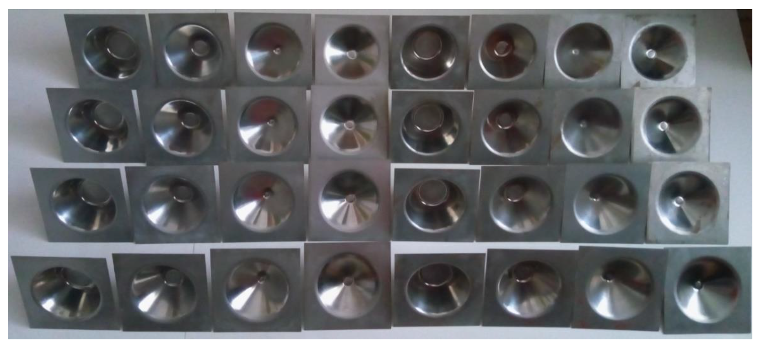
2.3.3. Extended Experimental Research

Once proved that using a CHT instead of a CT yields a better accuracy of the part walls further extending of the experimental research was decided. The experiments carried out as part of the extended research were aimed at investigating the influence of process parameters, namely tool spindle speed and feed rate on the wall area accuracy of the parts. According to Equations (5) and (6) the major influence on the number of hits carried out by the CHT during the forming process is due to tool spindle speed and feed rate are. It is assumed that the more often the blank surface is hit by the CHT the better the dimensional precision will be, because the strain level in the wall material is increased, reducing the negative influence of springback. Hence, it is considered that the only two process parameters, except the tool diameter, that are able to influence the dimensional accuracy of the parts are tool spindle speed and the feed rate. Consequently, it was decided to conduct more elaborate experimental research in order to determine mathematical models predictive of the dimensional precision that can be obtained for different values of the tool spindle speed and feed rate, in case of frustum-of-cone shapes. For this propose, Minitab was selected as the software tool to manage the experimental trials according to a well-known technique, design of experiments (DOE).
According to Equation (2), tool hammering speed is increased when the real contact diameter of the tool, dr, is as close as possible to the active tool head diameter, dmax. The real contact diameter of the tool, dr depends on the part wall angle (Figure 6). Thus, for the array of experiments as part of the extended research, it was decided to variate the draw angle of the part (α), keeping constant the diameter of the forming tool along with the rest of the dimensional parameters of the part. Because of the dimensional constraints due to the geometric shape (frustum of a cone), however, it was not possible to keep the other two parameters constant, namely part height (H) and upper base diameter (D), and to variate only the draw angle of the part. Thus, it was decided to include the entire dimensional configuration of the part as a single influencing factor in the array of experiments devised by DOE. The factors are assigned codes according to the rule presented in Section 3.1.
Therefore, the dimensional accuracy of part walls will be analyzed in function of three influencing factors: the tool spindle speed, tool feed rate and dimensional configuration of the part. The array of experiments includes trials on frustum-of-cone shapes in four-dimensional configurations machined by using two levels for tool spindle speed and feed rate, according to Table 2 that also features the factor levels and their symbols. It was assumed that two levels are sufficient to describe the influence of tool spindle speed and feed rate on the dimensional precision of the part walls.
The experiments were run by a full factorial array and considering one of the most important principles of DOE technique, replication, a total number of 32 trials were carried out in a random order generated by Minitab software. All 32 parts were machined in good conditions, free of material fracture, using the same technological setup and the same square blanks of DC05 deep drawing steel as in the preliminary tests. Figure 16 shows all machined parts: on the right-hand side the first batch of all factorial combinations, and on the left-hand side their replicas.
The replicas are used to verify the repeatability of the circumferential hammering SPIF process. The replicas were machined in the same random order generated by Minitab software.

3. Results and Discussion

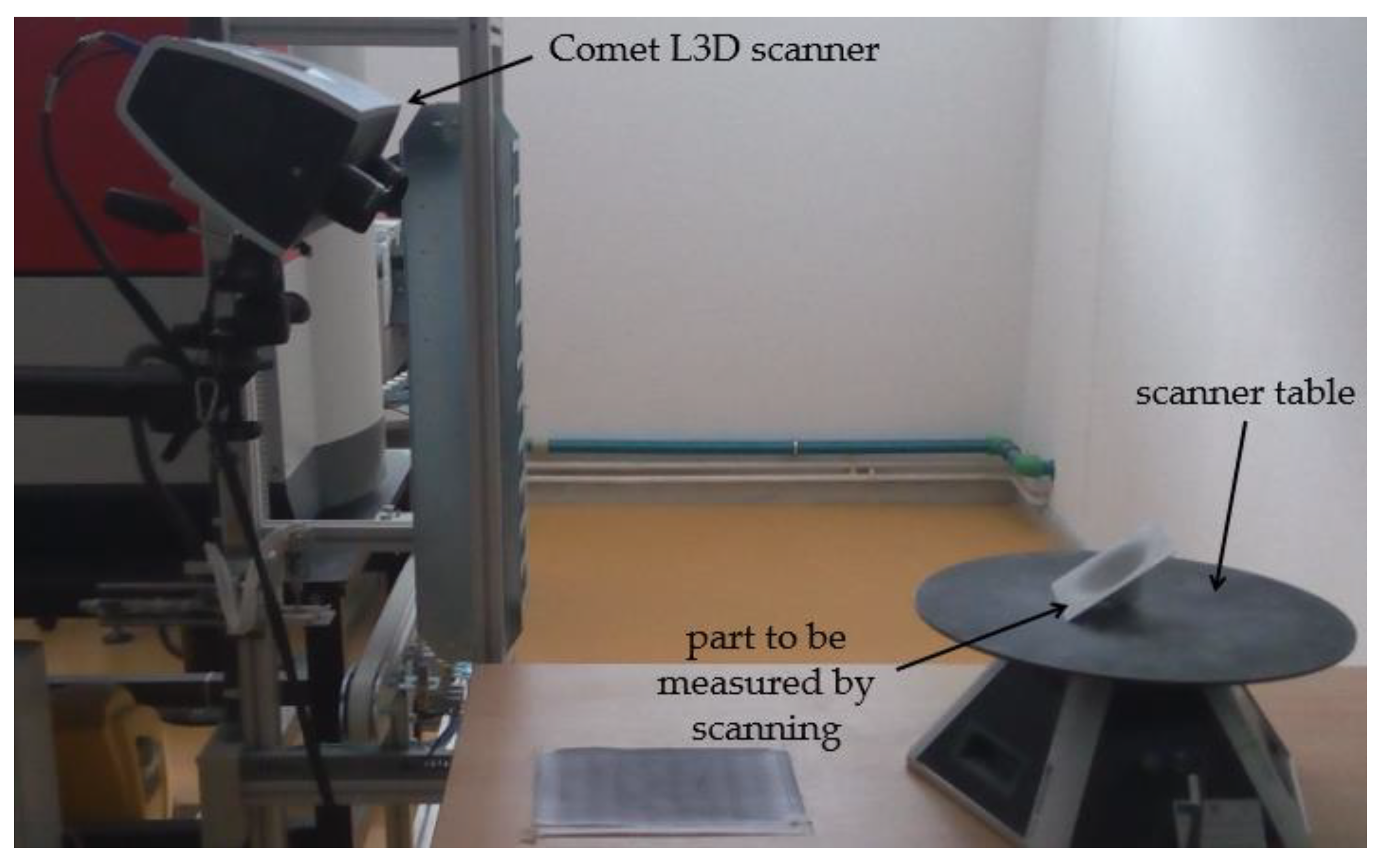
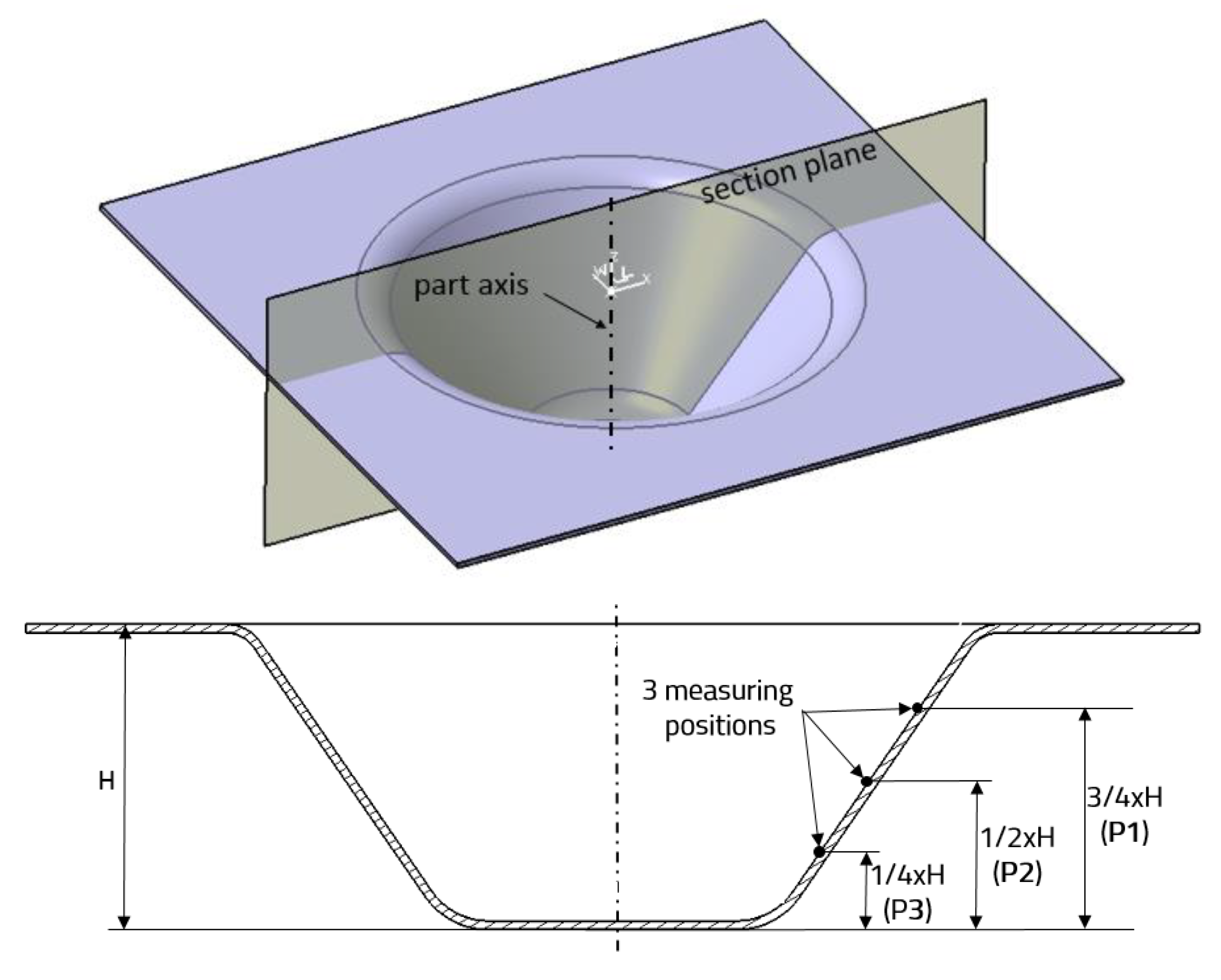
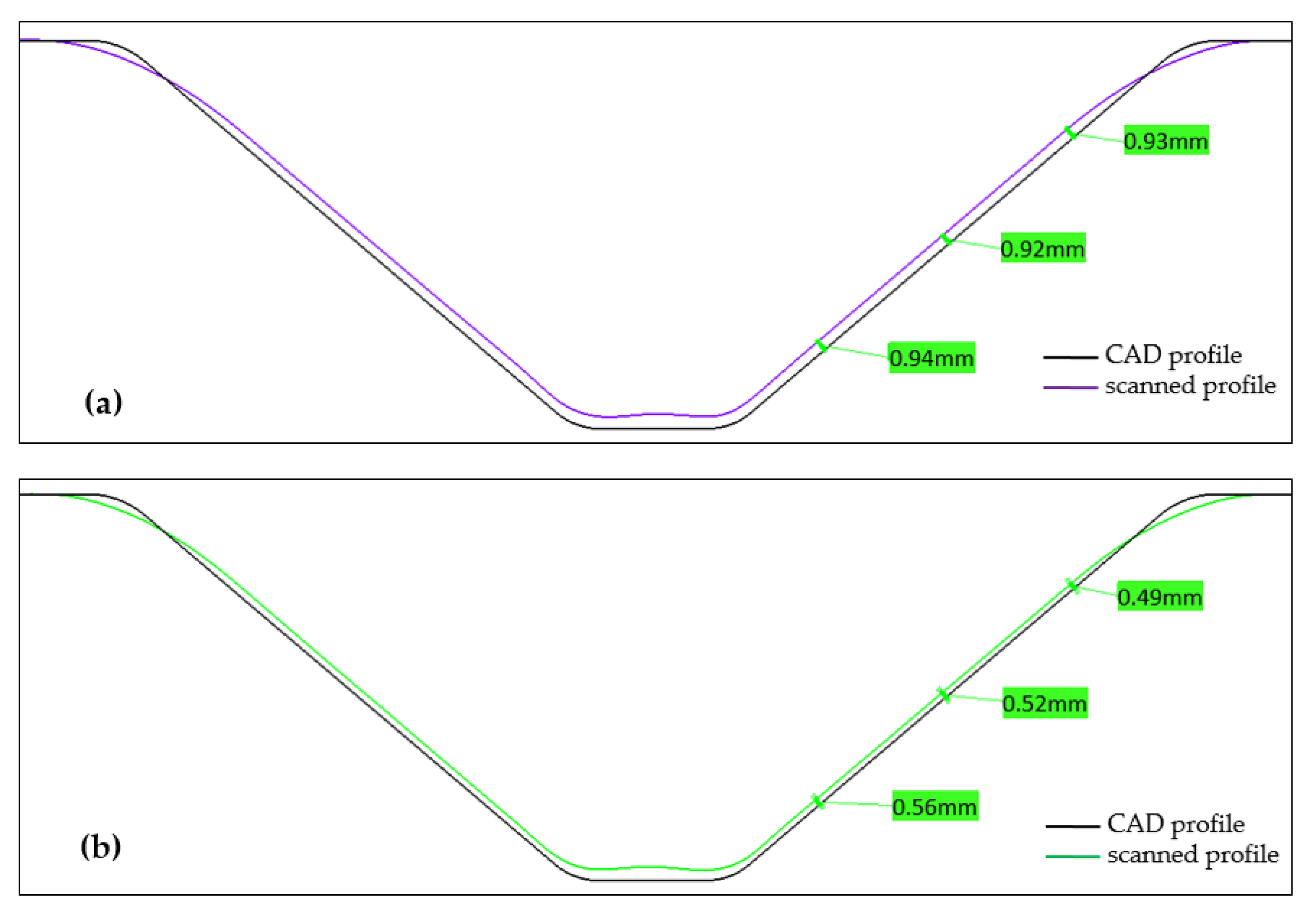
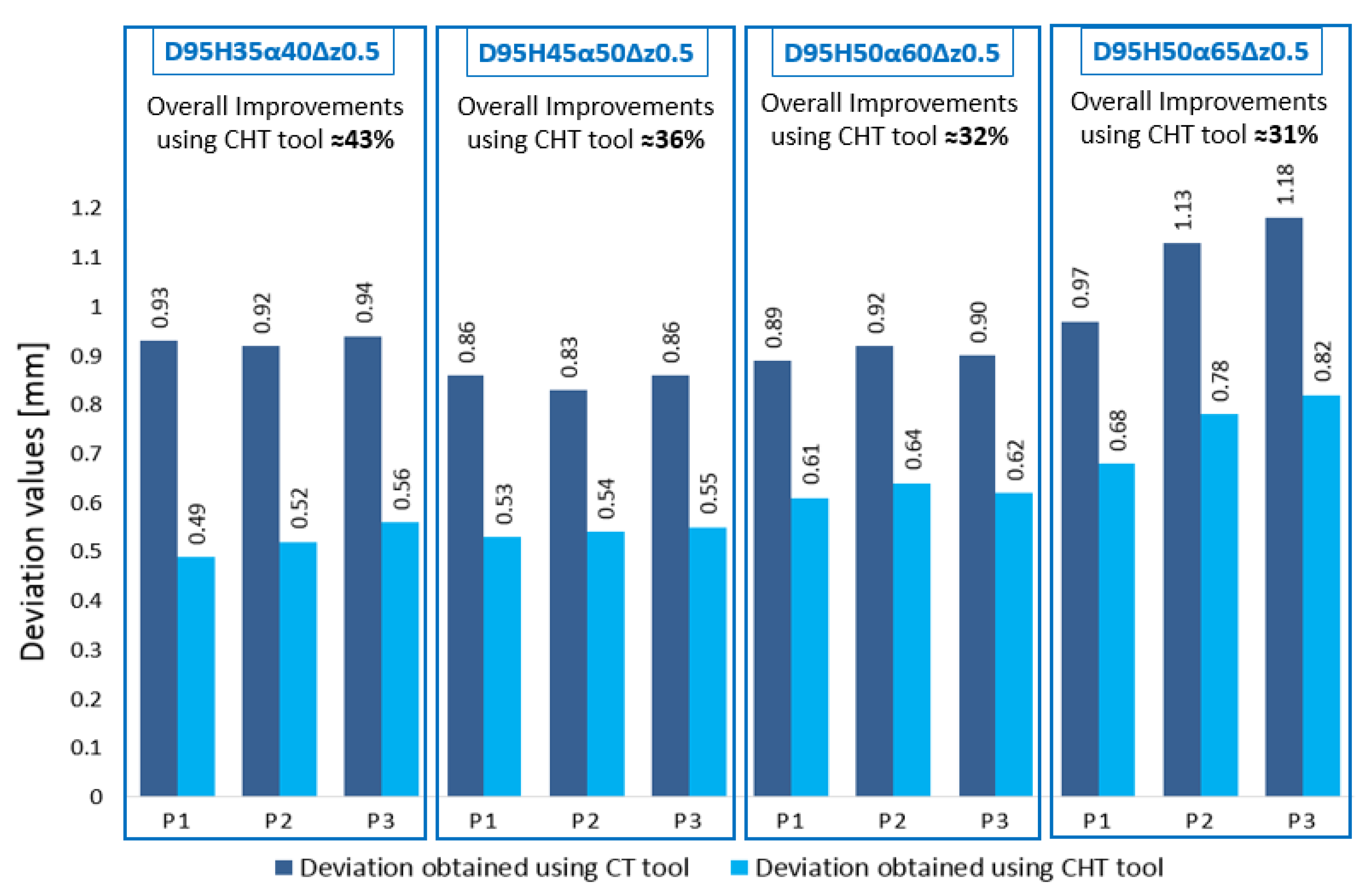
3.1. Part Deviation Measurements

In a similar manner to the measurement of the parts carried out in the preliminary tests, deviations P1, P2 and P3 were investigated for all parts machined within the extended experimental research. By comparing the scanned surface to the theoretical CAD model, the deviations P1, P2 and P3 were determined in three different positions according to Figure 12.
Each experimental trial is a different combination of one of the levels of factor CONF (part configuration) factor n and factor f, respectively. For ease of identification of each trial, these were assigned codes using the symbols from Table 2. For instance, trial C1-n1-f1-r1 represents the first dimensional configuration of the part, C1 (D100H30α35Δz0.5), machined with a spindle speed of 1000 rpm, n1, and a tool feed rate of 1000 mm/min, f1, this being the first trial replica (r1). Table 3 includes the measured values of P1, P2 and P3 in all 32 trials.
The values presented in Table 3 were introduced into Minitab, as the responses corresponding to the full factorial experimental plan, and were statistically processed, using the regression analysis.

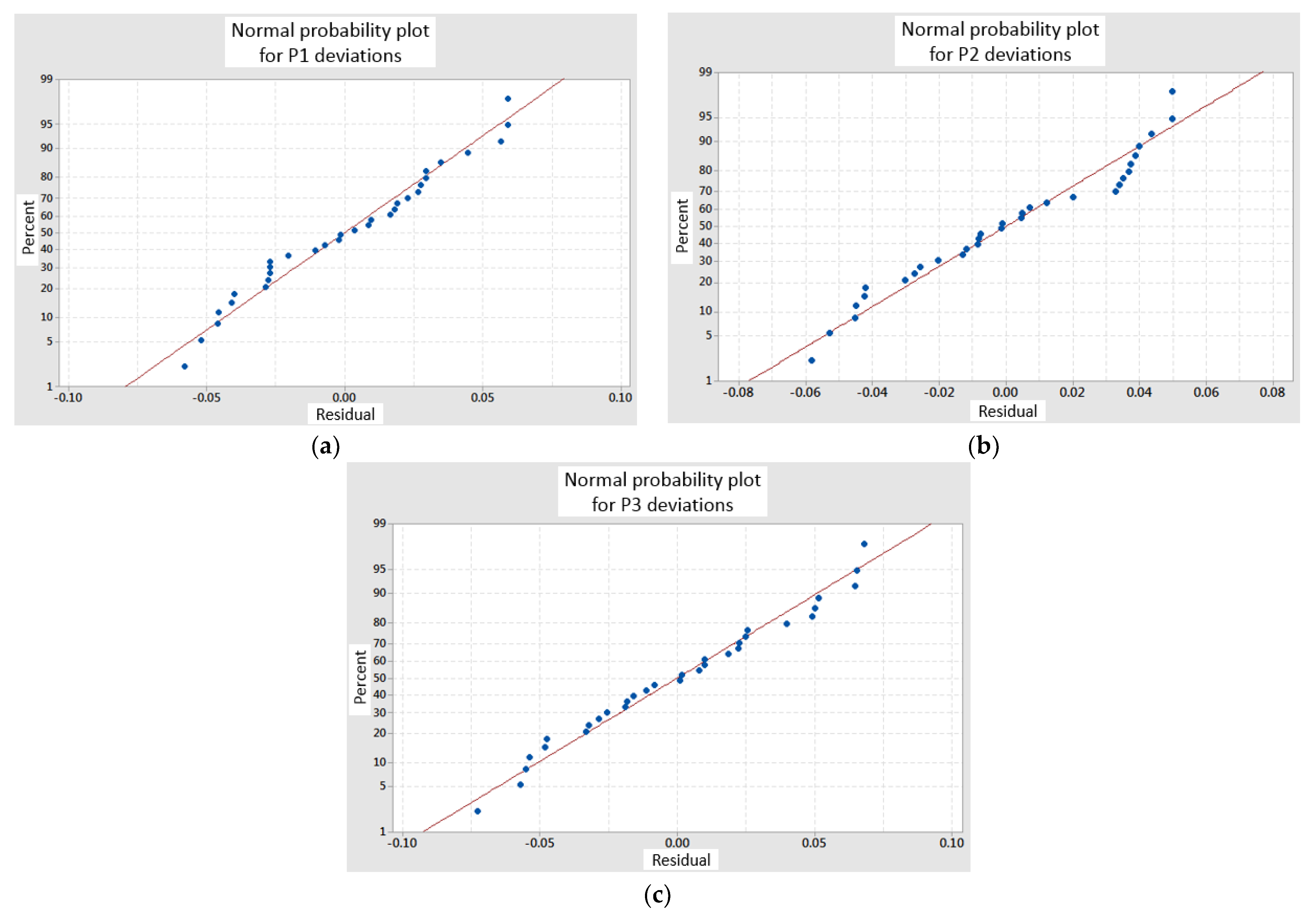
3.2. Mathematical Models Used for Part Accuracy Prediction

Regression analysis is one of the most efficient methods to highlight the factors that influence the final results or responses. As discussed, the draw angle of the part wall could not be varied while keeping all other dimensions of the part constant, and consequently the entire dimensional configuration of the part was considered as a single factor, being a categorical predictor. Because the dimensional configuration of the part could not be introduced, however, as a continuous predictor for the analysis, the regression method was applied individually for each dimensional configuration. Because the values for all P1, P2 and P3 deviations were measured in three different positions on the part wall, regression analysis led to the following three mathematical models [5]:
P 1 = k 1 + 0.000017   n + 0.000052   f ,
P 2 = k 2 + 0.000012   n + 0.000046   f ,
P 3 = k 3 + 0.000004   n + 0.000041   f .
The mathematical models presented above can be differentiated for each dimensional configuration by replacing in Equations (7)–(9) the values of coefficients k1, k2 and k3 specified in Table 4.
Even if the dimensional parameters of the parts could not be varied individually, as already mentioned, it is the draw angle of the part, α, that has the most significant influence on part accuracy, because its value increases or decreases the real contact diameter of the tool, dr, which further influences the hammering speed Vhr. The influence of the other two parameters, height H and upper base diameter D was considered insignificant compared to the wall angle, and consequently could be neglected.
The mathematical models obtained by regression analysis of the results corresponding to the array of experiments implemented as part of the extended research lend themselves to accuracy prediction for frustum-of-cone shapes machined from DC05 deep drawing steel by SPIF processes using a circumferential hammering tool.

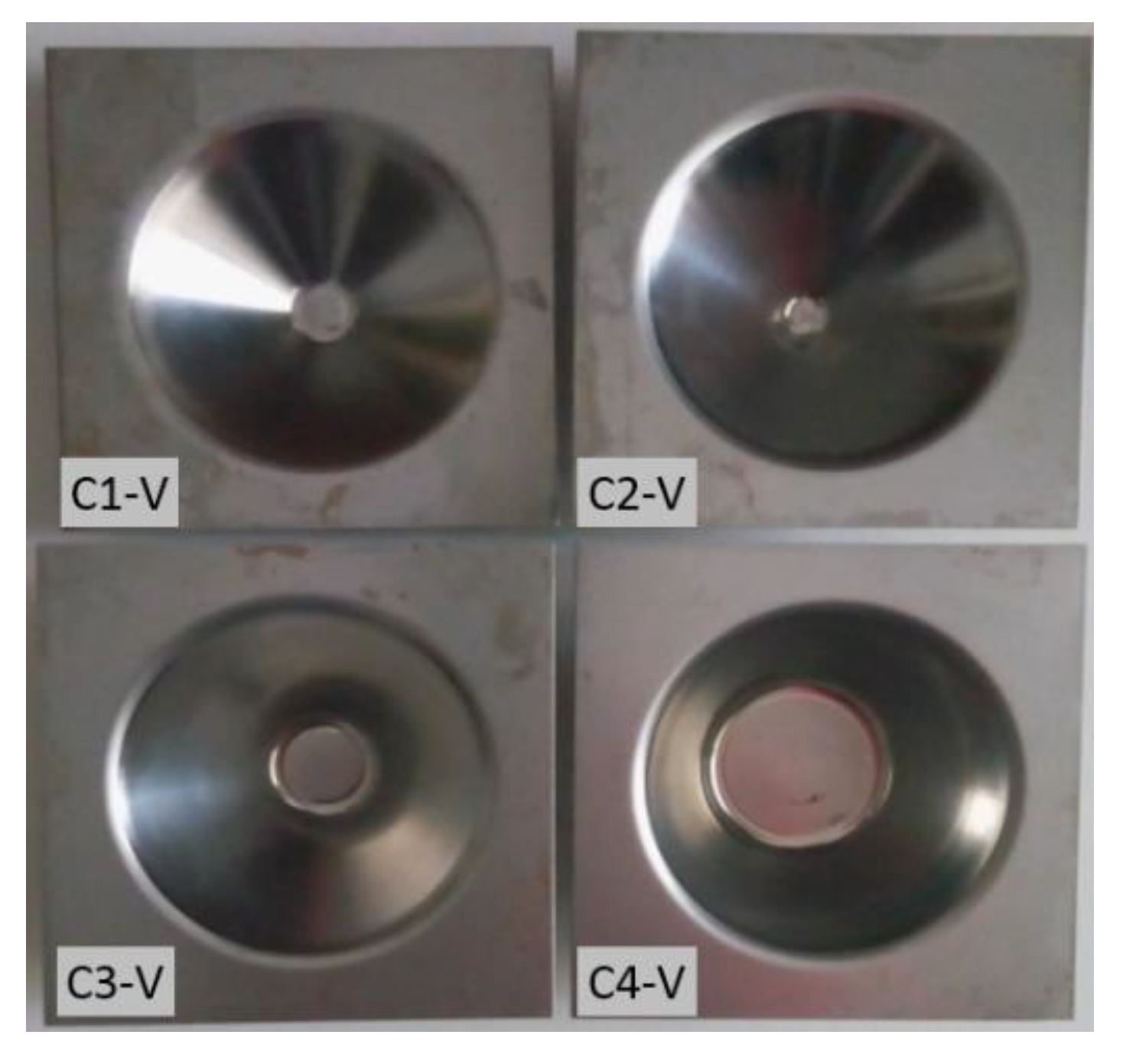
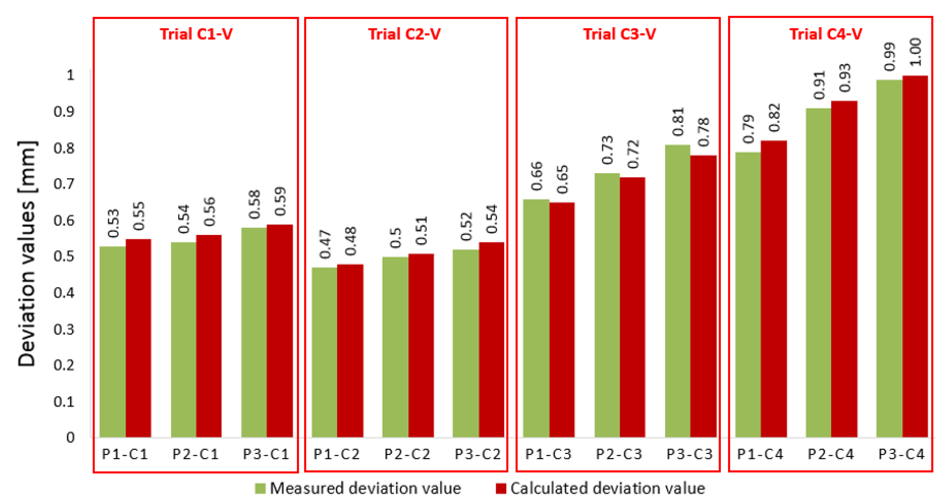
3.3. Practical Validation of the Mathematical Models

The confidence of the regression analysis is confirmed by the statistical parameters standard deviation S and coefficient of correlation R2 (Table 5) and the probability plots (Figure 17). Still, it was decided to conduct a validation by practical experiment of the mathematical models describing the dependency between the dimensional accuracy of the part walls and the process parameters (tool spindle speed and feed rate).
Thus four more parts were machined, one for each dimensional configuration, using intermediate values for the tool spindle speed and feed rate. Considering the values used in the array of experiments a mean spindle speed of 1250 rpm and a mean feed rate of 1250 mm/min were selected for the validation of the mathematical models for all four machined parts. Figure 18 shows the four parts that were machined adequately. Hence, the symbol “V” for “validation” was added to the respective configuration indices C1, C2, C3 and C4 [5].
In order to validate the confidence of the obtained Equations (7)–(9), the predictions given by the mathematical models are compared to the deviations measured on the four parts presented in Figure 18. Figure 19 shows the comparative results of the measured and predicted (calculated) values for deviations P1, P2 and P3.
By analyzing the values presented in Figure 19, it can be noticed that the predicted deviations are very close or almost match the real measured values. The graphs further show that the greatest difference between the measured and the predicted deviation is of about 0.03 mm for deviation P3 in the third configuration and for deviation P1 in the fourth configuration. All other differences are less than 0.02 mm. Thus, it can be observed that the mathematical models obtained from the regression analysis lend themselves to accuracy prediction for cone-shaped parts machined with a circumferential hammering tool, ensuring sufficient precision for a SPIF process.

4. Conclusions

The paper presents in detail and discusses a study concerning a novel method for improving wall accuracy of parts machined from DC05 deep drawing steel by SPIF. The method uses the principle of circumferential hammering that is implemented by means of a special tool design. In-depth discussion is offered of the circumferential hammering phenomenon, hammering tool kinematics and theoretical aspects regarding the process parameters. The initial assumption according to that the utilization of a circumferential hammering tool improves wall accuracy was validated experimentally for frustum-of-cone parts in preliminary tests. Extended experimental research was further conducted for different dimensional configurations of the considered part, in order to investigate the influence of tool spindle speed and feed rate on wall accuracy. Three mathematical models were determined and practically validated for part accuracy prediction. The key conclusions of this study are the following:
  • The improvement method using the principle of circumferential hammering is implemented by simply replacing the conventional forming tool with a circumferential hammering one, without the necessity of implementing other complex solutions, additional setups or other elements that can be expensive or difficult to be managed. This method requires no special preparation stage or special skills, as the SPIF process toolpath strategy and technological setup remain basically unchanged.
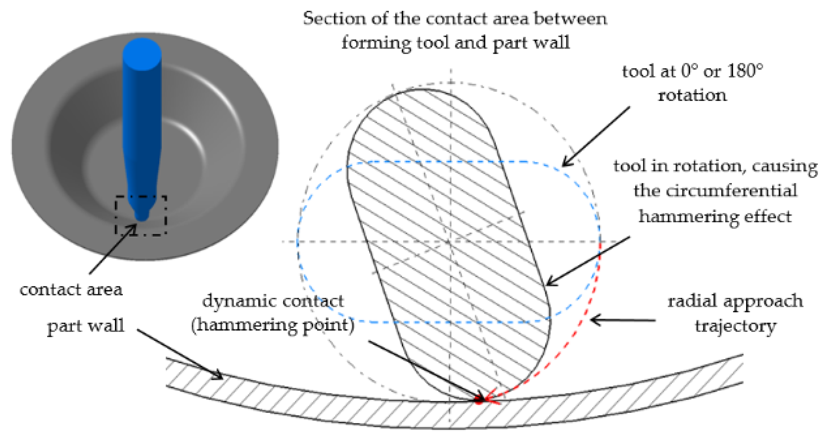
  • Taking into account the theoretical aspects, the real hammering speed is influenced by the real contact diameter of the tool that depends on its turn on the taper angle of the part. The number of hits carried out by the hammering tool depends on tool geometry (number of hammering surfaces according to the tool design), tool spindle speed and feed rate.
  • By using the circumferential hammering tool proposed in the research, the wall accuracy of frustum-of-cone parts was improved by up to about 43%, depending on the dimensional configuration of the part.
  • Extended experimental research was conducted to study the influence of process parameters (tool spindle speed and feed rate) on part accuracy. Based on the deviations of the part in relation to the CAD models, three mathematical models were statistically determined that can be used for accuracy predictions for frustum-of-cone shapes machined from DC05 deep drawing steel by means of a circumferential hammering tool.
  • The mathematical models were experimentally validated, and a good agreement was obtained between the deviations calculated by means of the mathematical models and the real deviations measured on the machined parts.
  • According to deviation measurements on replicated parts, it can be said that the circumferential hammering SPIF process also ensures a good repeatability.
The SPIF process using a circumferential hammering tool is easy to implement and ensures positive results in terms of part wall accuracy, but should be further studied and analyzed from different points of view. This paper opens multiple research opportunities, future research being certainly needed in order to evaluate the benefits of the described improvement method. Several topics that can be further studied include [5]:
  • Research regarding the influence on part accuracy of the active tool head dimensional parameters (number of hammering surfaces, diameter, flattened surfaces width, corner radius).
  • Determination of the maximum values for tool spindle speed, feed rate and wall draw angle, for that parts can be machined free of material fracture.
  • Expanding the research to other part shapes like spherical, hexagonal or complex.
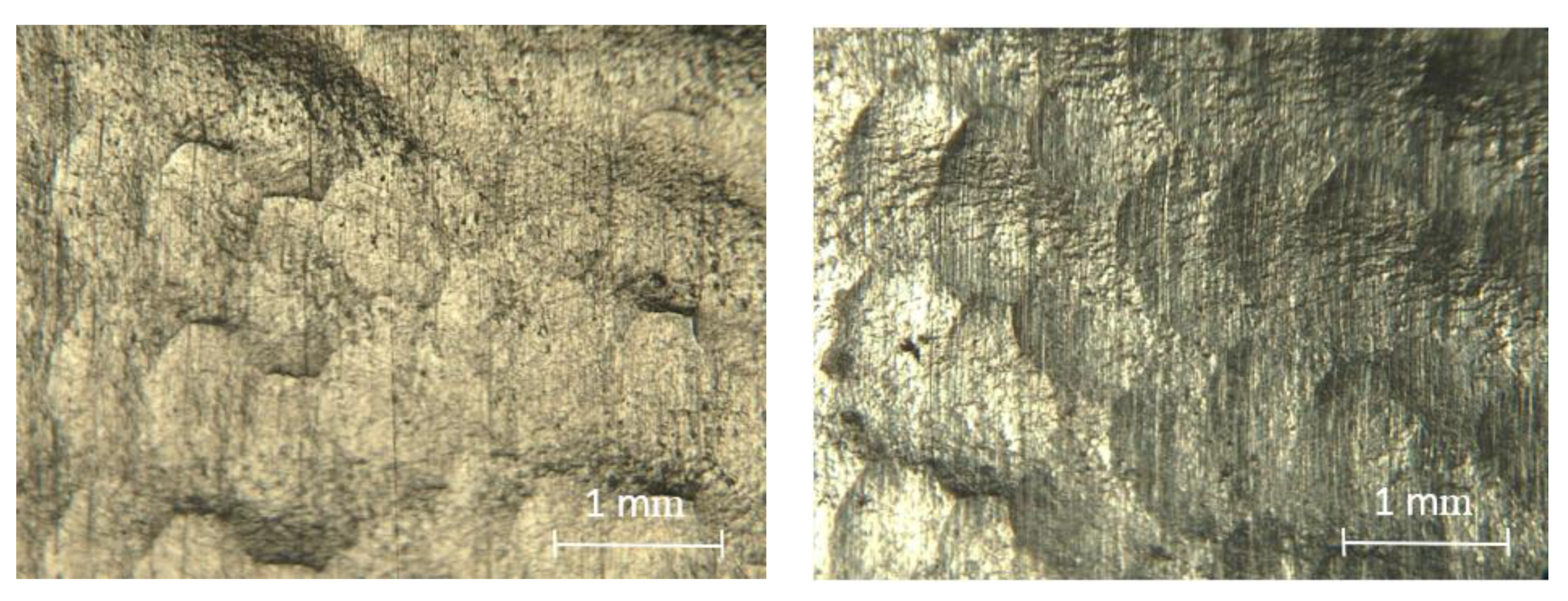
  • Study of the roughness of surfaces deformed by means of circumferential hammering tools.
  • Developing a forming tool with active surface inserts or replaceable active tool heads.

Author Contributions

Conceptualization D.N. and G.O.; methodology D.N. and G.O.; validation D.N. and G.O.; formal analysis D.N.; investigation D.N. and G.O.; resources D.N.; data curation D.N.; writing—original draft preparation D.N. and G.O.; writing—review and editing D.N. and G.O.; supervision G.O. All authors have read and agreed to the published version of the manuscript.

Funding

This research received no external funding.

Institutional Review Board Statement

Not applicable.

Informed Consent Statement

Not applicable.

Data Availability Statement

Data sharing is not applied.

Conflicts of Interest

The authors declare no conflict of interest.

References

  1. Nasulea, D.; Oancea, G. Incremental deformation: A literature review. MATEC Web Conf. 2017, 121, 3017. [Google Scholar] [CrossRef] [Green Version]
  2. Nasulea, D.; Oancea, G. Design and manufacturing of a fixing device for incremental sheet forming process. MATEC Web Conf. 2018, 178, 02004. [Google Scholar] [CrossRef]
  3. Li, L.; Wang, J.; Wang, B. Geometric accuracy of incremental sheet forming for TRIP590. J. Mech. Sci. Technol. 2017, 31, 5257–5264. [Google Scholar] [CrossRef]
  4. Jeswiet, J.; Micari, F.; Hirt, G.; Bramley, A.; Duflou, J.; Allwood, J. Asymmetric Single Point Incremental Forming of Sheet Metal. CIRP Ann. Manuf. Technol. 2005, 54, 88–114. [Google Scholar] [CrossRef]
  5. Nasulea, D. Research Regarding the Incremental Forming of DC05 Steel Sheet Parts. Ph.D. Thesis, Transilvania University of Brasov, Brașov, Romania, 2019. [Google Scholar]
  6. Micari, F.; Ambrogio, G.; Filice, L. Shape and dimensional accuracy in Single Point Incremental Forming: State of the art and future trends. J. Mater. Process. Technol. 2007, 191, 390–395. [Google Scholar] [CrossRef]
  7. Gupta, P.; Szekeres, A.; Jeswiet, J. Design and development of an aerospace component with single-point incremental forming. Int. J. Adv. Manuf. Technol. 2019, 103, 3683–3702. [Google Scholar] [CrossRef]
  8. Lu, H.; Liu, H.; Wang, C. Review on strategies for geometric accuracy improvement in incremental sheet forming. Int. J. Adv. Manuf. Technol. 2019, 102, 3381–3417. [Google Scholar] [CrossRef]
  9. Gatea, S.; Ou, H.; McCartney, G. Review on the influence of process parameters in incremental sheet forming. Int. J. Adv. Manuf. Technol. 2016, 87, 479–499. [Google Scholar] [CrossRef] [Green Version]
  10. Essa, K.; Hartley, P. An assessment of various process strategies for improving precision in single point incremental forming. Int. J. Mater. Form. 2011, 4, 401–412. [Google Scholar] [CrossRef]
  11. Maqbool, F.; Bambach, M. Dominant Deformation Mechanisms in Single Point Incremental Forming (SPIF) and their effect on geometrical accuracy. Int. J. Mech. Sci. 2018, 136, 279–292. [Google Scholar] [CrossRef]
  12. Dai, P.; Chang, Z.; Li, M.; Chen, J. Reduction of geometric deviation by multi-pass incremental forming combined with tool path compensation for non-axisymmetric aluminum alloy component with stepped feature. Int. J. Adv. Manuf. Technol. 2019, 102, 809–817. [Google Scholar] [CrossRef]
  13. Tera, M.; Breaz, R.E.; Racz, S.G.; Girjob, C.E. Processing strategies for single point incremental forming—a CAM approach. Int. J. Adv. Manuf. Technol. 2019, 102, 1761–1777. [Google Scholar] [CrossRef]
  14. Duflou, J.R.; Callebaut, B.; Verbert, J.; De Baerdemaeker, H. Improved SPIF performance through dynamic local heating. Int. J. Mach. Tools Manuf. 2008, 48, 543–549. [Google Scholar] [CrossRef]
  15. Liu, Z. Heat-assisted incremental sheet forming: A state-of-the-art review. Int. J. Adv. Manuf. Technol. 2018, 98, 2987–3003. [Google Scholar] [CrossRef]
  16. Xu, D.; Wu, W.; Malhotra, R.; Chen, J.; Lu, B.; Cao, J. Mechanism investigation for the influence of tool rotation and laser surface texturing (LST) on formability in single point incremental forming. Int. J. Mach. Tools Manuf. 2013, 73, 37–46. [Google Scholar] [CrossRef]
  17. Shi, X.; Gao, L.; Khalatbari, H.; Xu, Y.; Wang, H.; Jin, L. Electric hot incremental forming of low carbon steel sheet: Accuracy improvement. Int. J. Adv. Manuf. Technol. 2013, 68, 241–247. [Google Scholar] [CrossRef]
  18. Al-Obaidi, A.; Kräusel, V.; Landgrebe, D. Hot single-point incremental forming assisted by induction heating. Int. J. Adv. Manuf. Technol. 2016, 82, 1163–1171. [Google Scholar] [CrossRef]
  19. Leonhardt, A.; Kurz, G.; Victoria-Hernández, J.; Krausel, V.; Landgrebe, D.; Letzig, D. Experimental study on incremental sheet forming of magnesium alloy AZ31 with hot air heating. Procedia Manuf. 2018, 15, 1192–1199. [Google Scholar] [CrossRef]
  20. Galdos, L.; De Argandoña, E.S.; Ulacia, I.; Arruebarrena, G. Warm incremental forming of magnesium alloys using hot fluid as heating media. Key Eng. Mater. 2012, 504–506, 815–820. [Google Scholar] [CrossRef]
  21. Ortiz, M.; Penalva, M.; Iriondo, E.; De Lacalle, L.N.L. Accuracy and Surface Quality Improvements in the Manufacturing of Ti-6Al-4V Parts Using Hot Single. Metals 2019, 9, 697. [Google Scholar] [CrossRef] [Green Version]
  22. Palumbo, G.; Brandizzi, M. Experimental investigations on the single point incremental forming of a titanium alloy component combining static heating with high tool rotation speed. Mater. Des. 2012, 40, 43–51. [Google Scholar] [CrossRef]
  23. Ahmad, A.; Hussain, G.; Ullah, N.; Wei, H.; Alkahtani, M.; Naeem, M. An investigation on the effects of tool rotational speed and material temper on post-ISF tensile properties of Al2219 alloy. J. Mater. Res. Technol. 2021, 10, 853–867. [Google Scholar]
  24. Meier, H.; Zhu, J.; Buff, B.; Laurischkat, R. CAx process chain for two robots based incremental sheet metal forming. Procedia CIRP 2012, 3, 37–42. [Google Scholar] [CrossRef]
  25. Wang, Y.; Huang, Y.; Cao, J.; Reddy, N.V. Experimental study on a new method of double side incremental forming. In Proceedings of the ASME 2008 International Manufacturing Science and Engineering Conference collocated with the 3rd JSME/ASME International Conference on Materials and Processing, Evanston, IL, USA, 7–10 October 2008; Volume 1, pp. 601–607. [Google Scholar]
  26. Paniti, I.; Somló, J. Novel incremental sheet forming system with tool-path calculation approach. Acta Polytech. Hungarica 2014, 11, 43–60. [Google Scholar]
  27. Mingshun, Y.; Lang, B.; Yunbo, L.; Yan, L.; Qilong, Y.; Renfeng, Z. Research on the Radial Accuracy of Ultrasonic Vibration-Assisted Single Point Incremental Forming Parts. Int. J. Aerosp. Eng. 2019, 2019, 9809815. [Google Scholar] [CrossRef]
  28. Ambrogio, G.; De Napoli, L.; Filice, L.; Muzzupappa, M. Improvement Geometrical Precision in Sheet Incremental Forming Processes. In Proceedings of the 7th Biennial Conference on Engineering Systems Design and Analysis, Manchester, UK, 19–22 July 2004; pp. 339–346. [Google Scholar]
  29. Fiorentino, A.; Giardini, C.; Ceretti, E. Application of artificial cognitive system to incremental sheet forming machine tools for part precision improvement. Precis. Eng. 2015, 39, 167–172. [Google Scholar] [CrossRef]
  30. Fu, Z.; Mo, J.; Han, F.; Gong, P. Tool path correction algorithm for single-point incremental forming of sheet metal. Int. J. Adv. Manuf. Technol. 2013, 64, 1239–1248. [Google Scholar] [CrossRef]
  31. Ren, H.; Xie, J.; Liao, S.; Leem, D.; Ehmann, K.; Cao, J. In-situ springback compensation in incremental sheet forming. CIRP Ann. Manuf. Technol. 2019, 68, 317–320. [Google Scholar] [CrossRef]
  32. Lu, H.; Kearney, M.; Li, Y.; Liu, S.; William, J.T.; Meehan, P.A. Model predictive control of incremental sheet forming for geometric accuracy improvement. Int. J. Adv. Manuf. Technol. 2015, 82, 1781–1794. [Google Scholar] [CrossRef]
  33. Lu, H.; Kearney, M.; Liu, S.; William, J.T.; Meehan, P.A. Two-directional toolpath correction in single-point incremental forming using model predictive control. Int. J. Adv. Manuf. Technol. 2016, 91, 91–106. [Google Scholar] [CrossRef]
  34. He, A.; Kearney, M.P.; Weegink, K.J.; Wang, C.; Liu, S.; Meehan, P.A. A model predictive path control algorithm of single-point incremental forming for non-convex shapes. Int. J. Adv. Manuf. Technol. 2020, 107, 123–143. [Google Scholar] [CrossRef]
  35. Behera, A.K.; Lauwers, B.; Duflou, J.R. Tool path generation for single point incremental forming using intelligent sequencing and multi-step mesh morphing techniques. Int. J. Mater. Form. 2014, 517–532. [Google Scholar]
  36. Behera, A.K.; Verbert, J.; Lauwers, B.; Duflou, J.R. Tool path compensation strategies for single point incremental sheet forming using multivariate adaptive regression splines. CAD Comput. Aided Des. 2013, 45, 575–590. [Google Scholar] [CrossRef]
  37. Behera, A.K.; Lu, B.; Ou, H. Characterization of shape and dimensional accuracy of incrementally formed titanium sheet parts with intermediate curvatures between two feature types. Int. J. Adv. Manuf. Technol. 2016, 83, 1099–1111. [Google Scholar] [CrossRef] [Green Version]
  38. Schmitz, R.U.C.; Bremen, T.; Bailly, D.B.; Hirt, G.K.P. On the influence of the tool path and intrusion depth on the geometrical accuracy in incremental sheet forming. Metals 2020, 10, 5. [Google Scholar] [CrossRef]
  39. Zhang, Z.; Zhang, H.; Shi, Y.; Moser, N.; Ren, H.; Ehmann, K.F.; Cao, J. Springback Reduction by Annealing for Incremental Sheet Forming. Procedia Manuf. 2016, 5, 696–706. [Google Scholar] [CrossRef] [Green Version]
  40. Vanhove, H.; Carette, Y.; Duflou, J.R. An explorative study on, the influence of an elliptical tool on incremental forming. Procedia Manuf. 2019, 29, 74–79. [Google Scholar] [CrossRef]
  41. Sandvik Coromant—Milling Formulas and Definitions. Available online: https://www.sandvik.coromant.com/en-gb/knowledge/machining-formulas-definitions/pages/milling.aspx. (accessed on 13 February 2021).
  42. Nasulea, D.; Oancea, G. Integrating of a new software tool used for tool path generation in the numerical simulation of incremental forming process. Stroj. Vestn. J. Mech. Eng. 2018, 64, 643–651. [Google Scholar] [CrossRef]
Figure 1. Main types of errors identified in parts machined by single-point incremental forming (SPIF).
Metals 11 00482 g001
Figure 2. Shape and dimensions of the forming tools, adapted with permission from ref. [5], (a) tool dimensions; (b) conventional tool; (c) circumferential hammering tool.
Metals 11 00482 g002
Figure 3. Interactions between the forming tool and part wall in all five stages during a complete tool rotation: (a) contact only on the tool nose at 0°, 180° and 360°, respectively; (b) radial and nose contact at 90° and 270°.
Metals 11 00482 g003
Figure 4. Circumferential hammering effect in the contact area between forming tool and part wall.
Metals 11 00482 g004
Figure 5. Circumferential hammering tool (CHT) active surfaces responsible for the circumferential hammering effect: (a) CAD 3D model; (b) real CHT.
Metals 11 00482 g005
Figure 6. Difference between the largest diameter, dmax and the real contact diameter, dr.
Metals 11 00482 g006
Figure 7. The 0–180° kinematic cycle presented for the circumferential hammering tool (CHT).
Metals 11 00482 g007
Figure 8. Dimensional parameters used in parts codification, reprinted with permission from ref. [5].
Metals 11 00482 g008
Figure 9. Technological setup used for the implementation of the SPIF process, adapted with permission from ref. [5].
Metals 11 00482 g009
Figure 10. Parts machined with conventional forming tool (CT) and CHT forming tools, reprinted with permission from ref. [5].
Metals 11 00482 g010
Figure 11. Scanning measuring setup, reprinted with permission from ref. [5].
Metals 11 00482 g011
Figure 12. The parts measurements positions, adapted with permission from ref. [5].
Metals 11 00482 g012
Figure 13. Comparison of deviations measured on a D95H35α40Δz0.5 part, reprinted with permission from ref. [5]: (a) profile of a part machined with a CT; (b) profile of a part machined with a CHT.
Metals 11 00482 g013
Figure 14. Deviations P1, P2, and P3 of all parts in the preliminary tests, adapted with permission from ref. [5].
Metals 11 00482 g014
Figure 15. Deformed surface with hammering details for part D95H45α50Δz0.5.
Metals 11 00482 g015
Figure 16. Parts machined according to array of experiments, reprinted with permission from ref. [5].
Metals 11 00482 g016
Figure 17. Normal probability plots, reprinted with permission from ref. [5]: (a) deviations P1; (b) deviations P2; (c) deviations P3.
Metals 11 00482 g017
Figure 18. Machined parts used in the validating process of the mathematical models, reprinted with permission from ref. [5].
Metals 11 00482 g018
Figure 19. Graphical representation of the comparison between the predicted deviations and the deviations measured in the validation process, adapted with permission from ref. [5].
Metals 11 00482 g019
Table 1. Frustum-of-cone part configurations.
No.Upper Base Diameter
(mm)
Height
(mm)
Draw Angle
(Degrees)
Incremental Step Depth
(mm)
Final Part Code
1.9535400.5D95H35α40Δz0.5
2.9545500.5D95H45α50Δz0.5
3.9550600.5D95H50α60Δz0.5
4.9550650.5D95H50α65Δz0.5
Table 2. Design of experiment (DOE) factors and levels [5].
Factor DescriptionFactor NameMeasurement
Unit
Number of LevelsLevel ValuesLevel Symbols
Part dimensional configurationCONF-4D100H30α35Δz0.5C1
D100H45α45Δz0.5C2
D100H50α55Δz0.5C3
D100H50α65Δz0.5C4
Tool feed ratefmm/min21000f1
1500f2
Tool spindle speednrpm21000n1
1500n2
Table 3. Deviations in positions P1, P2 and P3 in all trials, reprinted with permission from ref. [5].
Trial CodificationDeviation in P1
(mm)
Deviation in P2
(mm)
Deviation in P3
(mm)
C1-n1-f1-r10.500.510.53
C1-n1-f1-r20.550.560.60
C1-n2-f1-r10.520.510.54
C1-n2-f1-r20.510.550.61
C1-n1-f2-r10.550.540.57
C1-n1-f2-r20.550.590.65
C1-n2-f2-r10.570.570.59
C1-n2-f2-r20.620.620.64
C2-n1-f1-r10.450.450.46
C2-n1-f1-r20.490.540.58
C2-n2-f1-r10.440.480.50
C2-n2-f1-r20.520.550.56
C2-n1-f2-r10.460.490.51
C2-n1-f2-r20.470.540.60
C2-n2-f2-r10.470.480.53
C2-n2-f2-r20.530.570.60
C3-n1-f1-r10.700.750.82
C3-n1-f1-r20.690.740.79
C3-n2-f1-r10.600.670.77
C3-n2-f1-r20.630.710.79
C3-n1-f2-r10.620.670.72
C3-n1-f2-r20.610.700.77
C3-n2-f2-r10.710.750.76
C3-n2-f2-r20.650.730.81
C4-n1-f1-r10.800.921.00
C4-n1-f1-r20.810.910.98
C4-n2-f1-r10.860.981.08
C4-n2-f1-r20.860.961.04
C4-n1-f2-r10.760.860.96
C4-n1-f2-r20.770.890.96
C4-n2-f2-r10.860.930.97
C4-n2-f2-r20.860.971.04
Table 4. Coefficients k1, k2 and k3 for all configurations, reprinted with permission from ref. [5].
Part Configuration.Coefficient Values by Part Precision
k1k2k3
C1—D100H30α35Δz0.50.46010.48480.5363
C2—D100H45α45Δz0.50.39280.44100.4851
C3—D100H50α55Δz0.50.56510.64400.7214
C4—D100H50α65Δz0.50.73350.85490.9476
Table 5. Statistical parameters from the regression analysis, adapted with permission from ref. [5].
DeviationStandard Deviation (S)Coefficient of Correlation, (R2)
P10.037259693.68%
P20.037707395.82%
P30.043344195.58%
Publisher’s Note: MDPI stays neutral with regard to jurisdictional claims in published maps and institutional affiliations.

