Article

Dry Sliding Behavior of Qbe-2 Beryllium Bronze against 38CrMoAlA Steel in Pneumatic Downhole Motor under Different Loads

1
Key Laboratory on Deep GeoDrilling Technology of the Ministry of Natural Resources, School of Engineering and Technology, China University of Geosciences, Beijing 100083, China
2
School of Science, China University of Geosciences, Beijing 100083, China
*
Authors to whom correspondence should be addressed.
Metals 2021, 11(3), 459; https://doi.org/10.3390/met11030459
Submission received: 24 February 2021 / Revised: 5 March 2021 / Accepted: 8 March 2021 / Published: 10 March 2021
(This article belongs to the Special Issue Tribological Study of Metals)

Abstract

:
In drilling engineering, the wear of tribo-pairs is the primary cause for the rapid failure of rotating seals in pneumatic downhole tools. In order to reduce the wear of tribo-pairs, a new type of rotating seals was designed in this work, which introduced copper alloys between the stator and rotor. To elucidate the wear and failure mechanism of the copper-steel tribo-pair rotating seals in pneumatic downhole motors, pin-on-disc dry sliding tests with Qbe-2 beryllium bronze pin against 38CrMoAlA steel disc under different loads were thus designed to simulate the friction and wear behavior of such tribo-pair. During the dry sliding process, the friction behavior of the copper pin would go through a running-in period and then become stable. As the load increases, the running-in period will be shortened, while the friction coefficient during the stable period decreases. Interestingly, a false stability occurs when the load is low. However, this phenomenon will disappear under heavy loads. The wear mechanism of the copper pins would change from adhesive wear to ploughing wear as the load increases, which is mainly related to the spalling of asperities and the filling of wear debris into the steel disc. The wear debris consists of copper and copper oxide. The surface roughness of the steel disc and copper pin decreased and the size of the wear debris increased with the increase of the load. The material removal mainly occurs on the copper pin, which will present a relatively small value under 45 N. On contrast, due to the filling of wear debris, the volume of the steel disc increased. Therefore, considering the value and stability of friction coefficients, as well as the wear amount of the sample, it would be better that such tribo-pair could work under 45 N. The present work will provide a fundamental understanding and solid support for systematically designing the tribo-pairs in pneumatic downhole tools under practical working conditions.

Graphical Abstract

1. Introduction

Pneumatic downhole tools such as hammer [1] and motor [2] are widely used in oil and gas drilling, which can prevent the damage of reservoirs from extraneous fluids [3], increase the productivity and recovery ratio of single well, improve the permeability rate of oil and gas, and eventually save the drilling cost. Among them, reliable and efficient sealing can improve the mechanical efficiency of the system, reduce energy consumption, increase product quality and extend the service life of equipment. In particular, the metal stator and rotor of the seals are often made of two iron-based materials with relative low cost and good mechanical properties. However, the strong impact and high-speed friction between the tribo-pair in drill tools can easily cause pitting, surface peeling, as well as serious oxidation and extrusion wear on them [4,5], which will cause the invalidation of the seal structure. Hence, it is exigent to explore substituents for replacing the existing iron-based contact materials to improve the performance of downhole drilling tools.
Previous literature indicates that a hard-soft fit is easy to obtain a relatively low friction coefficient and low wear between the tribo-pair, compared with their hard-hard and soft-soft counterparts [6,7], which might be suitable for the mechanical seals in downhole drilling tools. In particular, due to their desirable properties such as good toughness, low wear rate and good thermal conductivity, copper-based alloys have been widely applied as the soft party in the seals of hydraulic motor, turbo pump [8,9], liquid rocket engine [10] and aero-engines [11], as well as in high-load friction components like vehicle clutches and brakes [12], thus reducing the wear of tribo-pair and absorbing impact energy. However, no literature has been reported on copper-iron rotating seals in pneumatic downhole tools. Therefore, in this work, a new type of pneumatic downhole motor with copper-steel seal was designed (see Figure 1). A copper alloy is introduced between the stator and rotor to avoid the direct contact of two steel materials, which can absorb shock loads and reduce the wear of the tribo-pair, because copper is softer than steel. However, in the designed rotating seal, there are a clearance of 0.15–0.2 mm between the copper and stator, as well as a clearance of 0.1–0.4 mm between the copper sealing cover and rotor, which will cause radial and axial collision impact and friction. Resultantly, it is not clear whether the performance of such contact pair is suitable for the pneumatic downhole motor. Therefore, it is necessary to investigate the damage on such seals during their service and find out their corresponding friction and wear mechanism.
Moreover, it is well known that beryllium bronze is often used in directional drilling in coal mine as explosion-proof non-magnetic drill pipe because of its excellent properties including high specific strength, specific stiffness, self-lubricity, corrosion resistance, elevated temperature resistance, and superior wear resistance. Meanwhile, 38CrMoAl steel is a common material for manufacturing drilling tools, because it has high fatigue strength, excellent comprehensive mechanical properties and much improved wear resistance owing to its much higher content of aluminum than those in ordinary steels. Therefore, in this work, pin-on-disc tests with Qbe-2 beryllium bronze pin against 38CrMoAlA steel disc under different loads were designed to simulate the friction and wear behavior of the tribo-pairs working as in pneumatic downhole motors to elucidate the wear and thus failure mechanism of the copper-iron tribo-pair rotating seals.
As for the friction of copper against iron, in recent years some literatures have provided important theoretical and experimental results, which involve in the friction and wear mechanism of different tribo-pairs between iron-based metals and copper-based alloys under the conditions with different loads, rotational speed, surface roughness and contact forms. For example, Jayashree et al. [13,14] investigated the friction and wear behavior of a copper-based metal matrix composite against three different martensitic steels by pin-on-disc dry sliding tests. The results clearly reveal the importance of selecting suitable steel counterface and copper-based metal matrix composites as the mating pairs in optimizing the tribological system. Shortly afterwards, Jayashree et al. [15] further reported their work on the tribo-oxidative wear of a Cu-based metal-matrix composite, dry sliding against a heat-treated steel counterface by means of pin-on-disc dry sliding tests at 400 °C, trying to explain the experimental dependency of the friction coefficient and wear rate on the adopted tribological parameters. Moreover, Wu et al. [16] divided the running-in process of a dry tribo-pair in pin-on-disc test between copper-based powder metallurgy material and 65Mn steel into two stages of the interface matching period and plastic deformation period according to their division indexes: average height and root mean square height. They indicated that the conditions of the running-in process have a significant impact on the running-in duration, in which the rotation speed, load and temperature are not obeying a simple linear relationship with the running-in duration. Among them, the load on the running-in duration plays an important role in the tribological performance of the tribo-pairs, which largely determines their service life. In addition, in the practical copper-iron tribo-pair in vehicle clutches and brakes, the main wear mechanism is also the migration of copper at the interface, which is similar with those in dry sliding copper-iron tribo-pair with the friction coefficient determined mainly by the load as well as the high temperature [12].
Considering that the wear of drilling tools in the environment of drilling fluid [17] is mainly abrasive wear and erosion [18], it is believable that pneumatic downhole tools are wore out in a completely different way because they are working in dry air. In addition, in the tribo-pairs of various rotating seals driven by liquids, solid and/or liquid lubricants are often presented, which are also different from the present pneumatic motor because the latter is driven by high-pressure air. Therefore, in this work, we designed dry sliding pin-on-disc tests to investigate the friction and wear behavior of the copper-iron tribo-pair in pneumatic downhole tools. The wear and failure mechanism of the copper-iron tribo-pair rotating seals in pneumatic downhole motors under the conditions of constant sliding speed but varied loads were examined. In particular, the establishment process of friction coefficient, the wear volume of the mating parties, and the morphologies of the worn surfaces and wear debris are analyzed in detail, intending to reveal the influence of load on the friction and wear mechanism of the copper-iron tribo-pair. The present work will provide a fundamental understanding and solid support for systematically designing the tribo-pairs in pneumatic downhole tools under practical working conditions.

2. Experimental

2.1. Test Materials

In this work, Qbe-2 beryllium bronze with high strength and excellent wear resistance is selected as the soft party of the friction materials. The chemical composition of Qbe-2 beryllium bronze is listed in Table 1. The selected hard counterpart against Qbe-2 beryllium bronze is 38CrMoAl steel. This kind of steel has a very high content of aluminum, ranging from 0.7 to 1.1 wt.%, which is 30 times higher than those of ordinary steels. The detailed chemical composition of 38CrMoAl steel is presented in Table 2. Both friction materials and their corresponding specifications were provided by Jinan Outuo Test Equipment Co. Ltd (Jinan City, Shandong Province, China).
In order to avoid the interference of sample quality on the test results, the samples used in the tests are all mature industrial products with surface roughness Ra ≤ 0.8 μm. Thus the quality of the same batch of samples is controllable. The main mechanical properties of the friction materials, Qbe-2 beryllium bronze and 38CrMoAl steel, are displayed in Table 3.

2.2. Test Procedure and Parameters

All the wear tests were performed in dry environments on a MMW-1 friction testing machine manufactured in the standard of ASTM D3702-94 (Jinan Outuo Test Equipment Co. Ltd., Jinan City, Shandong Province, China). The test rig and contact form are schematically illustrated in Figure 2a–c. The beryllium-bronze alloy was machined into pins with a dimension of Φ5 × 15 mm (Figure 2d), while the 38CrMoAl steel served as discs with a dimension of Φ50 × 10 mm (Figure 2e). The disc was mounted on the lower specimen holder, which was pressed against the load cell and kept stationary during the tests. The pin was fixed into the upper specimen holder, which was driven by a motor. After an axial load was applied onto the tribo-pair, the upper specimen slid against the lower one at a selected speed. The rotation speed was controlled by an AC motor, and the axial load was applied by the loading part.
As is well known, in drilling process, the drilling tools of divergent types or their different parts will bear different loads and speed. In practical drilling process, the contact stress and sliding speed between the stator and rotor are influenced by many factors, which are commonly falling in the range from 0 to 3 MPa and from 1 to 4 m/s, respectively. Considering the specifications of the present pneumatic downhole motor and the simple experimental conditions for the designed dry sliding pin-on-disc tests, the vertical load was set in the range of 15 to 55 N. Meanwhile, a moderate rotation speed at approximately 300 rpm is selected, and the corresponding test time was set as 180 or 1800 s (see Table 4), so as to simulate the friction and wear between the dynamic and static parts in pneumatic downhole motors. During the investigations, each test was repeated for three times.
In this work, the wear volume was used to characterize the material removal of the samples. Because the hardness of the Qbe-2 beryllium bronze pins is relatively low compared with that of the 38CrMoAl steel discs, their wear-out will be more serious. Thus, the wear loss of the pins was evaluated by measuring their weight before and after each test using an analytical balance with a precision of 10−4 g. Prior to the measurement, the specimens were ultrasonically cleaned in ethanol and dried in hot air. Then, the loss in wear volume was calculated by the density of the Qbe-2 beryllium bronze (approximately 8.7 g/cm3). However, because the wear of the discs is very slight, the wear loss cannot be accurately obtained depending on the mass change of the discs. Thus, in this work, the wear volume of the discs was evaluated by using a laser scanning confocal microscope (SLCM, Olympus OLS4000, Tokyo, Japan), also after they were ultrasonically cleaned in ethanol and dried in hot air. Additionally, the surface morphology and elemental composition of all the worn pins and discs were examined using an optical microscope (OM, Olympus SZX7, Beijing, China) and a scanning electron microscope (SEM, FEI Quanta 200 FEG, Hillsboro, OR, USA) equipped with an energy dispersive spectroscopy (EDX, EDAX Genesis 2000) system. And the elemental composition and chemical state of the specimens were also explored by X-ray Photoelectron Spectroscopy (XPS, PHI Quantera II, Chigasaki, Kanagawa, Japan) analysis.

3. Results and Discussion

3.1. Friction Coefficient and Wear Loss

The variation of friction coefficients between the designed copper-iron tribo-pair with the wear duration under different loads are shown in Figure 3a. As can be seen, the friction process can be divided into running-in period (period 1) and stable period (period 2), which is similar with the observation in literature [16]. The increase in load can shorten the running-in period and prolong the steady wear period. The running-in period is greatly shortened under heavy loads, indicating that in this case the process of establishing the stability of the friction coefficient is very rapid. Moreover, in the running-in period, the friction coefficient increases with a nonlinear profile. Therefore, this period might further be divided into two smaller stages, which are sharply increasing stage (1a) and slowly increasing stage (1b). In addition, there is a significantly different variation in friction coefficient in period 1 under different loads. In the initial period, under a low load of 15 N, for example, it was remarkably observed that the friction coefficient presented a short-term stable phenomenon (referred to as false stable stage, FS), which is totally different with that under heavy loads without a false stable stage.
In the steady wear period (stage 2), the friction coefficient becomes far more stable. The friction coefficient in this period decreases with the increase of the applied load, indicating that the stability of the tribo-pair increases with the load. The average friction coefficient under various loads in the steady wear period is shown in Figure 3b. It can be seen that with the increase of the applied load from 15 to 55 N, the average friction coefficient presents a significant decrease from 0.20 to 0.10. Moreover, as can be seen in the steady wear period in Figure 3a, under a relatively low load, the friction coefficient fluctuates relatively violently, which gradually stabilizes as the load increases. Among them, the largest fluctuation range is 0.15854 ± 0.01324 under 25 N, and the smallest fluctuation range is 0.11025 ± 0.0035 under 45 N. This result reveals that the present copper-iron tribo-pair is not suitable to work stably under low loads.
Generally, the material removal (worn-out) mainly occurs on the softer counterpart in the tribo-pair with hard-soft metals. Figure 4 shows the wear volumes of the present copper-iron tribo-pair working under different loads. It can be seen that the wear volume of the Qbe-2 beryllium bronze pins successively increases with increasing load (Figure 4a). Furthermore, it is worth noting that the fluctuation of wear volume is relatively large under a low load, which becomes relatively stable as the load increases. These results may be related to the fluctuation of friction coefficients in the steady wear period as can be seen in Figure 3a.
On the other hand, the wear volume of the 38CrMoAl steel discs shows a negative growth, which decreases with the increase of load (Figure 4b). This phenomenon should be caused by the migration of frictional materials. More precisely, the soft copper in the tribo-pair emigrates from the pin to the hard steel discs. The immigrated copper can fill in the rough surface of the steel, finally resulting in an increased mass of the discs and even making the disc surface smoother. As a result, the roughness of the disc surface decreases and the friction coefficient becomes more stable in the stage 2. In addition, as happened on the copper pin, the wear volume of the 38CrMoAl steel discs also fluctuates more violently under low loads.
Notably, a large amount of material migration can effectively increase the effective contact between the tribo-pair, thus reducing the contact pressure per unit area between the pin and disc. Therefore, in terms of the present copper-iron tribo-pair, the friction stability will be enhanced under a relatively heavy load. In other word, the tribological performance of the tribo-pair can be improved after the wear proceeds in certain extent. However, the load cannot be increased indefinitely, which ne to be controlled within a certain range to keep the performance and lifetime in balance. As shown in Figure 4a, the best tribological performance can be reached when the applied load falls between 35 and 45 N. Once it exceeds 45 N, the wear of the Qbe-2 beryllium bronze pin will be accelerated substantially. Therefore, in order to reduce the wear volumes of the frictional materials as far as possible, the tribo-pair should work under a high load within 45 N.

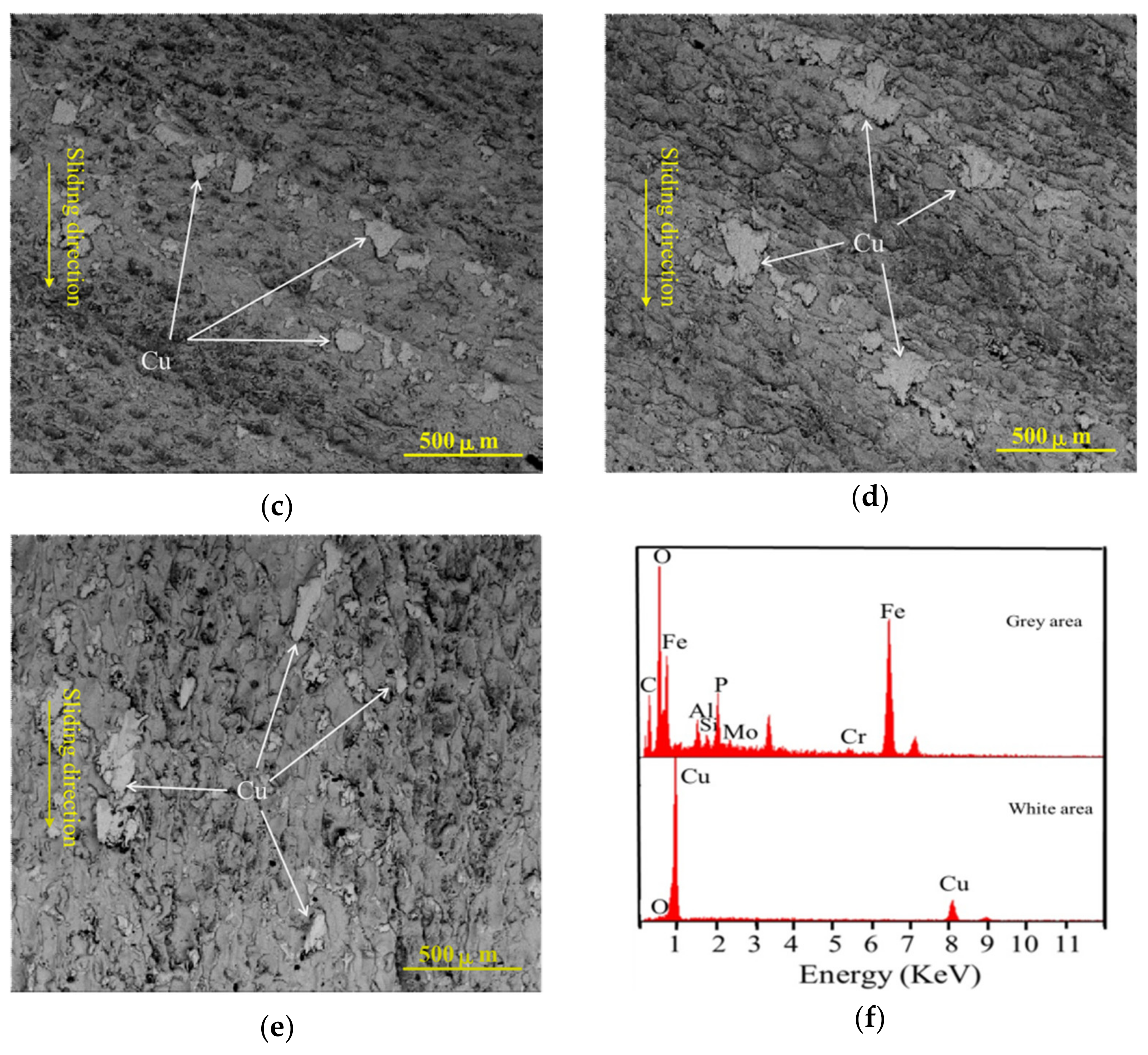
3.2. Worn Surface of the Tribo-Pairs

Figure 5a–e shows typical SEM images on the worn surfaces of the 38CrMoAl steel discs after working under different loads. As is seen, two areas with different colors (grey and white) can be observed on the surface of 38CrMoAl steel discs. After examining their compositions by EDX analysis (see Figure 5f), it was revealed that the grey area consisted of mainly iron, which is the steel matrix, while the white one was primarily composed of copper, which is stemming from the adhesion of wear debris and direction migration of copper from the pin to disc. This result is consistent with the observation on the migration of copper from the pin to the steel disc in last section. Moreover, judging from the morphology of most copper-contained stuffs (see Figure 5a–e), it seems that many of them are filling into the surface of the grey matrix (38CrMoAl steel) and the amount of the fillings increases with the increase of load, which are characteristic of wear debris. Specifically, when the applied load is low (less than 45 N), the rough pits on the surface of the 38CrMoAl steel disc are only partially filled with the wear debris (within the range of wear scars). However, after working under a heavy load (for example, 55 N), the distribution of the copper-based wear debris becomes quite uniform, spreading over the whole steel surface (see Figure 5e), implying that the pits are filled more fully.
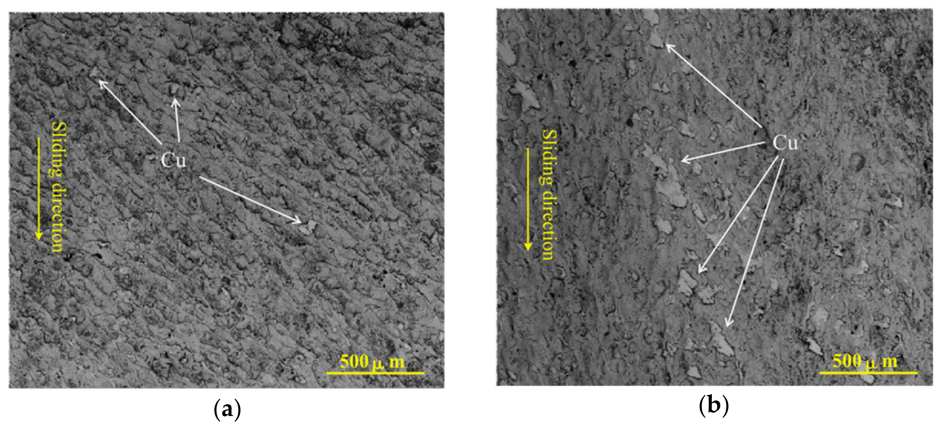
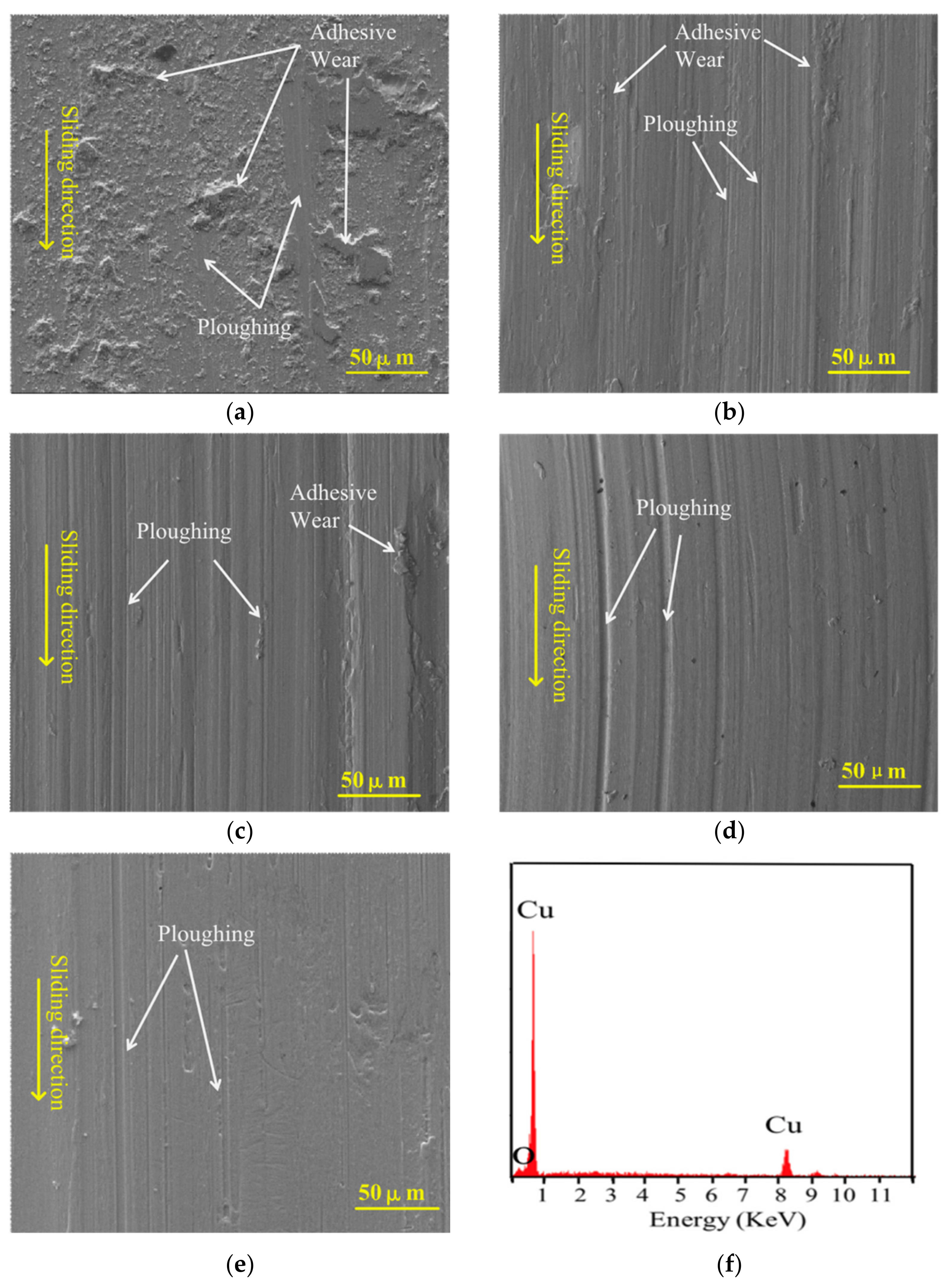
Figure 6a–e displays typical SEM images on the worn surfaces of the Qbe-2 beryllium bronze pins after working under different loads. As is seen, only one color can be identified over the SEM images, although there are different degrees of adhesion on the worn surface of the pins. EDX analysis (Figure 6f) revealed that both the homogeneous surface and the adhesion on the surface are composed mainly of copper without the presence of iron. Specifically, after working under 15 N, lots of small wear debris are attached onto the worn surface of the pin, indicating that adhesive wear might be its main wear mechanism, although ploughing is also presented (Figure 6a). However, the adhesion of wear debris diminishes and the grooves become deeper with the increase of load (see Figure 6a–e).
The following reasons may be responsible for these phenomena. Firstly, the contact peaks are pressed into the surface of the tribo-pair more deeply as the load increases. Simultaneously, due to the friction heat generated during the sliding process, the contact surface will be softened. Resultantly, it will be easier to produce wide and deep grooves on the surface of copper pin due to its lower hardness and the easier cutting of its surface by the asperities. On the other hand, from the EDX analysis results that the adhesions are composed of Cu and O, it can be induced that oxidation reaction may occur during friction process. The friction oxides can play a protective role for the surface of tribo-pair, thus reducing the wear of the tribo-pair, especially for the copper pin [19]. Meanwhile, due to the lubrication by the copper oxides, it is not easy for the copper debris to adhere onto the contact surface. In such case, less amount of wear debris will adhere to the surface of the tribo-pair.
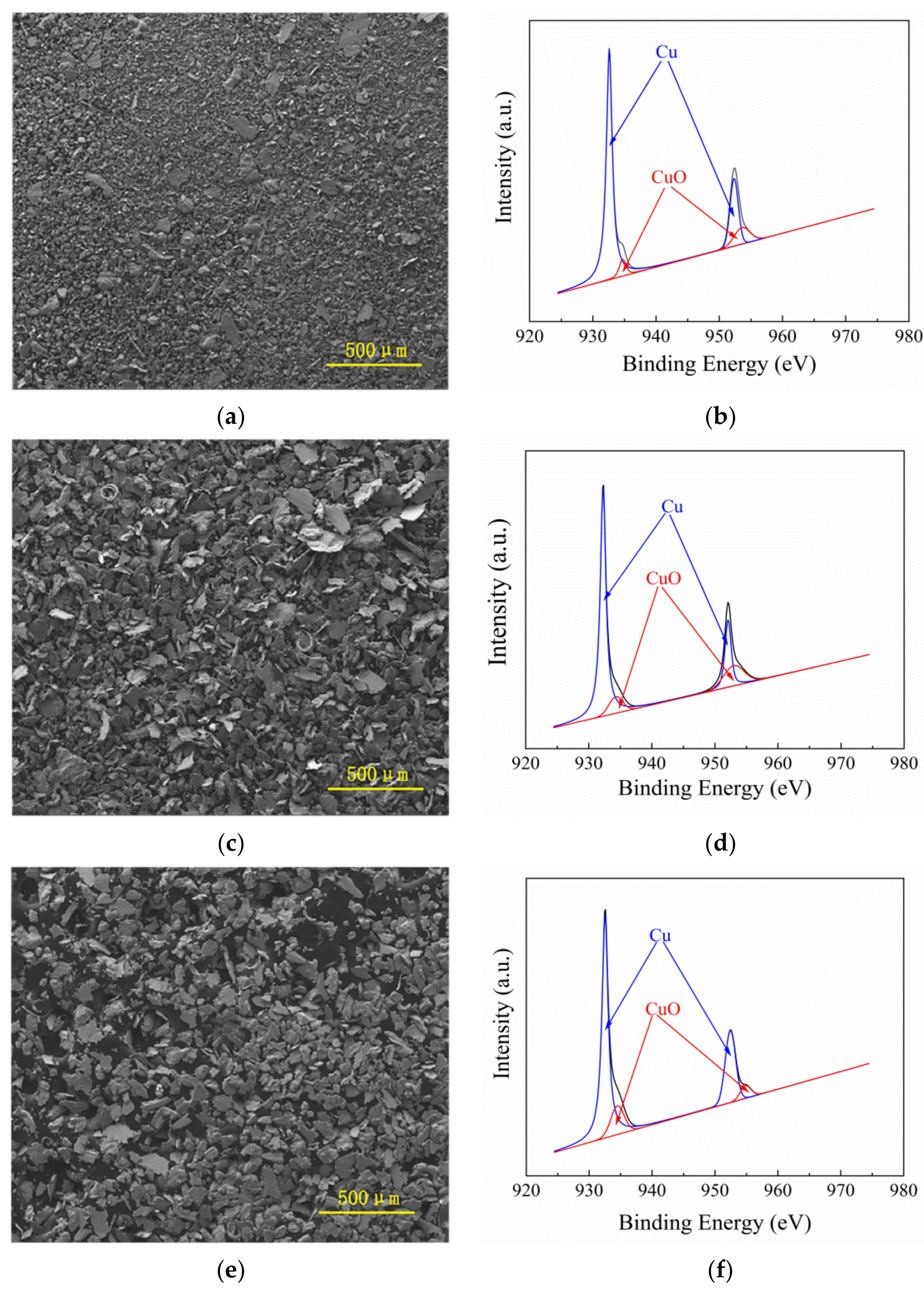
In order to further detect the composition and structure of the wear debris, SEM and XPS analyses were carried out. 
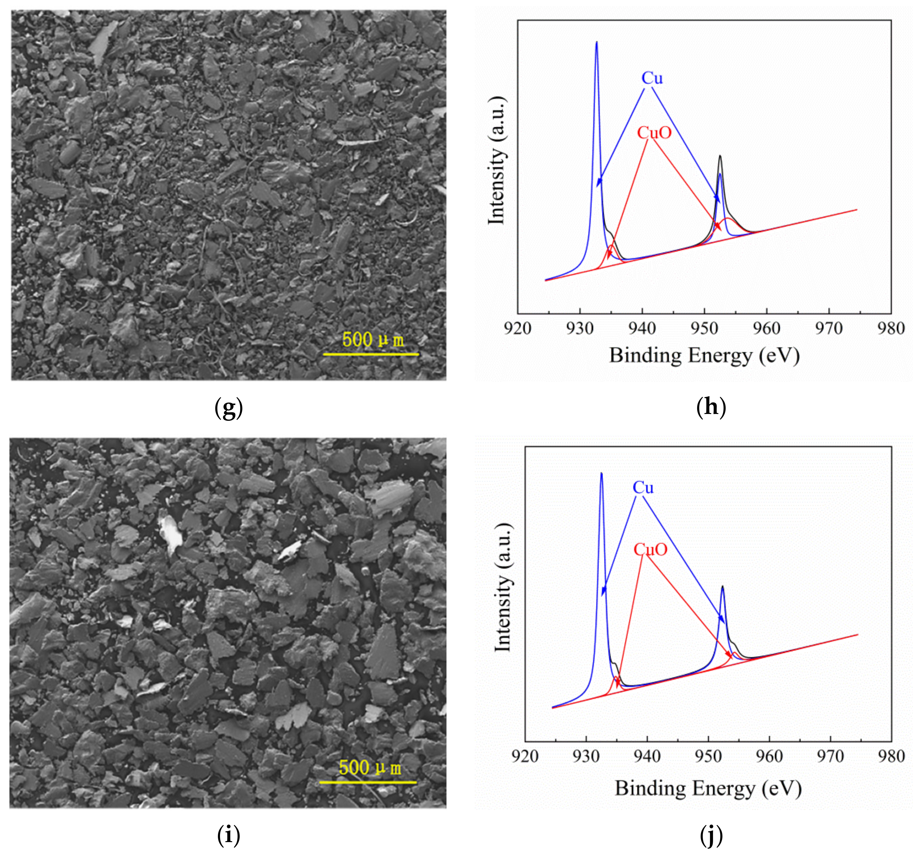
Figure 7 shows typical SEM images and corresponding XPS results on the worn-out debris at different loads. It can be seen that the size of the debris increases with the increase of load. EDX analysis and XPS surveying spectra show that only Cu and O could be detected in the wear debris without Fe, revealing that the material removal mainly occurs on the soft Qbe-2 beryllium bronze pins. In other word, the wear debris is originating from the soft copper pins. In particular, as can be seen in the high-resolution XPS spectra of copper shown in Figure 7, the recorded spectra of Cu 2p3/2 could be fitted into four peaks: the Cu0 metal peaks at 932.61 and 952.45 eV, as well the peaks of Cu2+ oxides at 933.3 and 953.7 eV [20,21], respectively. This result indicates that the wear debris mainly exists in the form of Cu and CuO.
Moreover, the debris is of small particles after working under a low load of 15 N, which is mainly because the load is not enough to crush the debris and thus the debris continuously rolls on the friction surface and many of them finally adheres to the copper surface (see Figure 6a) or fill in the pits of steel disc (see Figure 5a). This phenomenon also explains the large fluctuation of its friction coefficient at period 2. However, a larger number of asperities will fall off under the action of shear force with the increase of load. In particular, due to the friction heat generated during the friction under heavy load, the wear debris will be softened on the contact surface, and the larger compressive stress will make it repeatedly squeezed there, finally forming a larger size of flat wear debris (flakes) by repeating extruding.

3.3. Mechanism on the Friction and Wear
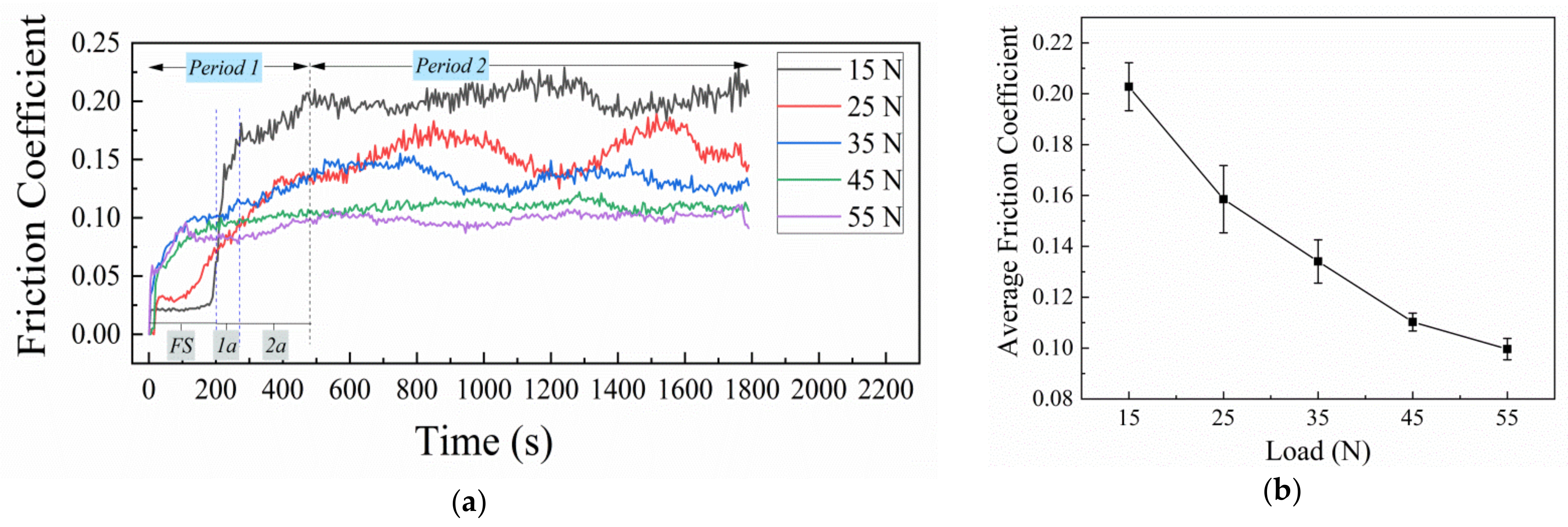
As shown in Figure 3a, the friction process can be divided into running-in period (period 1) and stable period (period 2) [22]. And according to the variation of friction coefficient, the running-in period can be further divided into two small stages, namely sharply increasing stage and slowly increasing stage.
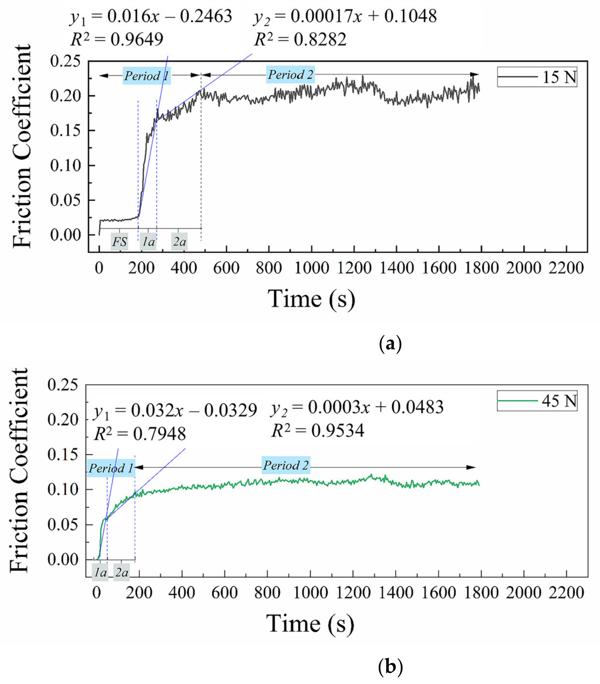
For the sample working under a low load of 15 N, the slope of friction coefficient in stage 1a is 0.0016, while that in stage 1b is 0.00017 (Figure 8a). That is, in this case, the increase of friction coefficient does not have a relationship of positive proportion with the wear duration. This phenomenon can be explained by the process of establishing a stable contact interface. Before the start of the tests, there are many asperities on the contact surface. The actual contact of the tribo-pair under load is the contact between the asperities of the copper pin and steel disc. When the tribo-pair works, because the hardness of Qbe-2 beryllium bronze is lower than that of the 38CrMoAl steel, the asperity on the Qbe-2 beryllium bronze pin surface is quickly removed. During this process, the contact surface interacts with asperities, and the friction coefficient rises rapidly (stage 1a). As the friction and wear proceed, the surface roughness of the Qbe-2 beryllium bronze pin and 38CrMoAlA steel disc decrease, which thus enters stage 1b. During this stage, the contact surface runs less violently [16]. With the removal of asperities and the embedding of wear debris on the surface of tribo-pair, the friction coefficient finally reaches period 2.
The running-in period will be gradually shortened as the load increases, because high pressure will accelerate the spalling of the asperities [16]. For example, when working under 45 N, the slope of the friction coefficient in stage 1a is 0.0032, while that in stage 1b is 0.0003 (see Figure 8b). At this stage, due to the heavy load, the removal of the asperities and the filling of wear debris into the surface pits of the tribo-pair will be more rapid, thus corresponding to a large slope of the friction coefficient and short running-in period. As the contact surface becomes smooth, the friction process reaches period 2. During this period, the average friction coefficient is approximately 0.105, which fluctuates in very small range.
As shown in Figure 3b, the average friction coefficient decreases with the increase of load, which can be explained from three aspects. With the increase of load, due to the friction, the steel surface will be more easily deformed. Compared with its initial morphology, the surface roughness decreases (see Figure 9). As a result, the actual contact area increases. At the same time, a part of the debris particles generated during the friction process will fill into the rough pits on the surface of the 38CrMoAl steel disc (see Figure 5b–e), which further increases the actual contact area of the tribo-pair due to the reduction of surface roughness, thus reducing the contact load per unit area. Moreover, the amount of material embedded on the steel surface is positively proportional to the applied load (see Figure 5b–e). With the increase of load, the tribo-pair changes from steel-copper friction to steel-copper friction together with copper-copper friction, and the copper-based materials have good self-lubrication performance. In addition, the existence of friction heat will accelerate the oxidation reaction of copper, and the generation of copper oxides plays an important role in reducing friction and lubrication of the present copper-steel tribo-pair [23]. In summary, the average friction coefficient decreases due to the interaction of the three factors.
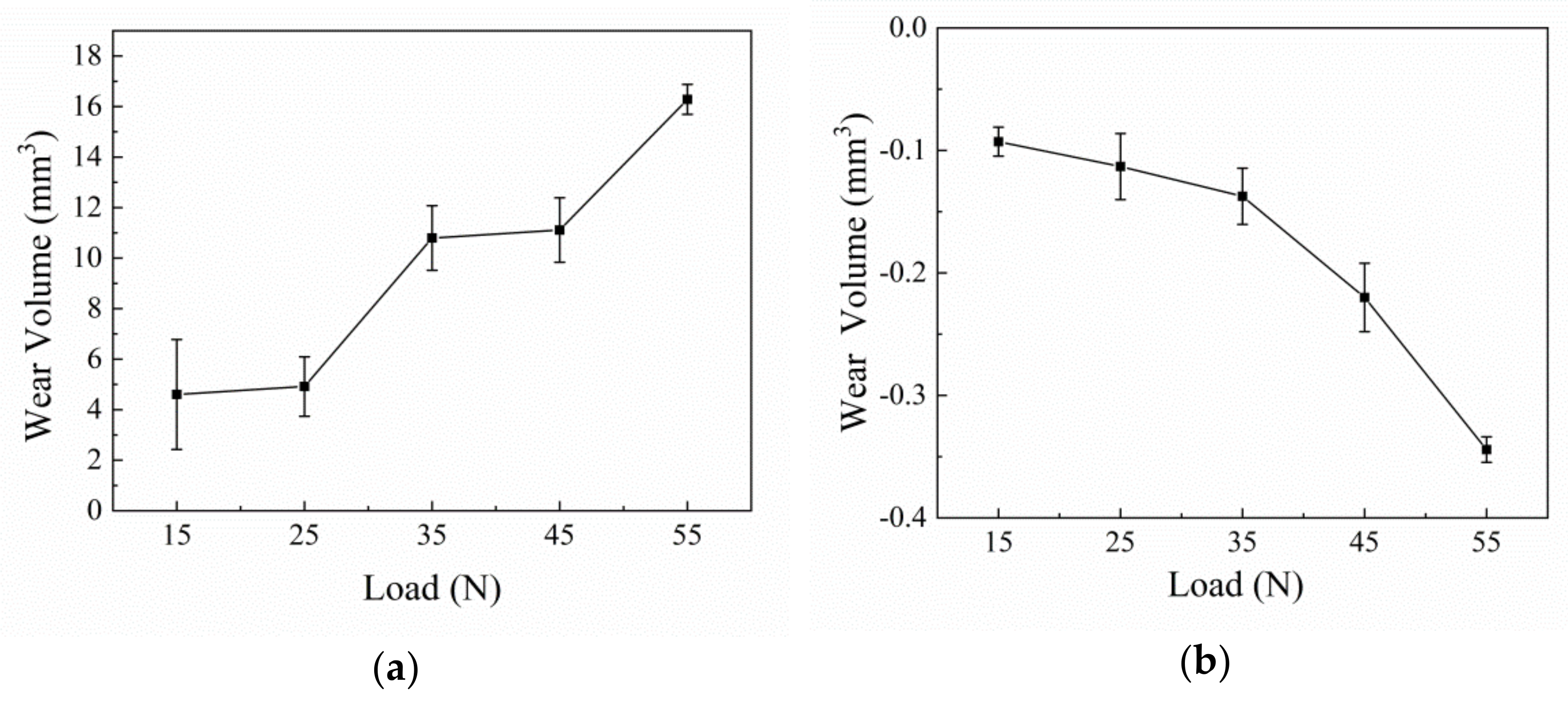
As shown in Figure 4a, the wear volume of the Qbe-2 beryllium bronze pins increases with the load. However, the volume change of the 38CrMoAl steel discs is small (Figure 4b), and the overall mass of the discs increases. For the Qbe-2 beryllium bronze pin working under 15 N, such a low load will produce a small shear force on the asperities on the contact surface, resulting in the formation of small debris particles (see Figure 7a), and the amount of the wear debris is very less, because a part of debris adheres to the copper surface (see Figure 6a). Resultantly, the wear volume of the copper pin is very small. However, with the increase of load, the asperities on the steel disc will be pressed into the copper surface more deeply, and the instantaneously increased temperature on the asperities will lead to the softening of the materials due to the generation of friction heat. Thus, a large amount of copper will fall off with the ploughing action of the asperities on the steel disc, and the actual contact area will increase with the continuous grinding of the asperities. The ploughing effect of the rough surface of 38CrMoAl steel disc on the copper contact surface will also cause the wear debris on copper surface to fall off, finally leading to the increase in wear volume of the copper pins (see Figure 4a). Although the oxidation effect produced by friction heat also plays a role in reducing the wear of the tribo-pair, ploughing is still the main factor for the removal of copper pin, because it is impossible to form a complete oxidation protection film over the surface of copper pin.
In addition, as shown in Figure 3, there is a large difference in the friction coefficient variation during the running-in period while different loads are applied. When the load is low, there is a short-time stable stage. With increasing load, the first, short-time stable stage is gradually shortened. When the load is greater than 35 N, such false stable stage completely disappears.
Aiming at explaining the false stability in the initial friction process establishment stage at 15 N, Figure 10 compares the SEM image on the surface morphology of the copper pin sample prepared just when the false stable stage is finished with that of the sample after the real stable period (period 2) is established. As is seen, the friction mechanism between the false stable stage and the real stable period 2 is significantly different. In Figure 10a, a lot of deep furrows without debris adhesion on the surface of the copper pin could be observed, indicating that the wear mechanism at the false stable stage is mainly ploughing instead of adhesive wear. However, when the real stable period 2 was established, lots of wear debris could be observed on the surface of copper pin almost without ploughing (see Figure 10b). Moreover, during the false stable stage, the material removal is not serious because of the lower load and slower rise of the temperature. At the very beginning of the friction (in the false stable stage), the ploughing happens because the asperities on the steel disc surface directly contact with those on the copper pin, and the steel can even press into the surface of copper pin surface due to its higher hardness. In this stage, no wear debris was produced. With the proceeding of the test, the asperities on the copper pin surface begin to fall off, and thus wear debris is generated. As a result, the friction coefficient increases, and then the running-in process occurs.
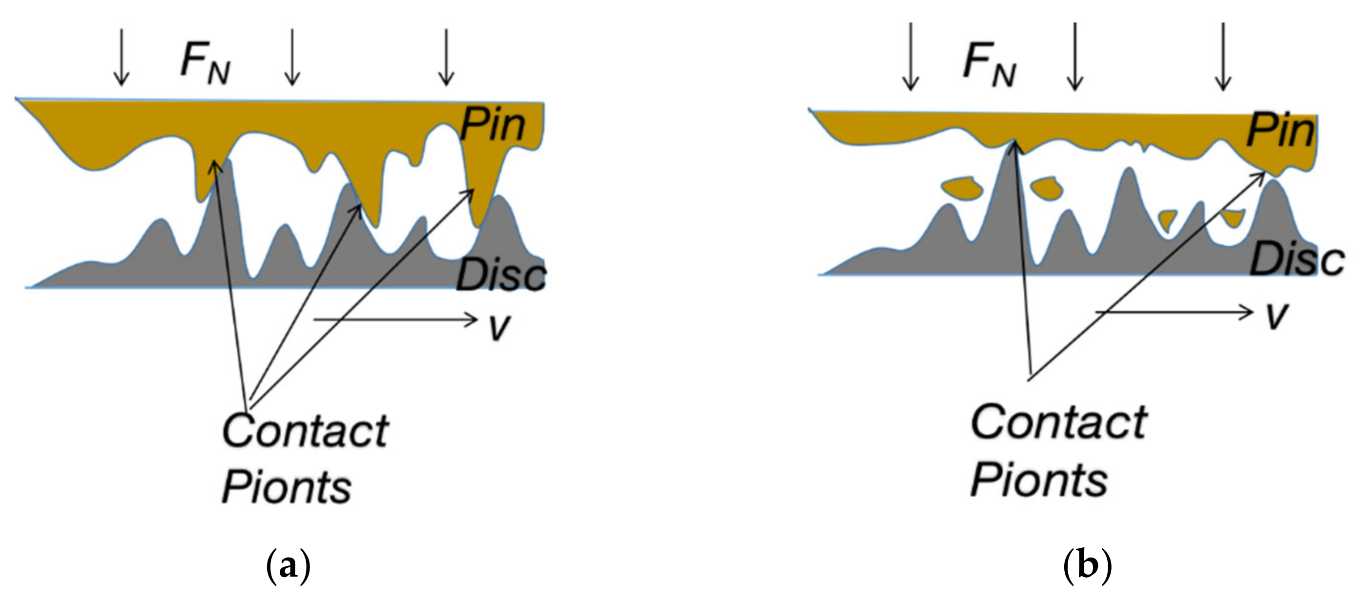
Figure 11 schematically summaries the process of establishing the stable state of friction coefficient under the low load of 15 N. Due to the existence of a large number of asperities on the surfaces of the tribo-pair at the initial stage, under the action of load, the actual contact area is higher than the surface area of tribo-pair because their asperities may contact with each other in a ratcheting way, which will result in a temporally low friction coefficient (see Figure 11a). And because Qbe-2 beryllium bronze has a lower hardness than 38CrMoAl steel, it will be ploughed with deep grooves by the asperities of steel (see Figure 10a). In this stage, the surface of the Qbe-2 beryllium bronze pin will be deformed greatly, but no debris is produced (Figure 11b). Thus the main wear mechanism is ploughing, and the tribo-pair keeps stable temporally at a lower friction coefficient. That is, it is in the so-called false stable stage. With the friction proceeding, the asperities on the surface of the Qbe-2 beryllium bronze pin began to fall off (Figure 11c), forming wear debris that will roll on the contact surface. However, because the load was low, which is not enough to crush the debris, the adhesion of the wear debris to the pin surface would accelerate the establishment of the running-in period (period 1). At present, the friction coefficient begins to rise due to the reduction of the actual contact area caused by the falling-off of the asperities (in stages 1a and 1b). After a period of running-in, the tribo-pair enters the stable state into the period 2 (Figure 11d). In this state, a large amount of wear debris will adhere to or freeze on the contact surface (see Figure 6a), resulting in the large fluctuation of the friction coefficient.
However, under a heavy load (for example, 45 N), the tribo-pair suffers from significantly different wear mechanism from that under the low load of 15 N. Figure 12 schematically presents the process of establishing the stable state for the friction coefficient under the heavy load of 45 N. Firstly, the initial stage is still the contact between the asperities (Figure 12a). However, due to the high load, the early running-in process is very short and the friction coefficient rises quickly with the rapid removal of the asperities on the softer counterpart (copper pin here) of the tribo-pair (Figure 12b). With the increase of load, the temperature rises due to the friction heat, and the resultant wear debris particles are easily squeezed into flakes, combining together and/or filling into the rough pits on the surface of steel disc. As a result, the running-in period is about to end (Figure 12c). After finally entering the stable period, the copper pin surface is ploughed by the asperities of the steel to produce the furrows, while the steel surface is deformed and a large amount of wear debris is embedded, resulting in a gradual flattening surface, where the friction coefficient is low with small fluctuation in the final stable period (Figure 12d).
Considering the simulated tribo-pair in this work will be used in the pneumatic downhole tools, the failure of the tribo-pair should be examined in the actual working conditions, such as the effective working time based on their wear rate. The results in this work suggest that although the wear loss is relatively small when the load is low, there exist a long running-in period, relatively large surface roughness, serious adhesion of debris to the tribo-pair and violently fluctuated friction coefficient. So, the working condition with low load is not really suitable for such pneumatic downhole tools. Under the conditions of relatively heavy load (for example 45 N in this work), although the wear loss may be somewhat large, the stable friction period can be promptly established and the surface of tribo-pair can become smooth in a short time. Resultantly, the final friction coefficient becomes low and stable swiftly, which will reduce the friction fluctuation of the tool and enable the tool work more stably. In fact, in such case, it is possible to extend the lifetime of the tribo-pair in pneumatic downhole tools to a great extent by optimizing the working conditions that the tribo-pair reaches stable more quickly under moderate load and the wear rate of the tribo-pair is smaller. In addition, in the present copper-iron tribo-pair, the material removal happens mainly on the soft copper, which can effectively reduce the worn-out of the steel, extending the service life of the tool. In practical application, through the introduction of copper, it can achieve the purpose of improving the service life of the tool. In short, compared with the traditional steel−steel and even copper−steel tribo−pairs, the performance of the present Qbe−2 beryllium bronze against 38CrMoAl steel tribo−pair has been greatly improved (see Table 5). Thus the present work will provide a solid support for systematically designing the tribo−pairs in pneumatic downhole tools under practical working conditions in drilling environment [24].

4. Conclusions

Pin−on-disc tests with Qbe-2 beryllium bronze pin against 38CrMoAlA steel disc were carried out to simulate the friction and wear behavior of the copper-iron tribo-pair rotating seal in pneumatic downhole tools.
(1) The variation of friction coefficient can be divided into two periods: running-in period and stable period. The running-in period can be further divided into sharply increasing stage and slowly increasing stage. In the running-in period, the friction coefficient gradually increases to the maximum due to the falling-off of the asperities. However, with the gradual spalling of the asperities, the rising rate of the friction coefficient slows down. When working under a low load (15 N), the friction coefficient presents a false stability and fluctuates violently in the stable period. Under a heavy load (no lower than 45 N), the friction coefficient tends to become stable quickly and fluctuates slightly.
(2) The false stability is caused by ploughing the surface of soft copper pin in the friction process. However, the final stable period is generated by the adhesion of the wear debris onto the tribo-pair. Under a low load, the wear mechanism changed from mainly ploughing to dominantly adhesive wear as the load increases. The formation of wear debris and their adhesion to the copper surface are the main reasons for the change of wear mechanism in false and final stable state of the friction coefficient. And the deformation of steel surface and the filled copper debris on it are the main reasons for the formation of specific wear mechanism (ploughing) under heavy load.
(3) Through introducing copper alloys between the stator and rotor as rotating seals in pneumatic downhole tools and by optimizing stable working conditions for the tribo-pairs with lower wear rate under moderate load (45 N here), it can extend the service life of the tribo-pairs in pneumatic downhole tools. In addition, the material removal between the copper-iron tribo-pairs mainly occurs on the copper party, indicating that in practical applications, the life of the drilling tools can be extended through replacing the copper piece. The present work will provide a solid support for systematically designing the tribo-pairs in pneumatic downhole tools under practical working conditions in drilling environment.

Author Contributions

C.L.: literature surveying, drawing of figures and tables, design of experiments, data collection and analysis, writing of original manuscript; Y.W.: literature surveying, design of the experiments, revision and finalizing of the manuscript and supervision of the project; K.Z.: partial data collection and analysis, drawing of partial figures and tables, revision and finalizing of the manuscript; Z.P.: design of the experiments, revision and finalizing of the manuscript, and supervision of the project. All authors have read and agreed to the published version of the manuscript.

Funding

This research was funded by [National Key R&D Program of China] grant number [2018YFC1802404], [National Natural Science Foundation of China] grant number [41872180] and [Excellent Youth Foundation in China University of Geosciences from the Fundamental Research Funds for the Central Universities] grant number [No. 292018093].

Data Availability Statement

Not applicable.

Conflicts of Interest

The authors declare no conflict of interest.

References

  1. Han, G.; Bruno, M.S.; Dusseault, M.B. 3D simulation of rock breakage with air hammers in gas-well drilling. Spe Gas Technol. Symposium 2006. [Google Scholar] [CrossRef]
  2. Ryan, G.; Tibor, R.; Steve, B.; Julio, C.; Eduardo, C.; Cote, B. Hammer motor smashes its way to speedy success in Brazil. In Proceedings of the IADC/SPE Drilling Conference and Exhibition, San Diego, CA, USA, 6–8 March 2012. [Google Scholar]
  3. Weller, T.F.; Baum, G.A.; Muncy, W.H. Diamond-enhanced hammer bits reduce costs-per-foot and directional problems in Southwestern Pennsylvania Oriskany Wells. In Proceedings of the SPE Eastern Regional Meeting, Morgantown, WV, USA, 24–27 October 1989. [Google Scholar]
  4. So, H. Characteristics of wear results tested by pin-on-disc at moderate to high spe. Tribol. Int. 1996, 29, 415–423. [Google Scholar] [CrossRef]
  5. So, H.; Chen, H.M.; Chen, L.W. Extrusion wear and transition of wear mechanisms of steel. Wear 2008, 265, 142–1148. [Google Scholar] [CrossRef]
  6. Mahdavian, S.M.; Mai, Y.W. Further study in friction, metallic transfer and wear debris of sliding surface. Wear 1984, 95, 35–44. [Google Scholar] [CrossRef]
  7. Ferreira, R.O.; Galvani, G.B.; Tertuliano, I.S.; Rodrigues, A.C.P.; Azevedo, C.R.F. Characterization and evolution of the coefficient of friction during pin on disc tribotest: Comparison between C10200 Cu, AA6082-T6 Al and C36000 brass pins under varying normal loads. Tribol. Int. 2019, 138, 403–414. [Google Scholar] [CrossRef]
  8. Lu, H.L.; Zhang, P.P.; Ren, S.S.; Guo, J.D.; Li, X.; Dong, G.N. The preparation of polytrifluorochloroethylene (PCTFE) micro-particles and application on treating bearing steel surfaces to improve the lubrication effect for copper-graphite (Cu/C). Appl. Surf. Sci. 2018, 427, 1242–1247. [Google Scholar] [CrossRef]
  9. Sosnovskii, S.V.; Sei’kin, V.P. Effect of transfer medium on wear rate of groove seals of centrifugal pumps. J. Frict. Wear 2013, 34, 134–136. [Google Scholar] [CrossRef]
  10. Zhao, W.G.; Zhang, G.Y.; Dong, G.N. Friction and wear behavior of different seal materials under water-lubricated conditions. Friction 2020. [Google Scholar] [CrossRef]
  11. Xue, W.H.; Gao, S.Y.; Duan, D.L.; Zheng, H.L.; Li, S. Investigation and simulation of the shear lip phenomenon observed in a high-speed abradable seal for use in aero-engines. Wear 2017, 386–387, 195–203. [Google Scholar] [CrossRef]
  12. Barros, L.Y.; Poletto, J.C.; Neis, P.D.; Ferretra, N.F.; Pereira, C.H.S. Influence of copper on automotive brake performance. Wear 2019, 426, 741–749. [Google Scholar] [CrossRef]
  13. Jayashree, P.; Federici, M.; Bresciani, L.; Turani, S.; Sicigliano, R.; Straffelini, G. Effect of steel counterface on the dry sliding behaviour of a Cu-based metal matrix composite. Tribol. Lett. 2018, 66, 1–14. [Google Scholar] [CrossRef]
  14. Jayashree, P.; Turani, S.; Straffelini, G. Effect of testing conditions on the dry sliding behavior of a Cu-Based refractory composite material. Tribol. Int. 2019, 140, 105850. [Google Scholar] [CrossRef]
  15. Jayashree, P.; Bortolotti, M.; Turani, S.; Straffelini, G. High-temperature tribo-oxidative wear of a Cu-based metal-matrix composite dry sliding against heat-treated steel. Tribol. Lett. 2019, 67, 1–12. [Google Scholar] [CrossRef]
  16. Wu, J.; Ma, B.; Li, H.; Stanciulescu, I. The running-in micro-mechanism and efficient work conditions of Cu-based friction material against 65Mn steel. Exp. Tech. 2019, 43, 667–676. [Google Scholar] [CrossRef]
  17. Farokhian, G.H.; Salehnasab, B.; Zat, A.H. Influence of WC-20Co-1Ni coating by HVOF on lifespan of the downhole drilling motors. Surf. Eng. 2017, 34, 771–782. [Google Scholar] [CrossRef]
  18. Zhang, Z.Q.; Xiang, Y.; Zhao, W.W. Exploring wear detection method for special drilling parts in liquid media. Int. J. Refract. Met. Hard Mater. 2016, 61, 249–258. [Google Scholar] [CrossRef]
  19. Wang, Y.; Zhang, L.; Zhai, H.F. Tribological behavior of Cu-15Ni-8Sn/graphite under sea water, distilled water and dry-sliding conditions. J. Cent. South Univ. 2019, 26, 2623–2633. [Google Scholar] [CrossRef]
  20. Barreca, D.; Gasparotto, A.; Tondello, E. CVD Cu2O and CuO nanosystems characterized by XPS. Surface Sci. Spectra 2007, 14, 41–51. [Google Scholar] [CrossRef]
  21. Sun, Y.X.; Song, C.; Liu, Z.L.; Li, J.W.; Wang, L.; Sun, C.; Zhang, Y.Z. Tribological and conductive behavior of Cu/Cu rolling current-carrying pairs in a water environment. Tribol. Int. 2020, 143, 106055. [Google Scholar] [CrossRef]
  22. Zhang, K.; Wang, D.; Wang, Z.; Li, Y.; Zhou, Q.; Liu, B.L.; Wang, Z. Effect of Ni content and maceration metal on the microstructure and properties of WC based diamond composites. Int. J. Refract. Met. Hard Mater. 2020, 88, 105196. [Google Scholar] [CrossRef]
  23. Asempah, I.; Xu, J.H.; Yu, L.H.; Luo, H.; Liu, J.L.; Yu, D.; Ding, N. The role of copper incorporation on the microstructure, mechanical and tribological properties of TiBN-Cu films by reactive magnetron sputtering. J. Alloys Compd. 2019, 801, 112–122. [Google Scholar] [CrossRef]
  24. Zhang, K.; Wang, D.; Wang, Z.; Guo, Y. Material properties and tool performance of PCD reinforced WC matrix composites for hardbanding applications. Int. J. Refract. Met. Hard Mater. 2015, 51, 146–152. [Google Scholar] [CrossRef]
Figure 1. Schematic diagram of the designed pneumatic downhole motor with copper-steel seal.
Metals 11 00459 g001
Figure 2. Tribological set-up and the tribo-pair. (a) Test rig; (b) schematically 3D diagram of the tribo-pair; (c) 2D surface profile of typical upper specimen; and (d,e) photographs of the pin and disc, respectively.
Metals 11 00459 g002
Figure 3. Friction coefficients between the designed copper-iron tribo-pair working under different loads: (a) variation of the friction coefficients with wear duration; and (b) the average friction coefficients during the stable period.
Metals 11 00459 g003
Figure 4. Wear volumes of the present copper-iron tribo-pair working under different loads: (a) Qbe-2 beryllium bronze pin; and (b) 38CrMoAl steel disc.
Metals 11 00459 g004
Figure 5. SEM images on the worn surfaces of 38CrMoAlA steel discs working under different loads: (a) 15 N; (b) 25 N; (c) 35 N; (d) 45 N; (e) 55 N. The arrows in the pictures indicate the sliding direction. (f) EDX analysis results on the grey area and the fillings (white area).
Metals 11 00459 g005aMetals 11 00459 g005b
Figure 6. SEM images on the worn surfaces of Qbe-2 beryllium bronze pins working under different loads: (a) 15 N; (b) 25 N; (c) 35 N; (d) 45 N; (e) 55 N. The arrows in the pictures indicate the sliding direction. (f) EDX analysis on the adhesion.
Metals 11 00459 g006
Figure 7. SEM images of the worn-out debris produced under different loads and the corresponding XPS high-resolution spectra of copper: (a,b) 15 N; (c,d) 25 N; (e,f) 35 N; (g,h) 45 N; (i,j) 55 N.
Metals 11 00459 g007aMetals 11 00459 g007b
Figure 8. Analysis on the instantaneous friction coefficient slopes for the tribo-pair working under different loads: (a) 15 N; (b) 45 N.
Metals 11 00459 g008
Figure 9. Three-dimensional surface topography of the steel discs after working under different loads: (a) the original surface; (b) a light load of 15 N; (c) a heavy load of 45 N.
Metals 11 00459 g009
Figure 10. SEM images on the worn surface of the copper pin after working under a load of 15 N for (a) 180 s; and (b) 1800 s, respectively.
Metals 11 00459 g010
Figure 11. Schematic diagram of establishing the stable process for the friction coefficient under a low load of 15 N: (a) establishment contact; (b) ploughing; (c) generation of early wear debris; and (d) adhesion of wear debris.
Metals 11 00459 g011
Figure 12. Schematic diagram of establishing the stable process for the friction coefficient under a heavy load of 45 N: (a) establishment contact; (b) early running-in period; (c) later running-in period; and (d) stable period.
Metals 11 00459 g012aMetals 11 00459 g012b
Table 1. Chemical composition of Qbe-2 beryllium bronze (wt.%).
BeSiCrFePbNiCuImpurity
1.8–2.1≤0.151.35–1.65≤0.15≤0.0050.2–0.4bal.≤0.5
Table 2. Chemical composition of 38CrMoAl steel (wt.%).
CSiMnSCrAlMoPNiCu
0.35–0.420.20–0.450.30–0.60≤0.0351.35–1.650.70–1.100.15–0.25≤0.035≤0.030≤0.030
Table 3. Main mechanical properties of the friction materials.
Mechanical PropertiesQbe-2 Beryllium Bronze38CrMoAl Steel
Tensile strength σb (MPa)≥1000≥980
Yield strength σs (MPa)≥880≥835
Elongation δ (%)≥17≥14
Reduction of area ψ (%)≥50≥50
Impact Energy AKU (J)≥80≥71
Impact toughness (J/cm2)≥88≥88
Density (g/cm3)8.77.85
Hardness (HRB)79.3103.1
Table 4. The set test parameters for the dry sliding pin-on-disc simulation.
Program123456
Load/N152535455515
Speed/(rpm)300300300300300300
Time(s)18001800180018001800180
Table 5. Comparison on the performance of the present copper-steel tribo-pair with the results in literature.
Tribo-PairTesting
Conditions *
Wear
Mechanism
Friction
Coefficient
Wear Rate (m/m) **
AISI1045-die steel [5]4 m/s–5.5 MPaextrusion0.44–0.87.2 × 10−6–3.3 × 10⁻⁸
AISI1045−die steel [5]2.5 m/s–3.3 MPaoxidation0.2–0.42.2 × 10−8
AISI104−die steel [5]4 m/s–4.4 MPaoxidation and extrusion0.4–0.54.4 × 10−6–3 × 10⁻⁷
Copper-based composite-martensitic steel [13]1.57 m/s–1 MPalow−sliding speed oxidation0.4–0.5no data
Copper-steel (in this work)300 rpm–45 N (2.8 m/s
−2.29 MPa)
ploughing0.10.016 mm3/m (on the copper party)
* m/s: sliding speed; MPa: load. ** m/m: wear depth per meter of sliding distance.
Publisher’s Note: MDPI stays neutral with regard to jurisdictional claims in published maps and institutional affiliations.

