Abstract
The journey of production tools in cold working, hot working, and injection molding from rapid tooling to additive manufacturing (AM) by laser-based powder bed fusion (L-PBF) is described. The current machines and their configurations, tool steel powder materials and their properties, and the L-PBF process parameters for these materials are specified. Examples of production tools designed for and made by L-PBF are described. Efficient design, i.e., high tooling efficiency and performance in operation, should be the primary target in tool design. Topology and lattice structure optimization provide additional benefits. Using efficient design, L-PBF exhibits the greatest potential for tooling in hot working and injection molding. L-PBF yields high tooling costs, but competitive total costs in hot working and injection molding. Larger object sizes that can be made by L-PBF, a larger number of powder metals that are designed for different tooling applications, lower feedstock and L-PBF processing costs, further L-PBF productivity improvement, improved surface roughness through L-PBF, and secured quality are some of the targets for the research and development in the future. A system view, e.g., plants with a high degree of automation and eventually with cyber-physically controlled smart L-PBF inclusive manufacturing systems, is also of great significance.
1. Introduction
To build objects by adding many very thin layers of material, layer on top of layer, has historically attracted some attention. The progress made during the past 40 years has, however, been the greatest and most profound.
Technologically, it was held that such a layer-by-layer manufacturing was the common denominator of (a) computer aided design (CAD), i.e., solid modelling, (b) enabling technologies, i.e., laser, ink-jet printers and motion control, and (c) traditional technologies, i.e., powder metallurgy, welding, extrusion, computerized or computer numerically controlled (CNC) machining, and lithography.
Industrially, rapid prototyping would enable a fast visualization and evaluation of the product design and a rapid tooling would shorten the time-critical toolmaking in the industrialization of new products (and thereby reduce the time to market).
Rapid tooling, particularly direct rapid tooling, through layer-by-layer toolmaking evolved in the middle of 1990s. Direct rapid tooling was defined as an industrial concept aimed at the realization of production tooling through layered manufacturing directly from CAD data files.
As far as layered manufacturing is concerned, several methods have been developed. Selective laser sintering (SLS), one of the methods that were developed initially, was launched in 1995. This method evolved to selective laser melting (SLM). In these methods, a thin layer of metal powder is sintered or melt. A steel powder based SLM machine was launched in 1999.
At the same, a similar technology, in which an electron beam is used instead of a laser beam, was developed for metallic materials. This paper is focused on metallic materials and SLM.
Now after two decades, the so-called layered manufacturing and SLM are standardized to additive manufacturing (AM) and laser-based powder bed fusion (L-PBF). The remarkable advances in AM and L-PBF in the past two decades have resulted in production tooling that is highly advanced both in design and performance.
This paper is an account of how production tools can be made today thanks to the scientific and technological advances during the past 20 years. To be brief, this account focuses on the “newness”. For instance, machining and heat treatment are not mentioned in this paper. (Machining is in many cases used to post-process a production tool made by L-PBF to improve its surface roughness).
This account comprises:
- A brief history of direct rapid tooling by SLS/SLM.
- A brief description of L-PBF.
- A brief account of applications and materials for production tooling.
- The L-PBF process parameters for these materials.
- The new tooling design ingredients, i.e., generative design and topology and lattice structure optimization, primarily as an amplifier of and important complement to L-PBF.
- Examples of tooling applications designed for and made by L-PBF. These examples, which are from cold and hot working and injection molding, illustrate the results of the advances made during the past 20 years and the yet greater future potential in toolmaking.
- Discussions including a future outlook and
- Conclusions.
The methodology used to create this review is described in Appendix A.
2. Direct Rapid Tooling by Selective Laser Sintering/Melting—Brief History as a Baseline
The process of building objects by adding many very thin layers of material, layer on top of layer, has historically had several names. Solid freeform fabrication (SFF) through layered manufacturing in order to accomplish rapid prototyping (RP) can trace its roots back to the 19th century, particularly the fields of topography and photosculpture [1,2].
Early SFF examples were proposed by Swainson in 1968, Ciraud in 1971, Kodama in 1981, and Herbert in 1982 [1]. After a few years, Hull invented the stereolithography machine (SLA) in 1986. This machine is considered to be the first 3D printer [2].
It was held that SFF was the common denominator of the following [1]:
- Computer aided design (CAD): Solid modelling.
- Enabling component technologies: Laser, ink-jet printers and motion control.
- Traditional technologies: Powdered metallurgy, welding, extrusion, CNC machining and lithography.
The various SFF building strategies and deposition/fusion processes included photolithography, laser fusion, lamination, extrusion, and ink-jet printing.
Product creation comprises chiefly product design/development and industrialization. Once the design is accepted, the realization of the production line, in particular the preparation of complex production tooling (tools, dies, and molds), is time-critical in the industrialization phase and has therefore a direct and strong influence on time-to-market. RP through SFF (or layered manufacturing), used to visualize and evaluate the results of product design (or development phase of a product), evolved in the middle of 1990s toward rapid tooling (RT). This extension was caused by the need to further reduce the time-to-market by shortening, not only the development phase, but also the industrialization phase of product creation [3,4,5,6].
RT was divided into non-direct RT and Direct RT (DRT):
- Non-direct RT: SFF techniques shortening the classical/traditional toolmaking methods, e.g., using SLA to make a pattern for investment casting, resin tooling, etc., [7]. SLA, FDM (fused material deposition), LOM (laminated object manufacturing), and SLS-P (P = polymers) were used to accomplish non-direct RT.
- DRT: techniques requiring no intermediate steps in the manufacture of tools. In other words, DRT was defined as an industrial concept aimed at the realization of production tooling directly from CAD data files, with the smallest possible process chain (number of operations). Its purpose was the manufacture of tools that can be used under normal production conditions, in terms of durability, accuracy and surface quality. LG (laser generation), SLS-M (M = metals), SLS-PM (selective laser sintering of polymer-coated metal powder), and 3DP (three-dimensional printing) were used to accomplish DRT [8,9,10].
The present paper is focused on DRT by SLS-M. As far as SLS-M is concerned, several parallel tracks were followed by different researchers. The research and development by Deckard and Beaman at the University of Texas in Austin, [11], resulted in Sinterstation 2000—the first proper commercial system for laser-sintering launched by DTM Corporation of Austin in December 1992 [12,13]. DTM used the Sintersation to laser-sinter a polymer-coated metal powder to form a green part, followed by a furnace process to remove the polymer, bond the metal matrix and infiltrate it with a secondary metal to remove the porosity [14]. This process was called “RapidTool” and commercially released at the end of 1995.
EOS GmbH of Munich collaborated with Electrolux Rapid Development (ERD) of Rusko, Finland, and Nyrhilä that were involved in the development of Direct Metal Laser Sintering (DMLS). ERD was focused on powder metallurgy development and Nyrhilä had invented a novel powder concept for pressureless metal sintering with very low shrinkage in 1989 [15]. This collaboration resulted in development and installation of the first commercial DMLS system, EOSINT M 250, in the summer of 1995 [12,13]. This opened up the first real commercial use of DMLS for rapid tooling [12].
This equipment was used in 1996 to make injecting molding tools. One of these tools (which comprised 11 parts) was laser-sintered in the nickel-bronze mixture (Ni-Bz) developed by ERD and infiltrated with high temperature epoxy resin within 45 h. After sanding, polishing, integrating the gating system and the ejectors, Electrolux assembled the mold and produced approximately 100 mobile phone housings in PC/ABS using standard parameters. An overall accuracy of ±0.1 mm was reached [10]. The same mold was traditionally made in aluminium.
The time from completed CAD data to producing the injected parts in series material took Electrolux four weeks and cost DM 30,000 (DM = Deutsche Mark). This was considered as a remarkable reduction in time and costs for manufacturing injection mold prototypes and small batches of components [10].
SLS-M attracted great attention and many studies were conducted to explore the possibilities, optimize the process and develop DRT further [16,17,18,19].
At the same time, the researchers and device/equipment manufacturers were aware of the shortcoming of the DRT techniques that were available in 1995. These techniques allowed only the fabrication of pre-series or short-run tools, could not yield sufficiently high properties for demanding tools, e.g., forging dies, and required time consuming post-sintering through infiltration.
Porosity, part shrinkage, and thermal and mechanical instability were some additional problems. The nickel-bronze mixture developed by Nyrhilä and ERD, [15], exhibited a near-zero shrinkage and minimal curl and warpage [10] when laser-sintered without any protecting gas. However, it was known that oxidation before, during and after sintering of other metal powders would result in lower yield strength, cracks etc., and must therefore be prevented. Parameters influencing the accuracy, such as laser scan speed, laser power, powder delivery, powder properties, powder compaction, post-processing, etc. should be tested, evaluated, and optimized [3,10].
Many research projects were carried out to remedy these shortcomings [12,13,20,21,22].
The successful efforts at Fraunhofer ILT to accomplish fully dense metal objects by complete melting (SLM) showed how the SLS process needed to be altered. For SLM, the chamber needed to be closed/shielded and flooded with an inert gas like argon so that the wetting properties of the melt were not reduced by formation of an oxide skin layer. The metal powder was, as wished, processed without any binder material and without any kind of pre-treatment. However, the particle shape must be spherical with a size in the range of 20–50 μm. To melt the powder particles completely, as shown in Figure 1, fundamental investigations of the physical interrelations between the process parameters and the behavior of the metal melt were carried out. Laser power, scan speed, hatch distance and layer thickness appeared to be interrelated and crucial for the processing results. The influence of scanning strategies and protection gas flow was determined. In addition, a special scanning strategy with a limited length of each scan vector had to be used to achieve a high density of the parts [20,22].
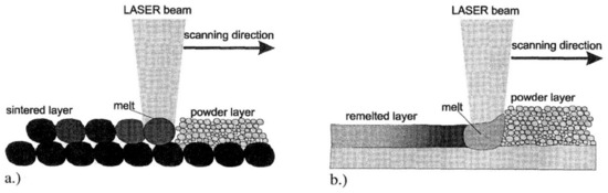
Figure 1.
Melting process of single component powder with a laser beam: (a) porous structure with SLS and (b) dense structure with SLM [22].
With this developed procedure, objects in stainless steel 316L, TiA16V4 and DIN 1.2343 (H11) were made with a density of 99%. Infiltration to improve density and strength was no longer necessary. Figure 2 shows a couple of tools made by the then newly developed SLM. The slider for a die casting tool made by SLM in DIN 1.2343, Figure 2a), was fitted into the conventionally made tool. 4800 housings in AlSi12 were produced in this tool at a casting temperature of 700 °C and a pressure of approx. 800 bar without any visible tool wear. The injection molding tool in Figure 2b) was made by SLM in stainless steel 316L. It took ca 4 h to make the core and ca 7 h to make the cavity. After SLM, the mold release surfaces had to be manually smoothed and the core and cavity had to be fitted into the mother tool. This tool was used to produce thermoplastic parts as well as rubber parts [22]. See also [23].
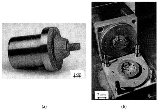
Figure 2.
Tools made by the then (1999) newly developed selective laser melting (SLM): (a) slider for a die casting tool made in 1.2343 and (b) injection molding tool made in 316L [22].
3. Laser-Based Powder Bed Fusion (L-PBF)
During the past 15 years, layered manufacturing has been subject to further research studies, standardization and industrialization. According to the developed standards, the technology is named Additive Manufacturing (AM). Laser-based powder Bed Fusion (L-PBF), formerly SLM (Figure 1b), is one of the seven AM basic process categories in the new standards [24,25,26,27]. For a detailed description of L-PBF, see [28,29,30,31,32].
Table 1 displays the features of the current (2020) machines for AM by L-PBF. This table, which is based on the machine makers specifications, show that the maximum object size that can be 3D-printed today is 600 × 600 × 600 mm3 (although the largest height is 850 mm in one of the other machines). This size has more than doubled compared to that in the 1995 machine for selective laser sintering. In addition to higher laser power, some of the current machines have more than one laser and therefore a much higher productivity.
Due to the complexity of L-PBF, the manufacturers of metal AM systems have developed sets of optimized processing conditions for some existing powder metals. The machine manufacturer sets the process parameters for one or some specific powder metals as the default values for additive manufacturing based on the customer preferences before machine delivery and installation, Table 2. The number of these powder metals is much larger than those in 1995. However, this number is still very small, compared to the number of existing materials made and used conventionally.

Table 1.
The features of the current L-PBF machines [33,34,35,36,37,38,39].
Table 1.
The features of the current L-PBF machines [33,34,35,36,37,38,39].
| Manufacturer | Model | Number and Type of Lasers | Laser Power (per Laser) (W) | Build Volume (l × w × h) (mm3) | Build Rate (cm3/hr) | Layer Thickness (μm) | Scan Speed (m/s) |
|---|---|---|---|---|---|---|---|
| 3D Systems | DMP Factory 500 Printer Module | 3 fiber | 500 | 500 × 500 × 500 1 | - | 2–200, Typical: 30, 60 & 90 | - |
| DMP Factory/Flex 350 | 1 fiber | 500 | 275 × 275 × 420 | - | 5–200, Typical: 30, 60 & 90 | - | |
| DMP Flex 100 | 1 fiber | 100 | 100 × 100 × 90 | - | 10–100 | - | |
| ProX DMP 300 | 1 fiber | 500 | 250 × 250 × 330 | - | 10–100, preset: 40 | - | |
| ProX DMP 200 | 1 fiber | 300 | 140 × 140 × 115 | - | 10–100, preset: 30 | - | |
| Additive Industries | MetalFAB1 | 1 to 4 Yb fiber | 500 | 420 × 420 × 400 | - | 20–100 | - |
| Concept Laser | X Line 2000R | 2 (cw) fibre | 1000 | 800 × 400 × 500 | - | - | - |
| M Line Factory | 4 fiber | 1000 | 500 × 500 × 400 | - | - | - | |
| M2 Multilaser | 2 (cw) fiber | 400 | 250 × 250 × 350 | - | - | - | |
| EOS | EOS M 400-4 | 4 Yb-fiber | 400 | 400 × 400 × 400 1 | 100 | 80 | 7 |
| EOS M 400 | 1 Yb-fiber | 400 | 400 × 400 × 400 1 | 50 | - | 7 | |
| EOS M 300-4 | 4 Yb-fiber | 400 | 300 × 300 × 400 | 10 | - | 7 | |
| EOS M 290 | 1 Yb-fiber | 400 | 250 × 250 × 325 1 | - | - | 7 | |
| EOS M 100 | 1 Yb-fiber | 200 | f100 × 95 1 & 2 | - | - | 7 | |
| SLM Solutions | SLM®NXG XII 600 | 12 | 1000 | 600 × 600 × 600 | 1000 | - | - |
| SLM®800 | 4 | 400 or 700 | 500 × 280 × 850 1 | Up to 171 | 20–90 | 10 | |
| SLM®500 | 4 IPG fiber | 700 | 500 × 280 × 365 1 | Up to 171 | 20–75 | 10 | |
| SLM®280 | 1, 2, 3 or dual | 400, 700, or 700 & 1000 | 280 × 280 × 365 1 | Up to 113 | 20–90 | 10 | |
| SLM®125 | 1 IPF fiber | 400 | 125 × 125 × 125 1 | Up to 25 | 20–75 | 10 | |
| Renishaw | RenAM 500Q/S | 1 or 4 Yb-fiber | 500 | 250 × 250 × 350 1 | Up to 150 | 20–100 | 10 |
| RenAM 500E | 1 Yb-fiber | 500 | 250 × 250 × 350 1 | Up to 150 | 20–100 | 10 | |
| RenAM 500M | 1 Yb-fiber | 500 | 250 × 250 × 350 1 | Up to 150 | 20–100 | 10 | |
| AM 400 | 1 | 400 | 250 × 250 × 300 1 | - | - | - | |
| AM 250 | is now replaced by AM 400 | 250 × 250 × 300 1 | - | - | - | ||
| Trumpf | TruPrint 1000 | 1 fiber | 200 | f100 × 100 1 & 2 | 2–18 | 10–50 | - |
| TruPrint 2000 | 1 fiber | 300 | f200 × 200 2 | - | 20–100 | - | |
| TruPrint 3000 | 1 fiber | 500 | f300 × 400 2 | 5–60 | 20–150 | - | |
| TruPrint 5000 | 3 fiber | 500 | f300 × 400 2 | 5–180 | 30–150 | - | |
1 Height includes the thickness of the substrate/building plate. 2 Diameter × height.
Table 2.
Materials the current machines L-PBF machines can be set in for upon installation [33,34,35,36,37,38,39].
Table 2.
Materials the current machines L-PBF machines can be set in for upon installation [33,34,35,36,37,38,39].
| Manu- Facturer | Model | Powder Metals Based on… | ||||||
|---|---|---|---|---|---|---|---|---|
| Al | Co | Cu | Fe | Ni | Ti | W | ||
| 3D Systems | DMP Factory 500 Printer Module | By request | Nickel alloys | By request | ||||
| DMP Factory/Flex 350 | AlSi7Mg0.6, AlSi10Mg | CoCrF75 | - | Maraging Steel, 17-4PH, 316L | Ni625, Ni718 | Ti Gr1, Ti Gr5, Ti Gr23 | - | |
| DMP Flex 100 | - | CoCr | - | 17-4PH, 316L | - | - | - | |
| ProX DMP 300 | AlSi12 | CoCr | - | Maraging steel, 17-4PH | - | - | - | |
| ProX DMP 200 | AlSi12 | CoCr | - | Maraging steel, 17-4PH, 316 L | - | - | - | |
| Additive Industries | MetalFAB1 | AlSi10Mg, ScalmAlloy© | - | - | Tool steel 1.2709, 316L | IN718 | Ti6Al4V | - |
| Concept Laser | X Line 2000R | AlSi10Mg—Balanced & Productivity | - | - | - | Nickel 718 | Ti6AL4V Grade 23 | - |
| M Line Factory | A205 | CoCrMo | - | - | Nickel 718 CL | - | - | |
| M2 Multilaser | AlSi10Mg, AlSi7Mg | CoCrMo | - | Maraging M300, 316L, 17-4PH | Nickel 625, Nickel 718 | Ti6AL4V Grade 23 | - | |
| EOS | EOS M 400-4 | AlSi10Mg | - | - | MS1, 316L | HX, IN718 | Ti64, TiCP Grade 2 | - |
| EOS M 400 | AlSi10Mg | - | - | MS1 | IN718 | Ti64, Ti64ELI | - | |
| EOS M 300-4 | AlSi10Mg | - | - | MS1 | IN718 | Ti64 | - | |
| EOS M 290 | AlSi10Mg | MP1 | - | MS1, CX, PH1, 17-4PH, 316L | HX, IN625, IN718 | Ti64, Ti64ELI, TiCP Grade 2 | - | |
| EOS M 100 | - | SP2 | - | 316L | - | Ti64 | W1 | |
| SLM Solutions | SLM®NXG XII 600 | ALSi10Mg (No limitations) | No limitations | IN718 (No limit.) | No limitations | |||
| SLM®800 | AlSi10Mg, AlSi7Mg0.6, AlSi9Cu3 | CoCr28Mo6, SLM® MediDent | CuSn10, CuNi2SiCr | Maraging 1.2709, 316L (1.4404), 15-5PH (1.4545), 17-4PH (1.4542), H13 (1.2344), Invar 36® | HX, IN625, IN718, IN939 | Ti6Al4V ELI (Grade 23), TA15, and Ti (Grade 2) | - | |
| SLM®500 | ||||||||
| SLM®280 | ||||||||
| SLM®125 | ||||||||
| Renishaw | RenAM 500Q/S | AlSi10Mg | CoCr | - | Maraging M300, 316L | IN625, IN718 | Ti6Al4ELI | - |
| RenAM 500E | ||||||||
| RenAM 500M | ||||||||
| AM 400 | ||||||||
| AM 250 | ||||||||
| Trumpf | TruPrint 1000 | Yes to all except W + precious metal alloys + amorphous metals | ||||||
| TruPrint 2000 | Yes to all except Cu and W + amorphous metals | |||||||
| TruPrint 3000 | Yes to all except Co, Cu and W | |||||||
| TruPrint 5000 | Yes to all except Co, Cu and W | |||||||
4. Production Tooling—Applications and Materials
Production tooling is required in many different industrial applications. Cutting (material removal), cold working, hot working, and injection molding are some of these applications. However, cutting tools (material removal) are not covered in this review.
As displayed in Figure 3, the tool material has a large influence on the tool life. Tool material selection is based on (a) the required tool performance during the intended application and (b) the manufacturing of the tool. As far as the tool production is concerned, the tool material machinability, polishability, and heat treatment response are of great significance. Toughness, wear resistance, hot hardness, and resistance to softening are some of the important performance factors.
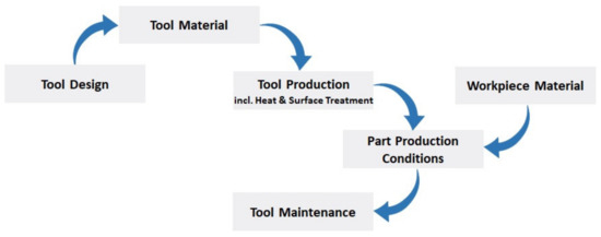
Figure 3.
Factors that influence the tool life.
The failure mechanism encountered in cold working tools, e.g., stamping tools and dies, comprise abrasive and adhesive wear or mixed wear (caused by sliding contact), chipping at cutting edges and corners (fatigue), plastic deformation (exceeding the yield strength locally), cracking (fatigue), and galling (the same mechanism as in adhesive wear). The tool concept (tool material, hardness, surface roughness and treatment) is highly related to the workpiece material (sheet material grade, surface and thickness). The tool concept for 1-mm thick hot-dip galvanized DP600 steel sheet differs therefore from that for 1-mm thick uncoated DP1000 steel sheet [40,41,42].
For hot-working tools, i.e., tools and dies in high pressure die casting, hot forging, hot stamping, or extrusion, thermal fatigue (heat checking), corrosion/erosion, cracking (total failure), and indentation are some of the failures that need to be avoided. Thermal fatigue is dependent upon thermal expansion coefficient (should be low), thermal conductivity (should be high), hot yield strength (should be high), temper resistance (a good resistance to softening at high temperature exposure), creep strength (should be high), and ductility. In other words, the tool should display resistance to deformation, softening, wear, impact loading and corrosion/erosion at the working temperature, [43,44,45].
Some injection molds are likely to be exposed to corrosion, since the plastic materials can produce corrosive by-products, e.g., PVC, and/or due to condensation caused by prolonged production stoppages, humid operating or storage conditions. In such cases, a stainless tool steel is required. Through-hardened molds are used, if the production runs are long, abrasion from certain molding materials needs to be avoided, and/or the closure or injection pressures are high. However, large molds and molds with low demands on wear resistance can be made in pre-hardened steel. Good polishability and excellent surface finish are key requirements for many injection molds [46,47].
Tool steels are classified according to composition, hardness, properties, or application. According to the classification system developed by the American Iron and Steel Institute (AISI), tool steels can be subdivided in seven different groups, based on prominent characteristics such as alloying elements, heat treatment and application. These groups are displayed in Table 3. The properties of some of these conventionally common tool steels are displayed in Table 4.
Table 3.
AISI classification of (conventional) tool steels [48,49].
Table 5 shows the most common powder steels used to make tools by L-PBF. The number of these tool steels for L-PBF is, as displayed in this table, still very limited. M789 AMPO, L-40, W360 AMPO and AM Corrax were launched within the past 2–3 years, while the maraging steel grade 300, the stainless steels 316L and 17-4PH, and the tool steel H13 have been studied more thoroughly in tooling applications much longer.
Table 4.
Some of the properties of some common conventional tool steels. All values labelled with ① are from [50]. All other values are extracted from [48].
Table 4.
Some of the properties of some common conventional tool steels. All values labelled with ① are from [50]. All other values are extracted from [48].
| AISI Classification | AISI (USA) | W.-Nr. (Germany) | Yield Strength (MPa) | Ultimate Tensile Strength (MPa) | Usual Working Hardness (HRC) | Thermal Conductivity (W/(mK)) ① | Machinability | Wear Resistance | Tougness | Hot Hardness |
|---|---|---|---|---|---|---|---|---|---|---|
| High speed steels | M3:2 | 1.3344 | - | 2210 ① (hardened to 68 HRC) | 63–66 | 26 | 4 | 8 | 3 | 8 |
| T15 | 1.3202 | - | 2240 ① (hardened to 69 HRC) | 64–68 | 21 | 1 | 9 | 1 | 9 | |
| Cold-work steels | A2 | 1.2363 | - | 1858 ② | 57–62 | 38 | 8 | 6 | 4 | 5 |
| D2 | 1.2379 | 1510 ① (hardened to 62 HRC) | 2000 ① (hardened to 62 HRC) | 58–64 | 31 | 3 | 8 | 2 | 6 | |
| O1 | 1.2510 | 1538 ③ | 1710 ③ | 57–62 | 43 | 8 | 4 | 3 | 3 | |
| W1 | 1.1545 | - | 2320 ① (hardened) | 72 ① | 48 | |||||
| Hot-work steels | H11 | 1.2343 | 1482 | 1806 | 38–55 | 42 | 8 | 3 | 9 | 6 |
| H13 | 1.2344 | - | 1820 ① (hardened to 56 HRC) | 40–53 | 29 | 8 | 3 | 9 | 6 | |
| H21 | 1.2581 | 1193 | 1379 | 50–55 | 27 | 6 | 4 | 8 | 8 | |
| H41 | - | - | 2210 ① (hardened) | 68 ① | 28 | |||||
| Shock-resisting steels | S1 | 1.2550 | - | 1840 ① (hardened to 57 HRC) | 50–58 | 41 | 8 | 4 | 8 | 5 |
| Mold steels | P20 | 1.2311 | 1172 ④ | 1310 ④ | 30–50 | 45 | 8 | 1a | 8 | 2a |
| Special purpose steels | L2 | 1.2210 | 1546 ⑤ with V | 1605 ⑤ with V | 45–60 | 44 | 8 | 1 | 7 | 2 |
① The values are from [50]. (All other values are extracted from [48].). ② Hardened from 945 °C/Tempered at 540 °C. ③ Oil quenched/tempered at 425 °C. ④ After oil quenching from 845 °C and tempering 2 h at 205 °C. ⑤ Oil quenched from 840 °C/tempered at 425 °C.
Table 5.
L-PBF: the major tool powder steels so far and the associated tooling applications.
Table 5.
L-PBF: the major tool powder steels so far and the associated tooling applications.
| Class | Name/AISI Designation | DIN Designation | Tooling Applications |
|---|---|---|---|
| Maraging steel | 18Ni-Grade 300 (See also Böhler M722 AMPO) | 1.2709 | Cold and hot forming, injection molding etc. |
| Böhler M789 AMPO | - | Injection molding, plastic extrusion, tool holders etc. | |
| Formetrix L-40 | - | Injection molding etc. | |
| Stainless steel | 316L | 1.4404 | Injection molding etc. |
| 17-4PH | 1.4542 | Extrusion (metal powder and additives (polymers and waxes)), Injection molding etc. | |
| 420 | 1.4021 | Injection molding etc. | |
| Tool steel | M2 | 1.3343 | Cutting etc. |
| H13 | 1.2344 | Hot forging, die casting, extrusion and injection molding | |
| Böhler W360 AMPO | - | Extrusion, hot forging, hot stamping, injection molding, high-pressure die casting | |
| Uddeholm AM Corrax | - | Extrusion of plastic, injection molding |
The chemical compositions of these powder steels are shown in Table 6. The properties of the tools made by L-PBF in these powder steels are displayed in Table 7. These tables are based on [33,51,52,53,54,55,56,57,58,59,60,61,62].
Maraging steel has been used widely in additive manufacturing for applications, where high strength, toughness and ductility at high hardness and dimensional stability are required. Maraging steel’s low-carbon soft martensitic matrix is mostly free from interstitial alloying elements, which rank it as an excellent candidate for synthesis by AM and welding [63].
316L is used in a large variety of applications where the tool is in contact with corrosive media at moderate temperatures during service. In, for instance, injection molding, where an overlap of corrosion resistance and increased mechanical strength and hardness (compared to austenitic stainless steels) is required, the so-called PH steel grades such as 17-4PH (i.e., the maraging-type precipitation-hardened martensitic stainless steels) are used [51]. See also Table 5, Table 6 and Table 7.
420 is the only martensitic stainless steel grade in use so far. The phase content of the microstructure depends strongly on the chosen process parameters. In L-PBF (where the laser power is high), the process can result in retained austenite as well. This will in turn yield a hardness that is comparable with the wrought material [57]. See Table 6 and Table 7.
As displayed in Table 6, low carbon maraging steels and carbon-bearing tool steels (e.g., M2 and H13) are used in toolmaking by L-PBF. Martensite with precipitates is the microstructure in both. In the case of carbon-bearing tool steels, the martensitic matrix without precipitates obtained upon quenching is hard and brittle and tempering serves to regain some ductility by precipitating carbon from the martensite matrix in the form of carbides. In the case of the high-Ni maraging steels, quenching leads to a comparably soft and ductile martensitic microstructure which gains its strength by precipitation of intermetallic-phase particles upon ageing [51,63]. See also Table 7.
Since the cooling rates in L-PBF are high, martensite is formed in both maraging and tool steels during AM. Therefore, maraging steels with a ductile martensitic microstructure are well processable in AM while carbon-bearing tool steels (M2 and H13) with a brittle martensitic microstructure tend to crack due to the thermal stresses during the AM. A considerable fraction of the literature on carbon-bearing tool steels regard the optimum process parameters to make crack free, dense samples. In contrast, for maraging steels most studies are aimed at optimizing microstructures, mechanical properties and post process heat treatments [51,63]. See also Table 6 and Table 7.
The conducted investigations show that crake free and fully dense tools can be made by L-PBF in the materials displayed in Table 5, Table 6 and Table 7 [51,54,55,56,57,58,59,60,63]. See also [62].
Table 6.
The chemical composition of the major tool powder steels for additive manufacturing.
Table 6.
The chemical composition of the major tool powder steels for additive manufacturing.
| Class | Name/Designation | Alloying Elements (wt.%), (Fe = Balance) | ||||||||||||||||
|---|---|---|---|---|---|---|---|---|---|---|---|---|---|---|---|---|---|---|
| C | Mn | P | Si | Cr | Mo | Co | Ni | V | Al | Ti | Nb | Cu | N | S | W | Ref. | ||
| Maraging steel | 18Ni-Grade 300 (M722 AMPO, DIN 1.2709) | ≤0.03 | ≤0.15 | ≤0.01 | ≤0.10 | - | 4.5–5.20 | 8.5–10.0 | 17.0–19.0 | - | - | 0.8–1.2 | - | - | - | ≤0.01 | - | [33], see also [51] |
| M789 AMPO | <0.02 | - | - | - | 12.2 | 1.0 | - | 10.0 | - | 0.6 | 1.0 | - | - | - | - | - | [52]] | |
| Formetrix L-40 | <0.1 | - | - | - | >10.5 | <5.0 | - | <5.0 | - | - | - | <1.0 | <1.0 | <1.0 | - | - | [53] | |
| Stainless steel | AISI 316L (DIN 1.4404) | ≤0.03 | ≤2.0 | ≤0.045 | ≤1.0 | 16.5–18.5 | 2.0–2.5 | - | 10.0–13.0 | - | - | - | - | - | ≤0.11 | ≤0.03 | - | [33], see also [54] |
| 17-4PH (DIN 1.4542) | <0.07 | <1.0 | < 0.04 | <1.0 | 15.0–17.5 | - | - | 3.0–5.0 | - | - | - | +Ta 0.15–0.45 | 3.0–5.0 | - | <0.03 | - | [33], see also [51] | |
| AISI 420 (DIN 1.4021) | 0.3 | 0.72 | 0.012 | 0.79 | 12.8 | 0.5 | - | 1.0 | - | - | - | - | - | 0.09 | 0.008 | - | [56] | |
| Tool steel | AISI M2 (DIN 1.3343) | 0.9 | 0.38 | - | 0.35 | 3.97 | 4.89 | - | 0.3 | 1.82 | - | - | - | 0.25 | - | 0.03 | 6.15 | [58] |
| H13 (DIN 1.2344) | 0.32–0.45 | 0.2–0.6 | - | 0.8–1.2 | 4.75–5.5 | 1.1–1.75 | - | - | 0.8–1.2 | - | - | - | - | - | - | - | [51], see also [59] | |
| W360 AMPO | 0.5 | 0.25 | - | 0.2 | 4.5 | 3.0 | - | - | 0.55 | - | - | - | - | - | - | - | [52] | |
| P20 * (DIN 1.2311) | 0.4 | 0.83 | - | 0.45 | 1.95 | 0.33 | - | - | - | - | - | - | 0.02 | - | - | - | [60] | |
| AM Corrax | 0.03 | 0.3 | - | 0.3 | 12.0 | 1.4 | - | 9.2 | - | 1.6 | - | - | - | - | - | - | [61] | |
* P20 is a common conventional material for conventionally designed and manufactured injection moulds. Its chemical composition is given here only for comparison.
Table 7.
The properties of the tools made by additive manufacturing through L-PBF in the powder steels shown in Table 6.
Table 7.
The properties of the tools made by additive manufacturing through L-PBF in the powder steels shown in Table 6.
| Class | Name/Designation | Building Direction | Yield Strength (MPa) | Ultimate Tensile Strength (MPa) | Elongation at Break (%) | Hardness (HRC) | Impact Toughness (J) | Thermal Conductivity (W/(m.K) | Ref. | |||||
|---|---|---|---|---|---|---|---|---|---|---|---|---|---|---|
| As-Built | After Heat Treatment1 | As-Built | After Heat Treatment 1 | As-Built | After Heat Treatment 1 | As-Built | After Heat Treatment 1 | As-Built | After Heat Treatment 1 | |||||
| Maraging steel | 18Ni-300 (DIN 1.2709) | Horizontal | 1080 ± 90 | 2180 ± 40 | 1230 ± 70 | 2260 ± 30 | 13 ± 2 | 5 ± 2 | 35 ± 3 | 55 ± 3 | 64 ± 5 | 7 ± 2 | 20.9 at 25 °C | [33], see also [51] |
| Vertical | 1090 ± 50 | 2070 ± 80 | 1220 ± 20 | 2160 ± 90 | 13 ± 2 | 2 ± 1 | ||||||||
| M789 AMPO | - | - | 1720 ± 50 | - | 1850 ± 50 | - | 6 ± 2 | - | 52 ± 1 | - | 6–14 | - | [52] | |
| Formetrix L-40 | - | 1300 | 1350 | 1500 | 1650 | 14 | 10 | 46–48 | 50–52 | 60 | 18 | 16.3 at 20 °C | [53] | |
| Stainless steel | AISI 316L (DIN 1.4404) | Horizontal | 530 ± 20 2 | 370 ± 30 3 | 660 ± 20 2 | 610 ± 30 3 | 39 ± 5 2 | 51 ± 5 3 | 90 ± 6 HRB | 83 ± 4 HRB | 215 ± 15 | 220 ± 15 | 15 at 20 °C | [33], see also [54] |
| Vertical | 440 ± 20 2 | 320 ± 20 3 | 570 ± 30 2 | 540 ± 30 3 | 49 ± 5 2 | 66 ± 5 3 | ||||||||
| 17-4PH (DIN 1.4542) | Horizontal | - | 1280 ± 30 4 | - | 1450 ± 10 4 | - | 11 ± 1 4 | 32 ± 4 | 40 ± 2 4 | 71 ± 20 | 7 ± 2 4 | 18 at 100 °C | [33], see also [55] | |
| Vertical | 830 ± 110 | 1260 ± 100 4 | 1100 ± 90 | 1380 ± 20 4 | 19 ± 4 | 12 ± 2 4 | ||||||||
| AISI 420 (DIN 1.4021) | - | 700 ± 15 | 950 ± 20 | 1050 ± 25 | 1520 ± 30 | 2.5 ± 0.2 | 6.3 ± 0.2 | 55 ± 1 | 53 ± 1 | - | - | - | [56], see also [57] | |
| Tool steel | AISI M2 (DIN 1.3343) | - | - | - | 1280 | - | 0.8 | - | 57 | 64 5 | - | - | - | [58] |
| H13 (DIN 1.2344) | - | 1003 ± 8.5 | 1580 ± 14.7 2 | 1370 ± 175.1 | 1860 ± 55.8 2 | 1.7 ± 0.6 | 2.2 ± 0.8 2 | 59 ± 4.6 | 51 ± 3.7 2 | - | - | 27 at 500 °C | [59], see also [51] | |
| W360 AMPO | - | - | 1500–1670 | - | 1970–2010 | - | 6.6–8.1 | - | 55–57 | - | 8–14 | - | [52] | |
| AM Corrax | - | 760 | 1600 | 1150 | 1700 | 16 | 10 | 34 | 50 | - | 18.7 | - | [61], see also [62] | |
1 Ageing. 2 After stress relief. 3 Full anneal. 4 H900. 5 Every layer is remelted during L-PBF.
5. L-PBF Process Parameters
The quality of the feedstock (metal powder) and the process parameters used in L-PBF are of key significance for the process performance and determine the microstructure and thereby the quality of the end part (in this case, the tool) [64,65,66,67,68,69,70,71,72,73,74,75,76,77,78,79,80,81,82,83,84,85,86,87,88,89,90,91,92].
Table 8 displays the L-PBF processing parameters that result in fully dense objects (tool in this case) in the shown materials. Compare Table 8 with Table 5, Table 6 and Table 7.
Table 9 summarizes the proposed measures to combat build and microstructural problems in L-PBF.
Table 9.
Measures to combat build and microstructural problems in L-PBF. Based on [74].
The difference between maraging steel, DIN 1.2709, and tool steel, H11 and H13, can be used to illustrate how the measures to combat build and microstructural problems vary from material to material. Since the cooling rates in L-PBF are high, 105–106 K·s−1, martensite formation is induced in both steel types. The so-called carbon-free DIN 1.2709 obtains a ductile martensitic microstructure (and is well processable in L-PBF), while the carbon-bearing H11 and H13 display a brittle martensitic microstructure that tends to crack due to the thermal stresses built up by the high cooling rates [51,85]. The conducted studies show that a pre-heating of the base plate (building platform) eliminate the cracking [30,51].
Martensitic microstructure is found in crack-free H13 for all pre-heating temperatures up to 300 °C. Cracking is, in other words, avoided due to lower thermal gradients and reduced residual stresses. A base plate heated to 400 °C results in a change in the phase transformation and a bainitic microstructure (the part is kept above the martensite start temperature) is formed instead. The bainitic microstructure displays higher hardness and tensile strength than the martensitic microstructure formed at lower heating temperatures [51].
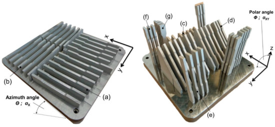
The roughness of the functional tool surfaces is of great significance in all tooling applications. Figure 4 displays (a) the different surface types on a part fabricated by and (b) the staircase effect in L-PBF.
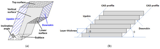
Figure 4.
(a) schematic presentation of the different surface types on a part fabricated by L-PBF [93]. (b) Schematic presentation of the staircase effect.
The staircase effect increases with layer thickness and decreasing θ angle. The conducted studies show that the downskin exhibits the highest roughness in L-PBF, since the material is built upon powder (and not on solid material). The downskin surface exhibits a roughness of 20–65 μm in these investigations [94,95]. For the top surface, a roughness of 5 μm can be achieved in L-PBF [62].
L-PBF is not yet capable to accomplish the surface roughness required in the tooling applications [96,97,98,99,100,101]. The tool made by L-PBF needs to be machined during post-processing to obtain the required surface roughness. The functional tool surfaces must therefore have an allowance of 0.2–0.5 mm [65].
Benchmarking artifacts have been proposed, designed, fabricated by L-PBF and evaluated during the past years to assess the capabilities and limitations of the process and the performance of different machines. The evaluation of the geometrical performance of L-PBF and the dimensional accuracy of objects made by L-PBF has been one of the purposes for such artifacts [102,103,104,105]. Figure 5 displays such artifacts.
Seven (7) state-of-the-art L-PBF machines were used to produce the artifact in Figure 5 in maraging steel 18Ni-300 (DIN 1.2709). Each machine made three complete jobs (artifacts). Table 10 shows the minimum dimensions in the artifact in Figure 5 compared with the minimum dimensions the most capable machine manufacturers claimed to be able to produce. This benchmarking study overcame most of the limitations stated by the machine manufacturers in Table 10. It showed that user experience and expertise were of great significance. The newest machines did not outperform the oldest machine due to this user’s experience and expertise. To create an own space in industrial production, L-PBF needs to become more robust, i.e., less dependent upon the user experience and better repeatability [105].
This observation in [105], i.e., the large role played by the user experience and expertise, was made also in [106]. Rings 1-mm thick and 30-mm high were made by L-PBF in the diameters 25, 50 and 85 mm in tool steel H13 (DIN 1.2344). The dimensional accuracy was then measured and analyzed. These rings were made using two different L-PBF scanning strategies—a stripe scan strategy that is automatically generated and provided by the machine manufacturer and a (manually designed) sectional scan strategy, Figure 6. The dimensional accuracy of ring specimens could be improved by up to 81% with the introduced sectional strategy compared to the standard approach [106].

Figure 5.
The Artifact with spiral on benchmarking in [105]. The figure is from [104].
Figure 5.
The Artifact with spiral on benchmarking in [105]. The figure is from [104].

Table 10.
The minimum dimensions in the artifact in Figure 5 compared with the minimum dimension the most capable machine manufacturers claimed to be able to produce. Material = 18Ni-300 (DIN 1.2709). Seven (7) state-of-the-art L-PBF machines were used to produce 3 complete jobs (artifacts) each [105].
| Feature | Minimum Dimension | Min Dimension in Artifact |
|---|---|---|
| Wall thickness | 0.15 mm | 0.10 mm |
| Overhang structure | 45° | 25° |
| Circular holes (diameter) | 0.50 mm | 0.20 mm |
| Circular pins (diameter) | 0.50 mm | 0.10 mm |

Figure 6.
(a) The stripe scan strategy automatically generated and provided by the machine manufacturer and (b) the manually designed sectional scan strategy [106].
Figure 6.
(a) The stripe scan strategy automatically generated and provided by the machine manufacturer and (b) the manually designed sectional scan strategy [106].

6. Tool Design for Metal Additive Manufacturing by L-PBF
Additive manufacturing provides a significantly larger design freedom (compared to conventional manufacturing), the benefits of which can be maximized by the emerging computer-aided design (CAD) technologies like generative design (GD). It is now possible to:
- (1)
- Generate a wide range of design alternatives by artificial intelligence-based algorithms (GD software) after setting the part/object design space, constraints, criteria and objectives. The designer reviews the different design options and chooses the best-suited for the application [107,108].
- (2)
- Topology optimize the selected design alternative, the purpose of which is to remove unnecessary material while meeting (or exceeding) the performance criteria. The goal is to optimize a part properly (weight, stiffness, frequency …) while respecting a certain set of constraints. The topology optimization process uses various mathematical algorithms and methods (each having several versions) [109,110,111,112].
- (3)
- Optimize the internal lattice and surface structure of the topology optimized object by creating an internal mesh while meeting (or exceeding) the performance criteria [113,114,115,116].
- (4)
- Produce this complex object by L-PBF (and post-processing).
During the past two decades, different new design methodologies have emerged, among them the Design for X (DfX). X represents a particular perspective to improve during the product design as well as the design process [117,118]. DfX applied to the Additive Manufacturing process is named DfAM. It aims at using the full potential of the AM technologies for design, for which there are two methods [108,119,120].
A new detailed DfAM process has been proposed including the available design support (methods, design rules, guidelines and software tools), the tools and methods that are best suited at different stages of the design process are specified, and the possibility to achieve a more automated DfAM is indicated [121].
As far as the L-PBF process design (i.e., the preparation of the L-PBF process) is concerned, the part orientation, support structures, overhangs and part supporting angles, channels and holes, wall thickness, tolerances and offsets are addressed in [122,123,124]. VDI 3405 Part 2, [122], addresses the qualification, quality assurance and post processing. The procedure described in this standard is applied to DIN 1.2709 in a VDI inter-laboratory test. The obtained properties in this inter-laboratory test are accounted for in [122]. The values for DIN 1.2709 in Table 6 and Table 7 are in parity with the values stated for the same material in [122].
The angle between the building platform and the building direction is also of great significance for the properties of the as-built object. In other words, the properties of the as-built object are anisotropic due to the layered manufacturing, the loading direction etc. Table 11 and Figure 7 display 7 different configurations, in which tensile specimens in 316L (1.4404) were built with an oversize of 0.4 mm in width and thickness. After milling to final shape, the specimens were tested. Table 12 displays the tensile properties of these specimens. The maximum strength is obtained at a 45° layer versus loading offset [125].
Design demands knowledge of the precise material properties. These properties are anisotropic and the component orientation on the build platform needs therefore to be considered [125]. (Post L-PBF heat treatment affects also these properties. See the properties of 316L (1.4404) before and after heat treatment in Table 7.)
It is possible to achieve ±0.2% in tolerance, with the minimal value being 0.2 mm. It is also possible to achieve a wall thickness of 0.5 mm. However, the wall shape is dependent upon the orientation, its height (in relation to the thickness), and the possibility to have support if needed. As far as gaps (between walls or solid portions) are concerned, the minimum gap width should be larger than at least the melt pool width. It is also important to add an allowance of 0.3–0.5 mm to the locations and surfaces that require post-processing by machining to reach the required tolerance and surface roughness [114,122].
7. Examples of Tooling Applications Designed for and Made by L-PBF
Research and development have been conducted on toolmaking for cold working, hot working and injection molding by an L-PBF inclusive process, i.e., design for L-PBF (metal AM), L-PBF, and post-processing. In the following, some examples of the studied tooling applications are accounted for. These examples display the scientific and technological achievements and the commercial benefits of an L-PBF inclusive toolmaking.
7.1. Cold Working
7.1.1. Piercing Punches
100-mm long cylindrical punches with a piercing diameter of φ10 mm were made by L-PBF in H13, M300, and KP4. These punches were made vertically with a layer thickness of 50 μm. Durability studies were conducted by using these punches to make round holes in 1.2-mm thick CP1180 sheet steel with a tensile strength of 1200 MPa. Conventionally manufactured punches in conventional solid SKD11 and HWS were used in this investigation for comparison. The M300 punch had the best mechanical properties among the additively manufactured punches and exhibited the same performance, i.e., managed 10,000 strokes, as the conventional SKD11 and HWS punches. Process optimization and the application of other powder metals are indicated as topics for further investigations [126].
7.1.2. Stamping: Case 1
In a comparison of different additive manufacturing methods, a small prototyping sheet metal forming tool (bending matrix, holding block and die) was made in ABS, VeroGrey, PEAK, and H13. The variant made by L-PBF in H13 (vertically built with a layer thickness of 30 μm) exhibited the smallest form deviations, took the longest time to print, and had the highest production costs [127].
7.1.3. Stamping: Case 2
To study the potential of additive manufacturing in automotive stamping, 3 cutting inserts (the largest being 200 × 135 × 65 mm3), a calibration insert (205 × 97 × 56 mm3) and a blankholder insert (95 × 44 × 44 mm3) were made by an L-PBF inclusive process in DIN 1.2709. These inserts were printed as solid objects and hade a hardness of 38 HRC after L-PBF. After heat treatment in a vacuum at 490 °C in 6 h, the inserts were machined to a surface roughness of 0.2 μm. The final hardness was 57 HRC and the inserts managed one million strokes/hits per insert. The costs were more than doubled and the lead time was more than halved, compared to conventional toolmaking [128].
7.1.4. Stamping: Case 3
To study the potential of topology optimization of the stamping tools, certify such tools, and study the options in design and manufacturing of such tools, semi-industrial forming (u-bending) and trimming tools were made by an L-PBF inclusive process [129,130,131,132].
The left U-bending tool half in Figure 8 was topology optimized and 3D-printed (L-PBF). The right U-bending tool half in the same figure was 3D-printed solidly. Both tool halves were 3D-printed in DIN 1.2709. LS-TaSC (LS-Dyna) was used for the topology optimization and the Z-displacement at the tool half profile radius was the compliance criterion. The volume fraction of 0.45 was selected, since the maximum Z-displacement at this fraction is very close to that of the solid [129,130,131]. See Figure 8, Figure 9 and Figure 10.
After L-PBF, the U-bending tool halves were heat treated at 490° C in 6 h and then machined to a surface roughness of 0.2 μm. The hardness was 55 HRC. This tool was used to U-bend 2-mm thick hot-dip galvanized DP600 steel sheet with a minimum tensile strength of 600 MPa. This tool managed 50,000 strokes (U-bends) without any problems and was approved [129]. See Figure 8.
Compared to the 3D-printed solid tool half, the topology optimized and 3D-printed tool half exhibited a weight reduction (or improved material usage) by 19.4% and a lead time reduction by 11.1%. Initially, the profile radius of the left tool half (topology optimized) was 5.05 mm and that of the right tool half (solid) was 5.04 mm. After 50,000 strokes, the maximum wear measured as a change in the profile radius was 0.0186 mm [129]. See Figure 8.
Figure 11 displays the 3D-printed (L-PBF) semi-industrial solid and topology optimized trimming tools. The hardness varies between 54 and 56 HRC. The surface roughness Ra = 0.2 μm. Both the solid and topology optimized tools managed 100,000 strokes in 2-mm thick DP600 sheet steel without any problems and were approved. Figure 12 shows the wear after 100,000 strokes at the edge (profile) radius on the trim dies. Compared to the 3D-printed solid tool, the topology optimized and 3D-printed tool exhibits a weight reduction by 47% and a lead time reduction by 29.6%, Figure 11, [131,132].
Based on the approved semi-industrial results above, a station in an industrial progressive die used to stamp 1-mm thick DP600 sheet steel was chosen and 3D-printed (L-PBF) in DIN 1.2709 with a honeycomb inner structure. This station comprises a punch and a puller, as shown in Figure 13 [62] (see also [129]).
The punch in this industrial stamping tool, Figure 13, was topology optimized using LS-TaSC with a volume fraction of 0.45 as the target, and using NX12 with a weight reduction by 70% as the target. The shape and the resultant displacements prior to unloading (in stamping) in the punch with the original design and the topology optimized versions are displayed in Figure 14 [62,131]. These topology optimized versions, both 3D-printed in DIN 1.2709, are shown in Figure 15.

Figure 8.
The U-bending tool: the right tool half was 3D-printed (L-PBF) as a solid piece. The left tool half was topology optimized at the volume fraction of 0.45 (Figure 9) and 3D-printed (L-PBF). Both tool halves were 3D-printed in maraging steel DIN 1.2709. Both tool halves managed 50,000 U-bends and were approved [129]. All displayed dimensions are in mm.


Figure 9.
Topology optimization of the U-bend tool (Figure 11) with different volume fractions [130].
Figure 9.
Topology optimization of the U-bend tool (Figure 11) with different volume fractions [130].


Figure 10.
The Z-displacement at the U-bending tool profile radius for different volume fractions (Figure 9) [131].
Figure 10.
The Z-displacement at the U-bending tool profile radius for different volume fractions (Figure 9) [131].


Figure 11.
The 3D-printed (L-PBF) solid and topology optimized trimming tools. Both versions were 3D-printed (L-PBF) in DIN 1.2709 [131]. All displayed dimensions are in mm.
Figure 11.
The 3D-printed (L-PBF) solid and topology optimized trimming tools. Both versions were 3D-printed (L-PBF) in DIN 1.2709 [131]. All displayed dimensions are in mm.


Figure 12.
The wear after 100,000 strokes at the edge (profile) radius on the trim dies [132].
Figure 12.
The wear after 100,000 strokes at the edge (profile) radius on the trim dies [132].


Figure 13.
A station in an industrial progressive die, used to stamp 1-mm thick DP600 sheet steel, 3D-printed (L-PBF) in DIN 1.2709 with a honeycomb inner structure [62] (see also [129]). The displayed dimension is in mm.
Figure 13.
A station in an industrial progressive die, used to stamp 1-mm thick DP600 sheet steel, 3D-printed (L-PBF) in DIN 1.2709 with a honeycomb inner structure [62] (see also [129]). The displayed dimension is in mm.


Figure 14.
The shape and the resultant displacements prior to unloading in the punch (a) with the original design and (b) topology optimized with the volume fraction 0.45 using LS-TaSC, and (c) topology optimized using NX12 and targeting a weight reduction by 70% (compared to the conventionally designed solid version) [62,131]. All displayed dimensions are in mm.


Compared to a 3D-printed solid punch, both the honeycomb inner structure and the topology optimization with the volume fraction of 0.45 improved the material usage (and thereby reduced the weight) and the printing time by ca 45% & ca 34% respectively. This means that the same printing time reduction and improved material efficiency can be accomplished in at least two different fashions—topology optimization and a honeycomb inner structure [62]. See Figure 15.
The topology optimization targeting a weight reduction by 70% (compared to the solid version made conventionally) led to much larger displacements held to have a large negative impact on the trimming result and the die life length [62]. See Figure 15.
7.2. Hot Working
7.2.1. Hot Stamping
Hot stamping, or press hardening, is a process used to form lightweight high strength (2000 MPa) structural car body parts. The thin steel sheet is heated to the austenitizing temperature (ca 950 °C), formed, and rapidly cooled down to 200 °C in the forming tool. This leads to martensitic high strength structure. The cooling, the time the die must be kept closed after forming and before unloading (the holding time), dominates the cycle time. To accomplish the cooling, channels are drilled (ca one hour per meter borehole) [114].
To accomplish improved cooling and maximize the benefits, a so-called hybrid tooling approach was selected. The tool base was made by conventional milling of a conventionally made solid block. The functional structure was made by L-PBF in DIN 1.2709 over this tool base, as shown in Figure 16 and Figure 17. Before L-PBF, this functional structure was optimized through thermo-fluidic simulations and by placing the cooling channels very close and conformal to the surface. Due to the optimized cooling, the part was cooled down more rapidly and evenly. The holding time could be reduced from initially 10 to 5 s [133]. See Figure 18.
7.2.2. Extrusion: Case 1
During extrusion, the feedstock is heated up and pushed through a forming tool. The formed shape needs to be cooled down and maintained. To do so, a calibration tool is used directly after the extrusion. The cooling is accomplished by a fluid flowing through the cooling channels. The vacuum, accomplished through the vacuum channel, forces the extruded material to adopt the cylindrical inner surface of the calibration tool. Thereby, the extruded geometry is fixed and “calibrated” [114].
The tool described above was specially designed for AM by integrating the complex internal channels in a limited design space. After design, the calibration tool was made by L-PBF in 17-4PH. For the internal channels, tolerances in the range of ± 0.5 mm were met. The channel diameter had to be about 3 mm to be able to get rid of the not bound powder [114]. See Figure 19 and Figure 20.
There is no conventionally manufactured predecessor. Comparable conventionally manufactured tools use compressed air for calibration. Better thermal and calibration performance and the reduced size are the main benefits of the calibration tool in Figure 19 and Figure 20 compared to the conventional less effective tools [114].

Figure 16.
Tool insert for hot stamping made by the so-called hybrid tooling. The tool base was made by conventional milling of a conventionally made solid block (left). The functional structure including the optimized cooling channel was made by L-PBF in DIN 1.2709 over this tool base (right). The figure (right) shows the hybrid tool ready for final machining [133].


Figure 17.
The assembled hot stamping punch [114].
Figure 17.
The assembled hot stamping punch [114].


Figure 18.
The temperature distribution in the hot stamping punch: (left) the conventional tool and (right) the tool designed for and made by L-PBF [133].
Figure 18.
The temperature distribution in the hot stamping punch: (left) the conventional tool and (right) the tool designed for and made by L-PBF [133].


Figure 19.
The calibration tool: The internal cooling and vacuum channels were integrated in a very compact design space. The minimum distance between the channels is about 1 mm [114].
Figure 19.
The calibration tool: The internal cooling and vacuum channels were integrated in a very compact design space. The minimum distance between the channels is about 1 mm [114].


Figure 20.
The calibration tool was made by L-PBF in 17-4PH [114].
Figure 20.
The calibration tool was made by L-PBF in 17-4PH [114].

7.2.3. Extrusion: Case 2
In another study, the thermal control and the maintenance of a uniform temperature in the extrusion process of aluminum alloys was at the focus. The purpose was to generate sound profiles with high press productivities. Numerical studies were conducted to check the mechanical and thermal performances of die inserts both in uncooled and cooled conditions. Conformal cooling channels through which liquid nitrogen flowed was the targeted cooling system. A thermally controlled die insert was designed and made in H13 by L-PBF. Initially, cracks due to thermally induced stresses caused problems. This problem was solved by reducing the waiting time for one layer to another layer melting. The crack-free insert made by L-PBF is shown in Figure 21. This insert was then integrated into a conventionally machined steel housing [134]. The height and outer diameter of the insert in Figure 21 are 20 mm and 25 mm respectively [135].
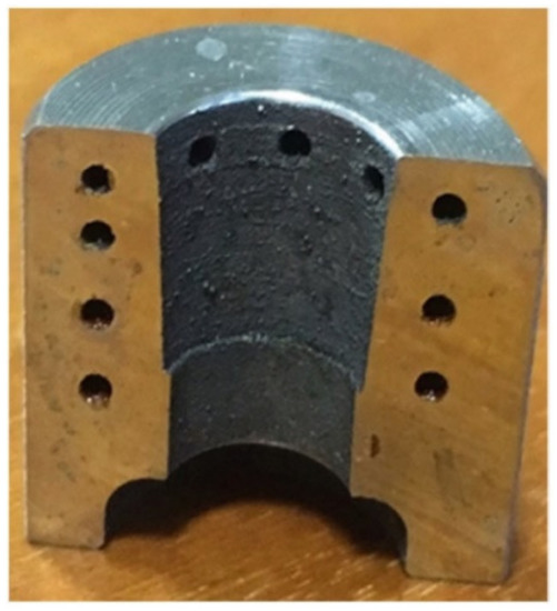
Figure 21.
An extrusion die insert with conformal cooling channels through which liquid nitrogen flow. This die insert was made by L-PBF in H13 and integrated into a conventionally machined steel housing [134]. The height = 20 mm and the outer diameter = 25 mm [135].
7.2.4. Die Casting: Case 1
The bedplate for a passenger car engine was to be manufactured regularly by aluminium die casting in the alloy EN AC-Al Si9Cu3 (Fe). Gas and shrink porosity were some of the chief problems encountered in the initial testing phases. The conducted investigations resulted in an insert made by L-PBF in DIN 1.2709 mounted as a component in the die [133], as shown in Figure 22.
The optimization of the cooling channels in this insert comprised [133]:
- FE-simulations to obtain the shortest possible distance between the cooling and the cavity on one hand and sufficient insert strength on the other.
- Thermal simulations to optimize the cooling channels in steps, ranging from spiral design to a complex system of small channels, as shown in Figure 23.
The optimized insert reduced the gas and shrinkage porosity to a permissible level, the scrap rate by 10% and the cycle time by 3% [133].

Figure 22.
Aluminium die casting: (left) The tool insert was made in DIN 1.2709 by L-PBF, after which it was installed as a component in the die [133].
Figure 22.
Aluminium die casting: (left) The tool insert was made in DIN 1.2709 by L-PBF, after which it was installed as a component in the die [133].


Figure 23.
The insert in Figure 22: Stepwise optimization of the cooling channels, ranging from spiral design to a complex system of small channels [133].
Figure 23.
The insert in Figure 22: Stepwise optimization of the cooling channels, ranging from spiral design to a complex system of small channels [133].

7.2.5. Die Casting: Case 2
In another study, the main objective was to investigate the benefits of conformal cooling in the tool used to manufacture sample batches of zinc alloy castings. A hybrid approach was chosen to reduce the process and material costs. The impression block in Figure 24 was made of two pieces separated at the dashed line [136]:
- The upper piece, which includes the cores and the conformal cooling channels, was built by L-PBF from powders of AISI H11 (DIN 1.2343). An allowance of 0.3 mm was left for CNC finish milling after a thermal treatment.
- The lower piece, which is 25 mm thick and includes the inlet and outlet ports for the coolant, was built by CNC machining from a blank made of the same steel.
The main lines of the cooling system were placed on the parting plane to ease powder removal. The whole process took 180 h, of which 91 h for the additive manufacturing phase [136].
Figure 25 displays the redesigned impression block with the conformal cooling channels. The conformal cooling improved the surface finish of the castings (due to a reduced need of spray cooling) and reduced the time and shrinkage porosity [136].

Figure 24.
The impression block, a die for zinc alloy castings, was made by applying a hybrid approach. The upper piece was made by selective laser melting (SLM) or L-PBF from powders of AISI H11 (DIN 1.2343). The lower piece was built by CNC machining from a blank made of the same steel [136]. See also Figure 25. All displayed dimensions are in mm.


Figure 25.
Redesigned impression block, a die for zinc alloy castings, with conformal cooling channels [136]. (a) The impression block. (b) The conformal cooling channels inside the impression block. See also Figure 24.
Figure 25.
Redesigned impression block, a die for zinc alloy castings, with conformal cooling channels [136]. (a) The impression block. (b) The conformal cooling channels inside the impression block. See also Figure 24.

7.2.6. Sheet Molding Compound (SMC) Technology
Isothermally heated compression mold for an aircraft component was subject to a study. The pre-impregnated chopped long fiber fabrics are cut, stacked, placed into the heated mold and extruded by high pressure and at temperatures between 130 and 145 °C. The modular tooling concept, selected and used in this study, comprised standard tool rack with four guide pins made of hardened steel and a quick-change mold system manufactured by L-PBF [137]. See Figure 26.
The mold system consisted of a die and a punch. For an optimum heat conduction and temperature distribution (on the surfaces of the shape) the heated channels were integrated close to the cavity surface and meander-shaped. The mold was made by L-PBF with island strategy in DIN 1.2709. After heat treatment and milling, the surfaces of the die and punch were chromized with a coating thickness of 10–15 μm. This mold was used to make the carbon fiber SMC cleat in Figure 26 [137].
Improved FRP (fiber reinforced plastics) part quality, reproducibility, and temperature distribution and heat conduction due to surface compliant heating channels were the obtained benefits [137].

Figure 26.
The selected modular tooling concept comprised standard tool rack with four guide pins made of hardened steel and a quick-change mold system manufactured by L-PBF. (a) the tool, (b) CAD model of the tool, and (c) carbon fiber SMC cleat [137,138].
Figure 26.
The selected modular tooling concept comprised standard tool rack with four guide pins made of hardened steel and a quick-change mold system manufactured by L-PBF. (a) the tool, (b) CAD model of the tool, and (c) carbon fiber SMC cleat [137,138].

7.2.7. Vulcanisation Mold for Tyres
The last step in production of tyres (for cars, motorcycles, trucks and agricultural vehicles) is the vulcanisation in a closed mould, which gives the tyre its final shape and tread pattern. In this process, the rubber material of the tyre is cured and converted into an elastomer at approximately 200 °C. The tyre mould consists of eight to sixteen segments and each segment is conventionally made in a wear resistant aluminium–silicon alloy by casting and 5 axis CNC milling [139,140], Figure 27.
Tyre profiles comprise an array of broad and narrow grooves (also called sipes). Broad grooves can be integrated in the aluminium mold. However, the hardness and stiffness of aluminium is insufficient for narrow grooves with a width of less than approximately 3 mm. Instead, thin steel inserts called sipes are mounted in the aluminium mold [140], Figure 27.
The manufacture and installation of sipes is extremely costly and time consuming. Sipes are made by stamping and cold bending. Four to five sets of stamping and bending tools are therefore required for a specific sipe geometry. Each tyre mold contains various sipe geometries. Sipes (sipes with undercut) made by L-PBF have therefore attracted a large interest, particularly for the running performance of snow tyres, during the past years [140].

Figure 27.
Tyre tread segment and tread ring vulcanisation mould segment [139].
Figure 27.
Tyre tread segment and tread ring vulcanisation mould segment [139].

In 2009, a feasibility study was conducted in which one-pitch-segment (1/128 of the tread ring mold) was made by Direct Metal Laser Sintering (DMLS) as a Rapid Tooling (RT) strategy [139].
Today, the size of the each 8–16 tyre mold segments can fit into the L-PBF building chamber. It is held that steel mold segments with sipes of 0.3 mm thickness can be made by L-PBF. However, the present concept of an AM tyre mold is a twin shell design. The outer shell is a machined aluminium ring with the required strength, stability and roundness that supports the inner profile. Inside the supporting outer ring is the additively manufactured shell forming the tyre profile. This is as thin as possible for cost reduction [140].
7.3. Injection Moulding
An L-PBF inclusive manufacturing of the tooling for injection molding has been addressed in many studies. The possibility to design, manufacture and use conformal cooling channels has been subject to investigation from different perspectives in the many of these studies [59,141,142,143,144,145].
7.3.1. Injection Molding: Case 1
Figure 28 and Figure 29 display a case in which an existing injection molding core was redesigned and made by L-PBF in a new powder material. Simulations were conducted to optimize the injection molding core (inserts) with respect to cooling and solidification of the molded part. Conformal cooling channels were designed based on solidification, cooling, heat flux, average mold temperature per cycle, average mold temperature at the end of the cycle, and warpage of the molded part [62], Figure 28. The inserts optimized by these simulations were 3D-printed (L-PBF) in AM Corrax, hardened to 48 HRC and post-machined to the surface roughness Ra = 0.2 μm [62], Figure 29.
The 3D-printed inserts were tested in real production and compared with the existing conventionally designed and manufactured core. This comparison showed that the water flow was reduced by 86.4% and the cycle time somewhat with the core shown in Figure 29 [62].

Figure 28.
The core/inserts for injection molding optimized by the simulations. Red color = the cooling channels after optimization [62]. The displayed dimension is in mm.
Figure 28.
The core/inserts for injection molding optimized by the simulations. Red color = the cooling channels after optimization [62]. The displayed dimension is in mm.


Figure 29.
The core/inserts for injection molding optimized by simulations (Figure 28) 3D-printed (L-PBF) in AM Corrax [62]. The displayed dimensions are in mm.
Figure 29.
The core/inserts for injection molding optimized by simulations (Figure 28) 3D-printed (L-PBF) in AM Corrax [62]. The displayed dimensions are in mm.

7.3.2. Injection Molding: Case 2
High performance thermal management of molds for injection molding and tools for die casting with conformal cooling cavities has been studied in several investigations and noted as one of the great benefits of L-PBF. In addition, the use of flexible lattice structure inside the mould provides better thermal fatigue resistance, leak protection, defined thermal management and weight reduction. The use of internal lattice structure leads to a reduction of the L-PBF production time and material usage, which in turn reduce the costs [143], Figure 30. The height = the outer diameter = 200 mm, the outer skin thickness = 6 mm, and the lattice diameter = 0.5 mm in Figure 30 [144].
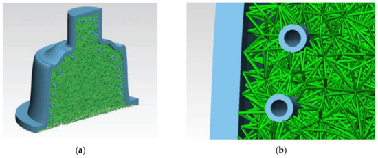
Figure 30.
A split mould tool with internal lattice structure in green (a) and a close view of the same mold (b) [143]. (a) Height = outer diameter = 200 mm. (b) Outer skin thickness = 6 mm and lattice structure = 0.5 mm [144].
7.3.3. Injection Molding: Case 3
As mentioned above, the implementation of conformal cooling channels to enhance the cooling efficiency has been the most common example of L-PBF design freedom in the injection molding sector and corresponding academic research. To benefit further from the L-PBF potential, the removal of excessive non-contributing material, topology optimization, should also be considered [145].
In this study, two topology optimization methods were considered and used [145]:
- A commercially available software, which adopts the geometry-based constraints and achieves a mass reduction of ≈50%.
- A topology optimization method developed in-house, which integrates a simplified AM process model within the standard topology optimization algorithm. The underlying thermal aspect of L-PBF is therefore included with a sequential localized steady-state thermal analysis and, thus, local overheating issues during manufacturing are avoided.
Figure 31 displays the original design of the studied injection molding insert. Figure 32 shows the “same” injection molding insert topology optimized with the standard density-based topology optimization (TO) algorithm and with the in-house novel TO algorithm with the AM thermal constraint (hotspot detection) [145]. The topology optimized inserts in Figure 32 have the same dimensions as the original, i.e., 220 mm × 110 mm × 25 mm. For simplicity, the authors display only half of each insert (110 mm × 110 mm × 25 mm) in Figure 32 [146].
The use of the novel in-house algorithm with the thermal AM constraint limits the occurrence of heat accumulation, local overheating and accumulated residual stresses, and results in a greater geometrical accuracy and surface quality [145].
The proposed algorithm that includes AM related thermal aspects indicates that there is room for further improvements [145].

Figure 31.
Original design of the injection molding insert [145].
Figure 31.
Original design of the injection molding insert [145].


Figure 32.
The injection molding insert, topology optimized with the standard density-based topology optimization (TO) algorithm and the in-house novel TO algorithm with AM thermal constraint (hotspot detection) [145]. The topology optimized inserts have the same dimensions as the original, Figure 31. For simplicity, the authors display only half of each insert (110 mm × 110 mm × 25 mm) in this figure [146].

8. Discussion
Three categories have been proposed for dividing the research in DfAM (design for additive manufacturing)—system design, part design, and process design [121]. The following selection criteria can be applied to identify whether a redesign for additive manufacturing would be beneficial [147]:
- Integrated design, the objective of which is to identify assemblies or groups of parts that can be re-designed into one single part.
- Individualization, which is driven by the wish to meet different customers’ needs.
- Lightweight design, where the reduced weight improves the performance of the product.
- Efficient design, the objective of which is to improve the efficiency and performance of the product (the tool in this paper) in operation.
The tooling examples in the previous section illustrate, emphasize the correctness of, and confirm the importance of using the system, part and process design approach and having efficient design as the selection criteria. Efficient design is of particular significance for the production tools in hot working and injection molding. The importance of process design and its close relationship to part and system design is illustrated in Figure 32 and [145].
While the primary target is high efficiency and performance in operation, using generative design and topology and lattice structure optimization will also lead to lightweight design.
Using the efficient design, i.e., high efficiency and performance in operation, as the criterion, the tooling examples in the previous section show that L-PBF (combined with conformal cooling and topology and lattice structure optimization) has its greatest potential in production tools for hot working and injection molding.
In injection molding, cooling stands for 60–90% of the total cycle time [143]. The related tooling examples in the previous section display the importance of efficient design. Conformal cooling channels in topology and lattice structure optimized inserts/core provide high efficiency and performance in injection molding.
In a 2003 review, design for layer manufacturing (LM) was identified as a topic that “required attention in the future”. To take full advantage of the design freedom offered by LM, the need for “research and development in the area of dedicated CAD design software incorporating design for LM modules” was highlighted [148]. Today, it is interesting to note the accuracy of this prediction.
In hot working, it is important to avoid thermal fatigue. The linear tensile or compressive stress that occurs in the tool can be calculated by [143]
in which σ = thermal stress developed due to the thermal change ΔT, Ti = initial temperature, Tf = final temperature, α = expansion coefficient and E = modulus of elasticity.
σ = α E (Ti − Tf ) = α E ΔT
Thermal fatigue is related to the parameter [143]
where σf = the mean fatigue strength and k = the thermal conductivity. An increase in this parameter indicates better resistance to thermal fatigue.
σfk/α E
Fast cooling by a large temperature difference ΔT will increase the thermal stress. Choosing a material with low α and E will decrease the thermal stresses, while an increased tensile strength will directly increase the effect the thermal stress has on the material.
AISI H13 has a thermal stress of σ = 2.604ΔT N/mm2 °C and a thermal conductivity of k = 27 W/mK at 500 °C. DIN 1.2709 has the properties σ = 2.124ΔT N/mm2 °C and k = 24 W/mK at 500 °C. Both steels have an almost equal ability to withstand thermal fatigue [143].
Samples tested with as-produced surface conditions usually show a poor fatigue life, since fatigue strength depends mostly on surface and internal defects. Therefore and for instance, surface machining improves fatigue properties considerably (in some cases to a comparable fatigue life as conventionally-produced specimens) [51]. See also [149].
H11 and H13 have superior wear resistance compared to 1.2709 [150]. As discussed in Section 5, the carbon-bearing H11 and H13 tend, however, to crack during L-PBF. Preheating the base plate, which lowers the thermal gradients and reduces the thermal stresses, has been identified as a measure to obtain crack-free H11 and H13 in L-PBF.
High tool efficiency and performance in operation is also affected by the corrosion properties in injection molding (of for instance reinforced polyamide). The corrosion properties of AM-produced steels, mainly stainless steels, is typically superior to those of conventionally produced material, mainly due to the fine microstructure and sometimes also due to the special texture and the two-phase nature of AM-produced stainless steels. The research into the reasons for the improved corrosion resistance is still in its early stages [51].
DIN 1.2709 (18Ni-300), the most established maraging grade, combines high values of mechanical properties (strength, hardness, toughness and ductility) with very good processability in L-PBF. However, due to the lack of chromium this steel grade does not exhibit corrosion resistance. The stainless steels 316L and 17-4PH are also well established as powder materials for additive manufacturing but have relatively low mechanical strength and hardness [151]. See also Table 7.
The recently developed M798 AMPO displays mechanical properties that are close to those of DIN 1.2709 but has better corrosion resistance than 17-4PH [151]. See also Table 7.
The recently developed AM Corrax displays also high strength and hardness, Table 7. Both untreated and surface treated AM Corrax samples were subject to corrosion tests, the salt spray testing and the cyclic polarization. The samples were surface treated with physical vapor deposition (PVD) coatings—TiN, CrN, and diamond-like carbon (DLC)—at temperatures below 450 °C, as well as with plasma nitriding treatments for conventional steel grades (PN1) and suitable for stainless steel grades (PN2). These tests showed that the corrosion resistance is high and can be summarized as untreated > PN2 > CrN > TiN > DLC > PN1 [152].
The number of powder steels for L-PBF of production tools is however very limited today, both in general and particularly for hot working (and injection molding). See Table 5, Table 6 and Table 7 and [51].
It was noted in the 2003 review that “a lot remains to be done to develop better base materials (powders, liquid photopolymers, etc.)…” for LM [148]. Metals, plastics, ceramics and composites are mentioned [148]. Many materials have been developed since then. However, the number of powder steels for L-PBF of production tools is, as noted above, still very limited.
As far as the feedstock (powder) is concerned, the metal powder should, according to some investigations, exhibit high sphericity, a clean and smooth surface, and low amount of satellites—features that are associated with gas-atomized powder [66]. The particle size distribution of the powder used in L-PBF is nominally 10–45 μm [65]. Some other investigations show that fine particles (D90 = 24.17 μm in the used powder) can easily be melted and are therefore beneficial for high part density and mechanical strength, while bigger particles (D90 = 55.54 μm in the used powder) are beneficial for higher breaking elongations. The selection of the appropriate particle size distribution must therefore take care of these contrary effects [153]. 316L is the powder material used in [66] and [153].
Water-atomized powder results in irregular shapes and low flowability but lower atomization costs. Water-atomized Fe-4800 powder has been successfully used to make objects by L-PBF. The low powder flowability was overcome through in-situ-alloying of carbon black nanoparticles in the range of 20–100 nm [154]. Compared to gas atomization, water atomization reduces the costs significantly. The costs will be discussed more later on in this section.
Spherical, ovoidal, and irregular particle shapes using powders atomized with argon, nitrogen and air (non-spherical N/air atomized powder were not possible to use before due to severe wiper blocking) have been successfully applied in L-PBF using nanoparticles as spacers. This process has been used for aluminium-silicon powder. However, since the principle of using nanoparticles is based on geometry, the same principle can be transferred to other material systems [155].
Research and development in the area of feedstock (powder) production and quality is therefore highly important from process, property, part quality, cost, and lead time perspectives.
Figure 33 displays a comparison of different metal AM methods with respect to part performance, cost and lot size. Production tools are normally made in single or few units and required to perform well in operation to avoid stops, minimize or eliminate rejections and maximize the production efficiency. L-PBF (PBF-L in Figure 33) is, other words, in a good position from these perspectives. The high L-PBF costs indicated in Figure 33 are observed in many AM tooling related investigations. See, for instance, [62,128].
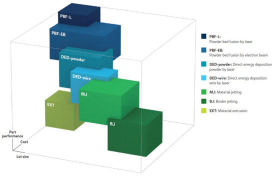
Figure 33.
A 2018 comparison of different metal AM methods with respect to part performance, cost and lot size [32].
For the parts that require production tooling, the costs of this tooling constitute an initial investment which in majority of the cases are larger for an AM inclusive process. However, the total cost per produced part can be reduced due to e.g., improved cooling and shorter cycle time using production tools made by an AM inclusive process [62], Figure 34.
For hot working and injection molding, the tools, dies, molds, cores and inserts made by L-PBF cost more but lead to lower total costs (the part costs) since such tools enable shorter cycle time, improved quality etc.
For cold working, both the tooling and part costs are, however, higher (than the conventionally made tool and the part made in it), in case the tools are made by L-PBF. A lead time reduction in toolmaking is reported particularly for the (cold) stamping tools made by an L-PBF inclusive process [62,128]. For (cold) stamping tools, the cost increase can in some cases be motivated by the significant lead time reduction. A so-called late change in the industrialization of a car body component can be considered as such a case.

Figure 34.
The part costs and revenues: conventional versus AM inclusive fabrication. The lower running AM costs is valid only for the cases in which the tooling enables a shorter cycle time, e.g., conformally cooled injection molding cores [62].
Figure 34.
The part costs and revenues: conventional versus AM inclusive fabrication. The lower running AM costs is valid only for the cases in which the tooling enables a shorter cycle time, e.g., conformally cooled injection molding cores [62].

The cost of feedstock (powder) production was mentioned above. The cost and productivity of L-PBF is closely related to the number of lasers that are active at the same time, Table 1. As displayed in this table, up to 12 lasers can be active at the same time. The costs for L-PBF have been reduced significantly during the past six years and will continue to fall in the coming years. However, these costs are still much higher than the costs for conventional toolmaking [32].
To accomplish a significant improvement of the process efficiency (productivity and cost), different technologies and methods need to be studied. As an example, the multi-spot array system based on multi-diode lasers can be mentioned. The machine design uses no scanner systems and instead relies on a printer head featuring several individually controllable diode lasers that is moved using linear axes [156]. See also [157].
It was noted in the 2003 review that productivity had been improved partially and that “a lot of effort is still required to further boost production rate” [148]. In addition, “exaggerated equipment and material cost” was observed due to the “great divergence of machines offered and their costs” [148]. The 2003 review concerned all LM methods (not only SLM/L-PBF). A great progress has been made since then. The build rate has improved significantly. In one of the current L-PBF machines, the build rate is 71 times higher than that in 1995. However, the productivity and cost need, as indicated above, to be improved further.
The 2003 review indicated “From near to net-shape” as another topic that “required attention in the future” [148]. Improved accuracy, repeatability and secured quality were mentioned in this context. “The combination with traditional processes in multiprocessing equipment might be explored” [148]. This topic has been addressed and a large progress has been made since 2003. However, post-processing is and will be an important topic also during the coming years.
In tooling applications, the roughness of the functional tool surfaces is of great significance. As mentioned in Section 5, L-PBF is not yet capable of providing the surface roughness required in tooling applications. The tool made by L-PBF needs therefore to be machined during post-processing to obtain the required surface roughness. Further improvement of L-PBF is, in other words, required in the future from this perspective. Laser surface re-melting might be a track to explore further to accomplish improved surface roughness.
Heat treatment is frequently needed in different tooling applications.
Multiprocessing equipment has been subject to exploration and will be important to explore further also in the future. Plants with a L-PBF inclusive production process, high degree of automation, digitization and digitalization is also a track that needs to be explored further in the future.
The size of the object than can be made by L-PBF is of great significance for many tooling applications. As mentioned in Section 3, the maximum object size that can be made by L-PBF today is 600 × 600 × 600 mm3 (although the largest height is 850 mm in one of the other current machines), Table 1. This size has more than doubled compared to that in the 1995 machine for SLS.
However, many production tools, particularly (cold) stamping, press-hardening, die casting tools are larger than 600 × 600 × 600 mm3. L-PBF can be used to make tool/die/mold inserts, which then are mounted in a core or shoe that is made by e.g., casting. Another option is to design the tool modularly and make each module by L-PBF. The object size that can be made by L-PBF will still be an important topic in the future. The challenge will then be to realize a homogenous shielding gas flow over the entire powder bed in combination with high productivity (due to the large object size).
According to a non-peer-reviewed assessment in 2018, metal AM is on the brink of industrialization [32]. The manufacturing readiness level (MRL) is the highest for L-PBF compared to the other metal AM methods [32]. According to another non-peer-reviewed assessment in 2020, L-PBF has reached the highest technology maturity index and the highest industrialization index (compared to other metal AM methods) and thereby a widespread industrial use [158]. L-PBF is almost fully industrialized [158]. Two other non-peer-reviewed assessments from 2013 and 2015 show that [159,160]
- dental/medical applications have reached the highest MRL (full- rate production),
- tooling applications the second highest MRL (low-rate production),
- aerospace industry the third highest MRL (capability in operational environment demonstrated—low rate production), and
- automotive industry the lowest MRL (technology validated in laboratory environment—basic capabilities shown).
The assessment in [160] is stated to be based on expert interviews.
In spite of this high MRL for L-PBF of tooling (low-rate production), further research and development is required to improve toolmaking by a L-PBF inclusive process: larger maximum objects sizes than be made by L-PBF, a larger number of powder metals that are designed for different tooling applications, lower feedstock (powder) costs, lower L-PBF processing costs, further L-PBF productivity and lead time improvement, minimized post-processing, improved surface roughness (both through L-PBF and in combination with efficient post-processing), and secured quality (including the L-PBF portion of the process). As indicated above, these improvements require research and development both within “single” topics, e.g., L-PBF in a multi-spot array system based on multi-diode lasers or laser re-melting, and from a toolmaking system view, e.g., plants with a high degree of automation and eventually cyber-physically controlled smart L-PBF inclusive manufacturing systems.
9. Summary and Conclusions
For laser-based powder bed fusion (L-PBF) of production tooling, the following summary and conclusions apply:
- Generative design and topology and lattice structure optimization enable, amplify and are a complement to the design freedom provided by L-PBF.
- A focus on efficient design, the objective of which is to improve the efficiency and performance of the tooling in operation, should be the primary target in tool design. Lightweight solutions can be obtained through topology and lattice structure optimization as a complement.
- Using high tooling efficiency and performance as the primary target, L-PBF exhibits the greatest potential for hot working and injection molding tools, dies and molds.
- The tools made by L-PBF cost more than those made conventionally. However, the total costs (the part costs) can be lower than those of the parts made in conventional tools, since the cycle time is reduced significantly in the tools made by L-PBF. Hot working and injection molding are the processes in which lower total costs can be obtained.
- For cold working, e.g., (cold) stamping, both the tooling and part costs are higher with tools made by L-PBF. However, the reported lead time reduction for toolmaking through L-PBF can be used to motivate higher tooling costs for e.g., the so-called late changes in the industrialization of car body components.
- The largest objects that can be made by L-PBF are currently 600 × 600 × 600 mm3 and 800 × 400 × 500 mm3.
- The number of metal powder alloys for tooling applications is limited. Currently, maraging steels 18Ni-300 (or DIN 1.2709) and M789 AMPO, stainless steels 316L, 17-4PH and 420, and the tool steels M2, H13, P20, and AM Corrax can be selected as tool material.
- According to some investigations, the metal powder should exhibit high sphericity, a clean and smooth surface, and low amount of satellites—features that are associated with inert gas atomization. The nominal particle size distribution used for L-PBF is 10–45 μm. Other investigations show that it is possible to L-PBF metal powder with irregular particle shapes—metal powder made by water or N/air atomization—successfully. This improves the resource efficiency, since larger percentages of atomized powder can be used in L-PBF.
- Laser power (W), scan velocity (mm/s), and hatch distance (mm) between neighboring melt tracks, and the layer thickness (μm) determine the process window in L-PBF.
- The path of the scan vector and thereby the scan strategy are essential for the final quality, i.e., defect types and numbers, microstructure, residual stresses, and surface roughness.
- A chess strategy (or island scanning) is effective in reducing the residual stresses.
- User experience and expertise play a large roll in some cases, e.g., selection of a scan strategy other than the one pre-set by the machine builder might lead to better dimensional accuracy and higher quality.
- The values of the process parameters and the size of the process window which provide fully dense and high quality objects in the above-mentioned metal powder tool materials can be found in this paper (Table 8).
- The downskin surface exhibits a roughness of 20–65 μm after L-PBF. For the upskin and the top surface, a roughness of 5 μm can be achieved in L-PBF. In other words, L-PBF is not yet capable of providing the surface roughness required in tooling applications. Smaller roughness requires post-processing by machining.
- The properties of the built object are anisotropic and dependent upon the build directions and angles.
- Faces with the downskin angle <45° require support structure.
- Internal channels should be built vertically.
- Several examples from different tooling applications in cold working, hot working and injection molding made by L-PBF are showcased in this paper.
- The corrosion properties of AM-produced steels, mainly stainless steels, are superior to those of the conventionally produced materials. The research into the reasons for the improved corrosion resistance is still in its early stages.
- The so-called carbon-free DIN 1.2709 obtains a ductile martensitic microstructure and is well processable in L-PBF, while the carbon-bearing H11 and H13 display a brittle martensitic microstructure that tends to crack due to the thermal stresses built up by the high cooling rates. A pre-heating of the base plate (building platform) eliminates, however, this cracking. H11 and H13 have superior wear resistance compared to DIN 1.2709. L-PBF yields excellent performance and is suitable for small lot sizes (in tooling, only a single or a few objects are made).
- According to non-peer-reviewed assessments, metal AM is on the brink of industrialization. The manufacturing readiness level is the highest for L-PBF compared to the other metal AM methods and the second highest for L-PBF of tooling (low-rate production) compared to L-PBF in other industrial/application segments.
- Rapid tooling has made a remarkable journey to AM of production tools by L-PBF thanks to the enormous efforts in research, development, entrepreneurial endeavors and company building.
- Further research and development is required to improve toolmaking by a L-PBF inclusive process: larger object sizes that can be made by L-PBF, a larger number of powder metals that are designed for different tooling applications, lower feedstock (powder) costs, lower L-PBF processing costs, further L-PBF productivity and lead time improvement, minimized post-processing, improved surface roughness (both through L-PBF and in combination with efficient post-processing) and secured quality (including the L-PBF portion of the process). These improvements require research and development both on “single” topics, e.g., L-PBF in a multi-spot array system based on multi-diode lasers, and from a toolmaking system view, e.g., plants with a high degree of automation and eventually cyber-physically controlled smart L-PBF inclusive manufacturing systems.
Funding
This research received no external funding.
Institutional Review Board Statement
Not applicable.
Informed Consent Statement
Not applicable.
Data Availability Statement
The data presented in this study are openly available in the referred publications. See the reference list.
Acknowledgments
The author expresses his sincere gratitude to Vegard Brøtan, SINTEF Manufacturing AS, Norway, Marc Fette, Airbus/CTC GmbH, Germany, Gerhard Hackl, ASMET, Austria, Professor Em. Jean-Pierre Kruth, KU Leuven, Belgium, Bernhard Langefeld, Roland Berger GmbH, Germany, Alexander Leicht, RISE Research Institutes of Sweden, Bernhard Mueller, Fraunhofer IWU, Germany, Professor Barbara Reggiani, UNIMORE, Italy, and Mirko Sinico, KU Leuven, Belgium, for providing valuable information and in some cases permissions.
Conflicts of Interest
The author declares no conflict of interest.
Appendix A
In this appendix, the methodology and process used to create and structure this review manuscript is described.
The purpose of this study was to conduct a review of the journey of the production tools for cold working, hot working and injection molding from rapid tooling to Additive Manufacturing (AM) by Laser-based Powder Bed Fusion (L-PBF).
To conduct this review, the keywords and the search profile were discussed with the university library staff resulting in the following search profile:
metals (”direct rapid tooling” OR ”metal additive manufacturing” OR ”laser powder bed fusion” OR ”selective laser melting” OR ”selective laser sintering”) (tools OR dies OR molds)
This search profile was then used in the available engineering databases at the university library: Materials Science and Engineering Database/Collection, Science Direct, Springer Link and Wiley Online.
Table A1.
The number of search results in the first step.
Table A1.
The number of search results in the first step.
| The Database | Number of Results |
|---|---|
| Materials Science and Engineering Collection | 401 |
| Science Direct | 5366 |
| Springer Link | 929 |
| Wiley Online | 972 |
| Total | 7668 |
To reduce the number of results, the obtained results (Table A1) were limited by using a number of selection criteria. Table A2 displays the used selection criteria per database and the number of the obtained results. See also Figure A1.
Table A2.
The selection criteria per database and the number of results. The indicated selection criteria were applied to the results obtained in the first step, i.e., Table A1.
Table A2.
The selection criteria per database and the number of results. The indicated selection criteria were applied to the results obtained in the first step, i.e., Table A1.
| The Database | Number of Results |
|---|---|
| Materials Science and Engineering Collection | |
| Peer-reviewed, English | 239 |
| Science Direct | |
| Open access, Procedia CIRP, Additive Manufacturing, Journal of Materials Processing Technology | 325 |
| Springer Link | |
| Subdiscipline Manufacturing, Machines, Tools, Processes, English | 212 |
| Wiley Online | |
| Journals, Advanced Engineering Materials, English | 112 |
| Total | 888 |
In step 3, the abstracts were reviewed and the duplications (or papers with “similar” contents), papers that were not related to direct rapid tooling, papers that were not related to production tools for cold working, hot working and injection molding, and the papers that were related to selective laser sintering (SLS) published after 2005 were removed. See also Figure A1.
In Step 4, the full papers were reviewed and
- similar papers were “neglected”, review papers were given a higher priority and industrial tooling applications were focused, and
- the remaining papers were classified based on Metallic materials for tooling applications, Design, simulations and modelling, Equipment for SLS/SLM/L-PBF, Process design and parameters, Properties and performance, and Examples of tooling applications.

Figure A1.
The method applied for creating this review.
Figure A1.
The method applied for creating this review.

The selected review targets at this stage were to
- set a baseline for the review by providing a brief historical background until 2005,
- provide the capabilities of the 2020 L-PBF equipment/machines,
- provide the chemical compositions and properties of the current materials for L-PBF of production tools in cold working, hot working and injection molding,
- describe the impact of feedstock and process parameters on the properties and performance,
- provide the L-PBF process parameters for the above-mentioned tool materials,
- provide a brief description of system, part and process design,
- review some examples of tooling applications designed for and made by L-PBF,
- discuss the advances made during the past 20 years and
- draw some conclusions.
Based on these selected targets, the remaining papers were kept in accordance with the above-mentioned classification.
In step 5, relevant standards were reviewed. The papers presented at some relevant conferences, such as the Tooling Conference, Metal Additive Manufacturing Conference (MAMC), and Solid Freeform Fabrication symposium (SFF) were selected based on the above-mentioned criteria and targets and reviewed. The websites of the material developers/producers and L-PBF machine builders were visited and the relevant material and machine information were gathered from these websites. A google search was conducted, the purpose of which was to find papers about the tooling materials mentioned above. These papers were then reviewed. The same classification was used for this information. See also Figure A1.
The review (manuscript) was then outlined based on the above-mentioned procedure and submitted. As this manuscript was peer-reviewed, the reviewers suggested:
- that items 4 and 6 above should be focused on tooling applications, and
- some improvements. To facilitate these improvements, the reviewers provided additional 10 publication titles.
These publications were reviewed and the manuscript was modified in accordance the reviewer suggestions.
As far as the machine builders are concerned, it is worth noting that Table 1 in the manuscript is limited to seven machine builders.
The present review manuscript does not comprise tools made by “conventional” powder metallurgy-based processes.
There is no bias in this review.
References
- Prinz, F.B.; Atwood, C.L.; Aubin, R.F.; Beaman, J.J.; Brown, R.L.; Fussel, P.S.; Lightman, A.J.; Sachs, E.; Weiss, L.E.; Wozny, M.J. Japanese and World Technology Evaluation Centers Panel Report on Rapid Prototyping in Europe and Japan; Analytical Chapters; Rapid Prototyping Association of the Society of Manufacturing Engineers: Baltimore, MD, USA, 1997; Volume 1, ISBN 1-883712-44-0. [Google Scholar]
- Matias, E.; Rao, B. 3D Printing: On Its Historical Evolution and the Implications for Business. In Management of the Technology Age, Proceedings of the PICMET ‘15 Conference, Portland International Center for Management of Engineering and Technology (PICMET), Portland, OR, USA, 2–6 August 2015; IEEE: Portland, OR, USA, 2015; pp. 551–558. [Google Scholar]
- Karapatis, N.P.; van Griethuysen, J.-P.S.; Glardon, R. Direct rapid tooling: A review of current research. Rapid Prototyp. J. 1998, 4, 77–89. [Google Scholar] [CrossRef]
- Kruth, J.-P. Rapid prototyping, a new application of physical and chemical processes for material accretion manufacturing. In Proceedings of the 11th International Symposium for Electromachining, Lausanne, Switzerland, 17–21 April 1995; pp. 3–28. [Google Scholar]
- Gebhardt, A. Rapid prototyping– laser-gestützte Revolution der Produktentwicklung. Laser Magazin 1996, 1, 6–9. [Google Scholar]
- Wohlers, T. Rapid Prototyping State of the Industry: 1995–96 Worldwide Progress Report; Society of Manufacturing Engineers Symposium: Dearborn, MI, USA, April 1996. [Google Scholar]
- Styger, L. Rapid Prototyping and Tooling: The Enabling Technology of the ‘90s. IEE Manufacturing Division Colloquium on Rapid Prototyping in the UK: Coventry, UK, 1994. [Google Scholar]
- Rapid Prototyping: Rewriting the Rule Book; IEE Manufacturing Division Colloquium on Rapid Prototyping in the UK: Coventry, UK, 1994.
- CRIF-Liège Information Leaflet; CRIF: Liège, Belgium, 1996.
- Lohner, A. Laser sintering ushers in new route to PM parts. Metal Powder Rep. 1997, 52, 24–30. [Google Scholar]
- Girouard, D. The SLSTM selective laser sintering process: Technology, applications, and materials for advanced rapid prototyping. In Proceedings of the IBEC ‘93, Detroit, MI, USA, 21–23 September 1993; pp. 10–14. [Google Scholar]
- Shellabear, M.; Nyrhilä, O. Dmls—Development history and state of the art. In Proceeding of the 4th LANE (Laser Assisted Net Shape Engineering), Erlangen, Germany, 21–24 September 2004. [Google Scholar]
- Wohler, T.; Gornet, T. History of additive manufacturing. Wohler Rep. 2016, 24, 118. [Google Scholar]
- Hejmadi, U.; McAlea, K. Selective laser sintering of metal molds: The RapidToolTM process. In Proceedings of the Annual International Solid Freeform Fabrication Symposium, Austin, TX, USA, 12–14 August 1996; pp. 97–104. [Google Scholar]
- Nyrhilä, O.; Syrjälä, S. Manufacture of Dimensionally Precise Pieces by Sintering. U.S. Patent 5,061,439, 5 December 1990. [Google Scholar]
- Holger, D.; Pilz, R.; Eleser, N.S. Rapid tooling of EDM electrodes by means of selective laser sintering. Comput. Ind. 1999, 39, 35–45. [Google Scholar]
- Majewski, C.; Hopkinson, N. The Effect of Layer Thickness on Ejection Forces for Injection Moulded Parts Made Using DMLS Tools. In Proceedings of the Annual International Solid Freeform Fabrication Symposium, Austain, TX, USA, 5–7 August 2002; pp. 73–82. [Google Scholar]
- King, D.; Tansey, T. Rapid tooling: Selective laser sintering injection tooling. J. Mater. Process. Technol. 2003, 132, 42–48. [Google Scholar] [CrossRef]
- Kruth, J.-P.; Mercelis, P.; Van Vaerenbergh, J.; Froyen, L.; Rombouts, M. Advances in selective laser sintering. In Proceedings of the 1st International Conference on Advanced Research in Virtual and Rapid Prototyping (VR@P), Leiria, Portugal, 1–4 October 2003; pp. 59–69. [Google Scholar]
- Meiners, W.; Wissenbach, K.; Gasser, A. Selective Laser Sintering at Melting Temperature. U.S. Patent 6,215,093, 10 April 2001. [Google Scholar]
- Neikov, O.D. Powders for Metal Additive Processing. In Handbook for Non-Ferrous Metal Powders—Technologies and Applications, 2nd ed.; Neikov, O.D., Naboychenko, S.S., Yefimov, N.A., Eds.; Elsevier: Amsterdam, The Netherlands, 2019; pp. 373–399. ISBN 978-0-08-100543-9. [Google Scholar]
- Meiners, W.; Over, C.; Wissenbach, K.; Poprawe, R. Direct Generation of Metal Parts and Tools by Selective Laser Powder Remelting (SLPR). In Proceedings of the Annual International Solid Freeform Fabrication Symposium, Austain, TX, USA, 9–11 August 1999; pp. 655–661. [Google Scholar]
- Kruth, J.-P.; Vandenbroucke, B.; Van Vaerenbergh, J.; Mercelis, P. Benchmarking of different sls/slm processes as rapid manufacturing techniques. In Proceeding of International Conference Polymers & Moulds Innovations (PMI), Gent, Belgium, 20–23 April 2005; pp. 1–7. [Google Scholar]
- Sprinkle, T. The 5 Most Important Standards in Additive Manufacturing. ASTM Standardization News. 11 May 2020. Available online: https://www.astm.org/standardization-news/?q=features/5-most-important-standards-additive-manufacturing-.html (accessed on 25 November 2020).
- ISO. International Standard ISO 52900, 2016—Additive manufacturing—General principles—Terminology (ISO/ASTM 52900, 2015, IDT); ISO: Geneva, Switzerland, 2016. [Google Scholar]
- ISO. International Standard ISO 17296-2, 2016—Additive manufacturing—General principles—Part 2, Overview of process categories and feedstock (ISO 17296-2, 2015); ISO: Geneva, Switzerland, 2016. [Google Scholar]
- Ålgårdh, J.; Strondl, A.; Karlsson, S.; Farre, S.; Joshi, S.; Andersson, J.; Ågren, J. State-of-the-Art for Additive Manufacturing of Metals; Report 2016-03898—State-of-the-Art—Version 2.1; Swedish Arena for Additive Manufacturing of Metals: Stockholm, Sweden, 2017. [Google Scholar]
- Criales, L.E.; Arısoy, Y.M.; Lane, B.; Moylan, S.; Donmez, A.; Özel, T. Laser powder bed fusion of nickel alloy 625, Experimental investigations of effects of process parameters on melt pool size and shape with spatter analysis. Int. J. Mach. Tool Manuf. 2017, 121, 22–36. [Google Scholar] [CrossRef]
- Schwarze, D. Auswirkungen der Bauraumvorheizung auf die thermomechanischen Bauteileigenschaften; Anwender Zentrum Augsburg, IWB: München, Germany, 2010. [Google Scholar]
- Over, C. Generative Fertigung von Bauteilen aus Werkzeugstahl X38CrMoV5-1 und Titan TiAl6V4 mit “Selective Laser Melting”; Shaker: Aachen, Germany, 2003. [Google Scholar]
- Niendorf, T.; Leuders, S.; Riemer, A.; Richard, H.A.; Tröster, T.; Schwarze, D. Highly Anisotropic Steel Processed by Selective Laser Melting. Metall. Mater. Trans. B 2013, 44B, 794–796. [Google Scholar] [CrossRef]
- Langefeld, B.; Moehrle, M.; Balzer, C.; Schildbach, P. Advancements in Metal 3D Printing—Beyond Powder Bed—Additive Manufacturing on the Brink of Industrialization; Roland Berger: Munich, Germany, 2018. [Google Scholar]
- 3D Systems, Printers and Materials Specifications. Available online: https://www.3dsystems.com (accessed on 27 November 2020).
- Additive Industries, Printers and Materials Specifications. Available online: https://www.additiveindustries.com (accessed on 27 November 2020).
- Concept Laser, Printers and Materials Specifications. Available online: https://www.ge.com/additive/who-we-are/concept-laser (accessed on 27 November 2020).
- EOS (Electro Optical Systems), Printers and Materials Specifications. Available online: https://www.eos.info/en (accessed on 27 November 2020).
- SLM Solutions, Printers and Materials Specifications. Available online: https://www.slm-solutions.com/ (accessed on 27 November 2020).
- Renishaw, Printers and Materials Specifications. Available online: https://www.renishaw.com/en/metal-3d-printing--32084 (accessed on 27 November 2020).
- Trumpf, Printers and Materials Specifications. Available online: https://www.trumpf.com/en_INT/products/machines-systems/additive-production-systems (accessed on 27 November 2020).
- Liljengren, M.; Kjellsson, K.; Johansson, T.; Asnafi, N. Die Materials, Hardening Methods and Surface Coatings for Forming of High, Extra High & Ultra High Strength Steel Sheets (HSS/EHSS/UHSS). In Proceedings of the Annual Conference of the International Deep Drawing Research Group’s (IDDRG), Porto, Portugal, 19–21 June 2006; pp. 507–603. [Google Scholar]
- Asnafi, N.; Johansson, T.; Miralles, M.; Ullman, A. Laser Surface-Hardening of Dies for Cutting, Blanking or Trimming of Uncoated DP600. Proceeding of the Recent Advances in Manufacture & Use of Tools & Dies and Stamping of Steel Sheets, Olofström, Sweden, 5–6 October 2004; pp. 169–190. [Google Scholar]
- Asnafi, N. Tooling and Technologies for Processing of Ultra High Strength Sheet Steels. In Proceedings of the Tools and Technologies for Processing Ultra High Strength Materials, Graz University of Technology, Graz, Austria, 19–21 September 2011. [Google Scholar]
- Sjöström, J. Chromium Martensitic Hot-Work Tool Steels—Damage, Performance and Microstructure. Ph.D. Thesis, Karlstad University Studies, Karlstad, Sweden, 2004; p. 52, ISBN 91-85335-21-5. [Google Scholar]
- Fuchs, K.-D. Hot-Work Tool Steels with Improved Properties for Die casting Applications. In Proceedings of the 6th International Conference on Tooling, Karlstad, Sweden, 10–13 September 2002; pp. 17–26. [Google Scholar]
- Klobčar, D.; Tušek, J.; Taljat, B. Thermal fatigue of materials for die-casting tooling. Mater. Sci. Eng. A 2008, 472, 198–207. [Google Scholar] [CrossRef]
- Vasco, J.; Capela, C.; Bártolo, P.; Granja, D. Material Selection for High Performance Moulds. In Proceedings of the SPE Meeting Improving Quality and Tool Efficiency within Injection Moulding K2007, Düsseldorf, Germany, 25 October 2007; pp. 1–7. [Google Scholar]
- Rebeggiani, S. On Polishability of Tool Steels; Chalmers University of Technology: Göteborg, Sweden, 2013; ISBN 978-91-7385-828-1. [Google Scholar]
- Roberts, G.; Krauss, G.; Kennedy, R. Tool Steels, 5th ed.; ASM International: Novelty, OH, USA, 1998; ISBN 978-0-87170-599-0. [Google Scholar]
- Højerslev, C. Tool steels. Risoe-R, No. 1244(EN); Risø National Laboratory, Forskningscenter Risoe: Roskilde, Denmark, 2001. [Google Scholar]
- The online Material Properties Database MakeItFrom.com. Available online: https://www.makeitfrom.com (accessed on 12 September 2020).
- Bajaj, P.; Hariharan, A.; Kini, A.; Kürnsteiner, P.; Raabe, D.; Jägle, E.A. Steels in additive manufacturing: A review of their microstructure and properties. Mater. Sci. Eng. A 2020, 772, 138633. [Google Scholar] [CrossRef]
- Böhler Edelstahl, Material Specifications. Available online: https://www.bohler-edelstahl.com/en/applications/3d-printing-selective-laser-melting/ (accessed on 27 November 2020).
- FORMETRIX, L-40 Specification. Available online: https://www.formetrixmetals.com/products/formetrix-l-40/ (accessed on 27 November 2020).
- Eriksson, P. Evaluation of Mechanical and Microstructural Properties for Laser Powder-Bed Fusion 316L; Uppsala University: Uppsala, Sweden, 2018. [Google Scholar]
- Zai, L.; Zhang, C.; Wang, Y.; Guo, W.; Wellmann, D.; Tong, X.; Tian, Y. Laser Powder Bed Fusion of Precipitation-Hardened Martensitic Stainless Steels: A Review. Metals 2020, 10, 255. [Google Scholar] [CrossRef]
- Nath, S.D.; Irrinki, H.; Gupta, G.; Kearns, M.; Gulsoy, O.; Are, S. Micostructure-property relationships of 420 stainless steel fabricated by laser-power bed fusion. Powder Technol. 2019, 343, 738–746. [Google Scholar] [CrossRef]
- Zhao, X.; Wei, Q.; Song, B.; Liu, Y.; Luo, X.; Wen, S.; Shi, Y. Fabrication and Characterization of AISI 420 Stainless Steel Using Selective Laser Melting. Mater. Manuf. Process. 2015, 30, 1283–1289. [Google Scholar] [CrossRef]
- Kempen, K.; Vrancken, B.; Buls, S.; Thijs, L.; Van Humbeek, J.; Kruth, J.-P. Selective Laser Melting of Crack-Free High Density M2 High Speed Steel Parts by Baseplate Preheating. J. Manuf. Sci. Eng. 2014, 136, 061026-1. [Google Scholar] [CrossRef]
- Mazur, M.; Brincat, P.; Leary, M.; Brandt, M. Numerical and experimental evaluation of conformally cooled H13 steel injection mould manufactured with selective laser melting. Int. J. Adv. Manuf. Technol. 2017, 93, 881–900. [Google Scholar] [CrossRef]
- Li, H.X.; Qi, H.L.; Song, C.H.; Li, Y.L.; Yan, M. Selective laser melting of P20 mould steel: Investigation on the resultant microstructure, high-temperature hardness and corrosion resistance. Powder Metall. 2018, 61, 21–27. [Google Scholar] [CrossRef]
- Uddeholm, AM Corrax Specification. Available online: https://www.uddeholm.com/sweden/sv/products/uddeholm-am-corrax (accessed on 27 November 2020).
- Asnafi, N.; Rajalampi, J.; Aspenberg, D.; Alveflo, A. Production Tools Made by Additive Manufacturing Through Laser-based Powder Bead Fusion. Berg Huettenmaenn Mon. 2020, 165, 125–136. [Google Scholar] [CrossRef]
- Mooney, B.; Kourousis, K.I. A Review if Factors Affecting the Mechanical Properties of Maraging Steel 300 Fabricated via Laser Powder Bed Fusion. Metals 2020, 10, 1273. [Google Scholar] [CrossRef]
- Vock, S.; Klöden, B.; Kirchner, A.; Weißgärber, T.; Kieback, B. Powders for powder bed fusion: A review. Prog. Addit. Manuf. 2019, 4, 383–397. [Google Scholar] [CrossRef]
- Sames, W.J.; List, F.A.; Pannala, S.; Dehoff, R.R.; Babu, S.S. The metallurgy and processing science of metal additive manufacturing. Int. Mater. Rev. 2016, 61, 315–360. [Google Scholar] [CrossRef]
- Leicht, A. Aspects of Building Geometry and Powder Characteristics in Powder Bed Fusion; Tech Technical report no. IMS-2018-1; Ph.D. Thesis; Chalmers University of Technology: Göteborg, Sweden, 2018. [Google Scholar]
- Li, R.; Shi, Y.; Wang, Z.; Wang, L.; Liu, J.; Jiang, W. Densification behavior of gas and water atomized 316 L stainless steel powder during selective laser melting. Appl. Surface Sci. 2010, 256, 4350–4356. [Google Scholar] [CrossRef]
- Hoeges, S.; Zwiren, A.; Schade, C. Additive manufacturing using water atomized steel powders. Metal Powder Rep. 2017, 72, 111–117. [Google Scholar] [CrossRef]
- Abdelwahed, M.; Casati, R.; Bengtsson, S.; Larsson, A.; Riccio, M.; Vedani, M. Effects of Powder Atomization on Microstructural and Mechanical Behaviour of L-PBF Processed Steels. Metals 2020, 10, 1474. [Google Scholar] [CrossRef]
- ASTM. F3049-14 Standard Guide for Characterizing Properties of Metal Powders Used for Additive Manufacturing Processes; ASTM International: West Conshohocken, PA, USA, 2014. [Google Scholar]
- Spierings, A.B.; Voegtlin, M.; Bauer, T.; Wegener, K. Powder flowability characterization methodology for powder-bed-based metal additive manufacturing. Prog. Addit. Manuf. 2016, 1, 9–20. [Google Scholar] [CrossRef]
- A Guidebook to Particle Size Analysis. Horiba Scientific. Available online: https://www.horiba.com (accessed on 27 November 2020).
- Karg, M.C.H.; Hentschel, O.; Ahuja, B.; Junker, D.; Hassler, U.; Schäperkötter, C.S.; Haimerl, A.; Arnet, H.; Merklein, M.; Schmidt, M. Comparison of process characteristics and resulting microstructure of maraging steel 1.2709 in Additive Manufacturing via Laser Metal Deposition and Laser Beam Melting in Powder Bed. In Proceedings of the 6th International Conference on Additive Technologies, ICAT2016, Nürnberg, Germany, 29–30 November 2016; pp. 39–50. [Google Scholar]
- Oliveira, J.P.; LaLonde, A.D.; Ma, J. Processing parameters in laser powder bed fusion metal additive manufacturing. Mater. Design 2020, 193, 108762. [Google Scholar] [CrossRef]
- Metens, R.; Dadbakhsh, S.; Van Humbeeck, J.; Kruth, J.-P. Application of base plate preheating during selective laser melting. Procedia CIRP 2018, 74, 5–11. [Google Scholar] [CrossRef]
- Leicht, A. Laser Powder Bed Fusion of 316L Stainless Steel—Microstructure and Mechanical Properties as a Function of Process Parameters, Design and Productivity. Ph.D. Thesis, Chalmers University of Technology, Göteborg, Sweden, 2020. ISBN 978-91-7905-289-8. [Google Scholar]
- Ali, H.; Ghadbeigi, H.; Mumtaz, K. Effect of scanning strategies on residual stress and mechanical properties of Selective Laser Melted Ti6Al4V. Mater. Sci. Eng. A 2018, 712, 175–187. [Google Scholar] [CrossRef]
- Bartlett, J.L.; Li, X. An overview of residual stresses in metal powder bed fusio. Addit. Manuf. 2019, 27, 131–149. [Google Scholar]
- Saunders, M. How process parameters drive successful metal ALM part production. Metal AM 2018, 4, 127–135. [Google Scholar]
- Kou, S. Welding Metallurgy, 2nd ed.; John Wiley & Sons: Hoboken, NJ, USA, 2003. [Google Scholar]
- Wang, Z.; Denlinger, E.; Michaleris, P.; Stoica, A.D.; Ma, D.; Beese, A.M. Residual stress mapping in Inconel 625 fabricated through additive manufacturing: Method for neutron diffraction measurements to validate thermomechanical model predictions. Mater. Design 2017, 11, 3169–3177. [Google Scholar] [CrossRef]
- Rodrigues, T.A.; Duarte, V.; Avila, J.A.; Santos, T.G.; Miranda, R.; Oliveira, J. Wire and arc additive manufacturing of HSLA steel: Effect of thermal cycles on microstructure and mechanical properties. Addit. Manuf. 2019, 27, 440–450. [Google Scholar] [CrossRef]
- Bobbio, L.D.; Bocklund, B.; Otis, R.; Borgonia, J.P.; Dillon, R.P.; Shapiro, A.A.; McEnerney, B.; Liu, Z.-K.; Beese, A.M. Characterization of a functionally graded material of Ti-6Al-4V to 304L stainless steel with an intermediate V section. J. Alloys Compd. 2018, 742, 1031–1036. [Google Scholar] [CrossRef]
- Carroll, B.E.; Otis, R.A.; Borgonia, J.P.; Suh, J.O.; Dillon, R.P.; Shapiro, A.A.; Hofmann, D.C.; Liu, Z.K.; Beese, A.M. Functionally graded material of 304L stainless steel and inconel 625 fabricated by directed energy deposition: Characterization and thermodynamic modeling. Acta Mater. 2016, 108, 46–54. [Google Scholar] [CrossRef]
- DebRoy, T.; Wei, H.L.L.; Zuback, J.S.S.; Mukherjee, T.; Elmer, J.W.W.; Milewski, J.O.O.; Beese, A.M.M.; Wilson-Heid, A.; De, A.; Zhang, W. Additive manufacturing of metallic components—Process, structure and properties. Prog. Mater. Sci. 2018, 92, 112–224. [Google Scholar] [CrossRef]
- Dai, D.; Gu, D. Effect of metal vaporization behavior on keyhole-mode surface morphology of selective laser melted composites using different protective atmospheres. Appl. Surface Sci. 2015, 355, 310–319. [Google Scholar] [CrossRef]
- Zhong, Y.; Liu, L.; Wikman, S.; Cui, D.; Shen, Z. Intragranular cellular segregation network structure strengthening 316L stainless steel prepared by selective laser melting. J. Nucl. Mater. 2016, 470, 170–178. [Google Scholar] [CrossRef]
- Kluczyński, J.; Śnieżek, L.; Grzelak, K.; Janiszewski, J.; Płatek, P.; Torzewski, J.; Szachogłuchowicz, I.; Gocman, K. Influence of Selective Laser Melting Technological Parameters on the Mechanical Properties of Additively Manufactured Elements Using 316L Austenitic Steel. Materials 2020, 13, 1449. [Google Scholar] [CrossRef] [PubMed]
- Burns, D.E.; Kudzal, A.; McWilliams, B.; Manjarres, J.; Hedges, D.; Parker, P.A. Investigating Additively Manufactured 17-4 PH for Structural Applications. J. Mater. Eng. Perform. 2019, 28, 4943–4951. [Google Scholar] [CrossRef]
- Irrinki, H.; Dexter, M.; Barmore, B.; Enneti, R.; Pasebani, S.; Badwe, S.; Stitzel, J.; Malhotra, R.; Are, S. Effects of Powder Attributes and Laser Powder Bed Fusion (L-PBF) Process Conditions on the Densification and Mechanical Properties of 17-4 PH Stainless Steel. JOM 2016, 68, 860–868. [Google Scholar] [CrossRef]
- Yan, J.; Zhou, Y.; Gu, R.; Zhang, X.; Quach, W.-M.; Yan, M. A Comparison Study of Steel Powders (316L, H13, P20 and 18Ni300) for Their Selective Melting Additive Manufacturing. Metals 2019, 9, 86. [Google Scholar] [CrossRef]
- Turk, C.; Zunko, H.; Aumayr, C.; Leitner, H.; Kapp, M. Advances in Maraging Steels for Additive Manufacturing. Berg-und Hüttenmännische Mon. 2019, 164, 112–116. [Google Scholar] [CrossRef]
- Jiang, J.; Chen, J.; Ren, Z.; Mao, Z.; Ma, X.; Zhang, D.Z. The influence of Process Parameters and Scanning Strategy on Lower Surface Quality of TA 15 Parts Fabricated by Selective Laser Melting. Metals 2020, 10, 1228. [Google Scholar] [CrossRef]
- Chen, Z.; Wu, X.; Tomus, D.; Davies, C.H.J. Surface roughness of Selective Laser Melted Ti-6Al-4V alloy components. Addit. Manuf. 2018, 21, 91–103. [Google Scholar] [CrossRef]
- Snyder, J.C.; Thole, K.A. Understanding Laser Powder Bed Fusion Surface Roughness. J. Manuf. Sci. Eng. 2020, 142, 71003. [Google Scholar] [CrossRef]
- Wang, D.; Liu, Y.; Yang, Y. Theoretical and experimental study on surface roughness of 316L stainless steel metal parts obtained through selective laser melting. Rapid Prototyp. J. 2016, 22, 706–716. [Google Scholar] [CrossRef]
- Spierings, A.B.; Levy, G. Comparison of density of stainless steel 316L parts produced with selective laser melting using different powder grades. In Proceedings of the Annual International Solid Freeform Fabrication Symposium, Austin, TX, USA, 3–5 August 2009; pp. 342–353. [Google Scholar]
- Yang, T.; Liu, T.; Liao, W.; Macdonald, E.; Wei, H.; Chen, X. The Influence of Process Parameters on Vertical Surface Roughness of the AlSi10Mg Parts Fabricated by Selective Laser Melting. J. Mater. Process. Technol. 2019, 266, 26–36. [Google Scholar] [CrossRef]
- Casalino, G.; Campanelli, S.L.; Contuzzi, N.; Ludovico, A.D. Experimental Investigation and Statistical Optimisation of the Selective Laser Melting Process of a Maraging Steel. Opt. Laser Technol. 2015, 65, 151–158. [Google Scholar] [CrossRef]
- Liu, B.; Wildman, R.; Tuck, C.; Ashcroft, I.; Hague, R. Investigation the Effect of Particle Size Distribution on Processing Parameters Optimisation in Selective Laser Melting Process. In Proceedings of the Annual International Solid Freeform Fabrication Symposium, University of Texas at Austin, Austin, TX, USA, 8–10 August 2011; pp. 227–238. [Google Scholar]
- Sendino, S.; Martinez, S.; Lartategui, F.; Diaz, J.; Lamikiz, A.; Ukar, E. Surface Roughness Dependant Factors in Metal Bed Fusion Processes. In Proceedings of the Joint Special Interest Group meeting between euspen (the European Society for Precision Engineering and Nanotechnology) and ASPE (the American Society of Precision Engineering) on Advancing Precision in Additive Manufacturing, Ecole Centrale de Nantes, Nantes, France, 16–18 September 2019. [Google Scholar]
- Moylan, S.; Slotwinski, J.; Cooke, A.; Jurrens, K.; Donmez, M.A. An Additive Manufacturing Test Artifact. J. Res. Natl. Inst. Stand. Technol. 2014, 119, 429–459. [Google Scholar] [CrossRef] [PubMed]
- Rebaioli, L.; Fassi, I. A review on benchmark artifacts for evaluating the geometrical performance of additive manufacturing processes. Int. J. Adv. Manuf. Technol. 2017, 93, 2571–2598. [Google Scholar] [CrossRef]
- Moshiri, M.; Tosello, G.; Mohanty, S. A new design for an extensive benchmarking of additive manufacturing machines. In Proceedings of the 18th International Conference of the European Society for Precision Engineering and Nanotechnology (Euspen 18), Venice, Italy, 4–8 June 2018. [Google Scholar]
- Moshiri, M.; Candeo, S.; Carmignato, S.; Mohanty, S.; Tosello, G. Benchmarking of Laser Powder Bed Fusion Machines. J. Manuf. Mater. Process. 2019, 3, 85. [Google Scholar] [CrossRef]
- Tomas, J.; Hitzler, L.; Köller, M.; von Kobylinski, J.; Sedlmajer, M.; Werner, E.; Merkel, M. The Dimensional Accuracy of Thin-Walled Parts Manufactured by Laser-Powder Bed Fusion Process. J. Manuf. Mater. Process. 2020, 4, 91. [Google Scholar] [CrossRef]
- Krish, S. A practical generative design method. Comput. Aided Des. 2011, 43, 88–100. [Google Scholar] [CrossRef]
- Briard, T.; Segonds, F.; Zamariola, N. G-DfAM: A methodological proposal of generative design for additive manufacturing in the automotive industry. Int. J. Interact. Des. Manuf. 2020, 14, 875–886. [Google Scholar] [CrossRef]
- Bendsoe, M.P.; Sigmund, O. Topology Optimization: Theory, Methods and Applications; Springer: Berlin/Heidelberg, Germany, 2004. [Google Scholar]
- Liu, X.; Yi, W.J.; Li, Q.S.; Shen, P.S. Genetic evolutionary structural optimization. J. Constr. Steel Res. 2008, 64, 305–311. [Google Scholar] [CrossRef]
- Zhao, F. A nodal variable ESO (BESO) method for structural topology optimization. Finite Elem. Anal. Des. 2014, 86, 34–40. [Google Scholar] [CrossRef]
- Guo, X.; Zhang, W.; Zhang, J.; Yuan, J. Explicit structural topology optimization based on moving morphable components (MMC) with curved skeletons. Comput. Methods Appl. Mech. Eng. 2016, 310, 711–748. [Google Scholar] [CrossRef]
- Niendorf, T.; Brenne, F.; Schaper, M. Lattice Structures Manufactured by SLM: On the Effect of Geometrical Dimensionson Microstructure Evolution During Processing. Metall. Mater. Trans. B 2014, 45B, 1181–1185. [Google Scholar] [CrossRef]
- Schnabel, T.; Oettel, M.; Mueller, B.; Hoschke, K.; Pfaff, A.; Amund-Kopp, C.; Klöden, B.; Gebauer, M.; Töppel, T. Design for Additive Manufacturing, Guidelines and Case Studies for Metal Applications; Fraunhofer IWU, EMI and IFAM: Dresden, Germany, 2017. [Google Scholar]
- Pan, C.; Han, Y.; Lu, J. Design and Optimization of Lattuce Structures: A Review. Appl. Sci. 2020, 10, 6374. [Google Scholar] [CrossRef]
- Dong, G.; Tang, Y.; Zhao, Y.F. A Survey of Modeling of Lattice Structures Fabricated by Additive Manufacturing. J. Mech. Des. 2017, 139, 100906. [Google Scholar] [CrossRef]
- Kuo, T.C.; Huang, S.H.; Zhang, H.C. Design for manufacture and design for ‘X’: Concepts, applications, and perspectives. Comput. Ind. Eng. 2001, 41, 241–260. [Google Scholar] [CrossRef]
- Tomiyama, T.; Gu, P.; Jin, Y.; Lutters, D.; Kind, C.; Kimura, F. Design methodologies: Industrial and educational applications. CIRP Ann. Manuf. Technol. 2009, 58, 543–565. [Google Scholar] [CrossRef]
- Laverne, F.; Segonds, F.; Answer, N.; Le Coq, M. Assembly Based Methods to Support Product Innovation in Design for Additive Manufacturing: An Exploratory Case Study. J. Mech. Des. 2015, 137, 121701. [Google Scholar] [CrossRef]
- Reiher, T.; Lindemann, C.; Jahnke, U.; Deppe, G.; Koch, R. Holistic approach for industrializing AM technology: From part selection to test and verification. Prog. Addit. Manuf. 2017, 2, 43–55. [Google Scholar] [CrossRef]
- Wiberg, A.; Persson, J.; Ölvander, J. Design for additive manufacturing—A review of available design methods and software. Rapid Prototyp. J. 2019, 25, 1080–1094. [Google Scholar] [CrossRef]
- VDI. VDI Guideline 3405 Part 2—Additive Manufacturing Processes, Rapid Manufacturing—Beam Melting of Metallic Parts—Qualification, Quality Assurance and Post Processing; VDI: Düsseldorf, Germany, 2013. [Google Scholar]
- International Standard ISO/ASTM 52911-1. Additive Manufacturing—Design—Part 1, Laser-Based Powder Bed Fusion of Metals; ISO: Geneva, Switzerland, 2019. [Google Scholar]
- Reinarz, B.; Sehrt, J.T.; Witt, G.; Deiss, O.; van Kampen, J.; Münzer, J.; Ott, M. Optimization of media feed channels in laser beam melting. Proc. ASPE. Berkeley 2014, 57, 13–18. [Google Scholar]
- Hitzler, L.; Hirsch, J.; Heine, B.; Merkel, M.; Hall, W.; Öchsner, A. On the Anisotropic Mechanical Properties of Selective Laser-Melted Stainless Steel. Materials 2017, 10, 1136. [Google Scholar] [CrossRef] [PubMed]
- Li, R.; Kim, Y.S.; Tho, H.V.; Yum, Y.J.; Kim, W.J.; Yang, S.Y. Additive manufacturing (AM) of piercing punches by the PBF method of metal 3D printing using mold steel powder materials. J. Mech. Sci. Technol. 2019, 33, 809–817. [Google Scholar] [CrossRef]
- Zelený, P.; Váňa, T.; Stryal, J. Application of 3D Printing for Specific Tools. Mater. Sci. Forum 2016, 862, 316–323. [Google Scholar] [CrossRef]
- Leal, R.; Barreiros, F.M.; Alves, L.; Romeiro, F.; Vasco, J.C.; Santos, M. Additive manufacturing tooling for the automotive industry. Int. J. Adv. Manuf. Technol. 2017, 92, 1671–1676. [Google Scholar] [CrossRef]
- Asnafi, N.; Shams, T.; Aspenberg, D.; Öberg, C. 3D Metal Printing from an Industrial Perspective—Product Design, Production and Business Models. BHM Berg-und Hüttenmännische Mon. 2019, 164, 91–100. [Google Scholar] [CrossRef]
- Aspenberg, D.; Asnafi, N. Topology optimization of a U-bend tool using LS-TaSC. In Proceedings of the 12th European LS-DYNA Conference, Koblenz, Germany, 14–16 May 2019. [Google Scholar]
- Asnafi, N.; Rajalampi, J.; Aspenberg, D. Design and Validation of 3D-Printed Tools for Stamping of DP600. In Proceedings of the IOP Conference Series: Materials Science and Engineering, 3–7 June 2019; Volume 651, p. 12010. [Google Scholar]
- Skåre, T.; Asnafi, N. Forming and trimming of 2-mm thick DP600 sheet steel in tools and dies 3D-printed in maraging steel by laser-based powder bed fusion. In Proceedings of the IOP Conference Series: Materials Science and Engineering, 26–30 October 2020; Volume 67, p. 12040. [Google Scholar]
- Müller, B.; Gebauer, M.; Hund, R.; Malek, R.; Gerth, N. Metal Additive Manufacturing for tooling applications—Laser Beam Melting technology increases efficiency of dies and molds. In Proceedings of the Metal Additive Manufacturing Conference 2014 (MAMC 2014) Meet the Future of Industrial Manufacturing Now! Vienna, Austria, 20–21 November 2014. [Google Scholar]
- Reggiani, B.; Todaro, I. Investigation on the design of a novel selective laser melted insert for extrusion dies with conformal cooling channels. Int. J. Adv. Manuf. Technol. 2019, 104, 815–830. [Google Scholar] [CrossRef]
- Reggiani, B.; (University of Modena and Reggio Emilia (UNIMORE), Reggio Emilia, Italy). Personal communication, 15 February 2021.
- Armillotta, A.; Baraggi, R.; Fasoli, S. SLM tooling for die casting with conformal cooling channels. Int. J. Adv. Manuf. Technol. 2014, 71, 573–583. [Google Scholar] [CrossRef]
- Fette, M.; Sander, P.; Wulfsberg, J.; Zierk, H.; Herrmann, A.; Stoess, N. Optimized and Cost-Efficient Compression Molds Manufactured by Selective Laser Melting for the Production of Thermoset Fiber Reinforced Plastic Aircraft Components. Procedia CIRP 2015, 35, 25–30. [Google Scholar] [CrossRef]
- Fette, M.; (Airbus/CTC GmbH, Stade, Germany). Personal communication, 15 February 2021.
- Milovanovic, J.; Stojkovic, M.; Trajanovic, M. Rapid tooling of tyre treat ring mould using direct metal laser sintering. J. Sci. Ind. Res. 2009, 68, 1038–1042. [Google Scholar]
- Schlieper, G. Metal Additive Manufacturing grains ground in the tyre industry. Metal AM 2017, 3, 81–86. [Google Scholar]
- Shellabear, M.; Weilhammer, J. Tooling Applications with EOSINT M; EOS Whitepaper: München, Germany, 2007. [Google Scholar]
- Mazur, M.; Leary, M.; McMillan, M.; Elambasseril, J.; Brandt, M. ALM additive manufacture of H13 tool steel with conformal cooling and structural lattices. Rapid Prototyp. J. 2016, 22, 504–518. [Google Scholar] [CrossRef]
- Brøtan, V.; Åsebø Berg, O.; Sørby, K. Additive manufacturing for enhanced performance of molds. Procedia CIRP 2016, 54, 186–190. [Google Scholar] [CrossRef]
- Brøtan, V.; (SINTEF Manufacturing AS, Trondheim, Norway). Personal communication, 15 February 2021.
- Sinico, M.; Ranjan, R.; Moshiri, M.; Ayas, C.; Langelaar, M.; Witvrouw, A.; van Keulen, F.; Dewulf, W. A Mold Case Study on Topology Optimized Design for additive Manufacturing. In Proceedings of the 30th Annual International Solid Freeform Fabrication Symposium, Solid Freeform Fabrication 2019—An Additive Manufacturing Conference 2019, Austin, TX, USA, 12–14 August 2019; pp. 1921–1931. [Google Scholar]
- Sinico, M.; (KU Leuven, Leuven, Belgium). Personal communication, 15 February 2021.
- Klahn, C.; Leutenecker, B.; Meboldt, M. Design for additive manufacturing—Supporting the Substitution of Components in Series Products. Procedia CIRP 2014, 21, 138–143. [Google Scholar] [CrossRef]
- Levy, G.N.; Schindel, R.; Kruth, J.P. Rapid manufacturing and rapid tooling with layer manufacturing (LM) technologies, state of the art and future perspectives. CIRP Ann. 2003, 2, 589–609. [Google Scholar] [CrossRef]
- Spierings, A.B.; Starr, T.L.; Wegener, K. Fatigue performance of additive manufactured metallic parts. Rapid Prototyp. J. 2013, 19, 88–94. [Google Scholar] [CrossRef]
- Florian, H.; Bischof, C.; Hentschel, O.; Heberle, J.; Zettl, J.; Nagulin, K.Y.; Schmidt, M. Laser beam melting and heat treatment of 1.2343 (AISI H11) tool steel—Microstructure and mechanical properties. Mater. Scienec Eng. A 2019, 742, 109–115. [Google Scholar]
- Zunko, H.; Turk, C.; Kapp, M.; Hofer, C. Corrosion resistant maraging steel for AM-produced plastic mold inserts. In Proceedings of the 11th Tooling 2019 Conference & Exhibition—Communication along the Supply Chain in the Tooling Industry, Aachen, Germany, 12–16 May 2019. [Google Scholar]
- Oikonomou, C.; Karamchedu, S. A complete solution in metal AM for tooling applications—A case study on plastic injection molding. In Proceedings of the 11th Tooling 2019 Conference & Exhibition—Communication Along the Supply Chain in the Tooling Industry, Aachen, Germany, 12–16 May 2019. [Google Scholar]
- Spierings, A.B.; Herres, N.; Levy, G. Influence of the particle size distribution on surface quality and mechanical properties in additive manufactured stainless steel parts. Rapid Prototyp. J. 2011, 17, 195–202. [Google Scholar] [CrossRef]
- Bischof, C.; Nitsch, G.; Scheitler, C.; Dressler, A.; Schmidt, M. Laser beam melting of water atomized iron base alloy FE 4800 with in-situ alloying of carbon nanoparticles. In Proceedings of the 17th Annual international Conference of RAPDASA, Building on the Foundations, Johannesburg, South Africa, 2–4 November 2016. [Google Scholar]
- Karg, M.C.H.; Munk, A.; Ahuja, B.; Backer, M.V.; Schmitt, J.P.; Stengel, C.; Kuryntsev, S.V.; Schmidt, M. Expanding particle size distribution and morphology of aluminium-silicon powders for Laser Beam Melting by dry coating with silica nanoparticles. J. Mater. Process. Technol. 2019, 264, 155–171. [Google Scholar] [CrossRef]
- Hinke, C.; Merkt, S.; Eibl, F.; Schrage, J.; Bremen, S. Additive Manufacturing: Perspectives for Diode Lasers. In Proceedings of the IEEE High Power Diode Lasers and Systems Conference 2015, Coventry, UK, 14–15 October 2015; pp. 39–40. [Google Scholar]
- Zavala-Arredondo, M.; Boone, N.; Willmott, J.; Childs, D.T.D.; Ivano, P.; Groom, K.M.; Mumtaz, K. Laser diode area melting for high speed additive manufacturing of metallic components. Mater. Des. 2017, 117, 305–315. [Google Scholar] [CrossRef]
- AMPOWER GmbH & Co. KG. Additive Manufacturing, New Metal Technologies, Ampower Insights; AMPOWER GmbH & Co. KG: Hamburg, Germany, 2020; Volume 6. [Google Scholar]
- Roland Berger. Additive Manufacturing—A Game Changer for the Manufacturing Industry? Roland Berger: Munich, Germany, 2013. [Google Scholar]
- Roland Berger. Additive Manufacturing (AM)—Opportunities in a Digitalized Production; Roland Berger: Munich, Germany, 2015. [Google Scholar]


Publisher’s Note: MDPI stays neutral with regard to jurisdictional claims in published maps and institutional affiliations. |
© 2021 by the author. Licensee MDPI, Basel, Switzerland. This article is an open access article distributed under the terms and conditions of the Creative Commons Attribution (CC BY) license (http://creativecommons.org/licenses/by/4.0/).