Article

Fatigue Damage of an Asperity in Frictionless Normal Contact with a Rigid Flat

1
State Key Laboratory of Fluid Power and Mechatronic Systems, Zhejiang University, Hangzhou 310027, China
2
School of Mechanical Engineering, Zhejiang University, Hangzhou 310027, China
3
Department of Mechanical Engineering, Technion, Haifa 3200003, Israel
*
Author to whom correspondence should be addressed.
Metals 2021, 11(4), 545; https://doi.org/10.3390/met11040545
Submission received: 10 February 2021 / Revised: 18 March 2021 / Accepted: 19 March 2021 / Published: 26 March 2021
(This article belongs to the Special Issue Tribological Study of Metals)

Abstract

:
Surface fatigue wear widely exists, and it occurs as long as a sufficient number of loading–unloading cycles are applied. Slowing down surface fatigue wear requires understanding the evolution of fatigue damage in the surface. Real surfaces are composed of many asperities; therefore, it is important to study the fatigue damage of a single asperity. A finite element model of an asperity subjected to cyclic elastic–plastic normal loading was developed under frictionless contact condition. The asperity can be either completely or partially unloaded in a loading cycle. For the sake of completeness, both cases were investigated in the present study. The multiaxial Fatemi-Socie fatigue criterion was adopted to evaluate the fatigue damage of the asperity in elastic shakedown state, which was achieved after several loading cycles. For the case of complete unloading, severe fatigue damage was confined in a subsurface ridge starting from the edge of the maximum loaded contact area. The shape and volume of the wear particles were predicted based on a fundamentally valid assumption. For the case of partial unloading, the fatigue damage was much milder. Finally, potential research directions to expand the current study are suggested.

1. Introduction

Surface fatigue wear caused by contact loading is harmful for the reliability and durability of rough surfaces, which are very common in many applications, including false teeth [1], artificial hip joints [2], magnetic storage devices [3], and mechanical components such as gears [4], as seen in Figure 1a. There are myriad asperities on a rough surface [5]; therefore, it is crucial to study the fatigue of one single asperity subjected to contact loading. In practice, a single asperity can be subjected to very complex contact loading such as cyclic combined normal and tangential loading with varying amplitude and phase difference [6]. However, to gain basic physical insights, one may start with investigation of an asperity in normal contact with a rigid flat, as shown in Figure 1b.
Jackson et al. [7] performed a finite element study in a sphere and found that the residual stresses at contact edge increase during unloading and secondary plasticity might occur. Etsion et al. [8] studied the unloading contact behavior of a sphere and obtained expressions describing the relationships between various contact parameters such as contact load, contact area, and interference in one complete loading–unloading cycle. Zhao et al. [9] and Zhao et al. [10] considered the effect of strain hardening on the loading–unloading contact behavior under slip (frictionless) and stick contact conditions, respectively. Jana et al. [11] analyzed the loading–unloading behavior of spheres of elastically and plastically graded material and showed the effects of material gradation parameters on the stress field evolution and the energy dissipation due to plasticity.
The aforementioned studies [7,8,9,10,11] only investigated the mechanical behavior in one loading–unloading cycle. To evaluate the fatigue damage in the asperity, multiple cycles should be applied. Kadin et al. [12] studied the multiple loading–unloading process of an elastic–plastic sphere under frictionless condition. They found that after completion of the first loading cycle, no additional plastic deformation was accumulated in the subsequent cycles reaching elastic shakedown. Zait et al. [13] reported that under full stick contact condition, the accumulation of plastic deformation stopped after a few cycles. Wang et al. [14] employed the Drucker–Prager plasticity model for spheres made of geomaterials, and observed that with increasing cycles, spheres of material with relatively low yield strength experience ratchetting at first, then plastic shakedown, and, eventually, elastic shakedown.
Although useful information about an asperity subjected to cyclic normal loading has been provided [12,13,14], little attention has been paid to asperity fatigue that leads to microcracks and eventually material wear. Xu and Komvopoulos [15,16] explored the fatigue microcrack growth mode in an elastic asperity with initial crack subjected to cyclic adhesive normal contact and sliding contact. However, the position and orientation of the initial crack in asperities, which was unknown a priori, were assumed arbitrarily in their studies. Zhao et al. [17] introduced a damage variable that characterizes the material degradation with increasing loading cycles. The crack initiation site was identified where the damage variable first reached a predefined critical value, and the initiation sites were intensively located slightly below the contact area. Unfortunately, the damage variable based approach can only predict the microcrack initiation position but not orientation, which is important to the crack growth mode, as evidenced elsewhere [15,16]. Meanwhile, existing work [15,16,17] on the contact fatigue in an asperity only considers the plane strain condition, which is only relevant to surfaces with uncommon 2D roughness. Fatigue analysis of a 3D asperity is still missing.
In this study, based on an elastic–plastic finite element model, the multiaxial Fatemi-Socie fatigue criterion was employed to investigate the fatigue microcrack position and potential fatigue wear particle in an asperity subjected to cyclic normal loading. The asperity can either be completely or partially unloaded in a loading cycle. For the sake of completeness, both cases are discussed.

2. Elastic–Plastic Spherical Contact

Figure 1b shows a deformable and frictionless spherical asperity of radius R in contact with a rigid flat on which a normal load P is applied. The normal load P contributes to a circular contact area A with radius a and interference ω. With the normal load P increasing, the asperity deforms elastically until reaching the critical load Pc. Once P rises above Pc, the plastic deformation will occur. The critical contact load Pc, interference ωc and contact radius ac under frictionless condition can be calculated as follows [18]:
P c = π 3 C v 3 Y 3 R 2 6 E 2
ω c = π 2 C v 2 Y 2 R 4 E 2
a c = π C v Y R 2 E
where v, E and Y are the Poisson’s ratio, Young’s modulus, and yield strength of the material, respectively, Cv = 1.30075 + 0.87825v + 0.54373v2, and the critical contact area Ac = πac2. Their corresponding contact parameters P, ω and A can be normalized using these critical values. Therefore, universal dimensionless relationships for P* vs. ω* and A* vs. ω* are obtained [19]. These relationships for unloading depend on the maximum dimensionless load in a cycle, P*max. For subsequent loading cycles with unchanged P*max, these relationships are the same as those for the first cycle.

3. Finite Element Model

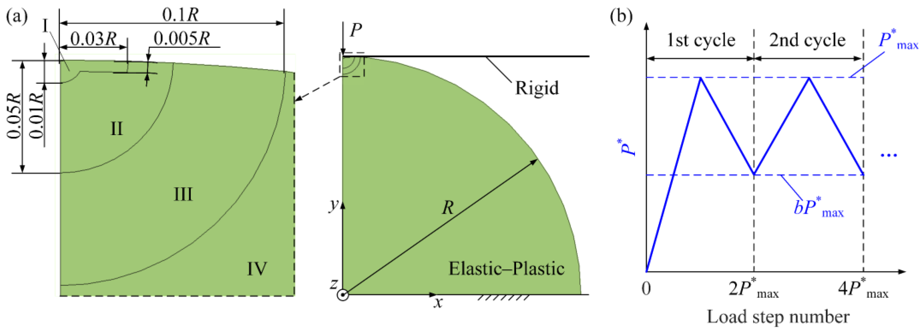
A finite element (FE) model was established to simulate the asperity contact using the commercial software ANSYS 19.2 developed by Ansys, Inc. based in Canonsburg, PA, USA. The 3D asperity was simplified as a 2D axisymmetric model [20,21,22], which was divided into four separate zones. The mesh density decreases as the distance from the sphere summit increases, because high mesh density is necessary near the sphere summit where a high stress/strain gradient exists. The strip in zone I beneath the sphere surface is to guarantee the full coverage of the loaded contact area. Key dimensions of the FE model are illustrated in Figure 2a and the element sizes in zones I–IV are 2 × 10⁻⁴R, 3.2 × 10⁻³R, 0.0125R and 0.05R, respectively. The FE model consists of 18,657 six-node axisymmetric triangular solid elements (PLANE 183) comprising 37,319 nodes, while the rigid flat and sphere surface were modeled by a target element (TARGE 169) and several contact elements (CONTA 172), respectively.
The material was assumed to be isotropic and elastic–perfectly plastic. The elastic and plastic deformation behaviors were governed by Hooke’s and Prandtl–Reuss laws, respectively. These constitutive relationships were settled using the built-in functionality of ANSYS. The transition from elastic to plastic deformation was determined by the von Mises criterion. The material properties of the asperity were Young’s modulus E = 200 GPa, Poisson’s ratio v = 0.32, and yield strength Y = 210 MPa that are typical for low carbon steels. The dimensionless results are independent of R as long as the theory of continuum mechanics holds [23]; therefore, the sphere radius R was set as 10 mm without losing generality. The contact interface was assumed to be frictionless and the encastré boundary condition was applied at the sphere bottom.
Figure 2b shows the cyclic triangular-wave normal loading history applied on the rigid flat. The normal load in the 2nd and subsequent cycles changed from bP*max to P*max, where 0 ≤ b < 1. b = 0 means that the normal load decreased to 0 at the end of each loading–unloading cycle, while other values of b correspond to partial unloading cases. The increment for each load step is 0.5 Pc to ensure convergence. A parameter of 1 ≤ P*max ≤ 700 was selected for investigation to cover a wide enough loading range. A thorough model validation of the FE model is given in Appendix A.

4. Fatemi-Socie Multiaxial Fatigue Criterion

Material points in the asperity undergo multiaxial stress state when the normal load is applied. Moreover, the principal directions constantly change during the loading process. Under this circumstance, the critical plane-based fatigue criteria are most reliable in predicting the position and orientation of fatigue microcracks [24]. The Fatemi-Socie multiaxial fatigue criterion [25] correlates well with both low and high cycle fatigue of materials for gears [26], bearings [27], etc., and is thus adopted in this paper. According to this criterion, the fatigue microcrack at one material point initiates along the critical plane that undergoes the maximum shear strain range over one loading cycle. If there are several critical planes for one material point, the critical plane is defined as the plane where the fatigue damage is the largest, which is quantified by the Fatemi-Socie (FS) damage parameter (it hereafter will be denoted by FSDP for brevity) [25]:
FSDP = Δ γ cp 2 ( 1 + σ cp , max Y )
where Δγcp and σcp,max are the shear strain range and maximum normal stress on the critical plane over one cycle, respectively, and Y is the material yield strength. The initiation life (the number of cycles required for the fatigue microcrack initiation) is a monotone decreasing function of FSDP. As can be seen from Equation (2), a positive σcp,max increases FSDP. This is because a normal tensile stress can reduce the friction between the crack surfaces and accelerate crack generation.

5. Framework of Determining the Critical Plane and FSDP

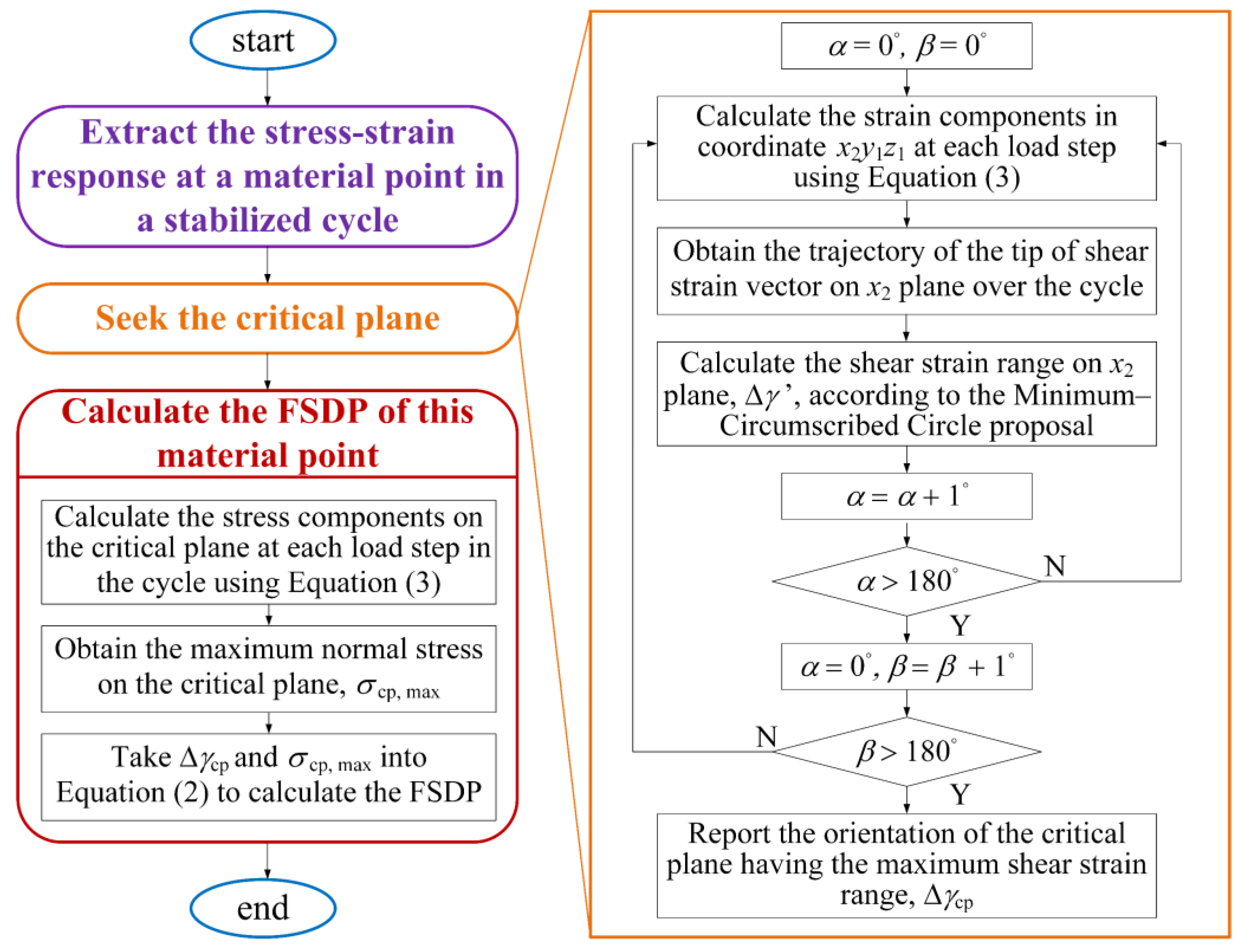
To illustrate the framework of determining the critical plane orientation and FSDP for every material point in the asperity, the numerical procedure in Figure 3 is given and the details are explained as follows.
1.
Extract the stabilized stress–strain response in shakedown state at each material point over one cycle from the FE model (see Section 3 for details);
2.
Seek the critical plane at each material point.
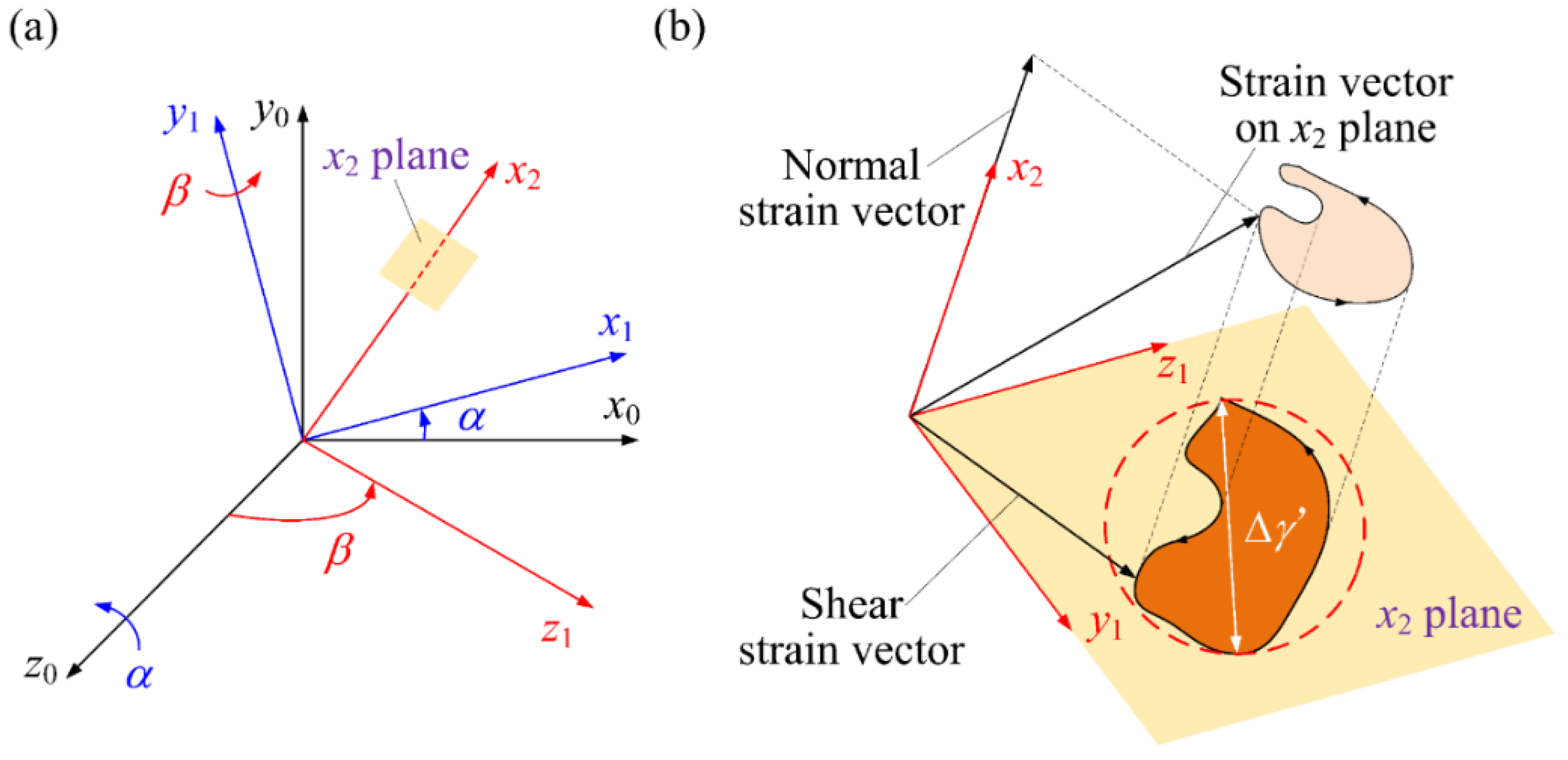
To seek the critical plane of a material point requires examining the shear strain range of all planes passing through this point. The plane to be examined is denoted as the x2 plane in Figure 4a. The orientation of the x2 plane can be described by two Euler angles, α and β. The coordinate x0y0z0 is the original from which the stress–strain response is obtained from the FE model and the origin locates at the material point’s position. α and β denote the rotation angle of coordinate x0y0z0 around z0 axis and the rotation angle of the new coordinate x1y1z0 around y1 axis, respectively. Both α and β change from 0° to 180° with an interval of 1° so that 1812 = 32,761 orientations of the x2 plane are obtained, which are enough to represent arbitrary planes passing through a material point. The strain components in coordinate x2y1z1 (denoted by superscript ’) can be obtained using the following coordinate transformation.
ε = M ε M T , σ = M σ M T
ε = [ ε x x γ x y / 2 0 γ y x / 2 ε y y 0 0 0 ε z z ] , σ = [ σ x x τ x y 0 τ y x σ y y 0 0 0 σ z z ]
M = [ cos β 0 sin β 0 1 0 sin β 0 cos β ] [ cos α sin α 0 sin α cos α 0 0 0 1 ]
where ε and σ are the strain and stress matrices in coordinate x0y0z0, respectively. M is the transformation matrix, and superscript T denotes the transpose operation.
Performing coordinate transformation for the strain matrix of a material point at every load step in a cycle, the trajectory of the tip of shear strain vector (γxy’, γxz’) on x2 plane can be obtained as shown in Figure 4b. As can be seen, this trajectory is usually not a simple straight line due to the non-proportionality of contact loading. To determine the shear strain range, the Minimum-Circumscribed Circle proposal [28,29,30,31] can be used. By searching among the 32,761 orientations of the x2 plane, the critical plane having the maximum Δγ’, i.e., Δγcp, can be found.
3.
Calculate the FSDP at each material point.
The normal stress history on the critical plane in a cycle can be obtained using Equation (3) once the critical plane is settled. Taking the maximum normal stress on the critical plane, σcp,max, and the shear strain range on the critical plane, Δγcp, into Equation (2), FSDP is obtained.

6. Results and Discussion

6.1. Shakedown Analysis

As mentioned in Section 4, it is a premise for using the Fatemi-Socie criterion that the material points enter the shakedown state where the stress–strain responses are stabilized in a cycle. The relationships between various contact parameters in the unloading process are only dependent on the maximum dimensionless load in a cycle, P*max, as mentioned in Section 2; therefore, the shakedown analysis is only executed for complete unloading cases (b = 0) without losing generality. The stress–strain responses up to eight loading cycles were extracted to check whether shakedown was achieved.
Figure 5a shows the increment of equivalent plastic strain Δεpeq in the 1st, 3rd, 5th, and 8th cycles on the surface for P*max = 700. Δεpeq mainly takes place in the 1st cycle, and the increment gradually decreases to zero after a few cycles so that the material points on the sphere surface reach shakedown state. Different decay rates can be observed for Δεpeq. Points at the edge of maximum loaded contact area Amax (x/amax equal or close to 1) spend most cycles reaching the shakedown state among all surface points. The stress–strain response of the surface point at x/amax = 1 is shown in Figure 5b for the first eight cycles. The response gradually becomes linear and reversible in the last few cycles, indicating that all material points enter the shakedown state after eight cycles. Figure 5c,d show the same content as in Figure 5a,b for P*max = 10. In this case, elastic shakedown occurs in the second cycle, much faster than the case of P*max = 700.
A general rule was found that for P*max ranging from 1 to 700, the number of loading cycles required to reach elastic shakedown increased with rising P*max. Therefore, calculation for the stress–strain response in the first eight cycles can ensure that all material points entered the elastic shakedown state, and fatigue analysis was conducted based on the results of the 8th loading cycle thereafter.

6.2. Complete Unloading Cases (b = 0)

Complete loading–unloading widely exists in gears, bearings, and other mechanical components. In addition, it is a special type of cyclic normal loading. Therefore, complete unloading cases are discussed firstly, while the results of partial unloading cases (b ≠ 0) will be illustrated later in Section 6.3.
Using the numerical procedure illustrated in Figure 3, Δγcp and FSDP can be obtained for all material points in the asperity. Figure 6a–c show the contours of Δγcp/(Δγcp)max at the sphere tip for three representative P*max ranging from 1 to 700, where d = Ry denotes the depth from the sphere summit in the axial direction. The area of high Δγcp surrounded by red lines in Figure 6a–c expands in the subsurface as P*max increases. Figure 6d–f show the contours of FSDP/(FSDP)max at the sphere tip under the same loading cases as in Figure 6a–c. A high FSDP area can be observed in the subsurface within 0.5b away from the sphere summit. The maximum FSDP among all the material points, (FSDP)max, occurs near the edge of Amax, where x/amax = 1.
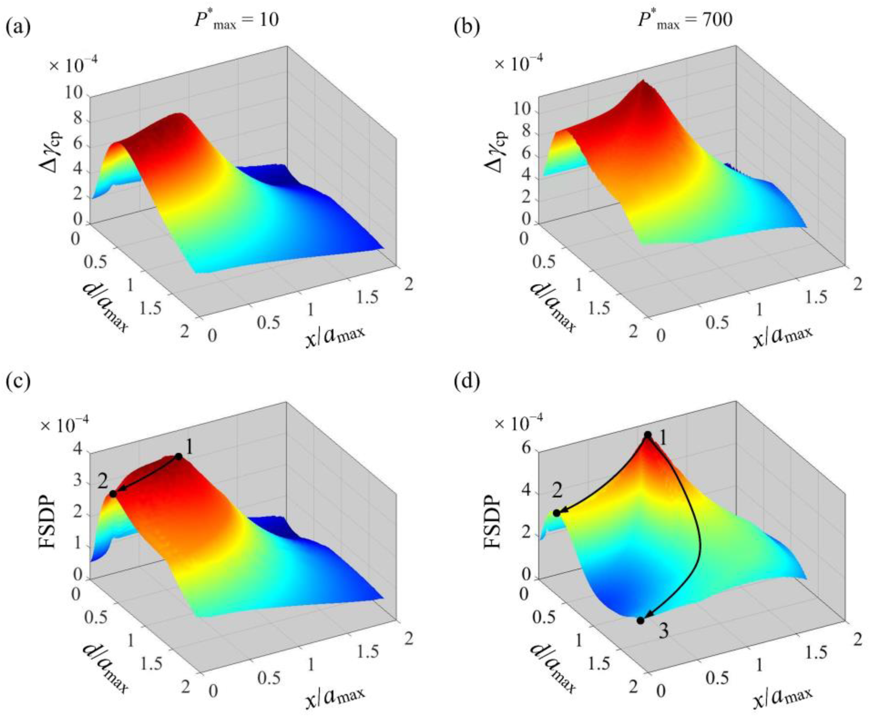
To better illustrate the 2D contours in Figure 6, 3D contours for P*max = 10 and P*max = 700 are shown as examples in Figure 7. For both cases, a ridge-like region in the Δγcp contour (see Figure 7a,b) can be observed that starts from the edge of Amax, extends to the subsurface, and intersects the axis of symmetry at a certain depth from the surface. On the other hand, the FSDP contours for P*max = 10 and P*max = 700 look different, as shown in Figure 7c,d. Although high FSDP occurs in the ridge-like region in the subsurface of the asperity, the number and depth of the ridges varies for the two cases. When P*max = 10, there is only one single ridge in the FSDP contour. When P*max = 700, two ridges exist. The FSDP values for points on these ridges are significantly higher; therefore, fatigue microcracks are much more prone to initiate here.
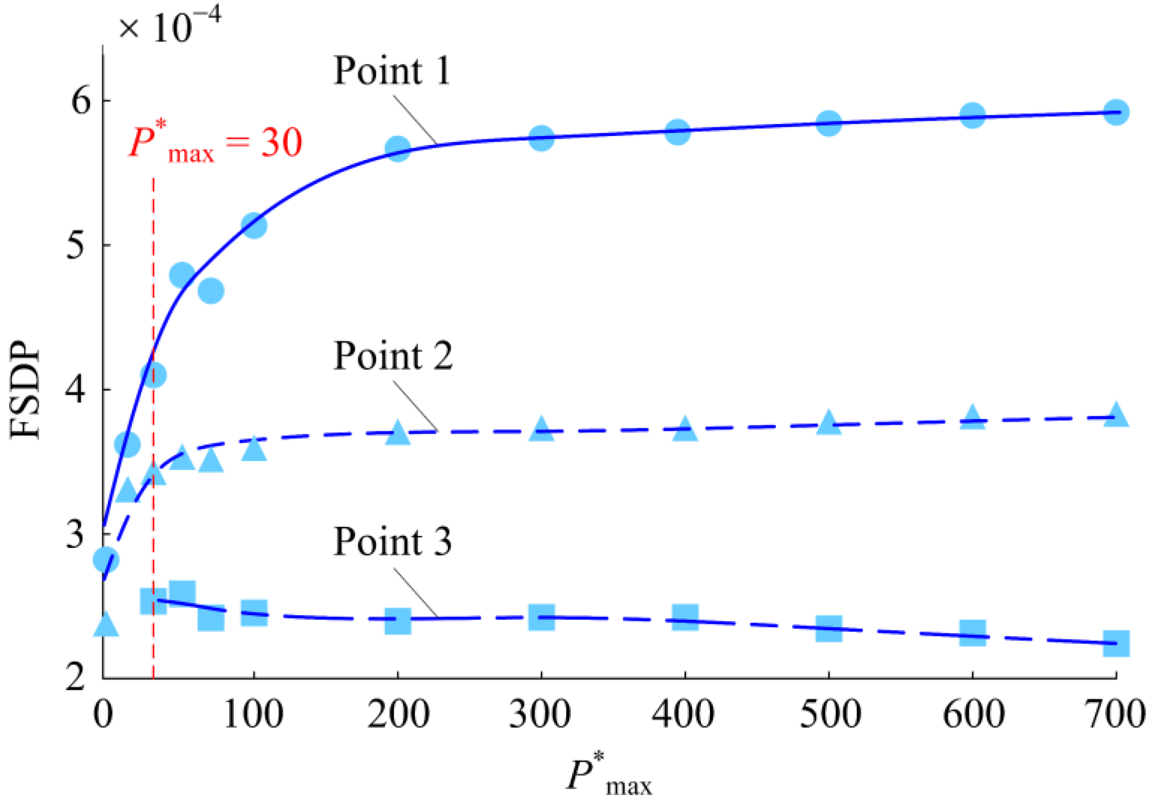
Moreover, the FSDP contours for P*max = 10 and P*max = 700 are representative of two typical FSDP distribution patterns for P*max < 30 and P*max ≥ 30, respectively. Figure 8 shows FSDP at the ridge ends, which are denoted by points 1, 2 and 3 (see Figure 7c,d), as functions of P*max. Point 3 only exists for P*max ≥ 30. Moreover, FSDP at point 3 is significantly lower than that at point 2, as are other points on the lower ridge compared to those on the upper one (see Figure 7d). Hence, for P*max ≥ 30, the upper ridge is much riskier in terms of fatigue microcrack initiation. Thus, the following discussion mainly focuses on the single ridge for P*max < 30 and the upper one for P*max ≥ 30.
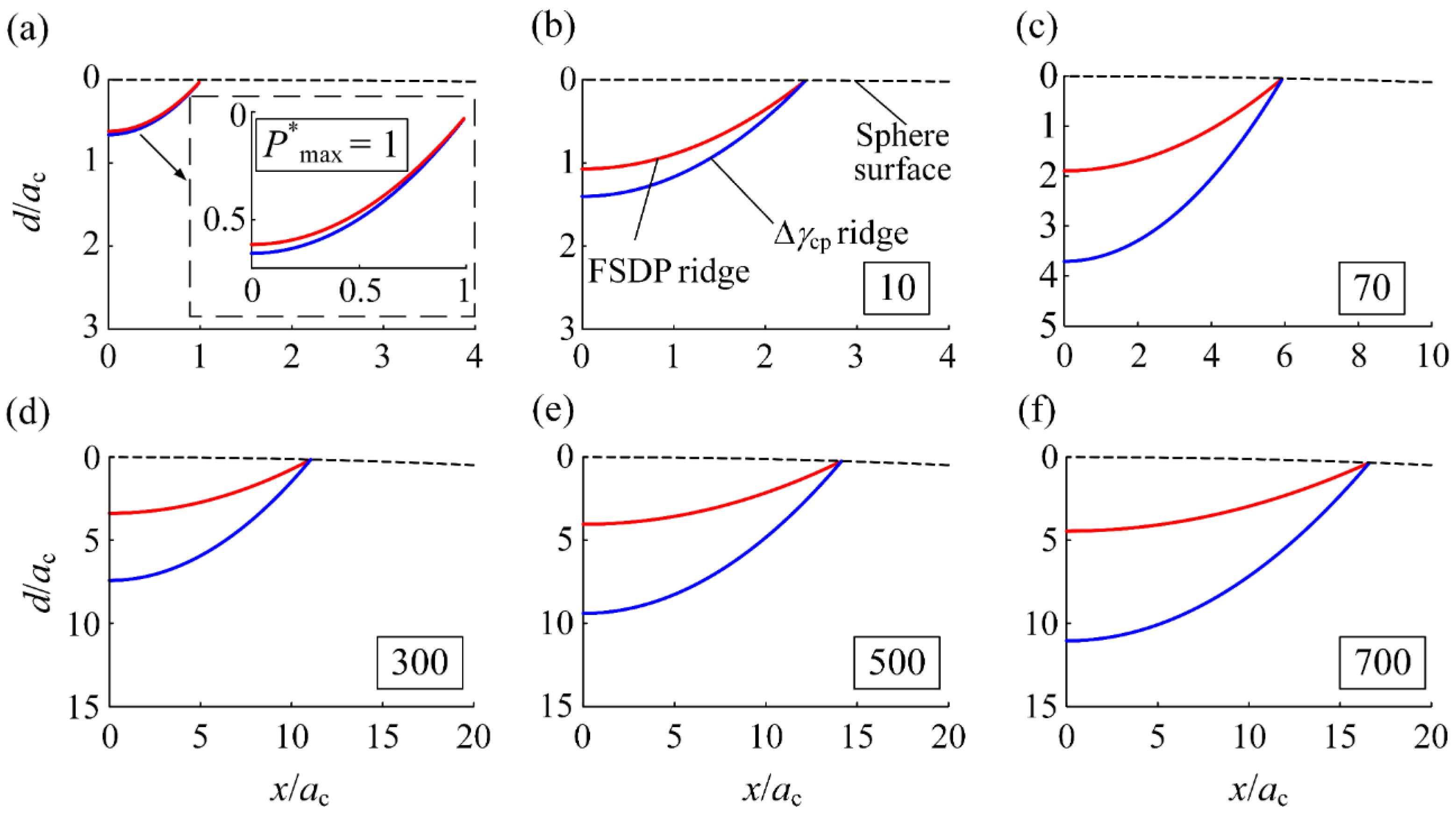
To illustrate the joint effect of the shear strain range and the maximum normal stress on FSDP, the ridge in the Δγcp contour and the (upper) ridge in the FSDP contour are presented in the same picture for 1 ≤ P*max ≤ 700 (see Figure 9). The FSDP ridge is located closer to the surface for the whole load range. With increasing P*max, the gap between the two ridges becomes wider, indicating that the effect of σcp,max is more significant for higher P*max. This makes sense because a higher P*max is associated with stronger compression on the surface. This compression “pushes” the subsurface material away from the sphere tip and results in tensile normal stresses on the critical planes of subsurface points close to the surface. Consequently, the FSDP ridge is located closer to the surface.
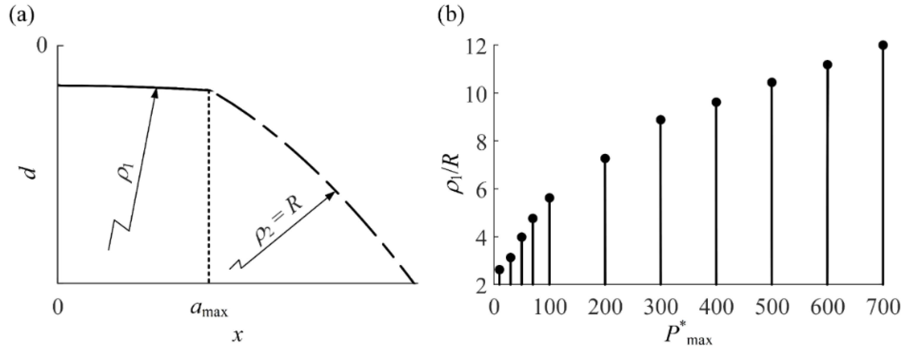
An interesting phenomenon is that both (FSDP)max and (Δγcp)max occur at the edge of Amax, where x/amax = 1 for P*max > 1. To explain this, the residual radius of curvature of the asperity after complete unloading was investigated. As shown in Figure 10a, the portions of the surface within Amax (x/amax ≤ 1) and outside (x/amax > 1) that are represented by solid and dash-dotted curves, respectively, can be fitted by two arcs with different radii of curvature. Figure 10b shows that the increase in ρ1 becomes more salient with increasing P*max. This is because of the residual plastic deformation beneath the loaded contact area. Meanwhile, ρ2/R is equal to 1 for x/amax > 1. In other words, this portion of surface after unloading coincides with the original sphere surface. The difference between ρ1 and ρ2 leads to a sharp change of radius of curvature at the edge of Amax, where x/amax = 1. Therefore, the deformation is concentrated in the region close to the edge of Amax where (FSDP)max occurs.
After undergoing a certain number of loading–unloading cycles, the fatigue microcrack will first initiate at the point with (FSDP)max along its critical plane. As the cycle number further increases, more microcracks will subsequently initiate at points in the descending order of their FSDP. These microcracks will propagate and coalesce to long cracks, as observed in extensive experiments [32,33]. Unfortunately, there does not seem to be a unified theory that can accurately describe the trajectory of both crack initiation and propagation process [27]. It is worth noting that the points on the (upper) ridge in the FSDP contour have much higher FSDP values than those on both sides. Therefore, it is reasonable to assume that the crack is formed along this ridge. This long crack results in a fatigue wear particle detached from the bulk of the asperity. Figure 11a shows the (upper) ridge in the FSDP contour for 1 ≤ P*max ≤ 700. With increasing P*max, the ridge moves deeper into the subsurface, as would be expected. Figure 11b shows the dimensionless volume of the wear particle normalized by the total volume of the asperity under different P*max. The detached volume accounts for no more than 0.1% of the total volume of asperity, indicating that the fatigue wear in an asperity subjected to cyclic normal loading is very mild, even if the normal load is much higher than its critical value Pc.

6.3. Partial Unloading Cases (b ≠ 0)

In most engineering problems, asperities may undergo complex loading histories. Although complete unloading cases where b = 0 have been investigated in detail above, partial unloading cases are more general and need to be investigated.
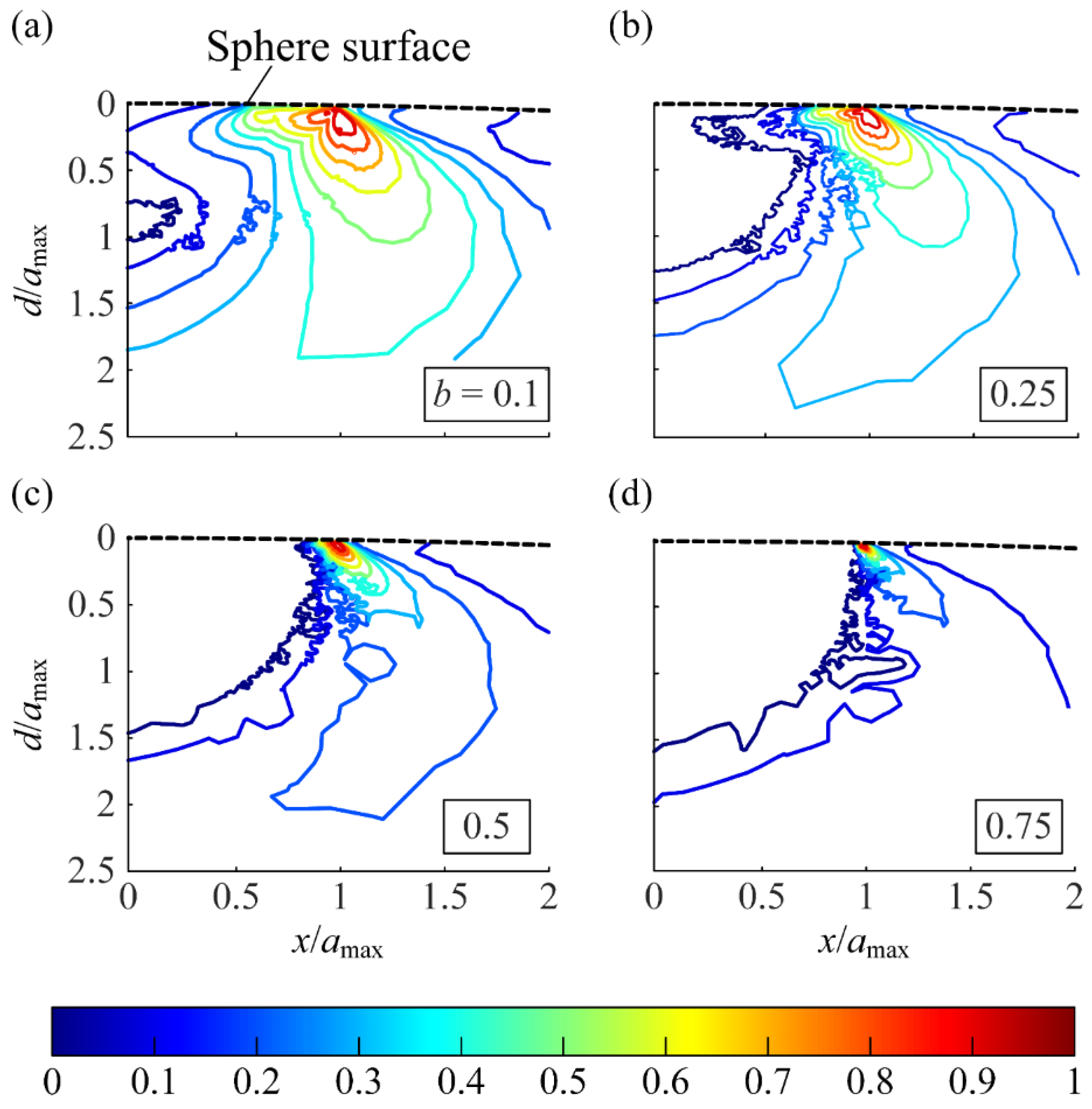
Figure 12a–d show the 2D contours of FSDP when b = 0.1, 0.25, 0.5 and 0.75, respectively for a typical case of P*max = 700. As in the complete unloading cases, (FSDP)max occurs at the edge of Amax. However, the high FSDP area is restricted beneath the edge of Amax, while a low FSDP area occurs in the subsurface within Amax. Higher values of b accompany a larger area with low FSDP. This is because the material points within Amax undergo lower Δγcp than those in the case of b = 0. According to Equation (2), this brings about lower FSDP.
Figure 13 shows the (FSDP)max as functions of P*max under different values of b. The positive correlation between (FSDP)max and P*max is a similarity between partial and complete unloading cases. Meanwhile, the value of b has a dominant effect on (FSDP)max under various values of P*max, ranging from 1 to 700. Higher values of b not only restrict the high FSDP area, but also decrease (FSDP)max.
Further work can be done to supplement and improve the present work. Firstly, because deviations from reality are inevitable due to friction and time-varying temperature, experiments are strongly recommended as the solid validation of the theoretical analysis results. Other complex loading histories can be applied in addition to triangular-wave normal loadings. The constitution law of the material should be carefully selected to better simulate the practical surface wear. Moreover, the fatigue crack propagation can be investigated to predict the volume of fatigue wear particle accurately. Finally, the relationship between the fatigue in a single asperity with the overall fatigue damage of a rough surface remains to be studied.

7. Conclusions

In this study, the fatigue damage of a frictionless asperity subjected to cyclic normal loading was evaluated using the multiaxial Fatemi-Socie fatigue criterion. The shakedown analysis based on an elastic–plastic FE model showed that all material points in the asperity entered the elastic shakedown state after a few loading cycles. The cyclic loading applied to the asperity can be divided into two categories, i.e., the asperity is completely unloaded and partially unloaded in a loading cycle. For the case of complete unloading, ridge-like regions were observed from both the Δγcp and FSDP contours at the sphere tip. The maximum fatigue damage, (FSDP)max occurred at the edge of the maximum contact area Amax. This resulted from the sharp change of radius of curvature at the edge of Amax after unloading. Two typical patterns for FSDP contours were found for P*max < 30 and P*max ≥ 30. Fatigue microcracks were prone to occurring along the single ridge in the FSDP contour for P*max < 30 and the upper one for P*max ≥ 30. The (upper) ridge in the FSDP contour was assumed as the long crack that eventually resulted in a wear particle detaching from the asperity. The wear particle only occupied a tiny portion of the whole asperity, indicating that contact fatigue wear is very mild. For the case of partial unloading, the region of high FSDP was only restricted below the edge of Amax. Moreover, the ridge-like regions of high FSDP were not observed in this case, and higher values of b led to lower (FSDP)max, as would be expected. Finally, directions of future work have been suggested.

Author Contributions

Conceptualization, Z.C.; funding acquisition, Z.T. and S.T.; investigation, Y.J.; methodology, Z.C. and Y.J.; software, Z.C. and Y.J.; supervision, Z.T. and S.T.; validation, Y.J.; visualization, Y.J.; writing—original draft preparation, Z.C.; writing—review and editing, Y.J. and Z.T. All authors have read and agreed to the published version of the manuscript.

Funding

This research was funded by the National Key R&D Program of China (2019YFB2004604), the National Natural Science Foundation of China (52075481), the Zhejiang Provincial Natural Science Foundation of China (LR19E050002), the Key R&D Program of Zhejiang Province (2020C01152), and the “Innovation 2025” Major Project of Ningbo (2020Z110).

Institutional Review Board Statement

Not applicable.

Informed Consent Statement

Not applicable.

Data Availability Statement

The data presented in this study are available on request from the corresponding author.

Conflicts of Interest

The authors declare no conflict of interest.

Nomenclature

Acontact area
acontact radius
ddepth measured from the sphere summit
EYoung’s modulus
Pcontact load
Rradius of the spherical asperity
Yyield strength
FSDPFatemi-Socie damage parameter
critical planethe plane that has the maximum shear strain range over a cycle
α, βEuler angle that describes the orientation of a plane
εpeqequivalent plastic strain
Δγshear strain range on a plane over a cycle
Δγcpshear strain range on the critical plane over a cycle
vPoisson’s ratio
σcp,maxmaximum normal stress on the critical plane over a cycle
ωinterference
Subscripts:
ccritical values of contact parameters at elasticity terminus
cpcritical plane
maxmaximum value over a cycle
Superscripts:
maxmaximum value among all the material points
*dimensionless contact parameters normalized by corresponding critical values
entities after coordinate transformation

Appendix A

Based on the assumption that the asperity material is purely elastic, the obtained stress components can be compared with those from the Hertz solution [34]. Comparison was made only for nodes in zones I and II (see Figure 4a) at five representative values of P*max ranging from 1 to 700. The maximum errors are listed in Table A1, where σzx and σzy are not shown because they are zero due to the axisymmetry.
However, the plasticity of the real material should be taken into account. Unfortunately, no analytic solution for the stress/strain field in the plastic stage is available. Thus, P* vs. ω, A* vs. ω* in the first loading–unloading cycle was compared with empirical formulas for the loading [19] and unloading processes [8]. The R2 goodness-of-fit values of these empirical formulas fitting P* vs. ω* and A* vs. ω* that were obtained from the FE model are listed in Table A2. Finally, the robustness of the FE model was proven by a mesh convergence test. The difference between the maximum FSDP obtained from the meshes of element size that were iteratively reduced by 50% and the original mesh is shown in Table A3. The results in Table A1, Table A2 and Table A3 can guarantee the accuracy of the FE model.
Table A1. The maximum errors of stress components obtained from the elastic FE model.
P*maxMaximum Errors (%)
σxσyσzσxy
101.850.638.030.73
502.640.654.540.81
1002.90.643.220.78
3002.640.342.741.07
7002.760.342.820.58
Table A2. The R2 goodness-of-fit of the empirical formulas for the loading and unloading process fitting P* vs. ω* and A* vs. ω* obtained from the elastic–plastic FE model.
P*maxR2 Goodness-of-Fit for the Loading ProcessR2 Goodness-of-Fit for the Unloading Process
A* vs. ω *P* vs. ω * A* vs. ω *P* vs. ω *
100.9780.9310.9320.972
500.9700.9700.9460.961
1000.9590.9820.9520.955
3000.9300.9720.9570.954
7000.9360.9420.9430.974
Table A3. The difference between the maximum FSDP obtained from the meshes of iteratively decreasing mesh size and the original mesh.
P*maxDifference in the Maximum FSDP (%)
1st Iteration2nd Iteration
104.9665.215
500.8811.116
1000.0522.695
3001.0393.999
7001.191.607

References

  1. Manam, N.S.; Harun, W.S.W.; Shri, D.N.A.; Ghani, S.A.C.; Kurniawan, T.; Ismail, M.H.; Ibrahim, M.H.I. Study of corrosion in biocompatible metals for implants: A review. J. Alloys Compd. 2017, 701, 698–715. [Google Scholar] [CrossRef] [Green Version]
  2. Nečas, D.; Usami, H.; Niimi, T.; Sawae, Y.; Křupka, I.; Hartl, M. Running-in friction of hip joint replacements can be significantly reduced: The effect of surface-textured acetabular cup. Friction 2020, 8, 1137–1152. [Google Scholar] [CrossRef] [Green Version]
  3. Tang, Z.; Zhou, D.; Jia, T.; Pan, D.; Zhang, C. Investigation of lubricant transfer and distribution at head/disk interface in air-helium gas mixtures. Friction 2019, 7, 564–571. [Google Scholar] [CrossRef] [Green Version]
  4. Cao, W.; Ren, S.; Pu, W.; Xiao, K. Microstress cycle and contact fatigue of spiral bevel gears by rolling-sliding of asperity contact. Friction 2020, 8, 1083–1101. [Google Scholar] [CrossRef] [Green Version]
  5. Hu, S.; Huang, W.; Brunetiere, N.; Liu, X.; Wang, Y. Truncated separation method for characterizing and reconstructing bi-Gaussian stratified surfaces. Friction 2017, 5, 32–44. [Google Scholar] [CrossRef] [Green Version]
  6. Patil, D.B.; Eriten, M. Frictional energy dissipation in spherical contacts under presliding: Effect of elastic mismatch, plasticity and phase difference in loading. ASME J. Appl. Mech. 2015, 82, 011005. [Google Scholar] [CrossRef]
  7. Jackson, R.; Chusoipin, I.; Green, I. A finite element study of the residual stress and deformation in hemispherical contacts. ASME J. Tribol. 2005, 127, 484–493. [Google Scholar] [CrossRef] [Green Version]
  8. Etsion, I.; Kligerman, Y.; Kadin, Y. Unloading of an elastic-plastic loaded spherical contact. Int. J. Solids Struct. 2005, 42, 3716–3729. [Google Scholar] [CrossRef]
  9. Zhao, J.H.; Nagao, S.; Zhang, Z.L. Loading and unloading of a spherical contact: From elastic to elasticperfectly plastic materials. Int. J. Mech. Sci. 2012, 56, 70–76. [Google Scholar] [CrossRef]
  10. Zhao, B.; Zhang, S.; Wang, Q.F.; Zhang, Q.; Wang, P. Loading and unloading of a power-law hardening spherical contact under stick contact condition. Int. J. Mech. Sci. 2015, 94–95, 20–26. [Google Scholar] [CrossRef]
  11. Jana, T.; Mitra, A.; Sahoo, P. Unloading analysis of elastically and plastically graded hemispherical contact with rigid flat. Tribol. Int. 2020, 142, 105973. [Google Scholar] [CrossRef]
  12. Kadin, Y.; Kligerman, Y.; Etsion, I. Multiple loading-unloading of an elastic-plastic spherical contact. Int. J. Solids Struct. 2006, 43, 7119–7127. [Google Scholar] [CrossRef] [Green Version]
  13. Zait, Y.; Zolotarevsky, V.; Kligerman, Y.; Etsion, I. Multiple normal loading-unloading cycles of a spherical contact under stick contact condition. ASME J. Tribol. 2010, 132, 041401. [Google Scholar] [CrossRef]
  14. Wang, J.; Li, Q.; Yang, C.; Zhou, C. Repeated loading model for elastic–plastic contact of geomaterial. Adv. Mech. Eng. 2018, 10, 1–15. [Google Scholar] [CrossRef]
  15. Xu, H.; Komvopoulos, K. Fracture mechanics analysis of asperity cracking due to adhesive normal contact. Int. J. Fract. 2013, 181, 273–283. [Google Scholar] [CrossRef]
  16. Xu, H.; Komvopoulos, K. A fracture mechanics analysis of asperity cracking due to sliding contact. Int. J. Solids Struct. 2019, 171, 1–9. [Google Scholar] [CrossRef]
  17. Zhao, B.; Shen, F.; Cui, Y.; Xie, Y.; Zhou, K. Damage analysis for an elastic-plastic body in cylindrical contact with a rigid plane. Tribol. Int. 2017, 115, 18–27. [Google Scholar] [CrossRef]
  18. Green, I. Poisson ratio effects and critical values in spherical and cylindrical hertzian contacts. Int. J. Appl. Mech. Eng. 2005, 10, 451–462. [Google Scholar]
  19. Jackson, R.L.; Green, I. A finite element study of elasto-plastic hemispherical contact against a rigid flat. J. Tribol. 2005, 127, 343–354. [Google Scholar] [CrossRef] [Green Version]
  20. Chen, Z.; Goltsberg, R.; Etsion, I. A universal model for a frictionless elastic-plastic coated spherical normal contact with moderate to large coating thicknesses. Tribol. Int. 2017, 114, 485–493. [Google Scholar] [CrossRef]
  21. Chen, Z.; Jiang, Y.; Tong, Z.; Tong, S.; Tan, J. Fatigue analysis of spherical contact subjected to cyclic elastic-plastic normal loading. J. Tribol. 2021, 1–20. [Google Scholar] [CrossRef]
  22. Tong, Z.; Xin, J.; Tong, S.; Yang, Z.; Zhao, J.; Mao, J. Internal flow structure, fault detection, and performance optimization of centrifugal pumps. J. Zhejiang Univ. A 2020, 21, 85–117. [Google Scholar] [CrossRef]
  23. Zhao, B.; Xu, H.; Lu, X.; Ma, X.; Shi, X.; Dong, Q. Contact behaviors of a power-law hardening elastic–plastic asperity with soft coating flattened by a rigid flat. Int. J. Mech. Sci. 2019, 152, 400–410. [Google Scholar] [CrossRef]
  24. Fatemi, A.; Shamsaei, N. Multiaxial fatigue: An overview and some approximation models for life estimation. Int. J. Fatigue 2011, 33, 948–958. [Google Scholar] [CrossRef]
  25. Fatemi, A.; Socie, D.F. A critical plane approach to multiaxial fatigue damage including out-of-phase loading. Fatigue Fract. Eng. Mater. Struct. 1988, 11, 149–165. [Google Scholar] [CrossRef]
  26. Wang, W.; Liu, H.; Zhu, C.; Du, X.; Tang, J. Effect of the residual stress on contact fatigue of a wind turbine carburized gear with multiaxial fatigue criteria. Int. J. Mech. Sci. 2019, 151, 263–273. [Google Scholar] [CrossRef]
  27. Vijay, A.; Sadeghi, F. A continuum damage mechanics framework for modeling the effect of crystalline anisotropy on rolling contact fatigue. Tribol. Int. 2019, 140, 105845. [Google Scholar] [CrossRef]
  28. Papadopoulos, I.V. Critical plane approaches in high-cycle fatigue: On the definition of the amplitude and mean value of the shear stress acting on the critical plane. Fatigue Fract. Eng. Mater. Struct. 1998, 21, 269–285. [Google Scholar] [CrossRef]
  29. Liu, Z.; Tsang, K.S.; Liu, Y.; Pang, J.H.L. Finite element and experimental study on multiaxial fatigue analysis of rail clip failures. Fatigue Fract. Eng. Mater. Struct. 2020, 43, 2390–2401. [Google Scholar] [CrossRef]
  30. Tong, Z.; Cheng, Z.; Tong, S. A review on the development of compressed air energy storage in China: Technical and economic challenges to commercialization. Renew. Sustain. Energy Rev. 2021, 135, 110178. [Google Scholar] [CrossRef]
  31. Chen, Y.; Tong, Z.; Zheng, Y.; Samuelson, H.; Norford, L. Transfer learning with deep neural networks for model predictive control of HVAC and natural ventilation in smart buildings. J. Clean. Prod. 2020, 254, 119866. [Google Scholar] [CrossRef]
  32. Socie, D.F.; Marquis, G.B. Multiaxial Fatigue; Society of Automotive Engineers: Warrendale, PA, USA, 2000. [Google Scholar]
  33. Matecka, J.; Rozumek, D. Metallographic and Mechanical Research of the O–Ti2AlNb Alloy. Materials 2020, 13, 3006. [Google Scholar] [CrossRef]
  34. Fischer-Cripps, A.C. Introduction of Contact Mechanics, 2nd ed.; Springer: Sydney, NSW, Australia, 2007; ISBN 9780387681870. [Google Scholar]
Figure 1. (a) Various examples of surface fatigue wear, and (b) the spherical contact model for one single asperity.
Metals 11 00545 g001
Figure 2. (a) Details of the finite element FE model and (b) the normal contact loading history.
Metals 11 00545 g002
Figure 3. The numerical procedure to determine the critical plane and Fatemi–Socie damage parameter (FSDP) of a material point.
Metals 11 00545 g003
Figure 4. (a) Geometrical definition of Euler angles and (b) the Minimum-Circumscribed Circle proposal [28,29].
Metals 11 00545 g004
Figure 5. (a) Δεpeq on the sphere surface after unloading, and (b) shear stress–strain response of the point at the edge of Amax in eight loading cycles, where P*max = 700. (c,d) The same content as in (a,b), where P*max = 10.
Metals 11 00545 g005
Figure 6. The contour of (a) Δγcp/(Δγcp)max and (d) FSDP/(FSDP)max at the sphere tip for P*max = 10. (b,e) The same content as in (a,d), where P*max = 70. (c,f) The same content as in (a,d), where P*max = 700.
Metals 11 00545 g006
Figure 7. Examples for the typical patterns of Δγcp contour and FSDP contour for P*max < 30 and P*max ≥ 30, where (a,c) P*max = 10 and (b,d) P*max = 700.
Metals 11 00545 g007
Figure 8. FSDP of the points at the ridge ends as functions of P*max.
Metals 11 00545 g008
Figure 9. The ridge in the Δγcp contour and the (upper) ridge in the FSDP contour for P*max = (a) 1, (b) 10, (c) 70, (d) 300, (e) 500 and (f) 700.
Metals 11 00545 g009
Figure 10. (a) An example of deformed sphere surface after unloading and (b) the dimensionless residual radius of curvature of the sphere surface within Amax after unloading for different P*max.
Metals 11 00545 g010
Figure 11. (a) The (upper) ridge in FSDP contours for 1 ≤ P*max ≤ 700, and (b) the dimensionless volume of the wear particle, V/(2/3πR2), under different P*max.
Metals 11 00545 g011
Figure 12. The contour of FSDP/(FSDP)max at the sphere tip when P*max = 700 for b = (a) 0.1, (b) 0.25, (c) 0.5 and (d) 0.75.
Metals 11 00545 g012
Figure 13. The effect of b on (FSDP)max for 1 ≤ P*max ≤ 700.
Metals 11 00545 g013
Publisher’s Note: MDPI stays neutral with regard to jurisdictional claims in published maps and institutional affiliations.