Article

Production and Properties of High Entropy Carbide Based Hardmetals

1
Fraunhofer IKTS, Fraunhofer Institute for Ceramic Technologies and Systems, 01277 Dresden, Germany
2
Institute of Materials Science (IfWW), Technische Universität Dresden, 01067 Dresden, Germany
*
Author to whom correspondence should be addressed.
Metals 2021, 11(2), 271; https://doi.org/10.3390/met11020271
Submission received: 18 December 2020 / Revised: 28 January 2021 / Accepted: 2 February 2021 / Published: 5 February 2021
(This article belongs to the Special Issue High Entropy Materials: Challenges and Prospects)

Abstract

:
Dense, high-entropy carbide cobalt-bonded hardmetals with two different compositions, namely (Hf-Ta-Ti-Nb-V)C-19.2 vol% Co and (Ta-Ti-Nb-V-W)C-19.2 vol% Co, were successfully manufactured by gas pressure sintering (SinterHIP) at 1400 °C and 100 bar Ar pressure. The microstructure of these hardmetals consists of a rigid skeletal carbide phase embedded in a tough Co binder phase. EDS mappings showed that the high-entropy carbide phase did not decompose and that a typical hardmetal microstructure was realized. Only in the case of the (Hf-Ta-Ti-Nb-V)C-Co hardmetal was some undissolved TaC and HfO2, as well as some clustered vanadium titanium carbide phase, found, resulting in a split-up of the HEC phase into two very similar HEC phases. This resulted in a reduced hardness to fracture toughness ratio for this composition. Measurements of magnetic saturation polarization showed values between 57.5% and 70% of theoretical magnetic saturation polarization, indicating marginal dissolution of the carbide-forming metal elements in the binder phase. The hardness value HV10 for (Hf-Ta-Ti-Nb-V)C-19.2 vol% Co was 1203 HV10 and 1432 HV10 for (Ta-Ti-Nb-V-W)C-19.2 vol% Co.

1. Introduction

Basic hardmetals (also known as cemented carbides) and cermets consist of hard carbide phases (WC or TiCN) mixed with a ductile binder phase (Co/Ni/Fe). Extensive studies on monocarbide hardmetal compositions such as WC-Co, WC-Ni, NbC-Co, NbC-Ni, VC-Ni, Cr3C2-Ni, etc., exist in the literature [1,2,3,4,5,6]. Other carbides such as TiC, TaC, and NbC are also present as a mixed carbide composition, such as (Ti, Ta, Nb, W)C, for better wear resistance, hardness, and toughness [7]. Studies on mixed carbides such as WC-Cr3C2-Co, WC-VC-Co, (Ta, Mo)C-Co/Ni, (Ta, W)C-Co/Ni [8,9,10,11,12,13] showed that the stability of these mixed carbides strongly depends on their chemical composition and solubility in the metal binder phase.
Furthermore, several cermet compositions such as (Ti-Mo)C-Co, (Ti, Mo, W)C-Co, (W-Ti)C-(Co/Ni), TiN-Ni, TiC-Mo-Ni, WC-(Ta, Nb)C, TiC-Mo2C-(TaC-NbC-VC)Ni, and (Ti, W, Ta)C-Mo-Ni have been studied [14,15,16,17,18,19,20,21]. In cermets too, the addition of additional carbides to its TiC/TiCN-based main hard phase is mostly carried out only in small amounts for the improvement of wettability, the suppression of grain growth, and the enhancement of toughness [7]. Regardless of the composition, cermets mainly consist of a multi-phase core–rim structure with unalloyed lighter TiCN in the core surrounded by other heavier carbides in the rim [22].
Replacing traditional binders (Co/Ni/Fe or mixtures thereof) with high-entropy alloys (HEA) show a good wettability of WC, high toughness, prominent wear resistance, and high temperature stability. For example, by replacing Co with CoCrFeNi, CoCrFeMnNi or CoCrFeNiV binder, the plastic deformation resistance of hardmetals was enhanced, outperforming traditional WC-Co hardmetals [23,24]. In cermets too, CoCrFeNiCu can lead to less interfaces by inhibiting core–rim structure and grain growth, thus enhancing wettability, hardness, and toughness [23].
Inspired by the concept of HEA, high entropy carbides (HEC) have gained attention in recent years. As opposed to having a principal metal carbide with minor additions of other carbides, HEC´s are composed of five or more equiatomic carbides. Several researchers have already studied a broad range of medium- and high-entropy carbide compositions, such as (Hf-Zr-Ta-Nb-Ti)C, (Hf-Ta-Zr-Nb)C, (Ti-Zr-Hf-V-Nb)C or (Hf-Zr-Ti-Ta-Nb)C [21,25,26,27,28,29,30,31,32]. These HEC´s can form a single-phase solid solution by increasing the solubility among elements due to enhanced mixing entropy, and suppress the formation of intermetallic phases and element segregations.
Spark plasma sintering (SPS), also known as field-assisted sintering (FAST), is the most used method for the production of bulk HEC so far [26,27,29,30,32]. Several HEC compositions have also been manufactured by hot pressing [31,33,34] and vacuum sintering [34]. Furthermore, the synthesis of HEC powders has been studied for several compositions [35,36]. These studies have shown that HEC possesses superior hardness, toughness, and wear resistance as compared to certain monocarbides. The knowledge of the production and properties of HEC has opened up new possibilities for tailoring a wide range of high-entropy carbide-based hardmetals. However, the properties of this newly emerging class of materials, e.g., hardmetal compositions such as HEC-Co, HEC-Ni and similar, remain so far unexplored [37].
In this study, two different pre-manufactured HEC compositions were crushed to HEC powders and mixed with Co, followed by subsequent sintering using a SinterHIP process. The influence of HEC compositions on the density, grain size, and basic mechanical properties of the obtained HEC-Co hardmetals was studied and is discussed within this work for the first time.

2. Materials and Methods

2.1. Preparation of HEC Powders

High-entropy carbides of two different compositions were manufactured using a conventional powder metallurgical route. Commercially available refractory carbides of HfC, TaC, TiC, NbC, VC, and WC were mixed in equiatomic proportions to produce two different high-entropy carbides: (Hf-Ta-Ti-Nb-V)C and (Ta-Ti-Nb-V-W)C. Their exact compositions are given in Table 1. The details on powder supplier, FSSS particle size, specific surface area (BET), dBET particle size, as well as the oxygen content of the powders, are given in Table 2.
The specific surface (SBET) was measured under Krypton (ASAP 2020 MP, Micromeritics, Norcross, GA, USA), and the particle diameter dBET was calculated using the formula dBET = 6000/(SBET * density). The mean particle size dFSSS was measured with a Fisher Sub sieve sizer (Model 95, Fisher Scientific, Waltham, MA, USA).
Refractory carbide powders were mixed in compositions given in Table 1, ball-milled in n-heptane, vacuum dried, and sieve granulated. The granulated powder mixtures were uniaxially pressed to bars and sintered by gas pressure sintering (FPW 280/600, FCT, Sonneberg, Germany). The gas pressure sintering cycle, here referred to as sinterHIP, was carried out at 1950 °C with a holding time of 240 min in vacuum, followed by 45 min of 100 bar Ar pressure. The two prepared HEC 1 and HEC 2 compositions (Table 1) were again crushed in a vibratory disc mill (RS 200, Retsch, Haan, Germany, WC-Co vial and disc) at 700 RPM, and sieved to a particle size of less than 20 µm.

2.2. Preparation of HEC-Co Hardmetals

The crushed HEC 1 and HEC 2 powders were mixed with Co (Umicore, half micron, dFSSS = 0.7 µm, O2 content = 0.69 wt. %) to a Co content of 19.2 vol% (equivalent binder content of a WC-12 wt. % Co hardmetal), and ball-milled for 48 h. This was followed by vacuum drying and sieve granulation. The granulated powder mixture was then uniaxially pressed to bending bars and sintered. The sinterHIP cycle was caried out at 1400 °C and an Ar pressure of 100 bar with a holding time of 45 min. Altogether, two different HEC-based hardmetals (HEC-Co) were produced: composition (Hf-Ta-Ti-Nb-V)C-Co is designated as HEC 1-Co and composition (Ta-Ti-Nb-V-W)C-Co as HEC 2-Co.
The density of all sintered samples was measured according to ISO 3369. For microstructural analysis, dense samples were ground and polished down to 1 µm using different diamond slurries, similar to what is described in ISO 4499-1. Images of microstructures were taken using the field emission scanning electron microscope (FESEM) ULTRA 55 (Carl Zeiss Microscopy, Oberkochen, Germany), which was also used to perform EDS analysis. ISO porosity was determined according to ISO 4499-4. The phase composition of the powder mixtures (as pressed) as well as of sintered samples was analyzed by X-ray diffraction (XRD) using a diffractometer D8 Advance (Bruker AXS, Karlsruhe, Germany), operated with Cu-Kα radiation with a LynxEye position-sensitive detector (PSD, Bruker AXS, Karlsruhe, Germany) and a nickel filter located in the primary beam. The Diffrac.EVA program and the JCPDS database (2020) were used for phase analysis. The magnetic properties coercivity Hc and magnetic saturation polarization mS were measured according to ISO 3326.
The Vickers hardness (HV10) of sintered samples was measured in agreement with ISO 3878 with a load of 10 kP and five measurements per sample. Fracture toughness (K1C) was calculated by measuring the Vickers indentation crack length using the Shetty equation [38].

3. Results and Discussion

3.1. Synthesis of HEC Powders

The HEC powders were synthesized similar to bulk binderless HEC ceramics [39], but with slightly adjusted synthesis conditions. Figure 1a,b show the corresponding micrographs of the bulk HEC compositions HEC 1 ((Hf-Ta-Nb-Ti-V)C) and HEC 2 ((Ta-Nb-Ti-V-W)C) which were used for the HEC powder preparation.
From Figure 1, differences in grain size can be observed. The grain sizes of HEC 1 can be estimated to be in the range of approx. 2 µm to 5 µm, while for HEC 2, it ranges from approx. 5 µm to 30 µm. After crushing the HEC powders to <20 µm, it is expected that in the case of HEC 1 some polycrystalline HEC grains remain, while in the case of HEC 2 mostly monocrystalline HEC grains will be present.
For HEC 1, the EDS measurements showed small third phases next to the HEC phase consisting of either TaC or HfO2. In the case of HEC 2, only the HEC phase and small amounts of free carbon (black spots in Figure 1b) were detected. Nevertheless, semiquantitative EDS measurement and the XRD measurement (see next section) showed that the amount is too small to change the composition of the HEC significantly.

3.2. Properties of HEC-Co Hardmetals

The prepared HEC 1 and HEC 2 powders were used as a hard phase, which were then mixed with 19.2 vol% Co (equivalent to WC-12 wt. % Co). First, the samples subjected to sinterHIP were characterized by measuring density. Theoretical density, calculated according to the rule of mixture, Archimedes density, and relative density are given in Table 3.
The data in Table 3 prove that the samples are completely densified. The 101% theoretical density for HEC 2-Co is due to the inaccuracy of the calculation of theoretical density. The SEM micrographs of the polished cross section reveal that the samples are completely densified with an ISO porosity of A02B00C00 for both compositions.
The backscattered electron micrographs of both HEC-Co hardmetals in Figure 2 represent various phases. The dark gray represents the Co binder phase, whereas gray and light gray contrasts show the carbide grains. Both micrographs represent a skeletal microstructure of cubic carbides embedded in a cobalt binder phase. Differences in grain size directly correspond to the initial grain sizes of the HEC materials used as starting materials (see Figure 1).
Light gray spots could be observed at the grain boundaries of HEC 1-Co (Figure 2a). These could be carbide precipitations with a different composition. There are no light gray spots (as opposed to light gray phases) observed in HEC 2-Co (Figure 2b).
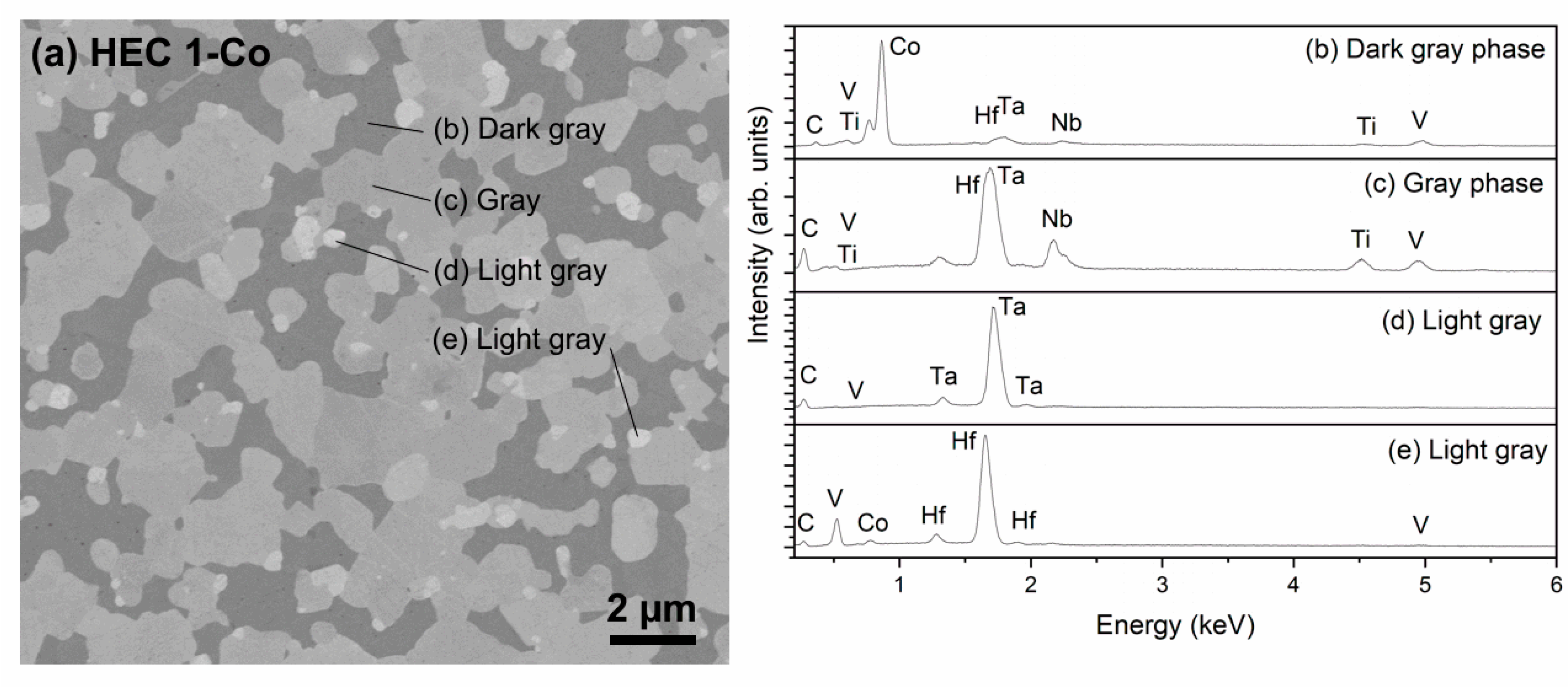
Figure 3 shows the SEM image of HEC 1-Co, the composition of which was (Hf-Ta-Ti-Nb-V)C with Co binder, and the corresponding EDS results. There are different gray levels shown in the electron micrographs. The respective element peaks in Figure 3b–d show that the dark gray phase is the cobalt binder with a low amount of dissolved carbide-forming metals (Hf, Ta, Nb, V and Ti), the gray phase is the complex solid solution of (Hf-Ta-Nb-Ti-V)C, and the light gray phase contains either Ta or Hf as the main component.
In most parts, the cubic carbides are all mixed together forming the hard phase, which is surrounded by Co (dark gray phase). The light gray round grains, which are rich in Hf and Ta, seem to be the remains of undissolved or just partially dissolved TaC and HfC from its corresponding HEC 1 powder.
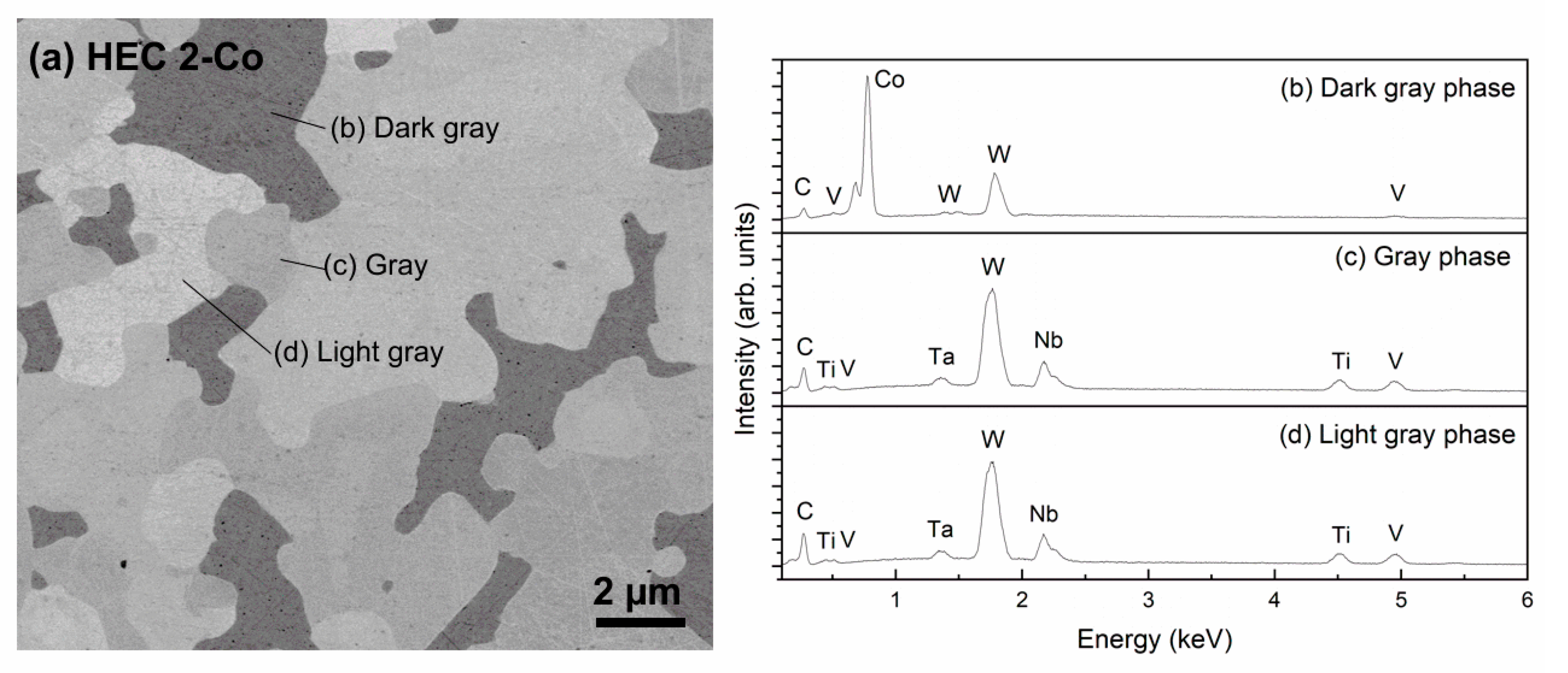
The SEM images of HEC 2-Co (Figure 4a) show three kinds of phases: dark gray, gray, and light gray. EDS spectra of HEC 2-Co (Figure 4b–d) reveal that the dark gray phase is rich in Co and poor in other carbide-forming metals (Ta, Ti, Nb, V, W). The gray phase and light gray phase represent the high-entropy carbide grains, both rich in W. In this case, only an orientational contrast is responsible for the different gray shades.
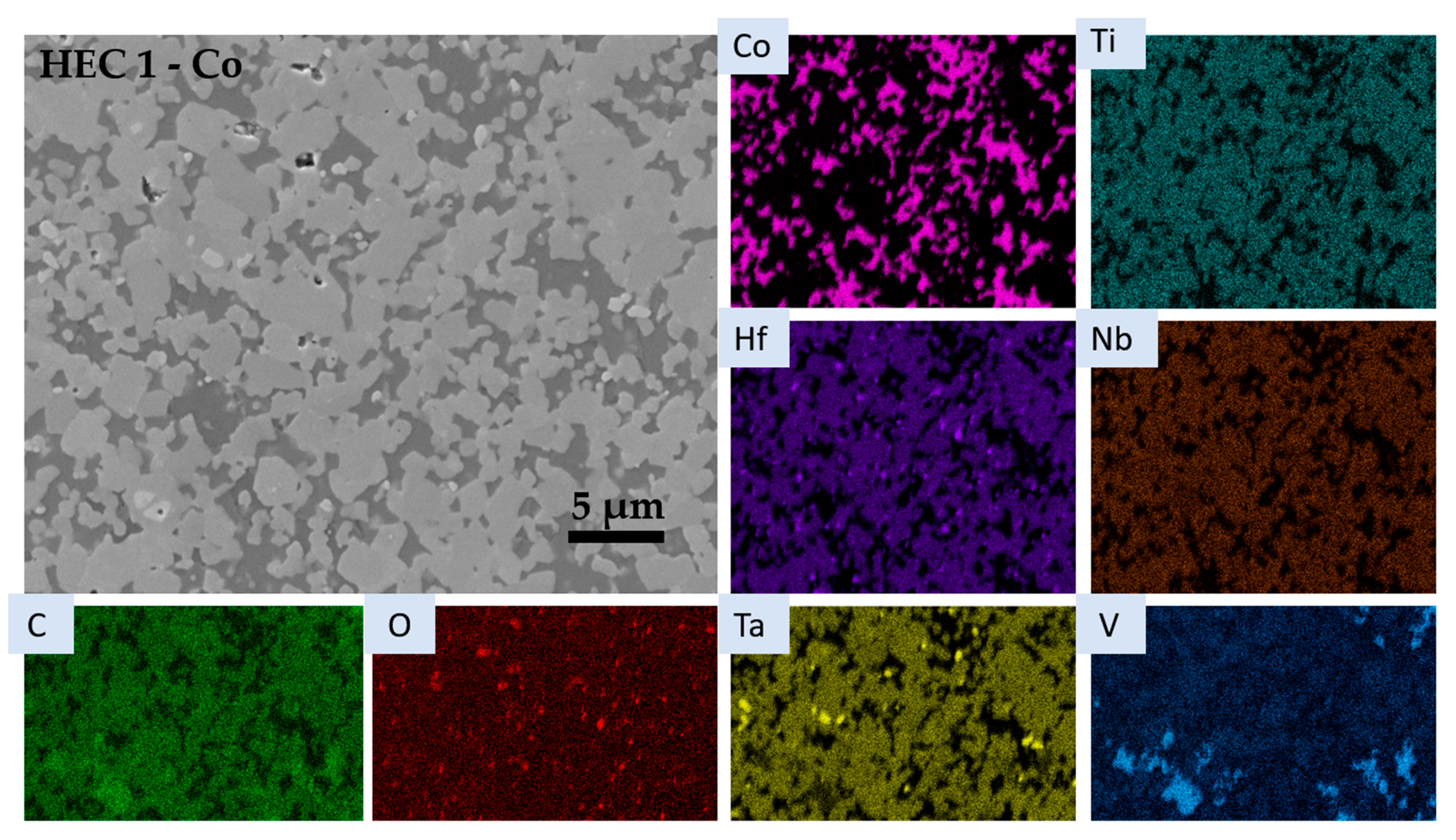
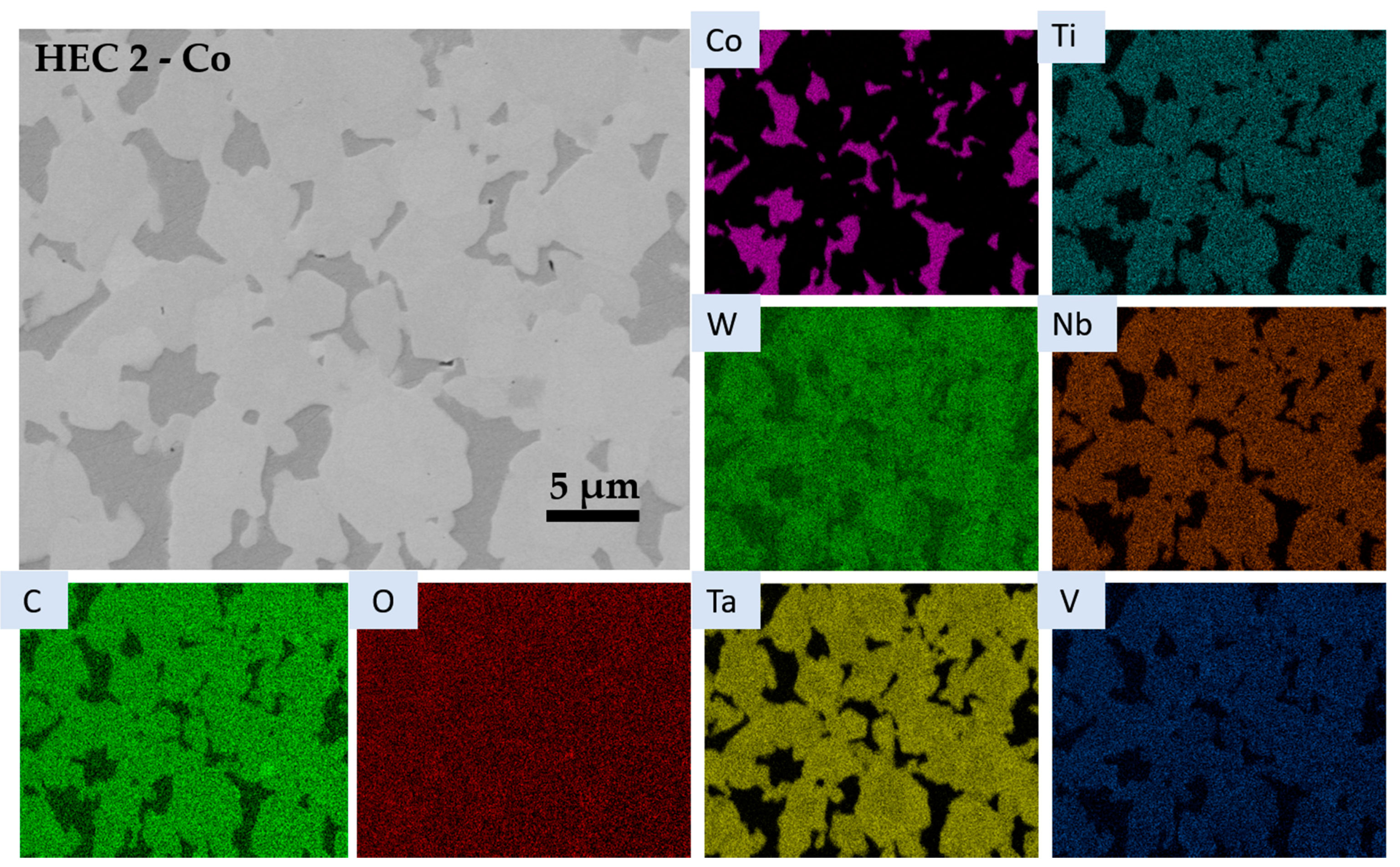
To analyze the distribution of the elements in more detail, EDS mapping was carried out (Figure 5 and Figure 6).
EDS mapping of HEC 1-Co (Figure 5) shows that next to the Co-based binder phase and the HEC phase, three other phases are present in minor quantities. A Ta carbide, as already found in HEC production, is most prominent, and is most likely the product of an insufficient homogenization during HEC production. Furthermore, V-Ti-rich carbide aggregates can be observed in some areas of the sample. Such areas were not spotted during the local EDS analysis of the bulk HEC samples. These aggregates could be the results of either a local precipitation during cooling, as found in V-containing WC-Co hardmetals [40,41], or a locally unfinished solid solution during HEC production. However, no V-Ti-based carbides were found in the prepared HEC powder or in the similarly produced binderless HEC ceramics [39]. The co-presence of Hf and O might point to a Hf-oxide phase. Both phases ((V,Ti) C and HfO2) are in minor quantities, as proven by XRD analysis (Figure 7).
The HEC 2 starting powder consisted of (Ta-Ti-Nb-V-W)C and some excess carbon. However, no excess carbon was detected in the micrographs of the sintered HEC 2-Co (Figure 6). It is expected that the free carbon has been dissolved within the Co binder phase (possible C uptake up to ca. 4.1 at.% [42]) and has to some extent also reduced the surface oxides of the HEC and Co powders during sintering. All HEC starting elements are homogenously distributed in the carbide phase. A slight variation in at least W and Ta can be detected in the color maps of these elements. This might correspond to the light color contrast variation in the carbide grains seen in the electron micrograph. It might refer to a solution precipitation mechanism and the beginning of the formation of a core–rim structure with a slightly W-depleted and slightly Ta-enriched rim area. No formation of separate carbide phases was observed.
Additional semiquantitative EDS-SEM analyses were carried out to obtain information about the stoichiometry of both HEC phases. In the case of HEC 1-Co, 30 HEC grains were measured. The ratios of the carbide-forming metal elements of the HEC 1 phase are given in Table 4. The data show no clear distinction between different compositions of the HEC phase. However, some grains showed a variation in the vanadium content, resulting in the higher standard deviation. There is no distinct difference in the compositions of the different grains. The EDS mapping also revealed some V-rich grains. These grains were also analyzed (Table 4).
In the case of HEC 2-Co, the local formation of a core–rim structure was observed (Figure 6). Regions of the core and the rim were analyzed by measuring the carbide-forming metal elements of the HEC 2 phase of five core and rim areas each. The ratios are given in Table 5 and reveal some W and V depletion in the rim structure. In agreement with the EDS analysis of the binder phase (Figure 4), this suggests that the depletion is caused by the dissolution of W and V within the Co-binder phase.
Furthermore, the oxygen content was measured in all studied HEC grains of HEC 1-Co and HEC 2-Co compositions by semiquantitative EDS-SEM analyses. This was done to investigate, if oxycarbides could have formed. The oxygen content for all 40 measurements varied from 0 to 2 at.% O. With the assumption that most of the measured oxygen came from surface oxides formed after sample polishing, we consequently exclude the formation of a significant incorporation of oxygen in the carbide lattice in our samples.
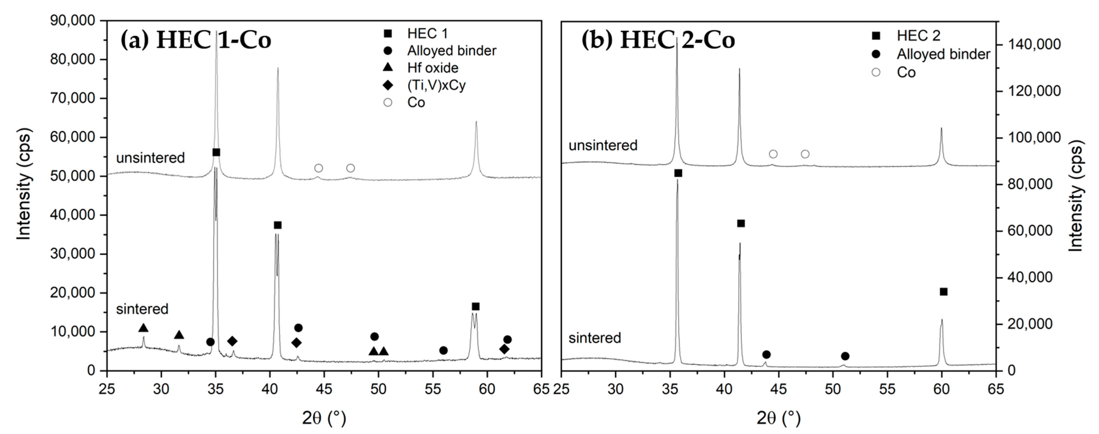
XRD measurements of the starting powder mixtures (as pressed) and of the sintered HEC 1-Co and HEC 2-Co samples are shown in Figure 7a,b. The diffraction pattern of the starting HEC 1-Co mixture (Figure 7a) shows three strong peaks, which correspond to the cubic HEC phase and the small peaks of the added Co phase. There are no matching PDF cards for the specific HEC composition. However, the lattice parameters are similar to the calculated lattice parameters using the rule of mixture (Vegards law) [39]. After sintering, the HEC phase is split up into two very similar phases, both having the cubic Fm-3m structure with very similar lattice parameters (0.4447 nm and 0.4422 nm), corresponding also to the lattice parameter of the HEC phase in the starting powder mixture. There are several other smaller peaks in the sintered HEC 1-Co sample. The peaks at 28.3° and 31.6° indicate the presence of monoclinic HfO2 (PDF 01-075-6426), verifying the results of the EDS mapping in Figure 2. The EDS mapping of the HEC 1-Co sample also showed areas with a carbide enriched in V and Ti. Accordingly, a cubic Fm-3m (Ti,V)C matches the occurring peaks in the XRD pattern. The split-up of the HEC phase into two very similar HEC phases is most likely the result of the formation of the cubic Fm-3m (Ti,V)C phase and the subsequent loss of V and Ti in some HEC 1 grains, which were also observed in the mapping and analyzed by semiquantitative EDS-SEM.
However, this might not be the only reason for the splitting of the peaks of the main carbide phase. Therefore, we assume that the observed splitting could have also been caused by the formation of a core–rim structure which was not detected via SEM and EDS. It could also be caused by the different solubility of the components in Co. A slight adaptation of the starting composition thus might prevent the segregation. However, this needs further investigations.
The EDS analysis also showed that the cobalt binder is alloyed with metal atoms from the cubic carbides such as Ta and V, forming a cubic Co alloy with a changed lattice parameter in comparison to pure Co. This is confirmed by the XRD measurements, where a cubic phase is present with enlarged lattice parameters in comparison to pure Co.
In contrast to the sample HEC 1-Co, only a cubic HEC and a metallic Co-alloy binder were detected by XRD in the sample HEC 2-Co (Figure 7b). The cubic carbide solid solution has an Fm-3m structure. No splitting of the peaks of the HEC phase was observed. A slight HEC peak broadening was observed in the HEC 2-Co sample, most likely corresponding to the observed formation of the core–rim structure for some HEC 2 grains (Figure 6, Table 5). Similar to HEC 1-Co, the Co-binder is alloyed with metal atoms originating from the metal carbides, forming a cubic Co phase with slightly changed lattice parameters.

3.3. Physical and Mechanical Properties of HEC-Co Hardmetals

An ideal high-entropy hardmetal would be one wherein hard phase and binder phase are homogeneously distributed and balanced between hardness and toughness. The hardness and toughness can also be influenced by the carbon content of the sintered hardmetal, which can be measured by magnetic saturation (mS). In addition, the measurement of coercivity (Hc) determines the degree of sintering, cobalt distribution, and grain size of hardmetals. The values of mS, Hc, hardness, and fracture toughness for the produced HEC-Co hardmetals are given in Table 6 in comparison with a WC-12 wt. % Co hardmetal. The theoretical magnetic saturation (mS) was calculated based on the cobalt weight content of both high-entropy hardmetal compositions.
In Table 4, the relative mS for HEC 1-Co (70%) and HEC 2-Co (57.5%) represents a lower limit where the Eta phase would be present in the case of WC-Co hardmetals. However, since it is not clear which of the carbide-forming elements in the HEC hard phase dissolves in the binder phase, a clear assessment cannot be made without a larger variety of added carbon contents. Since no Eta phase of any form was detected by EDS or XRD, it can still be expected that both samples are within a two-phase region of HEC and Co in a corresponding theoretical HEC-Co-C diagram. In the case of a WC-Co hardmetal, the coercivity of ca. 6 and 8 kA/m would correspond to a medium to coarse hardmetal grade of 1.3 to 2.5 µm and 2.5 to 6.0 µm, respectively.
The HV10 hardness values for HEC 1-Co and HEC 2-Co are both lower than for a corresponding medium-grain-sized WC-12 Co hardmetal, due to the larger grain size of the produced materials. Additionally, the measured fracture toughness is somewhat lower than that of the corresponding WC-Co-based hardmetal.

4. Conclusions and Outlook

Due to the growing interest in high-entropy carbides, an investigation of HEC-based hardmetals was done for the first time. Two different high-entropy carbides with the composition (Hf-Ta-Ti-Nb-V)C and (Ta-Ti-Nb-V-W)C were synthesized by a gas pressure sintering technique (also called sinterHIP) at 1950 °C and 100 bar Ar pressure. These high-entropy carbides were crushed to particle sizes less than 20 µm, mixed with 19.2 vol% Co (equivalent to WC-12 wt. % Co), and sintered using a sinterHIP cycle at 1400 °C and 100 bar Ar pressure. The EDS mapping of the resulting dense HEC-based hardmetals with the composition (Hf-Ta-Ti-Nb-V)C-Co (HEC1-Co) showed a homogenous HEC-Co microstructure, as well as a slight amount of undissolved TaC, HfO2, and some larger vanadium–titanium–carbide segregations (already present in the starting HEC).
For the HEC 1-Co material ((Hf-Ta-Ti-Nb-V)C-Co), XRD measurements reveal the formation of a secondary HEC phase with a very similar composition. The reason for the splitting is still not clear, but might be caused by the solution–precipitation process known from hardmetals and cermets, and the formation of a core–rim structure.
However, for the HEC 2-Co material ((Ta-Ti-Nb-V-W)C-Co), homogeneously mixed carbide grains embedded in a binder phase were observed. Only a broadening of the XRD peaks of the HEC phase indicates that the formation of a core–rim structure of the HEC phase started. This is in agreement with the SEM investigation, which revealed a slight depletion of some of the carbide-forming elements in the rim area. A slight adaptation of the starting composition might prevent this process.
The measurement of magnetic saturation indicates for both HEC hardmetals a larger dissolution of HEC-forming elements, with resulting mS values in the range of 60 to 70% as compared to unalloyed cobalt. Coercivity indicated a medium to coarse HEC grain size. The hardness value for HEC 1-Co ((Hf-Ta-Ti-Nb-V)C) is 1200 HV10, while the hardness value for HEC 2-Co ((Ta-Ti-Nb-V-W)C) is 1430 HV10. With up to 8.5 MPa·m1/2, the fracture toughness values are lower than those of WC-Co hardmetals with corresponding hardness. However, with a further carbon adjustment or with other binder compositions such as Ni, Ni, Co, Ni, Mo or Ni, Fe higher fracture toughness values are expected, since Ni has been shown to enhance the mechanical properties in cermets made from cubic hard phases such as TiC, TiCN and NbC [4,44].
Further investigations are necessary to fully understand the microstructure–property relations in these materials. The slightly selective solution–precipitation of some components in certain HECs, for example, might open up possibilities to influence the binder properties and to improve the properties of the material.
In conclusion, dense HEC-based hardmetals have not only been successfully fabricated for the first time by sinterHIP, but for the first time at all. This shows that HEC-based hardmetals can be produced in industrial-style furnaces, which leads to a high number of new possibilities, such as material freedom for the manufacturing of machining tools and other kinds of tools. Future research will focus on the use of directly synthesized HEC powders, different HEC compositions and the use of other binder elements, including high-entropy alloys such as CoCrFeNiCu.

Author Contributions

Conceptualization, J.P. and M.D.; methodology, J.P., A.V. and M.H.; validation, J.P., A.V. and M.H.; formal analysis J.P. and A.V.; investigation, M.D., J.P. and A.V.; data curation, M.D., J.P. and A.V.; writing—original draft preparation, J.P., M.D. and A.V.; writing—review and editing, J.P. and M.H.; visualization, M.D., A.V. and J.P.; supervision, A.M. and M.H.; project administration, J.P. and M.H.; All authors have read and agreed to the published version of the manuscript.

Funding

This research received no external funding.

Institutional Review Board Statement

Not applicable.

Informed Consent Statement

Not applicable.

Acknowledgments

The authors thank Markus Mayer and Daniel Reichenbach as well as Björn Matthey for their help with sample preparations and analysis.

Conflicts of Interest

The authors declare no conflict of interest. The funders had no role in the design of the study; in the collection, analyses, or interpretation of data; in the writing of the manuscript, or in the decision to publish the results.

References

  1. Antonov, M.; Hussainova, P. Chromium carbide based cermets as the wear resistant materials. In Proceedings of the 4th International Conference Industrial Engineeringinnovation as Competitive Edge for SME, Tallinn, Estonia, 29–30 April 2004; pp. 169–172. [Google Scholar]
  2. Huang, S.G.; van der Biest, O.; Li, L.; Vleugels, J. Properties of NbC–Co cermets obtained by spark plasma sintering. Mater. Lett. 2007, 61, 574–577. [Google Scholar] [CrossRef]
  3. Huang, S.G.; Vanmeensel, K.; Mohrbacher, H.; Woydt, M.; Vleugels, J. Microstructure and mechanical properties of NbC-matrix hardmetals with secondary carbide addition and different metal binders. Int. J. Refract. Met. Hard Mater. 2015, 48, 418–426. [Google Scholar] [CrossRef]
  4. Huang, S.G.; Vleugels, J.; Mohrbacher, H.; Woydt, M. NbC grain growth control and mechanical properties of Ni bonded NbC cermets prepared by vacuum liquid phase sintering. Int. J. Refract. Met. Hard Mater. 2018, 72, 63–70. [Google Scholar] [CrossRef]
  5. Montenegro, P.; Gomes, J.; Rego, R.; Borille, A. Potential of niobium carbide application as the hard phase in cutting tool substrate. Int. J. Refract. Met. Hard Mater. 2018, 70, 116–123. [Google Scholar] [CrossRef]
  6. Pötschke, J.; Richter, V.; Mayer, M. Manufacturing and properties of polycrystalline WC-Co based cemented carbides. In Proceedings of the 2016 International Conference on Powder Metallurgy & Particulate Materials, MPIF, Boston, MA, USA, 5–8 June 2016; pp. 457–466. [Google Scholar]
  7. Ettmayer, P. Hardmetals and Cermets. Annu. Rev. Maler. Sci. 1989, 19, 145–164. [Google Scholar] [CrossRef]
  8. Hummer, J. WC-CrC-Co Sintered Composite. Patent No. US3480410A, 15 May 1968. [Google Scholar]
  9. Hashe, N.G.; Norgren, S.M.; Andrén, H.-O.; Neethling, J.H. Characterization of WC–(W,V)C–Co made from pre-alloyed (W,V)C. Int. J. Refract. Met. Hard Mater. 2009, 27, 229–233. [Google Scholar] [CrossRef]
  10. Holleck, H.; Thümmler, F. Eigenschaften von (Ta. Mo)- und (Ta. W)-Mischcarbiden und deren Verhalten zu Bindemetallen. Plansee Semin. 1975, 23, 175–185. [Google Scholar]
  11. Kieffer, R.; Trabesinger, G.; Reiter, N. Über NbC- und HfC-haltige Hartstoffe und Hartmetalle. Plansee Semin. 1969, 17, 25–35. [Google Scholar]
  12. Exner, H. Physical and chemical nature of cemented carbides. Int. Met. Rev. 1979, 4, 149–173. [Google Scholar]
  13. Norgren, S.; García, J.; Blomquist, A.; Yin, L. Trends in the P/M hard metal industry. Int. J. Refract. Met. Hard Mater. 2015, 48, 31–45. [Google Scholar] [CrossRef]
  14. Ettmayer, P.; Kolaska, H. Cermets der neuen Generation. Metall 1989, 43, 742–749. [Google Scholar]
  15. Lengauer, W.; Chen, L.; Gracia, J.; Ucakar, V.; Drezer, K.; Kassel, D.; Daub, H.W. Diffusion controlled surface modification for fabrication of functional gradient (Ti W)C based cemented carbonitrides. Euro Powder Metall. 1999, 3, 475–482. [Google Scholar]
  16. Komac, M.; Kos, K.; Novak, S. Hard Metals Based on Titanium and Molybdenum Carbides. Inst. Mater. Festkörp. 1983, 15, 76–85. [Google Scholar]
  17. Ettmayer, P.; Kolaska, H.; Lengauer, W.; Dreyer, K. Ti(C,N) cermets—Metallurgy and properties. Int. J. Refract. Met. Hard Mater. 1995, 13, 343–351. [Google Scholar] [CrossRef]
  18. Lengauer, W.; Binder, S.; Aigner, K.; Ettmayer, P.; Guillou, A.; Debuigne, J.; Groboth, G. Solid state properties of group IVb carbonitrides. J. Alloy. Compd. 1995, 217, 137–147. [Google Scholar] [CrossRef]
  19. Agnew, S.R.; Dong, L.; Keene, J.I.; Wadley, H.N.G. Mechanical properties of large TiC-Mo-Ni cermet tiles. Int. J. Refract. Met. Hard Mater. 2018, 75, 238–247. [Google Scholar] [CrossRef]
  20. Chen, X.; Xiong, W.; Qu, J.; Yang, Q.; Yao, Z.; Huang, Y. Microstructure and mechanical properties of (Ti,W,Ta)C-xMo-Ni cermets. Int. J. Refract. Met. Hard Mater. 2012, 31, 56–61. [Google Scholar] [CrossRef]
  21. Csanádi, T.; Castle, E.; Reece, M.J.; Dusza, J. Strength enhancement and slip behaviour of high-entropy carbide grains during micro-compression. Sci. Rep. 2019, 9, 10200. [Google Scholar] [CrossRef] [Green Version]
  22. Andrén, H.-O. Microstructures of cemented carbides. Mater. Des. 2001, 22, 491–498. [Google Scholar] [CrossRef]
  23. Holmström, E.; Lizárraga, R.; Linder, D.; Salmasi, A.; Wang, W.; Kaplan, B.; Mao, H.; Larsson, H.; Vitos, L. High entropy alloys: Substituting for cobalt in cutting edge technology. Appl. Mater. Today 2018, 12, 322–329. [Google Scholar] [CrossRef]
  24. De La Obra, A.G.; Avilés, M.A.; Torres, Y.; Chicardi, E.; Gotor, F.J. A new family of cermets: Chemically complex but microstructurally simple. Int. J. Refract. Met. Hard Mater. 2017, 63, 17–25. [Google Scholar] [CrossRef] [Green Version]
  25. Yan, X.; Constantin, L.; Lu, Y.; Silvain, J.-F.; Nastasi, M.; Cui, B. (Hf 0.2 Zr 0.2 Ta 0.2 Nb 0.2 Ti 0.2 )C high-entropy ceramics with low thermal conductivity. J. Am. Ceram. Soc. 2018, 101, 4486–4491. [Google Scholar] [CrossRef]
  26. Castle, E.; Csanádi, T.; Grasso, S.; Dusza, J.; Reece, M. Processing and Properties of High-Entropy Ultra-High Temperature Carbides. Sci. Rep. 2018, 8, 8609. [Google Scholar] [CrossRef] [Green Version]
  27. Harrington, T.J.; Gild, J.; Sarker, P.; Toher, C.; Rost, C.M.; Dippo, O.F.; McElfresh, C.; Kaufmann, K.; Marin, E.; Borowski, L.; et al. Phase stability and mechanical properties of novel high entropy transition metal carbides. Acta Mater. 2019, 166, 271–280. [Google Scholar] [CrossRef] [Green Version]
  28. Feng, L.; Fahrenholtz, W.G.; Hilmas, G.E. Low-temperature sintering of single-phase, high-entropy carbide ceramics. J. Am. Ceram. Soc. 2019, 102, 7217–7224. [Google Scholar] [CrossRef]
  29. Lu, K.; Liu, J.-X.; Wei, X.-F.; Bao, W.; Wu, Y.; Li, F.; Xu, F.; Zhang, G.-J. Microstructures and mechanical properties of high-entropy (Ti0.2Zr0.2Hf0.2Nb0.2Ta0.2)C ceramics with the addition of SiC secondary phase. J. Eur. Ceram. Soc. 2020, 40, 1839–1847. [Google Scholar] [CrossRef]
  30. Wei, X.-F.; Liu, J.-X.; Li, F.; Qin, Y.; Liang, Y.-C.; Zhang, G.-J. High entropy carbide ceramics from different starting materials. J. Eur. Ceram. Soc. 2019, 39, 2989–2994. [Google Scholar] [CrossRef]
  31. Ye, B.; Wen, T.; Nguyen, M.C.; Hao, L.; Wang, C.-Z.; Chu, Y. First-principles study, fabrication and characterization of (Zr0.25Nb0.25Ti0.25V0.25)C high-entropy ceramics. Acta Mater. 2019, 170, 15–23. [Google Scholar] [CrossRef] [Green Version]
  32. Bao, W.; Wang, X.-G.; Ding, H.; Lu, P.; Zhu, C.; Zhang, G.-J.; Xu, F. High-entropy M2AlC-MC (M=Ti, Zr, Hf, Nb, Ta) composite: Synthesis and microstructures. Scr. Mater. 2020, 183, 33–38. [Google Scholar] [CrossRef]
  33. Wang, K.; Chen, L.; Xu, C.; Zhang, W.; Liu, Z.; Wang, Y.; Ouyang, J.; Zhang, X.; Fu, Y.; Zhou, Y. Microstructure and mechanical properties of (TiZrNbTaMo)C high-entropy ceramic. J. Mater. Sci. Technol. 2020, 39, 99–105. [Google Scholar] [CrossRef]
  34. Feng, L.; Fahrenholtz, W.G.; Hilmas, G.E.; Zhou, Y. Synthesis of single-phase high-entropy carbide powders. Scr. Mater. 2019, 162, 90–93. [Google Scholar] [CrossRef]
  35. Chicardi, E.; García-Garrido, C.; Gotor, F.J. Low temperature synthesis of an equiatomic (TiZrHfVNb)C5 high entropy carbide by a mechanically-induced carbon diffusion route. Ceram. Int. 2019, 45, 21858–21863. [Google Scholar] [CrossRef]
  36. Chicardi, E.; García-Garrido, C.; Hernández-Saz, J.; Gotor, F.J. Synthesis of all equiatomic five-transition metals High Entropy Carbides of the IVB (Ti, Zr, Hf) and VB (V, Nb, Ta) groups by a low temperature route. Ceram. Int. 2020, 46, 21421–21430. [Google Scholar] [CrossRef]
  37. García, J.; Collado Ciprés, V.; Blomqvist, A.; Kaplan, B. Cemented carbide microstructures: A review. Int. J. Refract. Met. Hard Mater. 2019, 80, 40–68. [Google Scholar] [CrossRef]
  38. Shetty, D.K.; Wright, I.G.; Mincer, P.N.; Clauer, A.H. Indentation fracture of WC-Co cermets. J. Mater. Sci. 1985, 20, 1873–1882. [Google Scholar] [CrossRef]
  39. Pötschke, J.; Dahal, M.; Herrmann, M.; Vornberger, A.; Matthey, B.; Michaelis, A. Preparation of High Entropy Carbides by Different Sintering Techniques. J. Mater. Sci. 2021. under review. [Google Scholar]
  40. Pötschke, J.; Mayer, M.; Richter, V. Formation of carbide segregations in nanoscaled hardmetals. In Proceedings of the Euro PM 2015: International Power Metallurgy Congress and Exhibition, Reims, France, 4–7 October 2015. [Google Scholar]
  41. Toufar, C.; Schubert, W.D.; Hashiya, M.; Kubo, Y. On the Formation of Precipitations in Highly (Cr,V)-doped Cemented Carbides. In Proceedings of the 18th International Plansee Seminar, Reutte, Austria, 3–7 June 2013; Sigl, L.S., Kestler, H., Wagner, J., Eds.; Plansee SE: Reutte, Austria, 2013. [Google Scholar]
  42. Fernandez Guillermet, A. Thermodynamic Analysis of the Co-C System. In Zeitschrift für Metallkunde; Hanser: Munich, Germany, 1987; Volume 78, pp. 700–709. [Google Scholar]
  43. Vornberger, A.; Pötschke, J.; Gestrich, T.; Herrmann, M.; Michaelis, A. Influence of microstructure on hardness and thermal conductivity of hardmetals. Int. J. Refract. Met. Hard Mater. 2020, 88, 105170. [Google Scholar] [CrossRef]
  44. Woydt, M.; Huang, S.G.; Vleugels, J.; Mohrbacher, H.; Cannizza, E. Potentials of niobium carbide (NbC) as cutting tools and for wear protection. Int. J. Refract. Met. Hard Mater. 2018, 72, 380–387. [Google Scholar] [CrossRef]
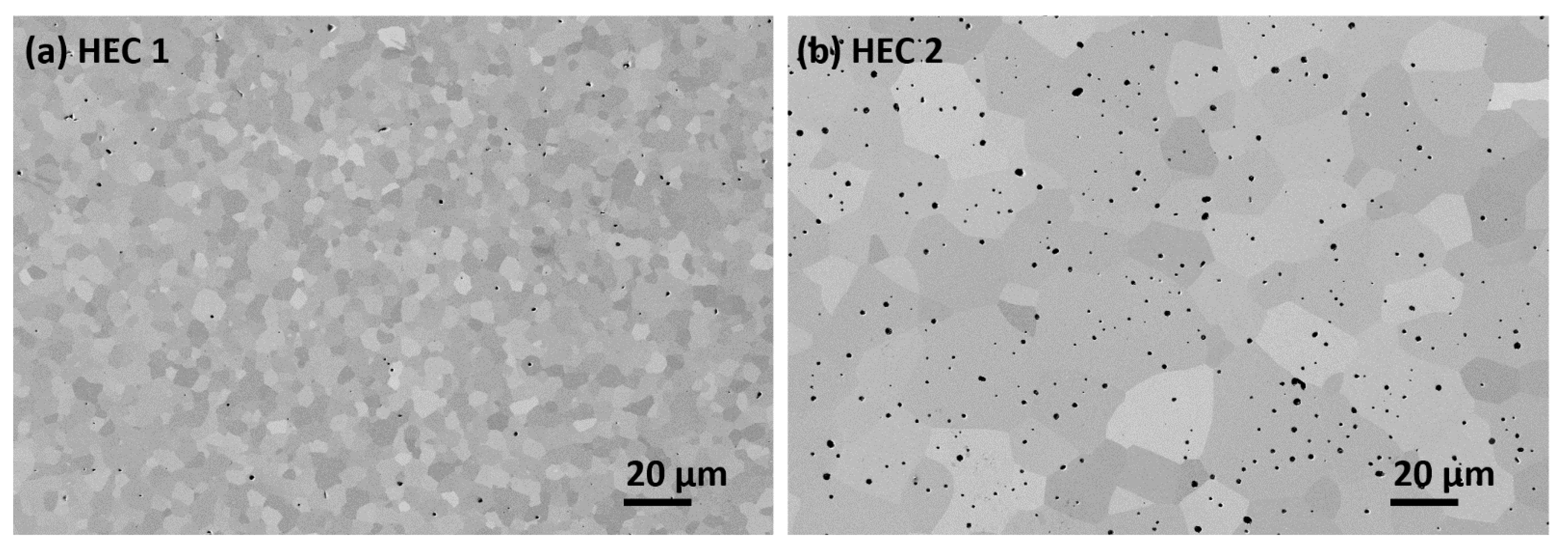
Figure 1. Micrographs of produced high-entropy carbides with sinterHIP cycle with (a) HEC 1 composition (Hf-Nb-Ta-Ti-V)C and (b) HEC 2 composition (Ta-Nb-Ti-V-W)C before crushing and sieving.
Metals 11 00271 g001
Figure 2. Micrographs of HEC-Co samples: (a) HEC 1-Co (composition: (Hf-Ta-Ti-Nb-V)C and Co) (b) HEC 2-Co (composition: (Ta-Ti-Nb-V-W)C and Co) both sintered with sinterHIP cycle at 1400 °C and 100 bar Ar pressure. (The dark gray phase is the cobalt binder, see also Figure 3, Figure 4, Figure 5 and Figure 6).
Metals 11 00271 g002
Figure 3. (a) Backscattered electron micrograph of HEC 1-Co with EDS mapping, (b) EDS result of dark phase consisting of Co with mixed metals, (c) EDS result of gray phase with mixed carbides, (d) EDS result of light gray phase with Ta and (e) EDS result of gray phase with Hf.
Metals 11 00271 g003
Figure 4. (a) Backscattered electron micrographs of HEC 2-Co with (b) EDS result of dark phase consisting of Co with mixed metals, (c) EDS result of gray phase with mixed carbides with high concentration of W, (d) EDS result of light gray phase same as (c).
Metals 11 00271 g004
Figure 5. EDS micrographs of HEC 1-Co (composition: (Hf-Ta-Nb-Ti-V)C and Co, co-sintered with sinterHIP at 1400 °C and 100 bar Ar pressure).
Metals 11 00271 g005
Figure 6. EDS micrographs of HEC 2-Co (composition: (Ta-Nb-Ti-V-W)C and Co, co-sintered with sinterHIP at 1400 °C and 100 bar Ar pressure).
Metals 11 00271 g006
Figure 7. X-ray diffraction pattern of pressed (unsintered) and sintered (a) HEC 1-Co (composition: (Hf-Ta-Nb-Ti-V)C and 19.2 vol% Co) and (b) HEC 2-Co (composition: (Ta-Nb-Ti-V-W)C and 19.2 vol% Co) with 2Theta ranging between 25 and 65 degrees. Note: The labeled HEC 1 phase is in reality a mixture of two cubic carbide phases with very similar lattice parameters.
Metals 11 00271 g007
Table 1. Compositions of HEC as a precursor to manufacture HEC-Co.
HEC SamplesCompositions (wt. %)
HfCTaCNbCTiCVCWC
HEC 131.231.617.29.810.3-
HEC 2-31.317.09.710.231.8
Table 2. Characteristics of the used starting powders (* data from the suppliers’ datasheets).
PowdersSupplierParticle Size
dFSSS (µm)
Specific Surface Area BET (m2/g)dBET (nm)O2 Content (wt. %)
HfCSigma-Aldrich0.63.91331.72
TaCH.C. Starck1.01.13660.13 *
NbCGTP1.21.26390.25 *
TiCH.C. Starck2.42.06190.37 *
VCH.C. Starck1.23.03500.80 *
WCH.C. Starck0.52.61490.26 *
Table 3. Density of prepared samples HEC 1-Co and HEC 2-Co.
Hardmetal
Samples
Sintering ConditionsTheoretical Density (g/cm3)Archimedes Density (g/cm3)Relative Density (%)
HEC 1-19.2 vol% CosinterHIP
1400 °C/100 bar Ar
9.189.1599.6
HEC 2-19.2 vol% Co9.649.74101.0
Table 4. Metal content (at.%) of HEC grains in HEC 1-Co determined by EDS-SEM.
ElementTiVNbHfTa
Main phase
Mean value/at.%20.218.221.519.320.9
Standard deviation0.93.21.21.11.9
V- rich phase
Mean value/at.%14.766.99.61.37.5
Standard deviation0.52.40.90.31.0
Table 5. Metal content (at.%) of core and rim areas of HEC grains in HEC 2-Co determined by EDS-SEM.
ElementTiVNbTaW
Core
Mean value/at.%18.319.521.220.420.7
Standard deviation0.40.60.40.40.4
Rim
Mean value/at.%21.416.822.822.116.9
Standard deviation1.10.80.71.02.0
Table 6. Physical and mechanical properties of HEC-Co hardmetals.
SamplesmS
/µT·m3·kg−1
mS
/(% theo)
Hc
/kA/m
HardnessFracture Toughness K1C/MPa·m1/2
/HV10GPa
HEC 1-19.2 vol% Co30.070.05.61203 ± 1511.808.5 ± 0.2
HEC 2-19.2 vol% Co20.757.58.41432 ± 1014.046.7 ± 0.2
WC-19.2 vol% Co [43]19.985.019.91460 ± 1514.3214.3 ± 0.2
Publisher’s Note: MDPI stays neutral with regard to jurisdictional claims in published maps and institutional affiliations.