Abstract
In the present work, the influence of the cooling time on the mechanical performance, hardness, and microstructural features of a double pulse resistance spot welded medium-Mn steel are investigated. Curves of the electrical resistance throughout the welding revealed that the cooling time strongly influences the heat generation during the second pulse. A second pulse after a short cooling time re-melts the center, and heat treats the edge of the primary fusion zone. This desired in-process heat treatment leads to a modification of the cast-like martensitic structure by recrystallization illustrated by electron backscatter diffraction measurements and to a homogenization of manganese segregations, visualized by energy-dispersive X-ray spectroscopy, which results in an enhanced mechanical performance during the cross tension strength test. In contrast, during excessively long cooling times, the resistance drops to a level where the heat generation due to the second pulse is too low to sufficiently re-heat the edge of the primary FZ. As a consequence, the signs of recrystallization disappear, and the manganese segregations are still present at the edge of the fusion zone, which leads to a deterioration of the mechanical properties.
1. Introduction
As a representative of the third generation of advanced high strength steels (AHSS), medium-Mn steels, with an increased but still moderate amount of manganese of 4–10 wt% and a carbon content of 0.2 wt% or less, are considered suitable to fulfill the requirements for body components in the automotive industry [1,2,3,4]. First introduced in 1972 by Miller [5], research on this steel grade has been intensified in recent years [4,6,7,8,9]. Their superior mechanical properties are achieved by a ferritic microstructure with a high amount of retained austenite of usually more than 30%, which is stabilized by manganese enrichment at intercritical annealing [4,6,8,10]. A high fraction of retained austenite is essential to combine high strength and ductility by means of the transformation-induced plasticity (TRIP) effect [8,9].
Because of the high operating speed and the suitability for automation, resistance spot welding (RSW) is the dominant technology for sheet metal joining in the automotive industry [11], and therefore, research regarding the weldability of medium-Mn steels is decisive. However, only few related studies have been published so far [12,13,14,15]. Due to the rapid cooling combined with the relatively high alloying content of medium-Mn steels, they tend to form a hard and brittle martensitic fusion zone (FZ), which leads to a poor tensile-shear strength of the welds [12] and to insufficient mechanical properties during the cross-tension strength (CTS) test with low maximum force and an interfacial failure (IF) mode [13]. The failure mode changes to a pullout failure (PF) for dissimilar resistance spot weldments of a medium-Mn and dual phase steel, with the crack propagating through the brittle, martensitic coarse-grained heat-affected zone (CGHAZ) of the medium-Mn steel. This zone has a significantly lowered content of retained austenite compared to the base metal [13]. However, the brittleness of the CGHAZ could be reduced by nano-scale austenite reversion during a paint baking heat treatment, which led to enhanced mechanical properties of the welds [14]. Another work focused on the softening of the CGHAZ by means of various thermo-mechanically simulated in-situ tempering heat treatment cycles. Again the nano-scale austenite reversion led to an increase of the ductility of this zone and to the transition from a brittle to a ductile fracture [15].
A widely accepted approach to improve the mechanical performance of third generation AHSS welds is to add an additional pulse after the main pulse to carry out an in-process heat treatment of the welds, also known as double pulsing [16,17,18,19,20,21,22]. In previous works [22,23], the authors examined the microstructural evolution and the mechanical performance of the FZ and heat-affected zone (HAZ) of a double pulse welded 1.2 GPa TRIP-aided bainitic ferrite (TBF) steel. It was shown that a low current second pulse after a very long cooling time between the pulses tempers, and therefore, softens the weldment, while a high current second pulse after a short cooling time, hereinafter referred to as a recrystallization pulse, recrystallizes the edge of the FZ. Due to a shorter process time, research mainly focused on the concept of the recrystallization pulse in recent years [16,17,18,19,21], although both double pulsing concepts are capable of improving the mechanical performance of AHSS spot welds [23]. During the second pulse, the cast-like structure at the edge of the FZ recrystallizes, resulting in more equiaxed prior austenite grains (PAGs) and in a refinement of the martensitic blocks, which improves the toughness due to enhanced crack deflection [17]. Further, the second pulse homogenizes the segregations of phosphorus and also manganese in the FZ, and therefore, diminishes the risk of intergranular failure [18]. Chabok et al. [16] attributed the improved mechanical performance of a double pulse welded DP1000 dual-phase steel to the lowered residual strain at the edge of the FZ and the increased number of high angle grain boundaries in the upper critical heat-affected zone (UCHAZ), which is also assumed to increase the toughness.
Consequently, double pulsing might also represent a promising approach to overcome the poor weldability of medium-Mn steels. However, the influence of the significantly increased manganese content compared to other representatives of the third generation AHSS has to be taken into account, and there is especially a lack of publications in the literature dealing with the exact role of the cooling time between pulses, which makes it difficult to choose the optimal parameters. The main focus of this work is, therefore, on the role of the cooling time with regard to the heat generation during the second pulse, and its influence on the microstructural features and especially the manganese distribution at the edge of the FZ and the resulting mechanical properties of a resistance spot welded medium-Mn steel, which, to our knowledge, has never been published before.
For this purpose, single and double pulse welding experiments with increasing cooling time between the pulses were performed, and the heat generation during the second pulse was evaluated based on the dynamic resistance curves. The mechanical performance of the welds was assessed by CTS tests, and hardness mappings were conducted to comprehend the influence of double pulsing with different cooling time on the hardness distribution. Picric acid etching and electron backscatter diffraction (EBSD) measurements were used to visualize the influence of the welding parameters on the microstructure. Moreover, the manganese distribution was measured via energy-dispersive X-ray spectroscopy (EDX). Combining these methods, a correlation of the cooling time between the pulses, the microstructure, and the mechanical performance is drawn.
2. Materials and Methods
A medium-Mn steel with a nominal composition of 0.1 C/6.4 Mn/0.6 Si (wt%), an aluminum content of <400 ppm, and a phosphorus and sulfur content of combined less than 120 ppm was investigated. This steel possesses a minimum tensile strength of 780 MPa with a yield strength of about 650 MPa and an elongation of about 34%. The uncoated steel sheets had a thickness of 1.18 mm. RSW was performed on a Nimak MFDC-1000 Hz pedestal type welding machine (Nimak GmbH, Wissen, Germany) equipped with an AutoSpatz regulator (Matuschek, Alsdorf, Germany) that delivered a constant current. The resulting voltage was measured at the electrode and the resulting resistance as a function of time was calculated with the adjusted current. The F1-16-20-6 electrodes operated at a clamping force of 4.0 kN as recommended in VDEh SEP1220-2 [24]. The samples in the present work were welded with a current of 4.8 kA, which is the current high enough to produce a FZ that fulfills the quality criterion of a minimum diameter of 4*√t, where t is the sheet thickness. This current was used for the first pulse, as well as for the second pulse. A schematic illustration of the different welding sequences is presented in Figure 1. For all welds, prior to the first pulse, a squeeze time of 600 ms was applied, the pulse time was 280 ms, and the hold time after the final pulse was 200 ms. The variable cooling time between the pulses was 20, 50, 100, 200, and 500 ms.
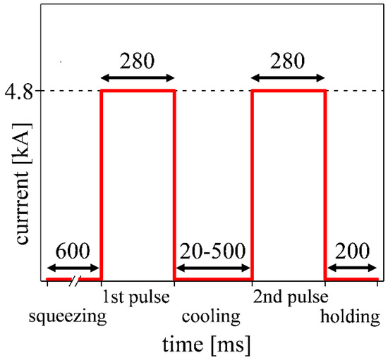
Figure 1.
Schematic illustration of the welding sequence with variable cooling times.
The mechanical performance was evaluated via standard CTS tests [24] (sample size of 50 × 150 mm2) and the results represent the average of five tests. The maximum force, Fmax, and the pullout ratio, which is the areal fraction of the pulled-out plug to the former welded lens, were measured with a caliper after failure.
For microstructural characterization, light optical microscope (LOM) images were taken with an M1M Imager equipped with an AxioCam MRc5 camera, both from Zeiss (Oberkochen, Germany). For this purpose, cross-sections were ground, polished, and finally, etched with a mixture of cold saturated picric acid, dodecylbenzenesulfonate, and hydrochloric acid to reveal the solidification structure.
Hardness mappings were performed on a Q60A+ hardness tester from Qness (Golling, Austria). The distance between the indents was 150 µm, the load was 300 g, and the dwell time 10 s.
For the EBSD measurements, the sample preparation included final OPU suspension polishing for 10 min in order to get a deformation free surface. The measurements were performed on a scanning electron microscope (SEM) VERSA 3D from FEI (Hillsboro, OR, USA) equipped with an EDAX Hikari EBSD system operating at a working distance of 15 mm and an acceleration voltage of 20 kV. The step size of the EBSD mappings with an area of 500 × 500 µm2 was 500 nm. The software package EDAX OIM Analysis 7 (EDAX Inc., Mahwah, NJ, USA) was used for data evaluation. The data sets were cleaned via grain dilation, and neighbor confidence index (CI) standardization clean-ups and data points with a CI of less than 0.1 were disregarded. ARPGE software package [25] was used to reconstruct the PAGs.
Energy-dispersive X-ray spectroscopy was performed at an acceleration voltage of 15 kV on a Tescan SEM of the type CLARA (Tescan, Brünn, Czech Republic) combined with the X-Max system and the Aztec software from Oxford Instruments (Abingdon, UK). Since the conventional EDX measurements only allow a qualitative statement, the numerical values of the manganese content were determined with a post-processing step by the software package but without claiming to achieve the extremely high accuracy of an EPMA system.
3. Results
3.1. Cross-Tension Strength Tests
The influence of the cooling time on the mechanical performance of the welds was determined with CTS tests and the results are depicted in Figure 2. The maximum force, Fmax, and the pullout ratio hereinafter quantify the mechanical performance of the welds. A pullout ratio of 0% is referred to as an IF and a fraction of pullout of 100% represents a PF. A pullout ratio between these limits is a partial interfacial failure (PIF). The single pulse samples, referred to as “sp” in Figure 2, reach a Fmax of 3.0 kN and the pullout ratio averages 26%. In contrast, the double pulse welds with relatively short cooling times of 20, 50, and 100 ms between the pulses bear significantly higher loads of 6.0, 6.3, and 5.8 kN and the pullout ratio after CTS testing is 27%, 45%, and 31%, respectively. However, it has to be stated that, for all welds, the standard deviation of the pullout ratio is relatively high. With longer cooling times of 200 and 500 ms, Fmax decreases to 4.1 and 4.3 kN with a pullout ratio of 40% and 56%, respectively.
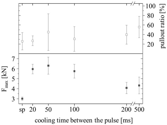
Figure 2.
Average maximum force, Fmax, and pullout ratio in CTS tests of single pulse welds (sp) compared to double pulse welds with different cooling times (n = 5).
3.2. Light Optical Microscopy
By means of the picric acid-etched cross-sections depicted in Figure 3, the influence of the cooling time on the evolution of the FZ during the second pulse was examined. The black arrows indicate the width of the primary and the red arrows indicate the width of the secondary FZ, which re-melts during the second pulse. The width of the FZ of the single pulse weld in Figure 3a is 4.1 mm, and therefore, slightly smaller than the nominal minimum FZ size of 4.35 mm calculated from the 4*√t quality criterion. The black arrows in Figure 3b–f illustrate that the size of the primary FZ does not change significantly due to double pulsing. However, the size of the secondary FZ decreases with increasing cooling time. While 3.7 mm of the initial 4.2 mm are re-melted by the second pulse after a cooling time of 20 ms in Figure 3b, only 3.1 and 1.2 mm are re-melted after a cooling time of 50 and 100 ms, as shown in Figure 3c,d. After longer cooling times of 200 ms in Figure 3e and 500 ms in Figure 3f, there is no secondary FZ clearly visible.
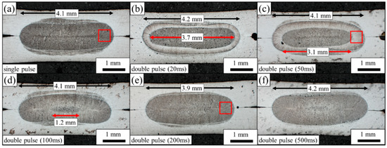
Figure 3.
LOM images of the cross-sections of (a) single pulse weld and double pulse welds with a cooling time of (b) 20 ms, (c) 50 ms, (d) 100 ms, (e) 200 ms, and (f) 500 ms. The black arrows represent the width of the primary FZ and the red arrows the width of the secondary FZ, if present. The red boxes in (a,c,e) mark the areas where EBSD scans were taken.
3.3. Dynamic Resistance Curves
The heat generation, Qw in joules, during resistance spot welding is based on Joule’s law. Since the welding current and the welding time stay constant, the equation can be written as
where I is the electrical current in amperes, R(T) the temperature-dependent, and therefore, dynamic electrical resistance in ohms and t the welding time in seconds. While the electric current and the welding time are given by the operator, the dynamic resistance curve can be recorded to estimate the heat development during welding according to Equation (1). Online monitoring of the dynamic resistance is, therefore, a powerful tool in terms of process control [26,27,28]. In the course of the present work, the dynamic resistance curves were primarily recorded to evaluate the influence of the various cooling times on the temperature prior and the heat generation during the second pulse. The resistance curve of the single pulse weld is shown in Figure 4a. As suggested by Dickinson et al. [29], the first peak in the resistance curve represents the contact resistance, which is 250 µΩ in the case of the medium-Mn steel sheets under investigation. It breaks down within a few milliseconds to 150 µΩ, the so-called α-trough. Then the increasing temperature results in a continuous increase of the resistance, but with progressing time also in local melting, which lowers the resistance due to an increasing cross-sectional area available for the current flow. The so-called β-peak of 190 µΩ represents the point where the temperature stabilizes, and the nugget growth begins to dominate. After the β-peak, the resistance continuously decreases due to the increasing nugget size to a final resistance of 115 µΩ. The resistance curves of the second pulse after various cooling times are presented in Figure 4b–f. After a short cooling time of 20 and 50 ms, the resistance drops slightly to 100 and 90 µΩ and stays constant during the second pulse, as can be seen in Figure 4b,c. After a longer cooling time of 100 ms, the resistance is 70 µΩ at the beginning of the second pulse and rises continuously to 80 µΩ in Figure 4d. The resistance drop is even more pronounced after cooling times of 200 and 500 ms. It decreases to 40 and 30 µΩ at the beginning of the second pulse and reaches a final resistance of 70 and 60 µΩ, as can be seen in Figure 4e,f, respectively. The continuously decreasing resistance illustrates that the temperature at the beginning, and consequently the heat generation during the second pulse, decreases with longer cooling times between the pulses.
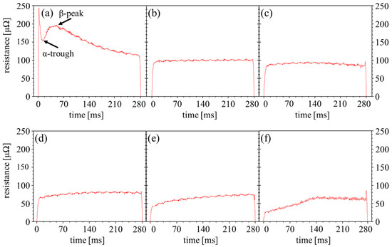
Figure 4.
Dynamic resistance curves recorded during the (a) single pulse and the second pulse after a cooling time of (b) 20 ms, (c) 50 ms, (d) 100 ms, (e) 200 ms and (f) 500 ms.
3.4. Hardness Mapping
Hardness mappings with several hundred indents, as depicted in Figure 5, were conducted on representative samples to verify the effect of double pulsing on the hardness distribution of the medium-Mn steel welds. For the single pulse weld in Figure 5a the hardening of the FZ, with a hardness of 420–430 HV, is very pronounced compared to the hardness of about 280 HV of the BM. The hardness in the UCHAZ reaches up to 460 HV before dropping to 370 HV in the intercritical heat-affected zone (ICHAZ). Since the BM does not contain martensite, there is no softening of the subcritical heat-affected zone (SCHAZ). The double pulse welds with a cooling time of 50 ms in Figure 5b and 200 ms in Figure 5c show an almost identical hardness distribution, although a slight softening of about 10–20 HV can be observed in the outer regions of the FZ. Moreover, the ICHAZ after 200 ms cooling time in Figure 5c seems to be wider. The ICHAZ further broadens with a longer cooling time of 500 ms, as shown in Figure 5d. It is about twice as big as the width of the ICHAZ of the 50 ms double pulse weld in Figure 5b.
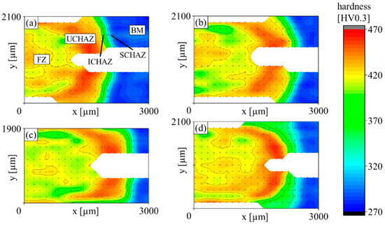
Figure 5.
Hardness mappings of the (a) single pulse weld and double pulse weld with a cooling time of (b) 50 ms, (c) 200 ms, and (d) 500 ms.
3.5. Electron Backscatter Diffraction
To analyze the structure of the prior austenite grains (PAGs) at the edge of the FZ, EBSD scans of areas of 500 × 500 µm2 of the single pulse weld and the double pulse welds with a cooling time of 50 and 200 ms were conducted, as marked by red boxes in Figure 3a,c,e. The corresponding IPF maps of the bcc phase, which represents the low carbon martensite, with the reconstructed PAGs being highlighted with bold black lines, are depicted in Figure 6. As can be seen in Figure 6a, the edge of the FZ after the single pulse consists of the typical cast-like structure with elongated PAGs oriented along the maximum heat dissipation. After a 50 ms lasting cooling time, the second pulse leads to a noticeable coarsening of the PAGs, and the elongation, especially of the PAGs in the center of the scan, diminishes in Figure 6b. By extending the cooling time to 200 ms, the PAGs are again more elongated and finer compared to the weld with a 50 ms cooling time and rather resemble the PAGs of the single pulse weld.
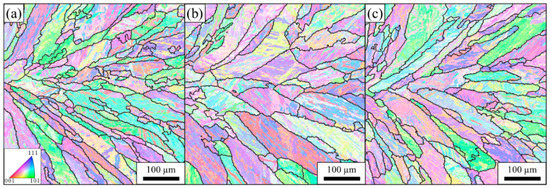
Figure 6.
IPF maps of the bcc phase of the areas indicated by red boxes in Figure 3 for the (a) single pulse weld and the double pulse welds with a cooling time of (b) 50 ms and (c) 200 ms. The bold black lines represent the PAGs.
3.6. Energy-Dispersive X-Ray Spectroscopy
In order to visualize the distribution of manganese, EDX scans were conducted and manganese segregations, which are only a few micrometers wide, were detected. In the center of the FZ of the single pulse weld, the manganese segregations are oriented in vertical direction towards the electrodes and reach a manganese content of 9 to 11 wt%, as can be derived from the EDX mapping depicted in Figure 7. The areas between the segregations are consequently slightly depleted in manganese compared to the nominal content of 6.4 wt% and have an average content of 5 to 6 wt%.
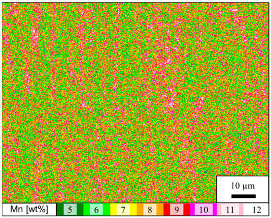
Figure 7.
EDX mapping of the manganese distribution of the center of the FZ of the single pulse weld.
Because the edge of the FZ undergoes the in-process heat treatment due to the second pulse, the manganese distribution of this zone was also measured for the single pulse weld and the representative double pulse welds with cooling times of 50 and 200 ms and the results are depicted in Figure 8. At the edge of the FZ of the single pulse weld, the morphology of the segregations changes to a mainly horizontal, honeycomb-like arrangement, as shown in Figure 8a. The segregations are very fine and reach a maximum manganese content of about 9 wt% on average. The manganese distribution at the edge of the FZ of the double pulse weld with a cooling time of 50 ms is much more homogeneous, as indicated by Figure 8b. Even the few segregations in the lower third of the imaged area are not very pronounced and have a maximum manganese content of 7 to 8 wt%. Consequently, the manganese content of the remaining areas is higher and close to the nominal content. Double pulsing with a cooling time of 200 ms leads to an edge of the FZ with pronounced segregations of manganese, as illustrated by Figure 8c. They are mainly horizontally aligned and reach an average maximum manganese content of about 9 wt% with depleted areas in between.
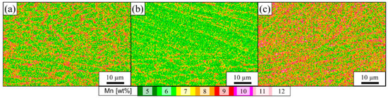
Figure 8.
EDX mappings of the manganese distribution at the edge FZ of the (a) single pulse weld and the double pulse welds with a cooling time of (b) 50 ms and (c) 200 ms.
4. Discussions
The aim of the present work was to investigate the improvement of the mechanical performance and the characteristics of the microstructure due to double pulsing with different cooling times. The mechanical performance in terms of Fmax (3.0 kN) and the pullout ratio (26%) of the single pulse welded medium-Mn steel, as shown in Figure 2, is unsatisfactory. Therefore, the results of the CTS tests in Figure 2 indicate that relatively short cooling times of 20, 50 or 100 ms lead an increased Fmax. With 6.0, 6.3, and 5.8 kN, the maximum force is roughly doubled compared to the single pulse weld. With longer cooling times of 200 and 500 ms, Fmax decreases again to 4.1 and 4.3 kN, respectively. Improved properties due to a very short cooling time are in agreement with the literature, where enhanced mechanical properties of AHSS spot welds were reported due to double pulsing with a cooling time of 40 ms [16,18,19]. Surprisingly, the pullout ratio appears not to correlate with the cooling time, scatters strongly, and is not significantly improved due to double pulsing.
The width of the secondary FZ is reported to depend on the heat input during the second pulse, which is mainly influenced by the applied current [18,19]. In the present work, it is shown that the heat input of the second pulse also strongly depends on the cooling time in between the pulses, even at the same current levels, due to the temperature dependence of the electrical resistance. As indicated by the images of the etched cross-sections in Figure 3, the width of the secondary FZ, and therefore, the heat input due to the second pulse, decrease successively with increasing cooling time. A secondary FZ is only visible for short cooling times of up to 100 ms, which results in the highest Fmax and it disappears for longer cooling times. The presence of a secondary FZ is, therefore, a good indicator in terms of estimating the improvement of mechanical properties of the double pulse welds. The decrease of the heat input during the second pulse with increasing cooling times can also be derived from the resistance curves depicted in Figure 4. The resistance at the end of the single pulse in Figure 4a, which also represents the first pulse of each double pulse weld, is 115 µΩ. The resistance at the beginning of the second pulse depends on the temperature of the weld after the cooling time and affects the amount of heat generated during the second pulse, as can be derived from Equation (1). It successively decreases with increasing cooling time. With 100 and 90 µΩ, after short cooling times of 20 and 50 ms, the resistance, and therefore, the temperature at the beginning of the second pulse, are still high enough to cause partial re-melting of the primary FZ during the second pulse. After a longer cooling time of 200 ms, the resistance drops to 40 µΩ, which seems to be too low to generate sufficient heat during the second pulse to achieve the intended in-process heat treatment. The insufficient heat generation during the second pulse after a long cooling time is also evidenced by the hardness mappings. While the ICHAZ of the double pulse weld with a cooling time of 50 ms is narrow, the ICHAZ after a long cooling time, especially after 500 ms, is broad. This indicates that the intercritical temperature was reached at a closer distance to the FZ during the second pulse because less heat was generated.
While in dissimilar weldments the crack propagated through the CGHAZ of the medium-Mn steel [14,15], in the present work, the crack propagated through the edge of the FZ. Therefore, this zone was considered crucial and characterized in more detail. Generally, if the second pulse is correctly applied, it leads to the desired recrystallization of the edge of the primary FZ and to a more equiaxed PAG structure, which can be visualized using EBSD measurements [16,17,19,22]. Figure 6b shows that the edge of the primary FZ of the double pulse weld with a 50 ms cooling time consists of coarser and more equiaxed grains than the single pulse weld in Figure 6a. Especially the grains in the center of the image show signs of recrystallization due to the high temperature in this zone during the second pulse. The improved mechanical properties of these samples in Figure 2 are in good agreement with the literature, since more equiaxed PAGs are considered to promote crack deflecting, which results in enhanced toughness [16,17,22]. However, it has to be mentioned that the signs of recrystallization are not as pronounced as expected based on preliminary EBSD investigations on another AHSS grade [22]. This may be due to the lower carbon content in the medium-Mn steel, which is associated with a lower dislocation density of the martensite in the FZ and thus provides fewer nucleation sites for recrystallization. By extending the cooling time to 200 ms, the heat input during the second pulse decreases, as explained above, and the signs of recrystallization, therefore, completely disappear, as shown by Figure 6c. The reconstruction resembles the cast-like PAGs of the single pulse weld in Figure 6a, and the mechanical performance is inferior to the performance of the double pulse weld with the short cooling time. This is because recrystallization highly depends on temperature, which is not high enough to trigger it after a 200 ms cooling time.
It is reported that alloying elements like manganese tend to segregate to grain boundaries of third generation AHSS spot welds during solidification [18,30], which according to Eftekharimilani et al. [18], has a detrimental effect on the mechanical properties. The increased manganese content of the medium-Mn steels, compared to other third generation AHSS steel grades, results in high manganese segregations in the center of the FZ, as indicated in Figure 7. Their orientation changes according to the changed solidification direction from vertical in the center of the FZ in Figure 7 to a mainly horizontal, honeycomb-like alignment at the edge of the FZ, as shown in Figure 8a. Manganese segregations may act as local brittle points, according to Park et al. [13]. Consequently, they may contribute to the poor mechanical properties of the single pulse weld. The segregations at the edge of the FZ can be dissolved during the second pulse after a short cooling time of 50 ms, as can be seen in Figure 8b since the very high temperature enables manganese diffusion. Consequently, Fmax improves significantly. In contrast, due to the lower heat input, the segregations at the edge of the primary FZ are still present for the double pulse weld with a cooling time of 200 ms, as shown in Figure 8c. At the same time, Fmax decreases, which again illustrates the importance of a precisely chosen cooling time. These results coincide with those of Eftekharimilani et al. [18], who attributed the significantly improved mechanical properties of a third generation AHSS to the manganese homogenizations due to a properly chosen second pulse. However, in their work, the heat input, and therefore, the temperature during the second pulse were not controlled by the varying cooling time, but by the variation of the current of the second pulse. The manganese content of the investigated medium-Mn steel is more than twice as high as that of the steel grade discussed in the mentioned literature, and therefore, it is assumed that the manganese segregations play an even greater role in terms of the mechanical properties of medium-Mn steels.
The recrystallization of the edge of the FZ and especially the homogenization of manganese segregations during the second pulse are consequently considered as the main reasons for the enhanced properties of the double pulse welded medium-Mn steel welds with a short cooling time. Although both phenomena have the same origin, namely the high temperature, they should be considered separately in terms of their contribution to the improvement of the mechanical properties. Recrystallization does not lead to manganese homogenization per se or vice versa, but the high temperature does. Therefore, it is crucial to keep the cooling time short. However, it is surprising that the failure mode is not significantly improved by double pulsing and does not depend on the cooling time. Investigations regarding the relationship between the microstructure at the crack path and the mechanical performance are, therefore, decisive and the subject of further investigations.
5. Conclusions
In the present work, the influence of the cooling time on the mechanical performance, hardness distribution, and microstructural features of a double pulse resistance spot welded medium-Mn steel were investigated. After a short cooling time, the second pulse re-melts the center and heat treats the edge of the primary FZ. This desired in-process heat treatment leads to a modification of the cast-like martensitic structure and to a homogenization of manganese segregations, which results in enhanced mechanical performance of the welds. In contrast, during excessively long cooling times, the resistance drops to a level where the heat generation due to the second pulse is too low to sufficiently re-heat the edge of the primary FZ. No obvious recrystallization appears, the manganese segregations are still present, and thus the mechanical performance is not improved.
Author Contributions
Conceptualization, M.S., R.S. and C.H.; methodology, M.S.; software, M.G.; validation, R.S., K.S. and C.H.; investigation, M.S.; resources, M.G. and R.S.; data curation, M.S.; writing—original draft preparation, M.S.; writing—review and editing, R.S. and C.H.; visualization, M.S.; supervision, R.S. and C.H.; project administration, M.S.; funding acquisition, R.S. All authors have read and agreed to the published version of the manuscript.
Funding
This research was funded by Austrian BMK (846933) in the framework of the program “Production of the future” and the “BMK Professorship for Industry”.
Data Availability Statement
Not applicable.
Conflicts of Interest
The authors declare no conflict of interest.
References
- Matlock, D.K.; Speer, J.G. Third generation of AHSS: Microstructure design concepts. In Microstructure and Texture in Steels; Haldar, A., Suwas, S., Bhattacharjee, D., Eds.; Springer: London, UK, 2009; pp. 185–205. ISBN 978-1-84882-454-6. [Google Scholar]
- Fonstein, N. Advanced High Strength Sheet Steels. Physical Metallurgy, Design, Processing and Properties; Springer International Publishing: New York, NY, USA, 2015; ISBN 978-3-319-19164-5. [Google Scholar]
- Aydin, H.; Essadiqi, E.; Jung, I.-H.; Yue, S. Development of 3rd generation AHSS with medium Mn content alloying compositions. Mater. Sci. Eng. A 2013, 564, 501–508. [Google Scholar] [CrossRef]
- Lee, Y.-K.; Han, J. Current opinion in medium manganese steel. Mater. Sci. Technol. 2015, 31, 843–856. [Google Scholar] [CrossRef]
- Miller, R.L. Ultrafine-grained microstructures and mechanical properties of alloy steels. Metall. Mater. Trans. B 1972, 3, 905–912. [Google Scholar] [CrossRef]
- Lee, S.; de Cooman, B.C. On the selection of the optimal intercritical annealing temperature for medium Mn TRIP steel. Metall. Mater. Trans. A 2013, 44, 5018–5024. [Google Scholar] [CrossRef]
- Steineder, K.; Krizan, D.; Schneider, R.; Béal, C.; Sommitsch, C. On the microstructural characteristics influencing the yielding behavior of ultra-fine grained medium-Mn steels. Acta Mater. 2017, 139, 39–50. [Google Scholar] [CrossRef]
- Hu, J.; Du, L.-X.; Xu, W.; Zhai, J.-H.; Dong, Y.; Liu, Y.-J.; Misra, R.D.K. Ensuring combination of strength, ductility and toughness in medium-manganese steel through optimization of nano-scale metastable austenite. Mater. Charact. 2018, 136, 20–28. [Google Scholar] [CrossRef]
- Cai, Z.H.; Ding, H.; Misra, R.D.K.; Ying, Z.Y. Austenite stability and deformation behavior in a cold-rolled transformation-induced plasticity steel with medium manganese content. Acta Mater. 2015, 84, 229–236. [Google Scholar] [CrossRef]
- Merwin, M.J. Low-carbon manganese TRIP steels. Mater. Sci. Forum 2007, 539–543, 4327–4332. [Google Scholar] [CrossRef]
- Pouranvari, M.; Marashi, S.P.H. Critical review of automotive steels spot welding: Process, structure and properties. Sci. Technol. Weld. Join. 2013, 18, 361–403. [Google Scholar] [CrossRef]
- Jia, Q.; Liu, L.; Guo, W.; Peng, Y.; Zou, G.; Tian, Z.; Zhou, Y. Microstructure and tensile-shear properties of resistance spot-welded medium Mn steel. Metals 2018, 8, 48. [Google Scholar] [CrossRef]
- Park, G.; Kim, K.; Uhm, S.; Lee, C. A comparison of cross-tension properties and fracture behavior between similar and dissimilar resistance spot-weldments in medium-Mn TRIP steel. Mater. Sci. Eng. A 2019, 752, 206–216. [Google Scholar] [CrossRef]
- Park, G.; Kim, K.; Uhm, S.; Lee, C. Remarkable improvement in resistance spot weldability of medium-Mn TRIP steel by paint-baking heat treatment. Mater. Sci. Eng. A 2019, 766, 138401. [Google Scholar] [CrossRef]
- Park, G.; Uhm, S.; Lee, C. Effects of in-situ post-weld heat treatment on the microstructure and mechanical properties of the coarse-grained heat-affected zone in a resistance spot weld in medium Mn TRIP steel. Mater. Sci. Eng. A 2020, 788, 139477. [Google Scholar] [CrossRef]
- Chabok, A.; van der Aa, E.; de Hosson, J.T.M.; Pei, Y.T. Mechanical behavior and failure mechanism of resistance spot welded DP1000 dual phase steel. Mater. Des. 2017, 124, 171–182. [Google Scholar] [CrossRef]
- Eftekharimilani, P.; van der Aa, E.M.; Hermans, M.J.M.; Richardson, I.M. Microstructural characterisation of double pulse resistance spot welded advanced high strength steel. Sci. Technol. Weld. Join. 2017, 22, 545–554. [Google Scholar] [CrossRef]
- Eftekharimilani, P.; van der Aa, E.M.; Hermans, M.J.M.; Richardson, I.M. The microstructural evolution and elemental distribution of a 3rd generation 1 GPa advanced high strength steel during double pulse resistance spot welding. Weld. World 2017, 61, 691–701. [Google Scholar] [CrossRef]
- Liu, X.D.; Xu, Y.B.; Misra, R.D.K.; Peng, F.; Wang, Y.; Du, Y.B. Mechanical properties in double pulse resistance spot welding of Q&P 980 steel. J. Mater. Process. Technol. 2019, 263, 186–197. [Google Scholar] [CrossRef]
- Hernandez, V.B.; Okita, Y.; Zhou, Y. Second pulse current in resistance spot welded TRIP steel: Effects on the microstructure and mechanical behavior. Impulse 2012, 91, 278–285. [Google Scholar]
- Sajjadi-Nikoo, S.; Pouranvari, M.; Abedi, A.; Ghaderi, A.A. In situ postweld heat treatment of transformation induced plasticity steel resistance spot welds. Sci. Technol. Weld. Join. 2018, 23, 71–78. [Google Scholar] [CrossRef]
- Stadler, M.; Gruber, M.; Schnitzer, R.; Hofer, C. Improving the mechanical performance of a resistance spot welded 1200 MPa TBF steel. Int. J. Mater. Res. 2021. accepted for publication. [Google Scholar]
- Stadler, M.; Gruber, M.; Schnitzer, R.; Hofer, C. Microstructural characterization of a double pulse resistance spot welded 1200 MPa TBF steel. Weld. World 2020, 64, 335–343. [Google Scholar] [CrossRef]
- STAHL-EISEN-Prüfblätter (SEP) des Stahlinstituts VDEh. SEP 1220-2. Testing and Documentation Guideline for the Joinability of Thin Sheet of Steel-Part. 2: Resistance Spot Welding; Verlag Stahleisen GmbH: Düsseldorf, Germany, 2011. [Google Scholar]
- Cayron, C. ARPGE: A computer program to automatically reconstruct the parent grains from electron backscatter diffraction data. J. Appl. Crystallogr. 2007, 40, 1183–1188. [Google Scholar] [CrossRef] [PubMed]
- Han, X.; DiGiovanni, C.; McDermid, J.; Biro, E.; Zhou, N.Y. Effect of internal oxidation on the weldability of CMnSi steels. Weld. World 2019, 63, 1633–1639. [Google Scholar] [CrossRef]
- Ghatei Kalashami, A.; Han, X.; Goodwin, F.; Zhou, N.Y. The influence of modified annealing during the galvanizing process on the resistance spot welding of the CMn1.8Si advanced high strength steel. Surf. Coat. Technol. 2020, 381, 125181. [Google Scholar] [CrossRef]
- Zhou, K.; Cai, L. Online nugget diameter control system for resistance spot welding. Int. J. Adv. Manuf. Technol. 2013, 68, 2571–2588. [Google Scholar] [CrossRef]
- Dickinson, D.W.; Franklin, J.E.; Stanya, A. Characterization of spot welding behavior by dynamic electrical parameter monitoring. Weld. J. 1980, 59, 170–176. [Google Scholar]
- Van der Aa, E.M.; Amirthalingam, M.; Winter, J.; Hanlon, D.N.; Hermans, M.J.M.; Rijnders, M.; Richardson, I.M. Improved resistance spot weldability of 3rd generation AHSS for automotive applications. In Proceedings of the 11th International Seminar on Numerical Analysis of Weldabiltity, Graz, Austria, 27–32 September 2015. [Google Scholar]


Publisher’s Note: MDPI stays neutral with regard to jurisdictional claims in published maps and institutional affiliations. |
© 2021 by the authors. Licensee MDPI, Basel, Switzerland. This article is an open access article distributed under the terms and conditions of the Creative Commons Attribution (CC BY) license (http://creativecommons.org/licenses/by/4.0/).