Article

Hot Wear of Single Phase fcc Materials—Influence of Temperature, Alloy Composition and Stacking Fault Energy

by
Aaron Berger
1,*,
Maximilian Walter
2,
Santiago Manuel Benito
1 and
Sebastian Weber
1
1
Chair of Materials Technology, Institute for Materials, Ruhr-University, Universitätsstrasse 150, 44801 Bochum, Germany
2
Division Technology & Infrastructure, Evonik Operations GmbH, Paul-Baumann-Str. 1, 45772 Marl, Germany
*
Author to whom correspondence should be addressed.
Metals 2021, 11(12), 2062; https://doi.org/10.3390/met11122062
Submission received: 22 November 2021 / Revised: 13 December 2021 / Accepted: 17 December 2021 / Published: 20 December 2021

Abstract

:
The severe sliding abrasion of single-phase metallic materials is a complex issue with a gaining importance in industrial applications. Different materials with different lattice structures react distinctly to stresses, as the material reaction to wear of counter and base body is mainly determined by the deformation behavior of the base body. For this reason, fcc materials in particular are investigated in this work because, as shown in previous studies, they exhibit better hot wear behavior than bcc materials. In particular, three austenitic steels are investigated, with pure Ni as well as Ni20Cr also being studied as benchmark materials. This allows correlations to be worked out between the hot wear of the material and their microstructural parameters. For this reason, wear tests are carried out, which are analyzed on the basis of the wear characteristics and scratch marks using Electron Backscatter Diffraction. X-ray experiments at elevated temperatures were also carried out to determine the microstructural parameters. It was found that the stacking fault energy, which influences the strain hardening potential, governs the hot wear behavior at elevated temperatures. These correlations can be underlined by analysis of the wear affected cross section, where the investigated materials have shown clear differences.

1. Introduction

The wear resistance of metallic materials at elevated temperatures is increasingly gaining traction in technology. This results in increasing requirements on the used alloys. Application examples in which high-temperature wear is the norm are construction materials used in circulating fluidized bed combustion reactors, where the structural material is engrossed by the SiO2 carrier material at high temperature [1]. Due to this abrasive flow consisting of ceramic particles and hot carrier gas, a severe sliding abrasion of the construction material is induced [1,2].
Due to thermal softening, the alloys used for high-temperature wear applications differ significantly from the alloys used in room-temperature applications, like martensitic steels [3,4,5,6]. These steels cannot be used at temperatures above 500 °C, because the indentation of particles cannot be prevented by established room-temperature mechanisms such as martensitic hardening [3,6]. In addition, the stability of the wear-generated surface plays a significant role in the wear resistance of a material used in high-temperature wear applications [7,8]. This leads to a significant influence of the matrix material, whereas the hard phases, as used in other conventional alloys such as ledeburitic tool steels, have a negligible influence on the high temperature wear resistance because the metal matrix decisively determines the stability of the wear-induced surface [3,7,8,9]. In addition, the loss of support and integration of the hard phases in the metal matrix because of thermal softening mechanisms leads to an amplified material loss [3,7,9]. For these reasons, an increased focus on the high-temperature wear resistance of the matrix material is required. In addition, fcc-phase materials are used in high-temperature wear applications because of their temperature-stable wear response in coherence to a stable wear-induced surface [4,5].
Properties associated to an increase in dynamic abrasion resistance of a material are hardness, tensile strength and especially the work-hardening capability of the matrix during deformation [3,10]. The latter in particular is able to counteract thermal softening processes at higher temperatures, making the work-hardening rate of a material essential for high temperature abrasion and stability of the wear induced surface [4,5,11].
Closely related to the deformation behavior and work-hardening capability off materials with fcc-lattice is the stacking fault energy (SFE). Especially in tribological systems, the SFE influences the wear-related properties and mechanisms, e.g., microcutting or microploughing [12]. Berns et al. [10] indicated that in austenitic steels, the stacking fault energy plays a significant role on the wear behavior and consequently on the performance of metals in high-temperature wear applications. Meanwhile, the SFE is a parameter influenced by metallic bonding forces, resulting from different base materials or alloy compositions as well as the temperature [13,14,15].
There are different ways to determine the SFE. It can be estimated by thermodynamic and first principle calculations, on the one hand [16,17,18,19], or it can be measured by X-ray diffraction line-profile analysis [20], weak beam techniques [21], or transmission electron microscopy, on the other hand [15,21,22,23]. Due to the high complexity of the experimental measurements, only few investigations can be found that focus mainly on the room-temperature (RT)measurements and values. Walter et al. [13] showed in a recent study that the SFE as a function of temperature can be measured in situ by X-ray line-profile analysis. Furthermore, Fussik et al. [14] indicated via thermodynamic calculations that the temperature dependent slope of SFE is affected by different alloy compositions.
This work focuses on the hot hardness and specific hot wear reactions of fcc-lattice metals. For this purpose, three austenitic stainless steels as well as Ni and Ni20Cr as benchmark materials will be investigated. These materials react differently to indentation and severe sliding abrasion. These reactions will be correlated to their microstructural parameters at elevated temperatures, resulting in a clear connection, which can be confirmed due to microscopic analysis in the cross section of the wear-affected zones.

2. Materials and Methods

2.1. Materials and Metallography

The high-temperature wear mechanisms and microstructural parameters of five single phase materials with fcc-lattice were investigated. Materials chosen were three austenitic stainless AISI304L/EN 1.4301 (X5CrNi18-8), AISI 316L/ EN 1.4404 (X2CrNiMo17-10-2), and X3CrNi25-20, which were optimized due to a low SFE slope with rising temperature by Fussik et al. [14]. To determine the effect of lattice-properties, pure Ni, as well as Ni20Cr were investigated.
The austenitic steels X5CrNi18-8 and X2CrNiMo17-10-2 used are commercially available steel grades, while the alloy X3CrNi25-20 and Ni and Ni20Cr were produced in a vacuum induction furnace (Leybold-Heraeus GmbH, Köln, Germany) using pure element-powder as well as ferroalloys (e.g., FeCr). All metals were then hot forged by a round-forging machine (Heinrich Müller Maschinenfabrik GmbH, Pforzheim, Germany) with a forging-temperature of 1100 °C. The diameter of the ingots was reduced from 42 mm to 12 mm in 10 steps. Heat treatment was done for 24 h with a temperature of 1100 °C and quenching in water. After the heat treatment, optical emission spectrometry was carried out with an emission spectrometer from OBLF GmbH, Witten, Germany. The chemical analysis is displayed in Table 1. A grain size between 30 µm and 50 µm was required to minimize the grain size influence on the wear results and hardness testing.
For wear and hardness testing, samples with a thickness of 4 mm were cut, grinded with SiC paper and subsequently polished with a diamond suspension with an average grain size of 6, 3, and 1 µm. Final polishing was done by oxide polishing suspension with a grain size of 0.25 µm. After testing, scar surfaces were cleaned by ultrasonic cleaning in ethanol. Wear scar subsurface regions were coated electrochemically with Ni (thickness > 20 µm) to reduce the risk of edge rounding during preparation. After coating, samples were cut in two halves exactly in the middle of the scar. The sectioning of the sample was carried out to investigate the microstructure generated by the scratch tests, which is located especially in the middle of the wear scar. The cross-sections were prepared metallographically like mentioned before, including an additional step with vibration polishing for 4 h using a silicon oxide polishing suspension with an average grain size of 0.02 µm.

2.2. Hardness Testing

High-temperature hardness testing was carried out with a high-temperature tribometer type Optimol SRV4 (Optimol Instruments Prüftechnick GmbH, München, Germany). Vickers-hardness testing was done with a modified testing device according to DIN EN ISO 6507-1/ASTM E9. The load applied was 4.903 N (HV 0.5) in a temperature range from 30 to 800 °C in 100 °C steps, a heating rate of 100 °C/min and a dwell time of 10 min. The tests were done in a forming gas atmosphere consisting of 95 vol.% Ar and 5 vol.% H2. Hardness was evaluated at room temperature, validated with a hardness reference block and with respect to thermal shrinkage.

2.3. Wear Testing

Wear tests were done at 30 °C and from 400 °C to 700 °C in 100 K steps and a heating rate of 100 K/min, analogously to hardness testing. The tests were done with an Al2O3 ceramic sphere counter body (Sturm Präzision GmbH, Oberndorf-Hochmössingen, Germany) versus the steel disc base body. The Al2O3 ceramic was roughened by SiC abrasive paper with an average particle size of 18 µm and cleaned by ultrasonic cleaning in ethanol. The ceramic counter body oscillated over the base body with a stroke distance of 2 mm and a frequency of 1 Hz. Load was applied at the beginning with 10 N/min. During wear testing, a constant normal force of 10 N was applied for a test duration of 3000 cycles (50 min). Wear experiments were done under forming gas atmosphere (95 vol.% Ar, 5 vol.% H2). Measurements included the friction coefficient as well as the maximal wear path, which describes exclusively the wear rate of the base material [24,25]. The conception and a more detailed description of the measurement and evaluation can be found in the work of Walter et al. [5].

2.4. Electron Backscatter Diffraction

Electron Backscatter diffraction (EBSD) measurements were performed using the MIRA3 SEM (TESCAN ORSAY HOLDING, a. s, Brno, Czech Republic) and done for selected cross-sections of the sliding wear scars. Samples were tilted for 70° and measurements were done with a detector type Nordlysnano and evaluated with the software Aztec, both by Oxford Instruments plc, Abingdon, Oxfordshire, England. The analyses were performed as mappings with hcp, bcc and fcc-iron phases included. A magnification of 2500×, an acceleration voltage of 20 kV, a working distance of 17 mm, a detector position of 209 mm, an electron-beam diameter of 25–30 mm, a scanning step size of 60–80 nm, a binning factor of 4 × 4, an exposure time of 25–40 ms, a maximum line count of 8, and a Hough resolution of 90 were selected. Furthermore, digital smoothing was carried out to minimize noise, resulting from indexing. The resulting maps are displayed as an image overlay of the band-contrast (BC) and phase distribution of the EBSD mappings and as an image of the crystallographic orientation using the IPF-Y orientation map.

2.5. Stacking Fault Energy and X-ray Diffraction

The stacking fault energy of the materials was determined by means of X-ray diffraction (XRD). Line-profile Rietveld analyses [26] were done with the diffractograms. X-ray diffractions were performed using a lab-scale diffractometer type Bruker D8 Advance (Bruker Corporation, Billerica, MA, USA) and the Rietveld analysis software MAUD (University of Trento, Trento, Italy) [13]. The diffractograms were recorded using CuKα (CuKα1 = 1.54060 CuKα2 = 1.544392 Å) radiation, an operating voltage of 40 kV with an operating current of 40 mA, a Lynx-Eye detector, a detector divergence slip, 40° to 55° 2θ range, 0.005° step size and 1 s measurement time per step. A Ni-filter was used to suppress CuKβ radiation. By using an energy discrimination window from 0.11 to 0.18 C, fluorescent radiation of the Fe-based specimens was reduced. Samples were positioned directly in the X-ray line of focus and were analyzed using this setup while rotating the samples, so that the (111) and (200) reflections of the fcc-lattice were progressively detected. Each material was measured by three different samples and repeated twice for each sample.
For SFE measurements, it was necessary to separate powder from the bulk material by mechanical filing and subsequent sieving to a particle size ≤ 75 µm. This results in a high plastic deformation of the powder. This condition is called “cold worked” (CW). After filing, half of the produced powder was heat treated in vacuum (10−5 mbar) using sealed quartz glass capsules. This condition is called “annealed” (ANN). Alumina powder (grain size < 1 µm) was admixed as a standard for diffraction measurements for determination and correction of instrumental broadening.
Determination of microstructural parameters and stacking fault energy for RT and high temperature will be used as in the approach presented by Walter et al. [13] and described shortly in this section. High-temperature measurements were done with Ni as well as the austenitic stainless steels X5CrNi18-8, X2CrNiMo17-10-2, and X3CrNi25-20.
Each sample powder was mixed with Al2O3 powder, in order to measure sample and reference simultaneously. High-temperature experiments were carried out with the same X-ray parameters as mentioned before and used for RT-measurements, carried out on a module Type HTK16N (Anton Paar GmbH, Ostfildern-Schmarnhausen, Germany). The powder samples were positioned on a heating element, consisting of a titanium heating strip with attached thermocouples, to ensure temperature control. By using such a setup, a sufficient thickness (>1 mm) ensured the measurement of the sample only [27]. Measurements were performed in Ar-atmosphere. The starting temperature was 30 °C with a stepwise increase to 50 °C, 100 °C, 200 °C and 300 °C. Cooling and heating rate were 100 K/min with a holding time of 30 min at each temperature. Specimens were measured at RT, elevated temperature and at RT after heating.
SFE was calculated from the fitted Rietveld analysis by the approach presented by Reed and Schramm [20,23]:
S F E = K 111 ω 0 G ( 111 ) a 0 π 3 ε 50 2 111 S F P A 0.37
The above-mentioned microstructural parameters have to be described as the following:
  • ε 50 2 111 : root-mean-square (r.m.s.) microstrain in the (111) plane of the deformed fcc-lattice, from XRD;
  • a0: lattice parameter, from XRD;
  • SFP: stacking fault probability, from XRD;
  • G111: the shear modulus in the (111) planes [28];
  • K111: parameter determined by the crystal symmetry [29];
  • ω0: uncertainties resulting from dislocation interactions [25];
  • A−0.37: correction of the elastic anisotropy [25,29].
Presented SFE values in this study were statistically calculated mean values. The results were averaged according to the principle of error propagation to determine the average SFE and the standard deviation for each material.

3. Results and Discussion

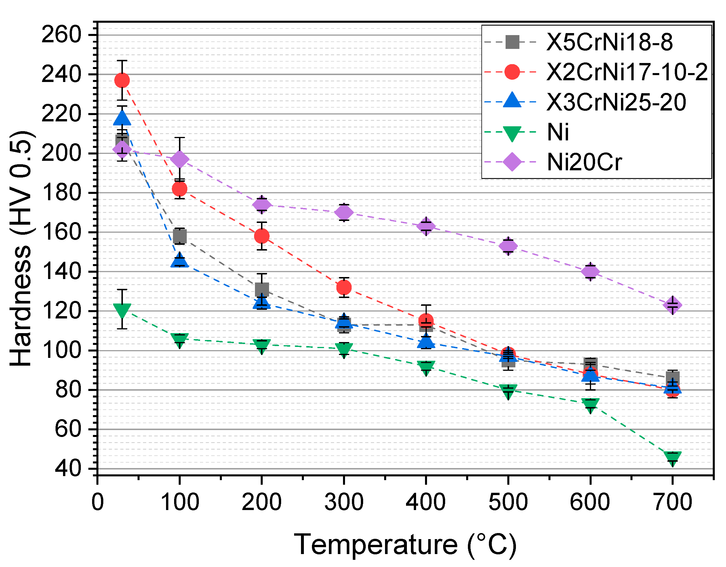
3.1. Hardness as a Function of Temperature

The hardness of a material is an indicator of its resistance against the indentation of a harder counter body, e.g., an abrasive body, representing the first stage of the abrasive wear impact. In addition, the hot hardness shows whether a material tends to unstable wear behavior at elevated temperatures. After indentation, the abrasive penetrates into the material, leading to severe abrasive wear by grooving [30]. Therefore, the ratio between the hardness of the abrasive and the base material can be used to indicate the wear rate at room temperature [31]. Particularly at high temperature, the hardness of the Al2O3 counter body exceeds the hardness of the base material within the investigated temperature range, showing the applicability of the measurement principle with an Al2O3 counter body [5,24,25].
As shown in Figure 1, the hot hardness of all materials decreases with increasing temperature. When considering Ni, it can be seen that the (hot) hardness of Ni increases significantly with the addition of 20 wt.% Cr, resulting from paraelastic solid solution strengthening [32]. Furthermore, the austenitic stainless steels showed an influence of Mo in the RT-hardness of the investigated alloys, which is limited up to 500 °C [33]. By means of high temperature hardness, no significant influence of alloy composition of the austenitic stainless steels can be pointed out. Moreover, the measured values indicate a stable hot wear behavior at elevated temperature, because no significant and not steady decrease in hot hardness can be found with rising temperature.

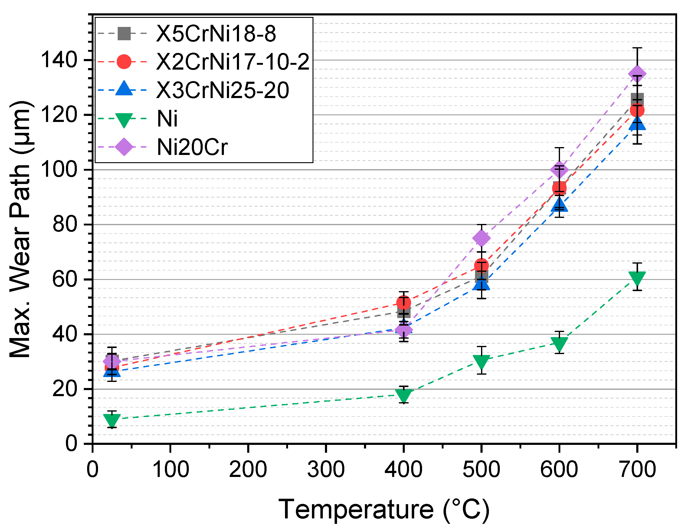
3.2. Wear Coefficients during Sliding Abrasion as a Function of Temeprature

The results of conducted sliding abrasion experiments at RT and high temperature can be seen in Figure 2 and Figure 3. These are shown as temperature dependent friction coefficients and wear path of the investigated materials. All materials show an increase in wear rates and friction coefficient with rising temperature, which results from an increasing softening and deformability of single-phase materials. This leads to a higher lateral force during the sliding motion, resulting in a higher friction coefficient [6]. At the same time, those parameters and their dependence on temperature are strongly affected by the tested base material. Lower friction coefficients can be measured in Ni and X2CrNiMo17-10-2. Furthermore, Ni has the lowest wear path of all investigated single phase fcc materials. Ni20Cr and X3CrNi25-20 show the highest friction coefficients, indicating a higher resistance against sliding abrasion. This resistance may be due to the work-hardening capability during severe plastic deformation, which is influenced by microstructural parameters [34,35,36]. In terms of friction coefficient of X5CrNi18-8, the fcc-phase stability may not be sufficient, so that noticeable amounts of α′-martensite emerge during testing because of severe deformation [5]. This phase transition leads to a considerable work-hardening of this stainless steel, measured in particular by the friction coefficient [5].
Especially, Ni shows a significant change in wear path and friction coefficient when alloyed with Cr. The reason for this behavior is the high ductility and low toughness of pure Ni. Therefore, it is almost exclusively plastically deformed and not ablated.
Scratch energies of the studied alloys can be seen in Figure 4, showing a lower scratch energy for Ni in comparison to the other investigated fcc materials. This parameter indicates the work-hardening potential of a material. Due to a high scratch energy describes, much energy is dissipated by microstructural deformation processes [37]. The combination of increased work hardening capability due to a lower SFE and the strong solid solution strengthening due to Cr increases the work required for deformation of the alloy Ni20Cr compared to pure Ni [38,39]. Scratch energy of the austenitic stainless steels resembles the scratch energy of Ni20Cr. Data shows that the austenitic steels have a breakeven point at 500 °C. This indicates that the work-hardening potential of the austenitic stainless steels is nonlinear. At 700 °C, the alloy X3CrNi25-20 has the highest scratch energy, showing that this alloy has the highest work-hardening potential, which agrees with the thermodynamic SFE calculations by Fussik et al. [14].

3.3. Microstructural Parameters at Room Temperature

Table 2 displays the measured microstructural parameters of all investigated alloys at RT. The data shows that the SFE differs for all materials with different alloy composition. The alloy X5CrNi18-8 has the lowest SFE, while X2CrNiMo17-10-2 exerts a slightly higher SFE. X3CrNi25-20 has the highest SFE of the austenitic steels at RT.
Comparing X5CrNi18-8 and X3CrNi25-20, it can be seen that the SFE of X3CrNi25-20 is significantly higher at RT. This is a result of the higher Ni amount, which increases the SFE as well as the thermodynamic stability of the fcc phase [40]. Furthermore, Ni reduces the volume fractions of α’-martensite of austenitic CrNi-steels in the CW condition [5,13]. The significantly higher SFE of pure Ni in comparison to the austenitic steels results from strong atomic bonding due to high electron density contributing to metallic bonding [29,41,42]. This correlation can be seen when the SFE values of Ni, Au, and Cu are compared. These elements differ in their specific lattice parameters, even though the electron density is the decisive parameter to determine the SFE [5,23].
Regarding Ni and Ni20Cr, the SFE can be lowered significantly by alloying Cr. The combination of an increased work hardening capability due to a lower SFE and the strong solid solution strengthening of Ni-based materials by Cr increases the work required for deformation of the alloy Ni20Cr compared to pure Ni [38,39]. This gives a direct relationship between solid solution strengthening and the SFE of a material, thus the formation and possibility of formation and hindrance of strengthening dislocation structures, and the material resistance to severe sliding abrasion (Figure 1, Figure 2, Figure 3 and Figure 4) [43]. This behavior results from the change in electron configuration due to Cr, which in turn causes a change in binding energy, due to which the formation of stacking faults (SF) is significantly simplified, which can be seen in the SFP of both materials [44].

3.4. Influence of Microstructural Parameters and Their Behavior at Elevated Temperatures

Table 3, Table 4 and Table 5 show the temperature dependent microstructural parameters SFP, microstrain and lattice parameters as well as the calculated SFE. It is noticeable that the SFE is influenced by temperature and alloy composition [45,46].
Regarding the SFP, for all materials the SFP decreases with increasing temperature, lowering the tendency to form planar faults. This parameter is lowest for Ni, while X5CrNi18-8 has a much higher SFP than X3CrNi25-20. Both stainless steels may have the same SFP at higher temperatures, indicating that the energy to form planar defects may be the same at rising temperature. This is due to the inverse effect of SFE and SFP, which is noticeable in these materials.
By considering the microstrain, a statement concerning the accumulated deformation can be made. The decrease of this parameter with rising temperature indicates the recovery process of the material and the rearrangement of the deformed structures take place. This is noticeable in all materials but more pronounced in the austenitic steels with rising temperature.
All materials show a thermal increase of the lattice parameter a0 due to thermal expansion.
The increase of the SFE with rising temperature results from an increasing SFP/microstrain ratio, which increases the SFE. As shown by Remy and Pineau [47], the SFE changes at high temperatures due to the changed spacing of partial dislocations of an SF. When measured in situ, the SFE can revert to the initial value when lowering the temperature [47]. This can be observed on all alloys.
A direct comparison of the austenitic stainless steels is shown in Figure 5. When one contrasts the austenitic stainless steels, it can be stated that X3CrNi25-20 starts with a higher SFE value, while the SFE temperature gradient is lower. This behavior shows that a RT-dependent approach cannot be extrapolated to the high-temperature SFE, confirming the concept of alloy development from Fussik et al. [14]. Especially, a Cr/Ni-ratio of 1.25 seems optimal when comparing these alloys and when considering high-temperature low-SFE [14]. Meanwhile, a rising SFE with increasing temperature is inevitable for austenitic steels due to the thermal stabilization of the fcc phase [47]. Thus, the higher SFE of X3CrNi25-20 at RT states a higher austenite stability due to that correlation. Furthermore, the deformation mechanism of a material changes due to thermal reasons, which will be concretized in the following [48].
At a temperature range of 700–1000 °C, dislocation gliding is predominantly present and dynamic recrystallisation and recovery have to be considered, which are mainly influenced by the material specific SFE [49]. Regarding this correlation, the high temperature SFE is a significant parameter when developing stainless steels for high-temperature wear applications.

3.5. Correlation of Hot Wear and Microstructural Parameters

Previous studies indicated a relationship between SFE and the resistance against severe sliding abrasion of austenitic stainless steels [5]. To work out the correlation, EBSD measurements of the deformed wear scars were carried out in order to determine the density of dislocation structures and dynamic recrystallisation to counteract thermal softening and indicate the work-hardening potential. Especially Ni and Ni20Cr are used, in order to determine the influence of SFE on the deformations mechanisms because both systems are well-known from the literature, with a well-known significantly lower SFE of Ni20Cr over the examined temperature range [4]. Figure 6 shows the wear affected subsurface microstructures of both Ni and Ni20Cr. The scans highlight that the material with the lower SFE has more pronounced dislocation structures and the area of dislocation is higher during severe plastic deformation. This indicates that the response of the material to plastic deformation by an abrasive is directly related to the SFE of the material. This behavior can be observed in a wide temperature range for Ni and Ni20Cr.
A similar behavior was also observed by Pinto [50] on CrNi steels. Figure 7 shows the wear-affected zone and the subsurface of the three austenitic steels X5CrNi18-8, X2CrNiMo17-10-2, and X3CrNi25-20. It has to be mentioned that for the materials X5CrNi18-8 and X2CrNiMo17-10-2, appreciable contents of α′-martensite occurred in the wear tests, which have already been investigated in a previous work by Walter et al. [5] and are therefore not part of this study. Nevertheless, all investigated alloys show a changing subsurface due to severe plastic deformation depending on temperature, while X3CrNi25-20 shows no formation of α′-martensite. The microstructural images of the wear tests at temperatures over 700 °C also show that in all the materials considered, there is a change in the microstructure as a result of thermally activated microstructural processes, from which recrystallized microstructural regions form independently of the base metal. There is a pronounced formation and extrusion of sliding band structures in the edge area of the wear marks.
This relationship between wear behavior and SFE becomes clear when the influence of SFE on the deformation behavior of fcc materials is investigated in more detail, since this deformation behavior in particular determines the response of a material to scratching. Thus, the reaction of SF with slip bands and other SF results in dislocation structures that are difficult to move. In particular, the formation of the crossing points of two SF (Lomer–Cottrell-dislocations) hinders the movement of dislocations very effectively [51]. This relationship explains why the materials with lower SFE react with a higher friction coefficient and a higher scratch energy (Figure 2 and Figure 4) due to higher work-hardening capability as well as a stronger dynamic recrystallization resulting from many nucleation sites for new grain formation due to the low SFE (Figure 6 and Figure 7).

4. Conclusions

This work presents the hot wear behavior as well as the microstructural parameters of three austenitic stainless steels in comparison to pure Ni and Ni20Cr. Experimental results provide the SFE as a function of temperature and analyze the correlation between SFE and wear behavior at elevated temperatures. Particularly, the deformation behavior caused by severe sliding abrasion is analyzed as a function of temperature.
  • The hot hardness tests show no instability of the mechanical properties of all fcc-materials. This is underlined by the friction coefficients and wear paths. The scratch energy shows a nonlinear correlation, with a break-even point, where the alloy X3CrNi25-20 shows a higher work-hardening potential indicated by the scratch energy than the other materials.
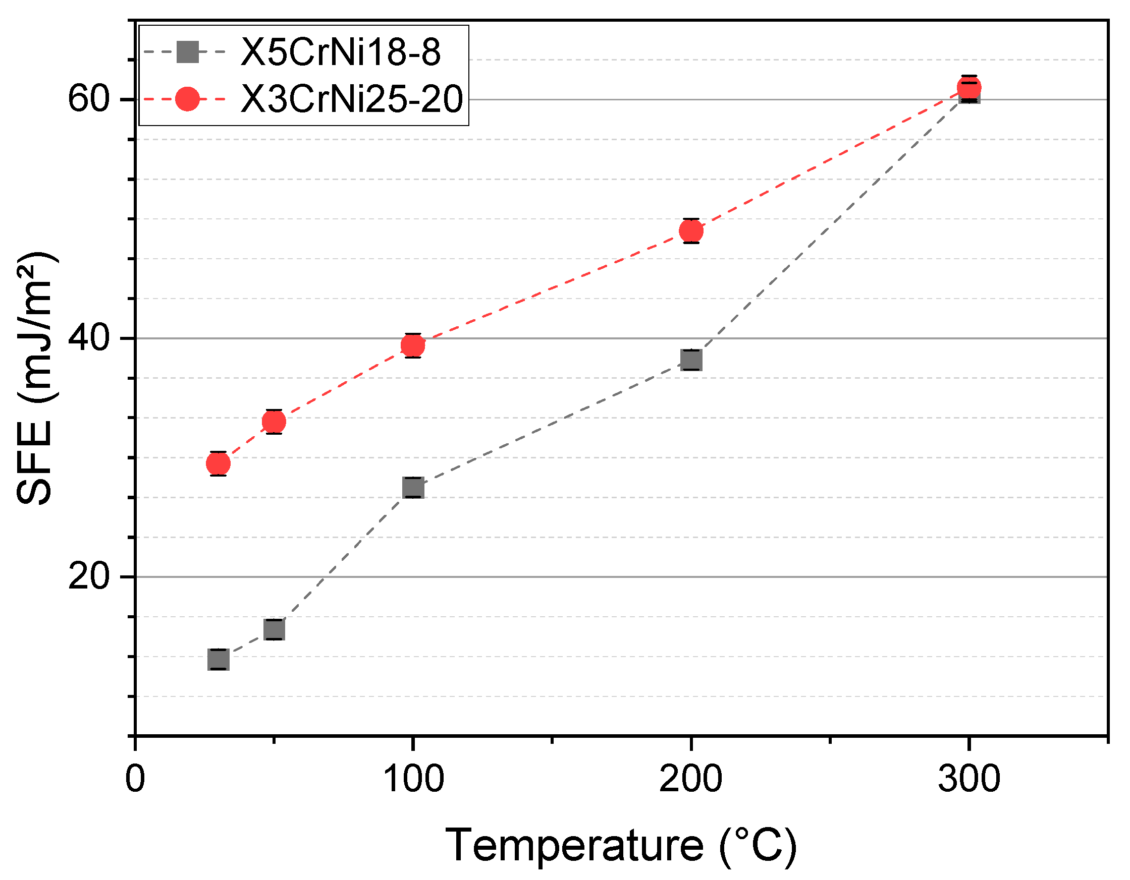
  • In situ X-ray experiments show that the SFE differs significantly with an increasing temperature. The SFE of X5CrNi18-8 and X3CrNi25-20 differ, with a higher SFE of X3CrNi25-20, while both alloys have the same SFE at 300 °C. The reason for this behavior is the CrNi-ratio, with has been identified as a relevant parameter in previous studies and is confirmed in this work.
  • The SFE of a material determines the work-hardening potential during abrasive sliding abrasion. Especially when considering Ni and Ni20Cr, it can be seen that the SFE is significantly lowered by alloying with Cr. This behavior and its impact on the hot wear behavior can be observed in the EBSD scans taken in the cross section of the wear affected area. These scans show a higher dynamic recrystallisation resulting from the lower SFE, which enables the material to build more SF who atcs as nucleation sites for new grains. Due to the higher amount of new grains, the grain size of Ni20Cr at 700 °C in the wear affected area is significantly lower, counteracting thermal softening mechanisms.

Author Contributions

Conceptualization, A.B.; methodology, A.B. and M.W.; investigation, A.B. and M.W.; Visualization, A.B.; writing—original draft preparation, A.B.; writing—review and editing, A.B., M.W., S.M.B., S.W.; formal analysis, M.W., S.M.B., S.W.; funding acquisition, S.W.; supervision, S.W. All authors have read and agreed to the published version of the manuscript.

Funding

This research was funded by Deutsche Forschungsgemeinschaft (DFG) grant number TH531/19-2.

Data Availability Statement

The raw/processed data required to reproduce these findings cannot be shared at this time as the data also forms part of an ongoing study.

Acknowledgments

The authors thank the Deutsche Forschungsgemeinschaft for the financial support provided within the project “Warmfeste austenitische Stähle als Matrixwerkstoffe für Verschleißanwendungen über 400 °C” (Project-Nr. TH531/19-2). We acknowledge support by the Open Access Publication Funds of the Ruhr-Universität Bochum.

Conflicts of Interest

The authors declare no conflict of interest.

References

  1. Heidrich, R. Strahlverschleiß Metallischer Werkstoffe. Doctoral Thesis, Dortmund Technical University, Dortmund, Germany, 1994. [Google Scholar]
  2. Chadeesingh, D.; Hayhurst, A. The combustion of a fuel-rich mixture of methane and air in a bubbling fluidised bed of silica sand at 700 °C and also with particles of Fe2O3 or Fe present. Fuel 2014, 127, 169–177. [Google Scholar] [CrossRef]
  3. Berns, H.; Fischer, A. Tribological stability of metallic materials at elevated temperatures. Wear 1993, 162–164, 441–449. [Google Scholar] [CrossRef]
  4. Walter, M. Tribologische und Mikrostrukturelle Aspekte des Abrasiven Warmverschleißes Einphasiger, Metallischer Werkstoffe. Ph.D. Thesis, Ruhr-University Bochum, Bochum, Germany, 2017. ISBN 978-3-943063-26-4. [Google Scholar]
  5. Walter, M.; Weber, S.; Boes, J.; Egels, G.; Theisen, W. Mechanisms of severe sliding abrasion of single phase steels at elevated temperatures: Influence of lattice structure and microstructural parameters. Wear 2017, 376–377, 468–483. [Google Scholar] [CrossRef]
  6. Blau, P.J. Elevated-temperature tribology of metallic materials. Tribol. Int. 2010, 43, 1203–1208. [Google Scholar] [CrossRef]
  7. Fischer, A. Einfluss der Temperatur auf das Tribologische Verhalten Metallischer Werkstoffe; VDI Verlag: Düsseldorf, Germany, 1994. [Google Scholar]
  8. Berns, H.; Koch, S. High temperature sliding abrasion of a nickel-base alloy and composite. Wear 1999, 225–229, 154–162. [Google Scholar] [CrossRef]
  9. Berns, H.; Franco, S.D. Effect of coarse hard particles on high-temperature sliding abrasion of new metal matrix composites. Wear 1997, 203–204, 608–614. [Google Scholar] [CrossRef]
  10. Berns, H.; Fischer, A.; Kleff, J. Scratch tests on iron-, nickel- and cobalt-based alloys at elevated temperatures. Wear 1993, 162–164, 585–589. [Google Scholar] [CrossRef]
  11. Dehghan-Manshadi, A.; Barnett, M.; Hodgson, P. Recrystallization in AISI 304 austenitic stainless steel during and after hot deformation. Mater. Sci. Eng. A 2008, 485, 664–672. [Google Scholar] [CrossRef]
  12. Kocks, U.; Mecking, H. Physics and phenomenology of strain hardening: The FCC case. Prog. Mater. Sci. 2003, 48, 171–273. [Google Scholar] [CrossRef]
  13. Walter, M.; Roncery, L.M.; Weber, S.; Leich, L.; Theisen, W. XRD measurement of stacking fault energy of Cr–Ni austenitic steels: Influence of temperature and alloying elements. J. Mater. Sci. 2020, 55, 13424–13437. [Google Scholar] [CrossRef]
  14. Fussik, R.; Walter, M.; Theisen, W.; Weber, S. Investigation of austenitic FeCrNi steels with regard to stacking-fault energy and thermal austenite stability. Materialia 2018, 3, 265–273. [Google Scholar] [CrossRef]
  15. Das, A. Revisiting Stacking Fault Energy of Steels. Met. Mater. Trans. A 2015, 47, 748–768. [Google Scholar] [CrossRef]
  16. Curtze, S.; Kuokkala, V.-T.; Oikari, A.; Talonen, J.; Hänninen, H. Thermodynamic modeling of the stacking fault energy of austenitic steels. Acta Mater. 2011, 59, 1068–1076. [Google Scholar] [CrossRef]
  17. Miodownik, A. The calculation of stacking fault energies in Fe Ni Cr alloys. Calphad 1978, 2, 207–226. [Google Scholar] [CrossRef]
  18. Ferreira, P.; Müllner, P. A thermodynamic model for the stacking-fault energy. Acta Mater. 1998, 46, 4479–4484. [Google Scholar] [CrossRef] [Green Version]
  19. Molnár, D.; Engberg, G.; Li, W.; Vitos, L. Deformation Properties of Austenitic Stainless Steels with Different Stacking Fault Energies. Mater. Sci. Forum 2018, 941, 190–197. [Google Scholar] [CrossRef]
  20. Schramm, R.E.; Reed, R.P. Stacking fault energies of seven commercial austenitic stainless steels. Met. Mater. Trans. A 1975, 6, 1345–1351. [Google Scholar] [CrossRef]
  21. Bampton, C.; Jones, I.; Loretto, M. Stacking fault energy measurements in some austenitic stainless steels. Acta Met. 1978, 26, 39–51. [Google Scholar] [CrossRef]
  22. Petrov, Y. On the electron structure of Mn–, Ni– and Cr–Ni–Mn austenite with different stacking fault energy. Scr. Mater. 2005, 53, 1201–1206. [Google Scholar] [CrossRef]
  23. Reed, R.P.; Schramm, R.E. Relationship between stacking-fault energy and X-ray measurements of stacking-fault probability and microstrain. J. Appl. Phys. 1974, 45, 4705–4711. [Google Scholar] [CrossRef]
  24. Berns, H.; Lührig, M. Mikrohärte bei erhöhter Temperatur prüfen. Mater. Test. 1994, 36, 223–226. [Google Scholar] [CrossRef]
  25. Klemm, H.; Nake, K.; Bales, A. Bestimmung der Warmhärte von metallischen und keramischen Hochtemperaturwerkstoffen*. HTM J. Heat Treat. Mater. 2011, 66, 269–274. [Google Scholar] [CrossRef]
  26. Rietveld, H.M. A profile refinement method for nuclear and magnetic structures. J. Appl. Crystallogr. 1969, 2, 65–71. [Google Scholar] [CrossRef]
  27. Spieß, L.; Teichert, G.; Schwarzer, R.; Behnken, H.; Genzel, C. Moderne Röntgenbeugung: Röntgendiffraktometrie für Materialwissenschaftler, Physiker und Chemiker, 2nd ed.; Viewweg+Teubnier|GWV Fachverlage GmbH: Wiesbaden, Germany, 2009. [Google Scholar]
  28. Tritt, T.M. Thermal Conductivity: Theory, Properties, and Applications; Kluwer Academic/Plenum Publishers: New York, NY, USA, 2004. [Google Scholar]
  29. Gottstein, G. Physikalische Grundlagen der Materialkunde; Springer: Berlin/Heidelberg, Germany, 2007. [Google Scholar]
  30. Pintaude, G.; Bernardes, F.; Santos, M.; Sinatora, A.; Albertin, E. Mild and severe wear of steels and cast irons in sliding abrasion. Wear 2009, 267, 19–25. [Google Scholar] [CrossRef]
  31. Zum Gahr, K.-H. Microstructure and Wear of Materials; Elsevier Science Publishers B.V.: Amsterdam, The Netherlands, 1987. [Google Scholar]
  32. Kallas, P. Indentation energy and abrasive wear of metals. Wear 1996, 198, 77–85. [Google Scholar] [CrossRef]
  33. Flinn, P. Solute hardening of close-packed solid solutions. Acta Met. 1958, 6, 631–635. [Google Scholar] [CrossRef]
  34. Talonen, J.; Hänninen, H. Formation of shear bands and strain-induced martensite during plastic deformation of metastable austenitic stainless steels. Acta Mater. 2007, 55, 6108–6118. [Google Scholar] [CrossRef]
  35. Assmus, K.; Hübner, W.; Pyzalla, A.; Pinto, H. Structure transformations in CrNi steels under tribological stressing at low temperatures. Tribotest 2006, 12, 149–159. [Google Scholar] [CrossRef]
  36. Feller, H.; Gao, B. Correlation of tribological and metal physics data: The role of stacking fault energy. Wear 1989, 132, 1–7. [Google Scholar] [CrossRef]
  37. Bingley, M.; Schnee, S. A study of the mechanisms of abrasive wear for ductile metals under wet and dry three-body conditions. Wear 2005, 258, 50–61. [Google Scholar] [CrossRef]
  38. Lührig, M. Temperaturabhängigkeit der Mikrohärte von Mischkristallen in Phasengemischen. Doctoral Thesis, Ruhr-University Bochum, Bochum, Germany, 1993. [Google Scholar]
  39. Kundu, S.; Das, S.K.; Sahoo, P. Properties of Electroless Nickel at Elevated Temperature-a Review. Procedia Eng. 2014, 97, 1698–1706. [Google Scholar] [CrossRef] [Green Version]
  40. Yonezawa, T.; Suzuki, K.; Ooki, S.; Hashimoto, A. The Effect of Chemical Composition and Heat Treatment Conditions on Stacking Fault Energy for Fe-Cr-Ni Austenitic Stainless Steel. Met. Mater. Trans. A 2013, 44, 5884–5896. [Google Scholar] [CrossRef]
  41. Sambongi, T. Stacking Fault Probabilities of Nickel-Iron Alloys. J. Phys. Soc. Jpn. 1965, 20, 1370–1374. [Google Scholar] [CrossRef]
  42. Tisone, T.C.; Sundahl, R.C.; Chin, G.Y. The stacking fault energy in noble metal alloys. Met. Mater. Trans. A 1970, 1, 1561–1567. [Google Scholar] [CrossRef]
  43. Chaudhuri, D.K.; Xie, D.; Lakshmanan, A.N. The influence of stacking fault energy on the wear resistance of nickel base alloys. Wear 1997, 209, 140–152. [Google Scholar] [CrossRef]
  44. Dorn, J.E. Thermodynamics of stackine faults in binary alloys. Acta Met. 1963, 11, 218–219. [Google Scholar] [CrossRef]
  45. Tian, S.; Zhu, X.; Wu, J.; Yu, H.; Shu, D.; Qian, B. Influence of Temperature on Stacking Fault Energy and Creep Mechanism of a Single Crystal Nickel-based Superalloy. J. Mater. Sci. Technol. 2016, 32, 790–798. [Google Scholar] [CrossRef]
  46. Mosecker, L.; Pierce, D.; Schwedt, A.; Beighmohamadi, M.; Mayer, J.; Bleck, W.; Wittig, J. Temperature effect on deformation mechanisms and mechanical properties of a high manganese C+N alloyed austenitic stainless steel. Mater. Sci. Eng. A 2015, 642, 71–83. [Google Scholar] [CrossRef]
  47. Rémy, L.; Pineau, A.; Thomas, B. Temperature dependence of stacking fault energy in close-packed metals and alloys. Mater. Sci. Eng. 1978, 36, 47–63. [Google Scholar] [CrossRef]
  48. Asghari, A.; Zarei-Hanzaki, A.; Eskandari, M. Temperature dependence of plastic deformation mechanisms in a modified transformation-twinning induced plasticity steel. Mater. Sci. Eng. A 2013, 579, 150–156. [Google Scholar] [CrossRef]
  49. Doherty, R.; Hughes, D.; Humphreys, F.; Jonas, J.; Jensen, D.J.; Kassner, M.; King, W.; McNelley, T.; McQueen, H.; Rollett, A. Current issues in recrystallization: A review. Mater. Sci. Eng. A 1997, 238, 219–274. [Google Scholar] [CrossRef] [Green Version]
  50. Pinto, H.C. Effect of Temperature and Environment on the Deformation Mechanisms of Austenitic Steels during Cryogenic Wear. Doctoral Thesis, Technical University of Berlin, Berlin, Germany, 2005. [Google Scholar]
  51. Cottrell, A.H.; Dexter, D.L. Dislocations and Plastic Flow in Crystals. Am. J. Phys. 1954, 22, 242–243. [Google Scholar] [CrossRef]
Figure 1. Temperature dependent hardness (HV 0.5) of the investigated materials.
Metals 11 02062 g001
Figure 2. Friction coefficient of the investigated materials.
Metals 11 02062 g002
Figure 3. Maximal wear path of the investigated materials.
Metals 11 02062 g003
Figure 4. Scratch energy of the investigated materials.
Metals 11 02062 g004
Figure 5. Temperature dependent stacking fault energy of X5CrNi18-8 and X3CrNi25-20.
Metals 11 02062 g005
Figure 6. EBSD analysis of the subsurface microstructure of Ni and Ni20Cr. Both materials have been affected by sliding abrasion at 30, 400, and 700 °C. The cross section after 3000 wear cycles is displayed.
Metals 11 02062 g006
Figure 7. EBSD analysis of the subsurface microstructure of the investigated austenitic steels. All materials have been affected by sliding abrasion at 30, 400, and 700 °C. The cross section after 3000 wear cycles is shown.
Metals 11 02062 g007
Table 1. Chemical composition of the investigated alloys.
AlloyCNSiMnCrNiMoFe
X5CrNi18-80.030.070.401.6517.917.980.23Bal.
X2CrNiMo17-10-20.020.050.431.6416.619.942.11Bal.
X3CrNi25-200.0325.519.5Bal.
Ni0.010.02Bal.0.05
Ni20Cr0.010.0116.87Bal.0.05
Table 2. Microstructural parameters of the investigated alloys at RT.
AlloySFP ε 50 2 111 × 10−6a0 (Å)SFE (mJ/m²)
X5CrNi18-829.49 ± 0.529.27 ± 0.423.603 ± 0.00212.70 ± 0.9
X2CrNiMo17-10-218.20 ± 0.2830.19 ± 0.293.606 ± 0.00223.10 ± 1.9
X3CrNi25-2013.40 ± 0.4030.74 ± 0.573.601 ± 0.00129.40 ± 1.1
Ni6.71 ± 0.147.42 ± 0.713.528 ± 0.007168.3 ± 0.7
Ni20Cr59.40 ± 0.0627.69 ± 0.253.544 ± 0.00271.4 ± 0.9
Table 3. Microstructural parameters of X5CrNi-18-8 resulting from high temperature X-ray diffraction line-profile analysis.
T (°C)SFP ε 50 2 111 × 10−6a0 (Å)SFE (mJ/m²)
30a29.15 ± 0.02929.29 ± 0.253.591 ± 0.00712.9 ± 0.8
30b29.16 ± 0.02929.72 ± 0.253.601 ± 0.00713.1 ± 0.8
5023.50 ± 0.02928.60 ± 0.253.602 ± 0.00715.6 ± 0.8
10012.99 ± 0.02927.81 ± 0.253.604 ± 0.00727.5 ± 0.8
2009.17 ± 0.02927.71 ± 0.253.608 ± 0.00738.2 ± 0.8
3005.22 ± 0.02924.51 ± 0.253.612 ± 0.00760.6 ± 0.8
30c29.09 ± 0.02929.41 ± 0.253.592 ± 0.00712.9 ± 0.8
Table 4. Microstructural parameters of X3CrNi-25-20 resulting from high temperature X-ray diffraction line-profile analysis.
T (°C)SFP ε 50 2 111 × 10−6a0 (Å)SFE (mJ/m²)
30a13.01 ± 0.3130.03 ± 0.393.601 ± 0.00229.5 ± 1.0
30b13.15 ± 0.3130.69 ± 0.393.602 ± 0.00230.2 ± 1.0
5011.60 ± 0.3129.70 ± 0.393.603 ± 0.00233.0 ± 1.0
1009.24 ± 0.3128.30 ± 0.393.606 ± 0.00239.4 ± 1.0
2007.30 ± 0.3127.77 ± 0.393.609 ± 0.00249.0 ± 1.0
3005.52 ± 0.3126.11 ± 0.393.611 ± 0.00261.0 ± 1.0
30c13.00 ± 0.3130.25 ± 0.393.602 ± 0.00229.8 ± 1.0
Table 5. Microstructural parameters of Ni resulting from high temperature X-ray diffraction line-profile analysis.
T (°C)SFP ε 50 2 111 × 10−6a0 (Å)SFE (mJ/m²)
30a6.68 ± 0.137.45 ± 0.253.519 ± 0.004169.5 ± 0.2
30b6.70 ± 0.137.46 ± 0.253.522 ± 0.004169.4 ± 0.2
506.49 ± 0.137.48 ± 0.253.524 ± 0.004175.2 ± 0.2
1006.03 ± 0.137.47 ± 0.253.529 ± 0.004188.9 ± 0.2
2005.60 ± 0.137.34 ± 0.253.535 ± 0.004200.3 ± 0.2
3004.23 ± 0.135.74 ± 0.253.539 ± 0.004207.2 ± 0.2
30c6.73 ± 0.137.51 ± 0.253.521 ± 0.004170.0 ± 0.2
Publisher’s Note: MDPI stays neutral with regard to jurisdictional claims in published maps and institutional affiliations.

