
Forming Process and Simulation Analysis of Helical Carbon Fiber Reinforced Aluminum Matrix Composite


Abstract
:1. Introduction
2. Materials and Methods
2.1. Removal of Surface Sizing Materials from Carbon Fibers
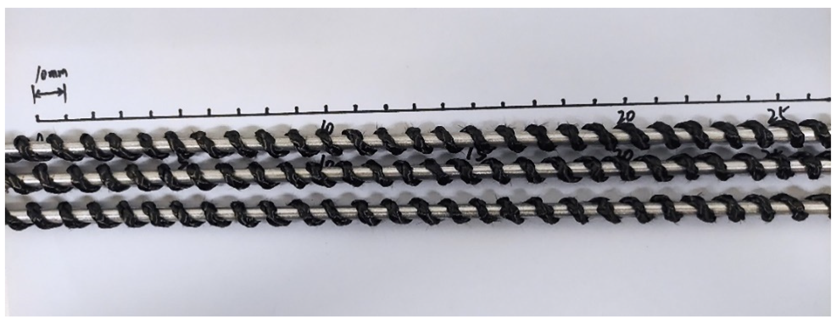
2.2. Prefabricated Part Preparation
2.3. Composite Material Preparation
2.4. Secondary Draw Forming
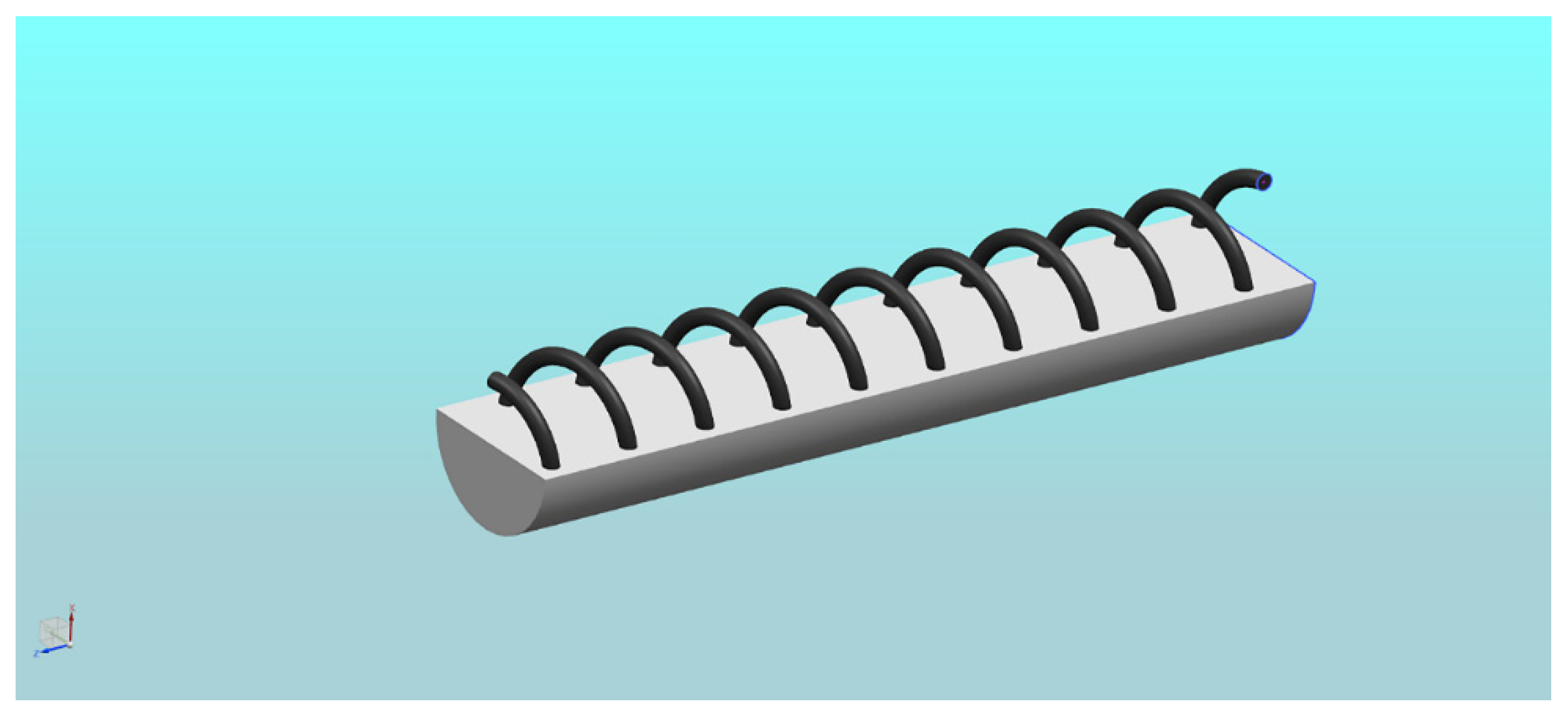
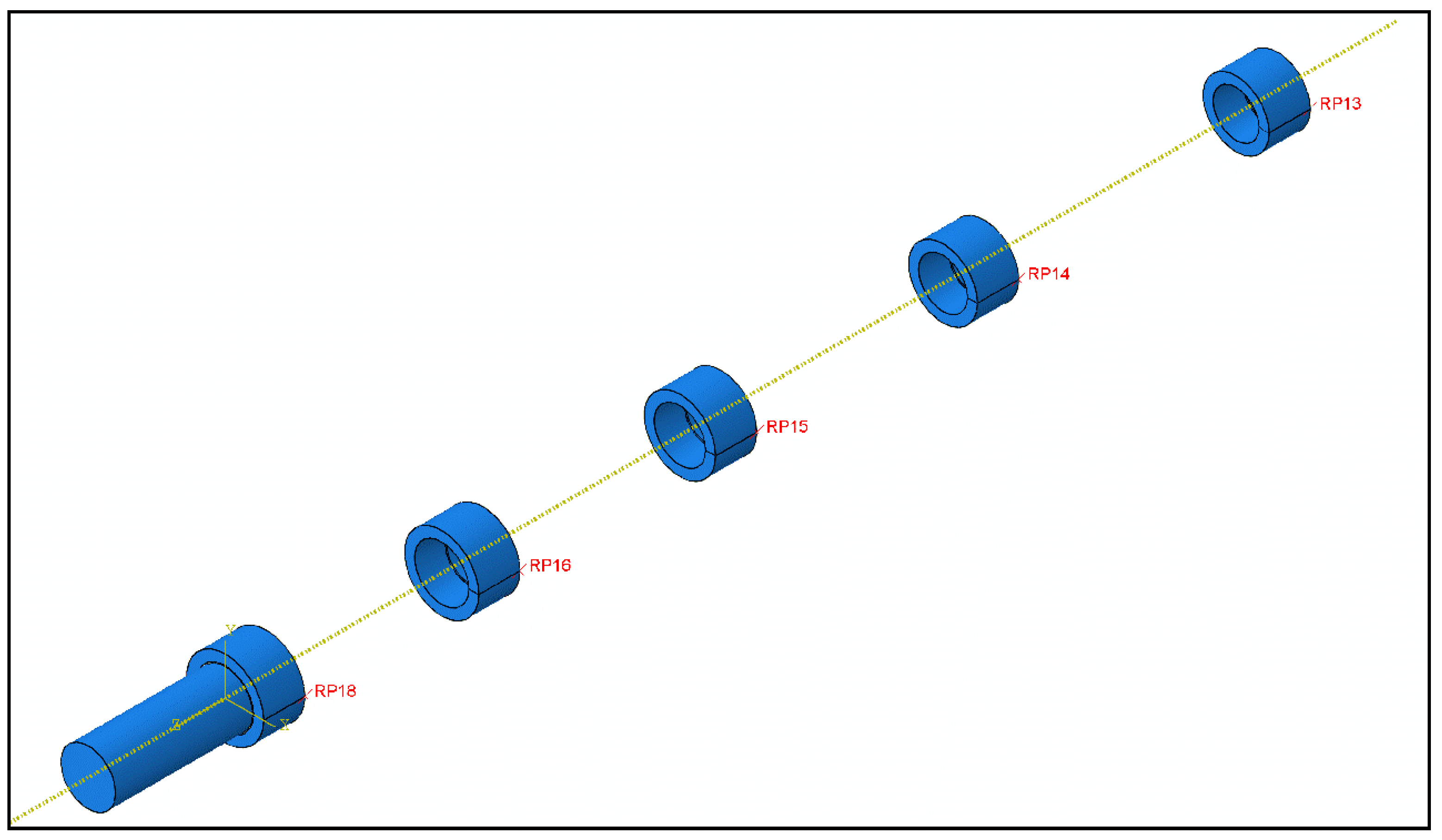
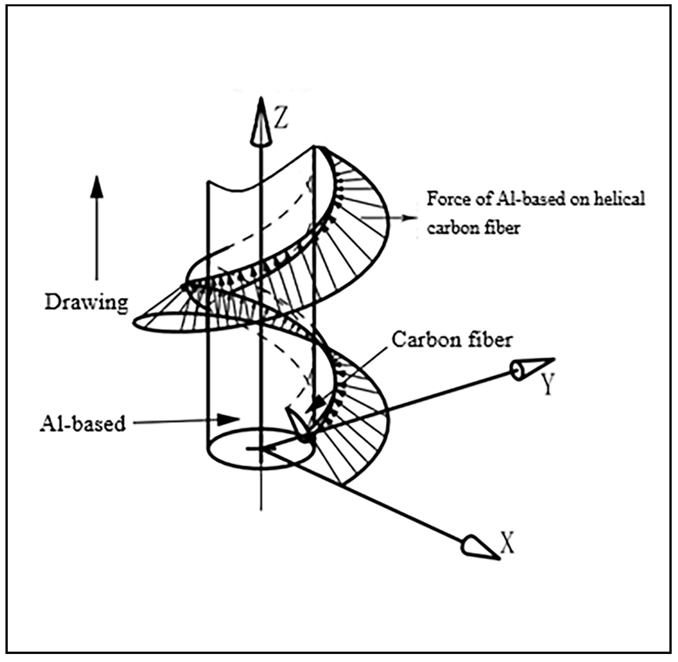
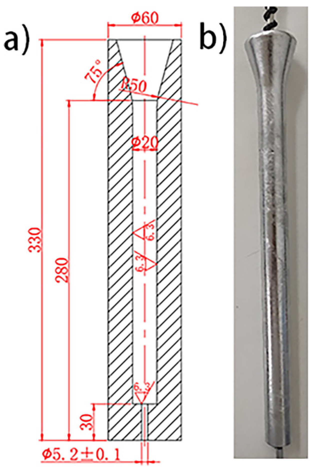
2.5. Establishment of Geometric Model
3. Results and Discussion
3.1. Numerical Simulation Results
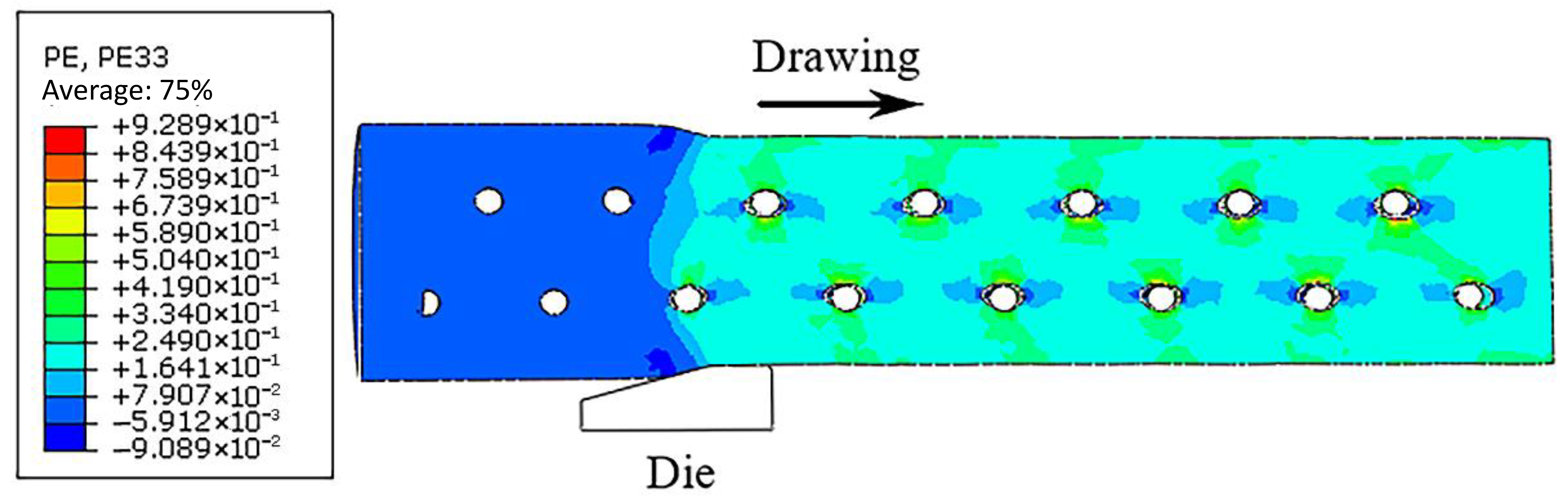
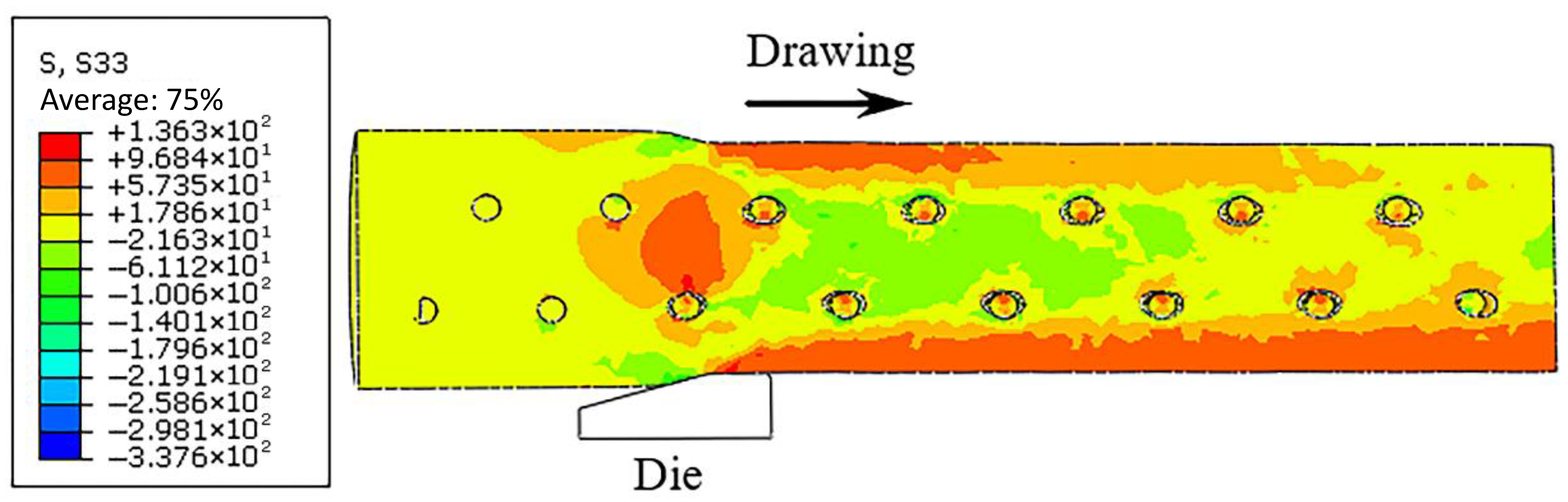
3.1.1. Analysis of Stress and Strain in the Drawing Deformation of Composite
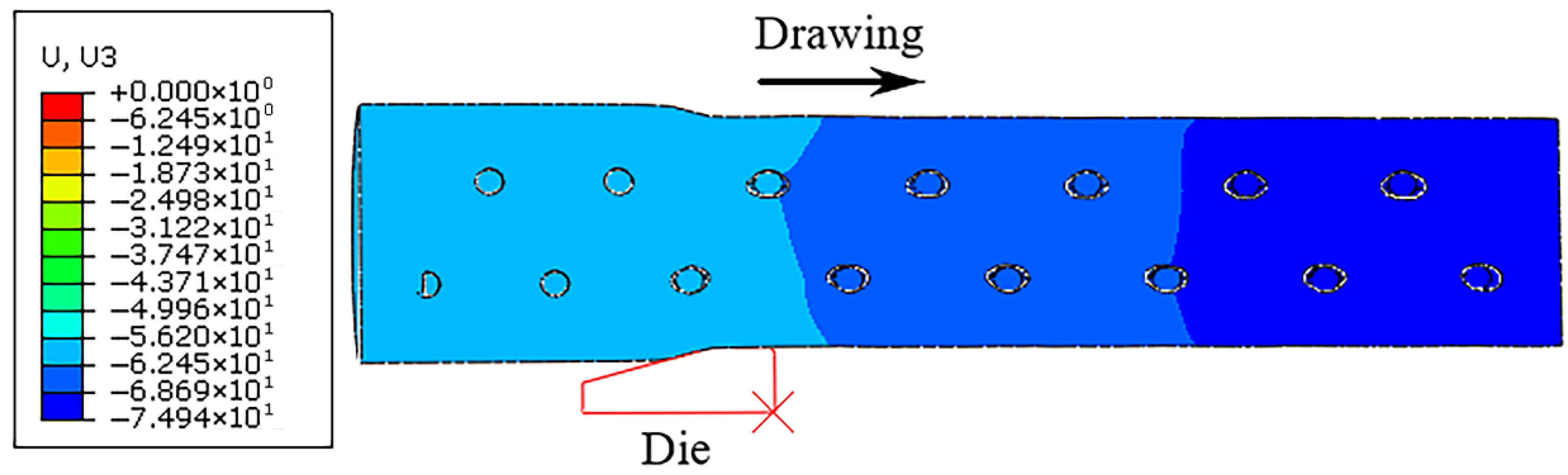
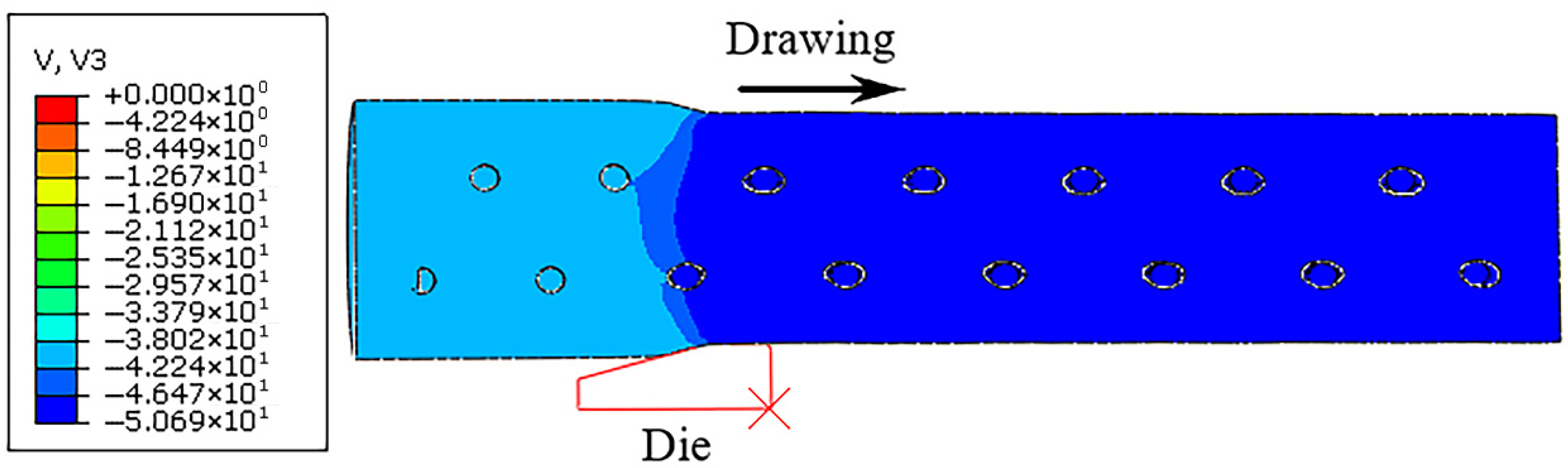
3.1.2. Analysis of Velocity and Displacement in the Drawing Deformation of Composite
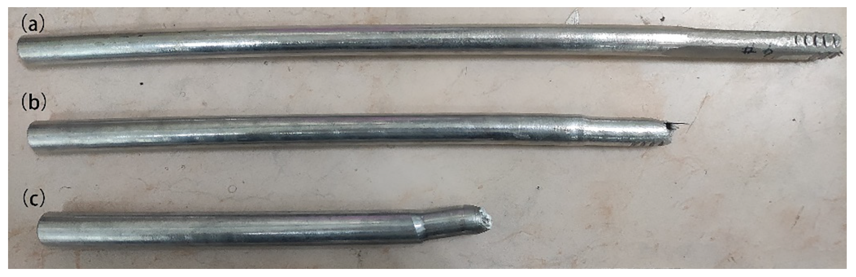
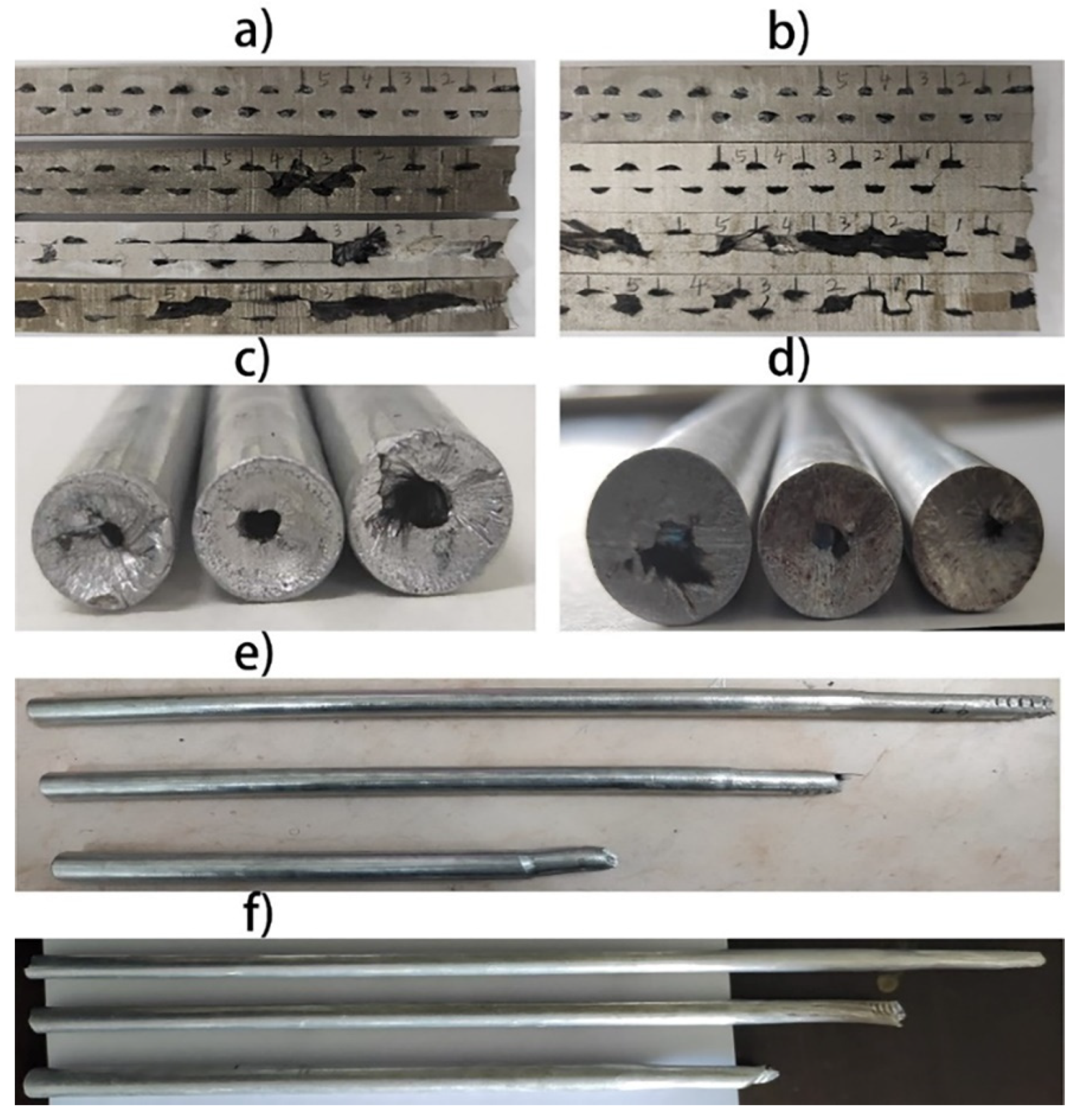
3.2. Experimental Results
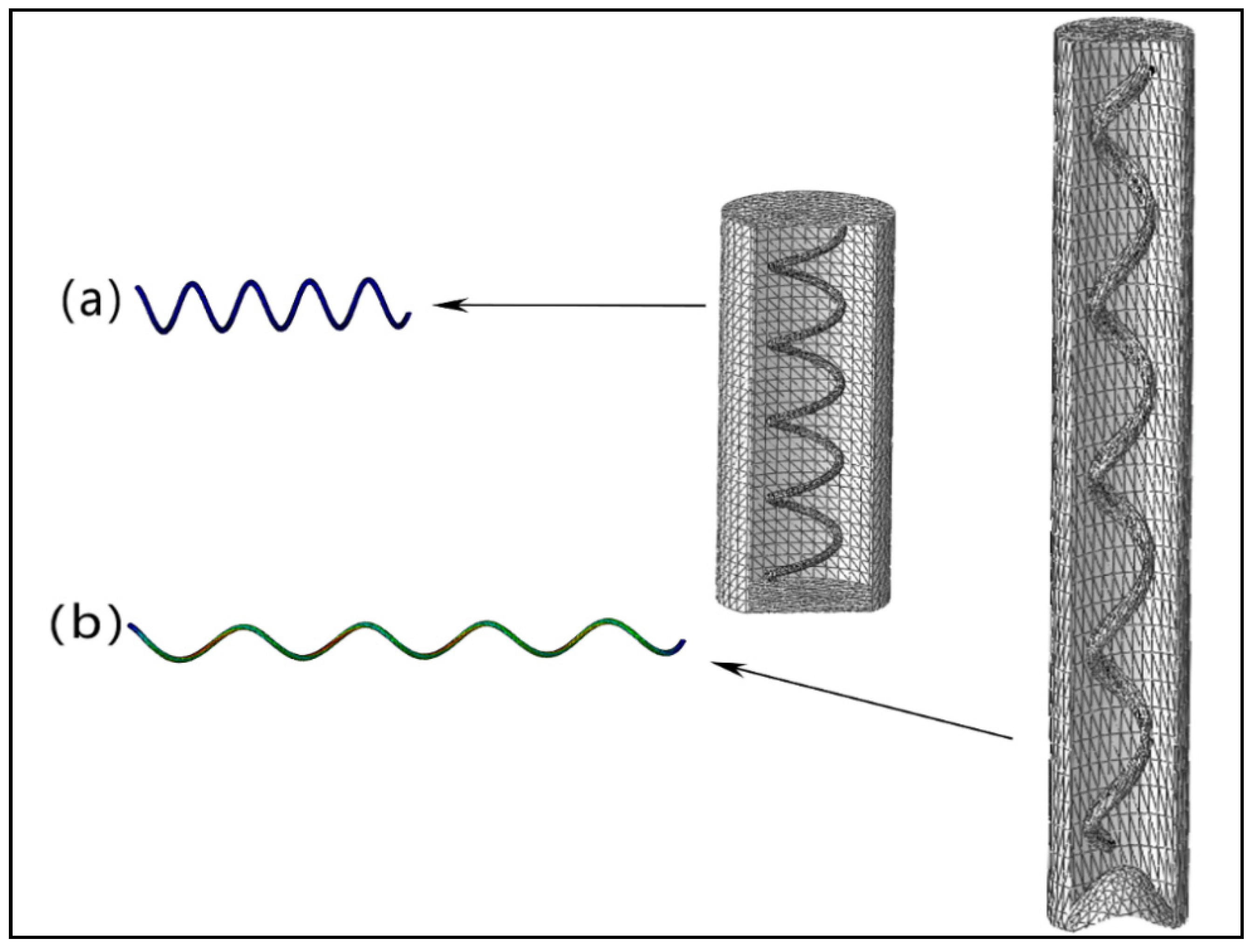
3.3. Analysis of the Deformation Pattern of Helical Carbon Fiber in Drawing
3.4. Influence of Processing Rate on Deformation of Composite
3.4.1. Effect on Deformation of Al-Based Composite
3.4.2. Effect on Helical Carbon Fiber
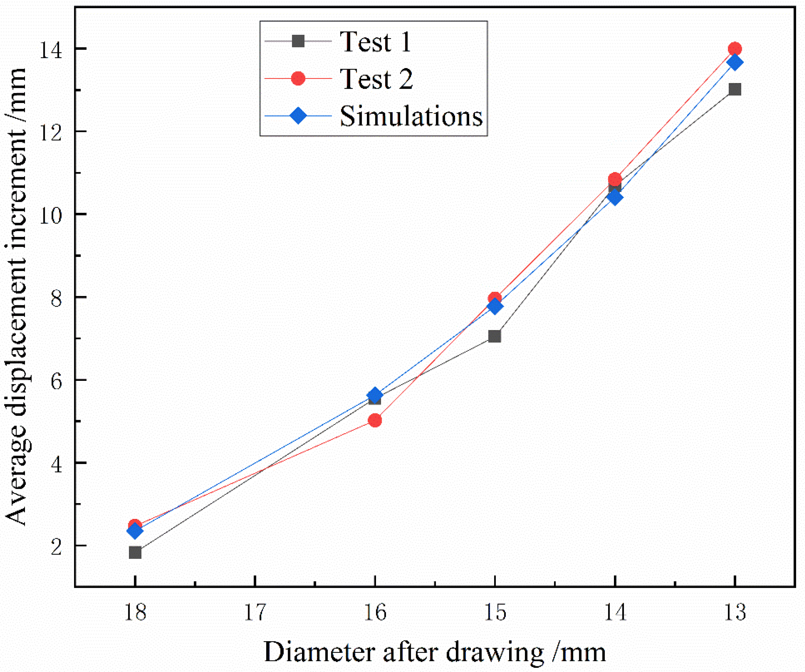
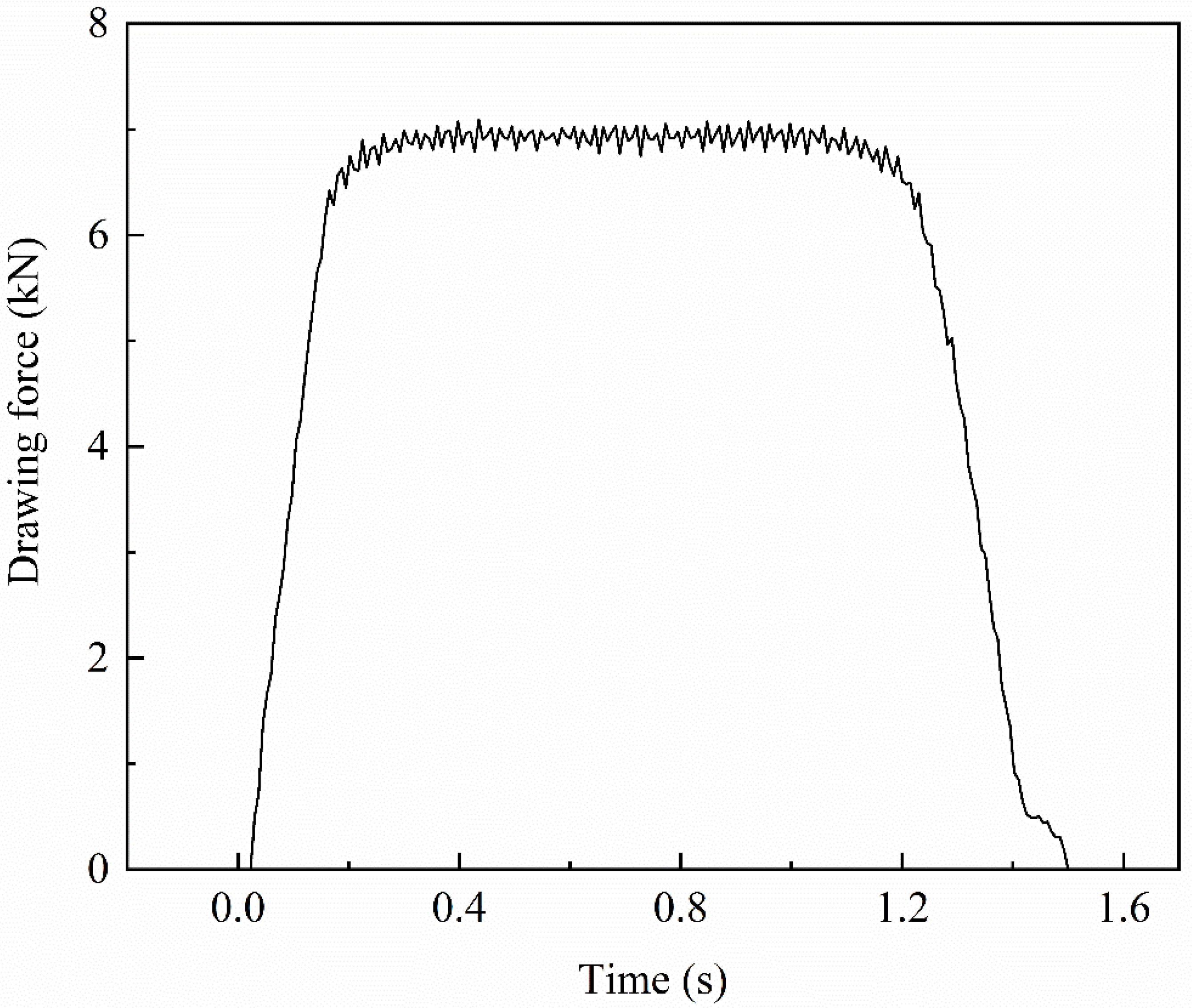
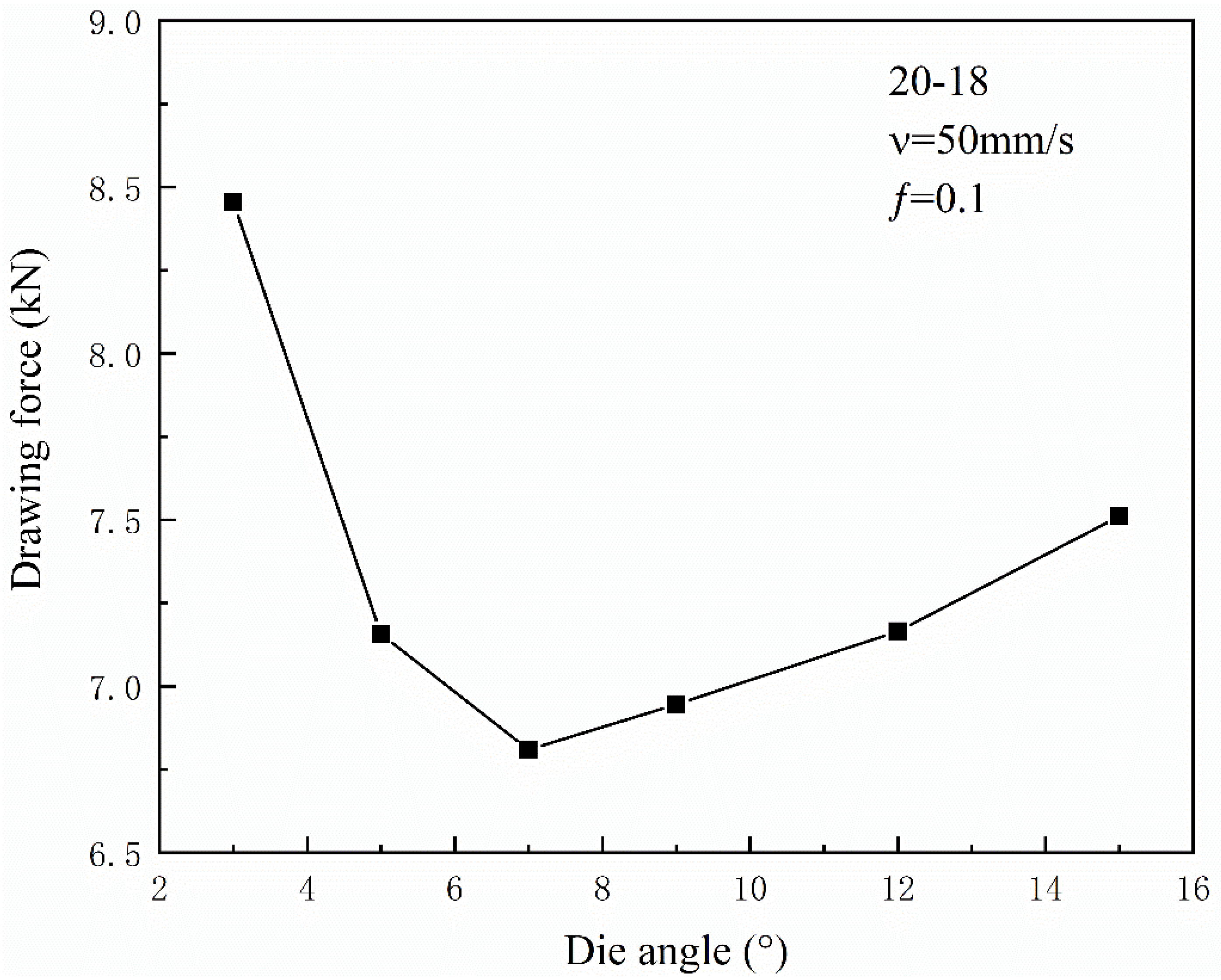
3.5. Effect of Different Drawing Parameters on Drawing Force
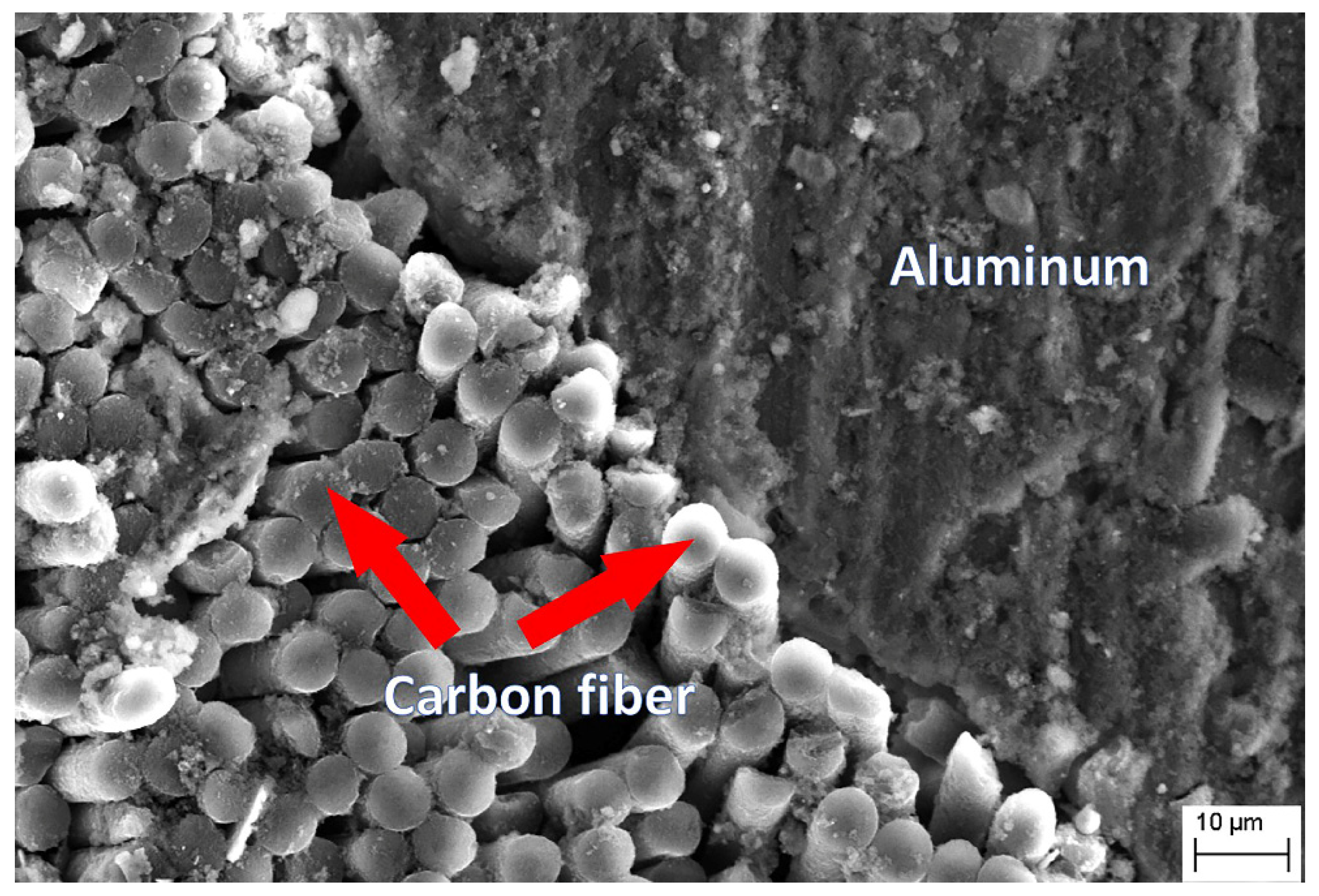
3.6. Interface of Carbon Fibers and Al-Matrix
4. Conclusions
Author Contributions
Funding
Institutional Review Board Statement
Informed Consent Statement
Data Availability Statement
Conflicts of Interest
References
- Gupta, M. Metal Matrix Composites—The Way Forward. Appl. Sci. 2020, 10, 3000. [Google Scholar] [CrossRef]
- Tang, S.; Ummethala, R.; Suryanarayana, C.; Eckert, J.; Prashanth, K.G.; Wang, Z. Additive Manufacturing of Aluminum-Based Metal Matrix Composites—A Review. Adv. Eng. Mater. 2021, 23, 2100053. [Google Scholar] [CrossRef]
- Shirvanimoghaddam, K.; Hamim, S.U.; Karbalaei Akbari, M.; Fakhrhoseini, S.M.; Khayyam, H.; Pakseresht, A.H.; Ghasali, E.; Zabet, M.; Munir, K.S.; Jia, S.; et al. Carbon fiber reinforced metal matrix composites: Fabrication processes and properties. Compos. Part A Appl. Sci. Manuf. 2017, 92, 70–96. [Google Scholar] [CrossRef]
- Miranda, A.T.; Bolzoni, L.; Barekar, N.; Huang, Y.; Shin, J.; Ko, S.; McKay, B.J. Processing, structure and thermal conductivity correlation in carbon fibre reinforced aluminium metal matrix composites. Mater. Des. 2018, 156, 329–339. [Google Scholar] [CrossRef] [Green Version]
- Davis, W.R.; Slawson, R.J.; Rigby, G.R. An unusual form of carbon. Nature 1953, 171, 756. [Google Scholar] [CrossRef]
- Chak, V.; Chattopadhyay, H.; Dora, T.L. A review on fabrication methods, reinforcements and mechanical properties of aluminum matrix composites. J. Manuf. Process. 2020, 56, 1059–1074. [Google Scholar] [CrossRef]
- Sha, J.; Lü, Z.; Sha, R.; Zu, Y.; Dai, J.; Xian, Y.; Zhang, W.; Cui, D.; Yan, C. Improved wettability and mechanical properties of metal coated carbon fiber-reinforced aluminum matrix composites by squeeze melt infiltration technique. Trans. Nonferrous Met. Soc. China 2021, 31, 317–330. [Google Scholar] [CrossRef]
- Celentano, D.J.; Palacios, M.A.; Rojas, E.L.; Cruchaga, M.A.; Artigas, A.A.; Monsalve, A.E. Simulation and experimental validation of multiple-step wire drawing processes. Finite Elem. Anal. Des. 2009, 45, 163–180. [Google Scholar] [CrossRef]
- Wang, D.H.; Ramulu, M.; Arola, D. Orthogonal cutting mechanisms of graphite epoxy composite. Part 1 unidirectional laminate. Int. J. Mach. Tools Manuf. 1995, 35, 1623–1638. [Google Scholar] [CrossRef]
- Wang, D.H.; Ramulu, M.; Arola, D. Orthogonal cutting mechanisms of graphite epoxy composite. Part 2 multi directional laminate. Int. J. Mach. Tools Manuf. 1995, 35, 1639–1648. [Google Scholar] [CrossRef]
- Rao, G.V.G.; Mahajan, P.; Bhatnagar, N. Three-dimensional macro-mechanical finite element model for machining of unidirectional-fiber reinforced polymer composites. Mater. Sci. Eng. A 2008, 498, 142–149. [Google Scholar] [CrossRef]
- Burks, B.M.; Armentrout, D.L.; Baldwin, M.; Buckley, J.; Kumosa, M. Hybrid composite rods subjected to excessive bending loads. Compos. Sci. Technol. 2009, 69, 2625–2632. [Google Scholar] [CrossRef]
- Očenášek, J.; Ripoll, M.R.; Weygand, S.M.; Riedel, H. Multi-grain finite element model for studying the wire drawing process. Comput. Mater. Sci. 2007, 39, 23–28. [Google Scholar] [CrossRef]
- Norasethasopon, S.; Yoshida, K. Finite-element simulation of inclusion size effects on copper shaped-wire drawing. Mater. Sci. Eng. A 2006, 422, 252–258. [Google Scholar] [CrossRef]
- Rauchs, G.; Thomason, P.F.; Withers, P.J. Implications of interface friction for crack growth in fibre-reinforced metal matrix composites by three-dimensional finite element modelling. Int. J. Fract. 2004, 125, 281–305. [Google Scholar] [CrossRef]
- Tang, K.K.; Li, Z.X.; Wang, J. Numerical simulation of damage evolution in multi-pass wire drawing process and its applications. Mater. Des. 2011, 32, 3299–3311. [Google Scholar] [CrossRef]
- Chang, X.; Xu, Q.; Lv, J.; Xu, L.; Zhu, Z.; Liu, S.; Liu, X.; Qin, J. Bioinspired 3D helical fibers toughened thermosetting composites. Compos. Part B Eng. 2021, 216, 108855. [Google Scholar] [CrossRef]
- Liang, J.; Wu, C.; Ping, H.; Wang, M.; Tang, W. Surface Pretreatment and Fabrication Technology of Braided Carbon Fiber Rope Aluminum Matrix Composite. Metals 2020, 10, 1212. [Google Scholar] [CrossRef]
- Junjia, Z.; Shichao, L.; Hang, C.; Yiping, L.; Qiushi, C.; Yong, D.; Tongmin, W.; Tingju, L. Surface pretreatment and fabrication technology of woven carbon fiber cloth aluminium alloy matrix composite. Mater. Sci. Forum 2015, 816, 3–8. [Google Scholar]
- Weng, L.T.; Poleunis, C.; Bertrand, P.; Carlier, V.; Sclavons, M.; Franquinet, P.; Legras, R. Sizing removal and functionalization of the carbon fiber surface studied by combined TOF SIMS and XPS. J. Adhes. Sci. Technol. 1995, 9, 859–871. [Google Scholar] [CrossRef]
- Zhang, J.; Liu, S.; Lu, Y.; Dong, Y.; Li, T. Fabrication process and bending properties of carbon fibers reinforced Al-alloy matrix composites. J. Mater. Process. Technol. 2016, 231, 366–373. [Google Scholar] [CrossRef]
- Xue, Y.; Chen, W.; Zhao, Q.; Fu, Y. Electroless carbon fibers: A new route for improving mechanical property and wettability of composites. Surf. Coat. Technol. 2019, 358, 409–415. [Google Scholar] [CrossRef]
- Hou, J.P.; Wang, Q.; Yang, H.J.; Wu, X.M.; Li, C.H.; Li, X.W.; Zhang, Z.F. Microstructure evolution and strengthening mechanisms of cold-drawn commercially pure aluminum wire. Mater. Sci. Eng. A 2015, 639, 103–106. [Google Scholar] [CrossRef]
- Alvar, E.N.; Mohandesi, J.A. Fatigue damage accumulation in cold-drawn patented steel wire under variable loading. Mater. Des. 2010, 31, 2018–2024. [Google Scholar] [CrossRef]
- Toribio, J.; González, B.; Matos, J.C. Fatigue and fracture paths in cold drawn pearlitic steel. Eng. Fract. Mech. 2010, 77, 2024–2032. [Google Scholar] [CrossRef]
- Lu, P.; Cui, F.S.; Tan, M.J. A theoretical model for the bending of a laminated beam with SMA fiber embedded layer. Compos. Struct. 2009, 90, 458–464. [Google Scholar] [CrossRef]
- Yusof, N.F.M.; Ripin, Z.M. A technique to measure surface asperities plastic deformation and wear in rolling contact. Wear 2016, 368–369, 496–504. [Google Scholar] [CrossRef]
- Biba, N.; Rezvykh, R.; Kniazkin, I.; Brabazon, D.; Naher, S.; Ahad, I.U. Coupled modelling of aluminium profiles extrusion and product quality improvement by means of simulation. AIP Conf. Proc. 2017, 1896, 140010. [Google Scholar]
- Slepyan, L.I.; Krylov, V.I.; Parnes, R. Helical inclusion in an elastic matrix. J. Mech. Phys. Solids 2000, 48, 827–865. [Google Scholar] [CrossRef]
- Zhu, Y.K.; Chen, Q.Y.; Wang, Q.; Yu, H.Y.; Li, R.; Hou, J.P.; Zhang, Z.J.; Zhang, G.P.; Zhang, Z.F. Effect of stress profile on microstructure evolution of cold-drawn commercially pure aluminum wire analyzed by finite element simulation. J. Mater. Sci. Technol. 2018, 34, 1214–1221. [Google Scholar] [CrossRef]
- Chang, C.C.; Hsieh, Y.T.; Kao, C.H.; Shao, S.Y.; Hsu, C.H. Prediction of Hardness in Drawn Copper Wire by Effective Strain from Finite Element Simulation. Mater. Sci. Forum 2019, 947, 103–108. [Google Scholar] [CrossRef]


| Specifications | Fiber Diameter/μm | Tensile Strength/GPa | Elastic Modulus/GPa | Linear Density/mg·m−1 | Bulk Density/g·cm−3 | Elongation at Break/% |
|---|---|---|---|---|---|---|
| T700 | 7 | 4.90 | 230 | 800 | 1.80 | 2.10 |
| Pass | Diameter/mm | Elongation | Area Reduction/% |
|---|---|---|---|
| 0 | 20 | 0 | 0 |
| 1st | 18 | 1.23 | 19 |
| 2nd | 16 | 1.27 | 21 |
| 3rd | 15 | 1.14 | 12 |
| 4th | 14 | 1.15 | 13 |
| 5th | 13 | 1.16 | 14 |
| Item | Parameter |
|---|---|
| Length of billet (mm) | 110 |
| Diameter of billet (mm) | 20 |
| Preheating temperature of mold (°C) | 550 |
| Total processing rate of drawing (%) | 58 |
| Drawing speed (m/min) | 3 |
| Density of Al-based (kg/m3) | 2.69 × 10³ |
| Modulus of elasticity of Al-based (GPa) | 69 |
| Poisson’s ratio of Al-based | 0.33 |
| Modulus of elasticity of carbon fiber (GPa) | E1 = 230, E2 = 20, E3 = 20 |
| Modulus of shear of carbon fiber (GPa) | G12 = 230, G13 = 20, G23 = 20 |
| Poisson’s ratio of carbon fiber | μ12 = μ13 = μ23 = 0.32 |
| Total number of Al-based lattice cells (tetrahedral cells) | 27,866 |
| Total number of carbon fiber lattice cells (hexahedral cells) | 12,309 |
| Mesh density type | Relative |
| Al-based meshing type | Sweeping meshing |
| Carbon fiber meshing type | Free meshing |
| Type of solution | ABAQUS/Explicit |
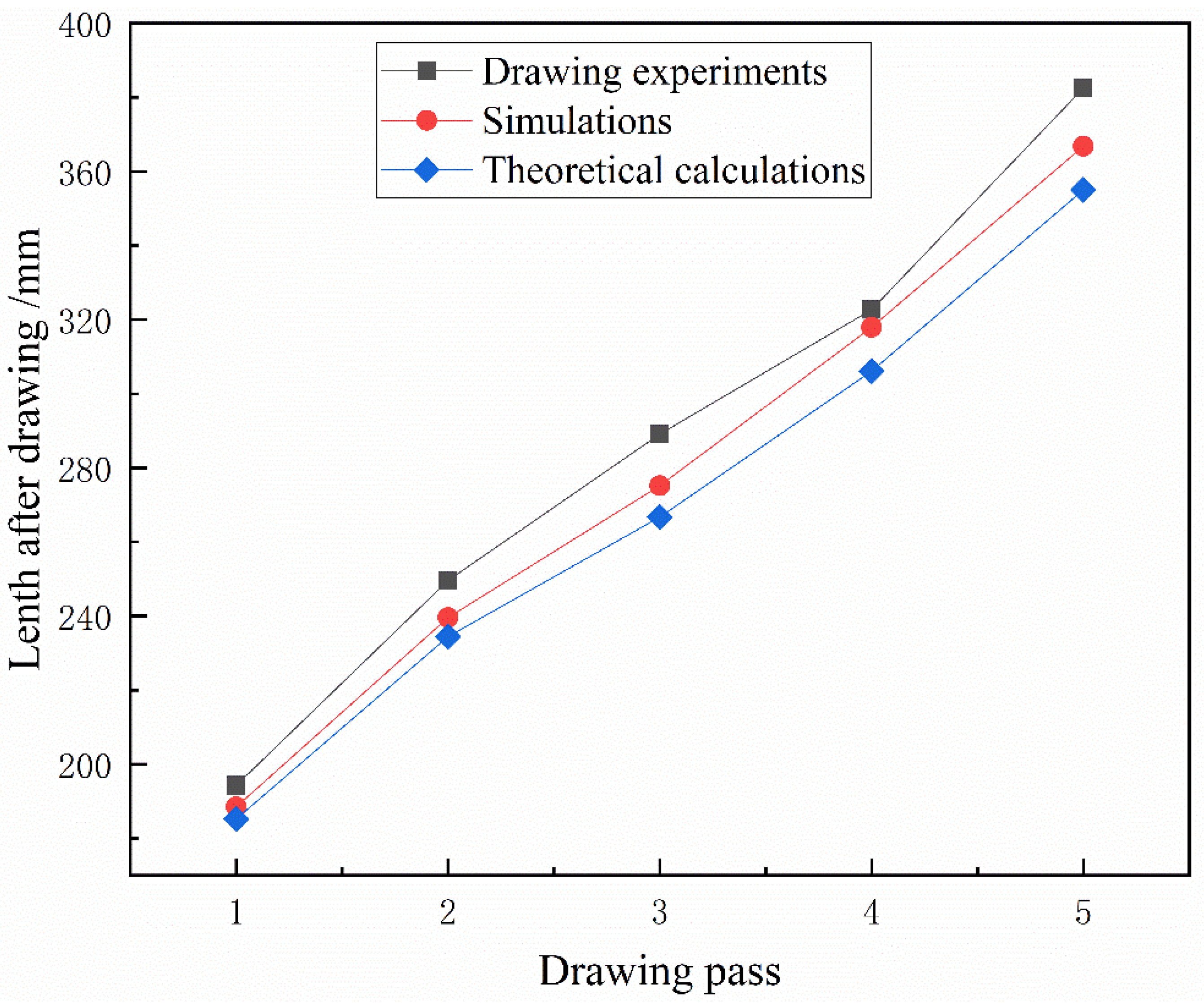
| Drawing Pass | 1st | 2nd | 3rd | 4th | 5th |
|---|---|---|---|---|---|
| Drawing experiments/mm | 194.3 | 249.6 | 289.1 | 322.7 | 382.5 |
| Simulations/mm | 188.5 | 239.6 | 275.2 | 317.9 | 366.8 |
| Theoretical calculations/mm | 185.2 | 234.4 | 266.7 | 306.1 | 355.0 |
| Group | Total Processing Rate/% | Pass Deformation/% | Die Angle/° |
|---|---|---|---|
| Test 1 | 58 (Ø20→Ø13) | 12~21 | 15 |
| Test 2 | 58 (Ø20→Ø13) | 5~6.3 | 8 |
Publisher’s Note: MDPI stays neutral with regard to jurisdictional claims in published maps and institutional affiliations. |
© 2021 by the authors. Licensee MDPI, Basel, Switzerland. This article is an open access article distributed under the terms and conditions of the Creative Commons Attribution (CC BY) license (https://creativecommons.org/licenses/by/4.0/).
Share and Cite
Liang, J.; Wu, C.; Zhao, Z.; Tang, W. Forming Process and Simulation Analysis of Helical Carbon Fiber Reinforced Aluminum Matrix Composite. Metals 2021, 11, 2024. https://doi.org/10.3390/met11122024
Liang J, Wu C, Zhao Z, Tang W. Forming Process and Simulation Analysis of Helical Carbon Fiber Reinforced Aluminum Matrix Composite. Metals. 2021; 11(12):2024. https://doi.org/10.3390/met11122024
Chicago/Turabian StyleLiang, Jun, Chunjing Wu, Zihang Zhao, and Weizhong Tang. 2021. "Forming Process and Simulation Analysis of Helical Carbon Fiber Reinforced Aluminum Matrix Composite" Metals 11, no. 12: 2024. https://doi.org/10.3390/met11122024
APA StyleLiang, J., Wu, C., Zhao, Z., & Tang, W. (2021). Forming Process and Simulation Analysis of Helical Carbon Fiber Reinforced Aluminum Matrix Composite. Metals, 11(12), 2024. https://doi.org/10.3390/met11122024