Abstract
The excellent physical and chemical properties of ultra-high temperature ceramics make them suitable for many high-temperature structural components, while their poor toughness and high sintering temperature become key limitations to their application. Laminated toughening has long been considered an effective toughening method to improve the mechanical properties of ceramics. In this study, laminated ZrB2-Mo5SiB2 ceramics with an Mo-Mo5SiB2 interlayer were fabricated by tape casting and hot press sintering at 1900 °C for 2 h. Different layer thickness ratios between the matrix layer and the interlayer were designed to illustrate the toughening mechanism. Both the fracture toughness and flexural strength of the laminated ceramics showed a trend of first increasing and then decreasing with the increase of the layer thickness ratio. High fracture toughness (9.89 ± 0.26 MPa·m1/2) and flexural strength (431.6 ± 15.1 MPa) were obtained when the layer thickness ratio was 13. The improvement in fracture toughness of the laminated ceramics could be attributed to the generation of the residual stress, the deflection and the bifurcation of the cracks. Residual stress that developed in the laminated ceramics was also evaluated.
1. Introduction
Zirconium diboride (ZrB2), one of the most promising ultra-high temperature ceramic (UHTC) materials, presents an excellent combination of physicochemical properties, such as an ultra-high melting point (3245 °C), high hardness and stiffness, a relatively low thermal expansion coefficient and density, and excellent chemical and physical stability at high temperatures [1,2,3,4,5]. These properties make the material capable of many high-temperature structural applications, including use for hypersonic vehicles, high-temperature shielding, and thermal protection systems [6,7,8,9]. However, the strong covalent bond between Zr and B results in ZrB2 ceramics with low fracture toughness and a high sintering temperature, factors which become a key limitation to their applications [10,11,12]. Once the material has microcracks due to internal stress or external force, catastrophic failure may occur, which greatly reduces the reliability of the material. Therefore, the low toughness of ZrB2 ceramics needs to be improved in order to increase reliability and safety, especially for elevated temperature conditions.
A number of studies have attempted to enhance the toughness of the composites [13,14,15,16,17,18,19,20,21,22], one of the most effective toughening methods is laminated toughening [23,24,25,26,27]. This method has achieved great effects in materials, such as SiC/TiB2, Al2O3/ZrO2, Si3N4/BN laminated composites, etc. For laminated materials, residual internal stress is generated due to the difference of the thermal expansion coefficient of the critical layer, the change of layer number and layer thickness ratio, or phase transformation. The stress acts at the crack tip to arrest crack propagation, achieving the strengthening and toughening of the materials.
In the past decade, ZrB2 based laminated ceramics have been extensively studied. Zhang et al. [28] have prepared ZrB2/SiC composites with a strong laminated structure by taking advantage of the differences in physical properties of the different layers. As such, the fracture toughness of the sample reached 7.03 MPa·m1/2. Wang et al. [29] have fabricated laminated ZrB2/Mo composites with a relatively high fracture toughness (7.52 ± 0.12 MPa∙m1/2) and high bending strength (451 ± 20 MPa) by introducing 6% Si and 4% B in the interlayers.
Mo5SiB2 can be synthesized by adding an appropriate amount of Si and B to Mo, which has a high melting point (2160 °C), good capability of anti-oxidation, and excellent high-temperature strength [30,31,32,33,34]. So far, a few studies have explored the performance of ZrB2-MoSi2 ceramics [35], but there are almost no papers devoted to the research of ZrB2-Mo5SiB2 ceramics. Mo has a high melting point (2620 °C), low thermal expansion coefficient (5.2×10⁻⁶ K−1), and excellent thermal shock resistance. These properties of Mo are close to ZrB2, which prevent ceramic cracking due to the mismatch of thermal expansion coefficient and other parameters [36]. In addition, it was reported that better performance could be obtained after dispersing Mo5SiB2 into Mo [37]. K.Yoshimi et al. [38] produced Mo-Mo5SiB2 in situ composites, and the results showed that the composites had excellent high-temperature mechanical properties and oxidation resistance when the Mo volume fraction was 34%. Therefore, 70 wt.% Mo-30 wt.% Mo5SiB2 (that is 66 vol.% Mo-34 vol.% Mo5SiB2) was selected as the interlayer in this work.
The main objective of the present research was to fabricate laminated ZrB2-Mo5SiB2 ceramics with high toughness. Herein, the laminated ceramics with ZrB2-Mo5SiB2 as the matrix layer and Mo-Mo5SiB2 as the interlayer were prepared by tape casting and hot press sintering. The microstructure and mechanical properties of the laminated ceramics, such as fracture toughness and flexure strength, were characterized. The effect of the residual stress between the matrix layer and the interlayer was also discussed and analyzed in detail.
2. Materials and Methods
Commercial ZrB2 powder (1–5 μm, 99.5%), Mo powder (0.5 μm, 99.0%), Si powder (0.5 μm, 99.0%), and B powder (1–5 μm, 99.5%) supplied by Zhongnuo New Material Technology Co., Ltd. were used as raw materials. Polyethylene glycol (PEG), Polyvinyl butyral (PVB), and Tricresyl phosphate (TCP) provided by Shanghai Macklin Biochemical Co. were chosen as the dispersant, binder, and plasticizer, respectively. In order to improve the fracture toughness of ZrB2-based ceramics, laminated ZrB2-Mo5SiB2 ceramics with Mo-Mo5SiB2 interlayer were designed based on the “brick-and-mortar” of the nacre. ZrB2-Mo5SiB2 was used as “brick” material and Mo-Mo5SiB2 was used as “mortar” material, respectively. There were two composites as matrix layers: 80 wt.% ZrB2-20 wt.% Mo5SiB2 (termed ZM20) and 70 wt.% ZrB2-30 wt.% Mo5SiB2 (termed ZM30). There was one composite as an interlayer: 70 wt.% Mo-30 wt.% Mo5SiB2 (termed IL). The layer thickness ratio (λ) was the thickness of the matrix layer to the thickness of the interlayer. There were five different ratios (λ = 7, 10, 13, 16, 19) in this work. The schematic illustration of the designed laminated ceramics is shown in Figure 1.
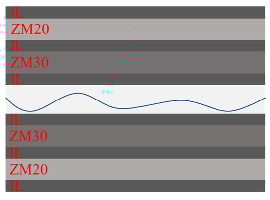
Figure 1.
Schematic illustration of the designed laminated ceramics: ZM20 (80 wt.%ZrB2-20 wt.%Mo5SiB2), IL (70 wt.% Mo-30 wt.%Mo5SiB2), ZM30 (70 wt.%ZrB2-30 wt.%Mo5SiB2).
The fabrication process of the laminated ceramics is schematically illustrated in Figure 2. The preparation procedure could be summarized in the following steps: (a) synthesis of Mo5SiB2, (b) preparation of the slurries of the matrix layer and the interlayer, (c) tape casting the slurry of the matrix layer and cut into wafers, (d) brushing the interlayer slurry onto the matrix layer wafer according to the design of the layer thickness ratio, (e) packing the stacked layers into a graphite die in an alternated sequence, (f) burning out the organic matter of materials and hot pressing.
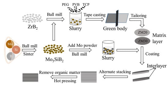
Figure 2.
Flow chart for fabrication of the laminated ceramics.
For the synthesis of Mo5SiB2, the molar ratio of Mo: Si: B powder was 5:1:2. After ball milling, the mixed powder was sintered at 10 °C/min to 1000 °C and at 5 °C/min to 1450 °C for 2 h in an argon atmosphere. Afterwards, the two matrix compounds (80 wt.% ZrB2-20 wt.% Mo5SiB2 and 70 wt.% ZrB2-30 wt.% Mo5SiB2) and the interlayer compounds (70 wt.%Mo-30 wt.%Mo5SiB2) were separately ball-milled in a planetary ball mill at 300 r/min for 6 h. The ethanol and zirconia balls were used as the solvent and the grinding medium, respectively. The weight ratio of the powder to the grinding balls was 1 to 3. The uniformly dispersed powder was obtained after rotating evaporation and sieving. In order to obtain the uniform slurry, the obtained powders were firstly dissolved in alcohol, then mechanically stirred for 3 h with the addition of 0.2 wt.% PEG, and finally, mechanically stirred for 4 h after adding 4 wt.% PVB and 4 wt.% TCP in sequence. The amount of alcohol was approximately 22 wt.%. After tape casting, the green tape of the matrix layer was obtained and cut into pieces with Φ30 mm. According to the design of the layer thickness ratio (λ = 7, 10, 13, 16, 19), the slurry of the interlayer was brushed on the pieces of the matrix layer. Then the matrix layer and the interlayer were stacked alternately into graphite die, as shown in Figure 1. In order to remove the organic matter in the material, the temperature was increased to 400 °C at a rate of 0.5 °C/min in air and kept for 8 h. The hot pressing was performed at 1900 °C and 30 MPa for 2 h in an Ar atmosphere.
The laminated ceramics were cut into bars and ground for the subsequent tests. Each specimen was polished with a diamond grinding disc. Flexural strength was tested via three-point bending on 2 mm × 3 mm × 16 mm bars, using a span of 10 mm and a crosshead speed of 0.5 mm/min by a Universal mechanical testing machine (WD-P4504, Jinan Test Machine Co., Ltd., Shenzhen, China). Fracture toughness was evaluated by a single edge notched beam (SENB) test with a span of 16 mm and a crosshead speed of 0.05 mm/min, using 2 mm × 4 mm ×22 mm bars with pre-fabricated cracks of 0.2 mm wide and 2 mm deep by a Universal mechanical testing machine. Microstructures of the laminated ceramics were observed by scanning electron microscopy (JSM-7500F, Japan Electron Optics Laboratory Co., Ltd., Tokyo, Japan). Phase constituents of the synthesized powder and the laminated ceramics were identified by X-ray diffraction analysis (XRD, PANalytical EMPYREAN, Amsterdam, the Netherlands).
3. Results
3.1. Synthesis of Mo5SiB2 Powders
The XRD pattern of the obtained Mo5SiB2 powder is shown in Figure 3. According to Figure 3, pure Mo5SiB2 was successfully synthesized after sintering at 1450 °C for 2 h in an argon atmosphere. Mo5SiB2 is the most thermodynamically stable intermetallic compound in the entire Mo-Si-B system. The phase region of Mo5SiB2 is extremely narrow, which also causes the slow diffusion of atoms in the Mo5SiB2 [39]. The impurities, such as Mo3Si and Mo2C, are easily formed at a low sintering rate. Therefore, the synthesis temperature of Mo5SiB2 should be reached as soon as possible during the heating process to avoid the formation of some impurities at lower temperatures.
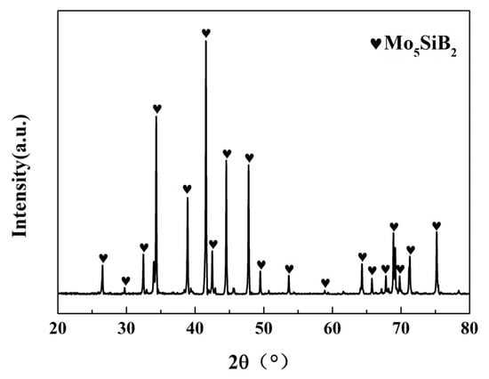
Figure 3.
XRD pattern of the obtained Mo5SiB2 powder.
3.2. Phase and Microstructure
Figure 4 show the XRD patterns of the planes parallel to the interface (P∥) and perpendicular to the interface (P⊥) in the laminated ceramics. According to the results, the main phases of both samples were ZrB2, Mo5SiB2, and Mo. Moreover, MoB was also detected. The presence of MoB may be caused by the reaction between Mo in the interlayer and ZrB2 in the matrix layer, which was beneficial to improve the bonding strength between the different layers.
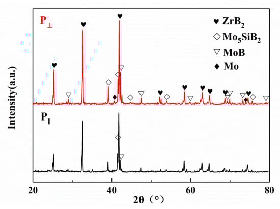
Figure 4.
XRD patterns of the planes parallel to the interface (P∥) and perpendicular to the interface (P⊥) in the laminated ceramics.
SEM micrographs of the polished cross-section of the laminated ceramics with different layer thickness ratios are provided in Figure 5. From the scanned images, it can be clearly seen that the matrix layers and the interlayers were alternately arranged and the thickness of the layers was uniformly distributed. The interface between the different layers was neat and distinct. The ZrB2-Mo5SiB2 matrix layers were dark and thick, and the Mo-Mo5SiB2 interlayers were light and thin. After debinding and sintering, the thicknesses of the matrix layer were reduced from 300 μm to 150 μm. With different thickness ratios between the matrix layer and the interlayer, the thicknesses of the interlayers were also reduced to 21.0 μm, 15.0 μm, 11.5 μm, 9.5 μm, and 8.0 μm, respectively.
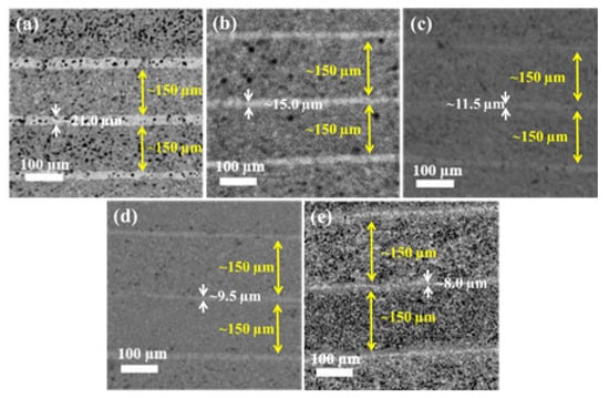
Figure 5.
SEM images of the laminated ceramics with different layer thickness ratios: (a) λ = 7, (b) λ = 10, (c) λ = 13, (d) λ = 16, (e) λ = 19.
In order to illustrate the toughening mechanism, the crack propagation paths in the laminated ceramics with different thickness ratios were observed in Figure 6. The compositions of the two matrix layers adjacent to the Mo-Mo5SiB2 interlayers (IL) were 80wt.%ZrB2-20wt.% Mo5SiB2 (ZM20) and 70wt.%ZrB2-30wt.% Mo5SiB2 (ZM30), respectively. The darker layer in the matrix layer was the ZM30 layer and the brighter layer was the ZM20 layer. As shown in Figure 6a,e, the crack propagation paths in the laminated ceramics with the layer thickness ratios of 7 and 19 presented a typically brittle fracture process, where the curves were flat without obvious deflection. As shown in Figure 6b,d, the cracks in the laminated ceramics with the layer thickness ratios of 10 and 16 exhibited multiple inflections inside the matrix layer and at the interface layer, resulting in an elongated crack propagation path. As shown in Figure 6c, the crack in the laminated ceramic with the layer thickness ratios of 13 deflected at the interface, extended laterally for a certain distance, and then extended to the next layer, forming a stepped crack appearance. The step-like cracks microstructure effectively increased the length of the crack, absorbed more fracture energy, and achieved the effect of toughening. The delamination crack at the interface was probably caused by the shear stress due to the difference of residual stress between the matrix layer and the interlayer. The phenomenon of crack deflection also existed in the matrix layer, which was also probably caused by the residual stress due to the thermal mismatch between ZrB2 and Mo5SiB2.
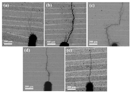
Figure 6.
SEM images of the crack propagation paths in the laminated ceramics with different layer thickness ratios: (a) λ = 7, (b) λ = 10, (c) λ = 13, (d) λ = 16, (e) λ = 19.
According to the crack propagation paths in the laminated ceramics shown in Figure 6, it could be found that the laminated ceramic with a layer thickness ratio of 13 had the best performance. Figure 7 show SEM images of the overall cross-section (a),the selected area including the matrix layer and the interlayer (b) and higher magnification of the selected area (c) of the laminated ceramic with the layer thickness ratio of 13. The laminated structure was observed in Figure 7a. As shown in Figure 7b, there were the ZM30 layer, the interlayer, and the ZM20 layer from top to bottom in the enlarged view of the laminated structure. According to the higher magnification image shown in Figure 7c, the fracture mode of the laminated ceramic was a mixture of transgranular fracture and intergranular fracture. Moreover, the matrix layer and the interlayer were tightly bonded because of the reaction of Mo and ZrB2 at the interface.
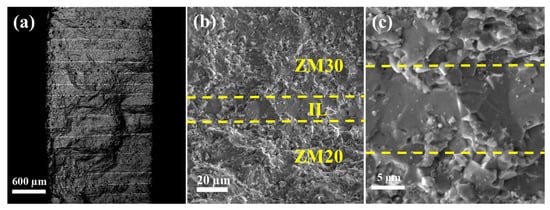
Figure 7.
SEM images of the overall cross-section (a) the selected area including the matrix layer and the interlayer (b) and higher magnification of the selected area (c) of the laminated ceramic with the layer thickness ratio of 13.
3.3. Mechanical Properties and Residual Stress
The mechanical properties of the laminated ceramics with different layer thickness ratios are shown in Table 1. As shown, the flexural strength of the laminated ceramics with layer thickness ratios of 7, 10, 13, 16, and 19 were 360.4 ± 35.3 MPa, 375.2 ± 16.1 MPa, 431.6 ± 15.1 MPa, 366.7 ± 28.0 MPa, and 351.7 ± 26.9 MPa, as well as the fracture toughness were 5.54 ± 0.40 MPa·m1/2, 6.94 ± 0.30 MPa·m1/2, 9.89 ± 0.26 MPa·m1/2, 7.06 ± 0.38 MPa·m1/2, and 6.03 ± 0.51 MPa·m1/2, respectively. Both flexural strength and fracture toughness exhibited a tendency of first increasing and then decreasing with the increase of the layer thickness ratio. Among them, the laminated ceramic with a layer thickness ratio of 13 had the highest flexural strength (431.6 ± 15.1 MPa) and fracture toughness (9.89 ± 0.26 MPa·m1/2), which was consistent with the characteristics of the crack propagation paths shown in Figure 6e.

Table 1.
Flexural strength and fracture toughness of the laminated ceramics with different layer thickness ratios.
The crack propagation path in the laminated ceramic was strong evidence for analyzing the failure mechanism of the materials. Furthermore, the crack propagation resistance was impacted by the generation of residual stresses due to the difference in thermal expansion coefficients (CTE) between the matrix layer and the interlayer. Therefore, the residual stress affected the crack propagation direction in the laminated ceramics. In order to prevent excessive internal residual stress from causing block cracking, the design of the laminated structure should take into account the difference in CTEs of the matrix layer and the interlayer. The CTEs, elastic modulus, and Poisson’s ratio of the composites can be calculated by the following Equations (1)–(3) [40]:
where E, α, υ, V are the elastic modulus, thermal expansion coefficient, Poisson’s ratio and volume fraction, respectively. Table 2 show the elastic modulus, Poisson’s ratio, and CTE of ZrB2, Mo5SiB2, Mo, two kinds of matrix layers, and the interlayers. It can be found that the CTE of the two matrix layers was larger than the interlayer. Therefore, the matrix layer was subjected to residual tensile stress, and the interlayer was subjected to residual compressive stress, as shown in Figure 8. The residual stress can be calculated by the following Equations (4) and (5) [41]:
where σ, υ, n, h, and ΔT are the residual stress, Poisson’s ratio, number of layers, layer thickness, and temperature change, respectively. The subscripts 1 and 2 represent the interlayer and matrix layer, respectively. According to the experiment process, the value of the number of layers was set as 19. From Figure 5, the layer thickness of the interlayer was 21.0 μm, 15.0 μm, 11.5 μm, 9.5 μm, and 8.0 μm, respectively. The value of ΔT was calculated from sintering temperature to room temperature, namely, 1900 °C − 25 °C = 1575 °C = 2148.15 K. h2 was 150 µm, and h1 was the thickness of the interlayer. The calculated value of the tensile stress and compressive stress of the laminated ceramics with different layer thickness ratios are shown in Table 3.
Table 2.
Elastic modulus, Poisson’s ratio, and CTEs of raw materials and the laminated ceramics.
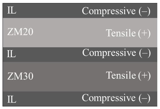
Figure 8.
Diagram of the residual stresses applied to various layers in laminated ceramics.
Table 3.
Residual stress in laminated ceramics with different layer thickness ratios.
As indicated in Table 3, as the layer thickness ratio increased, the residual compressive stress of the interlayer gradually increased from 203.15 MPa to 223.15 MPa, the residual tensile stress of the matrix layer decreased from 35.11 MPa to 11.57 MPa. According to Table 1, the laminated ceramic with a layer thickness ratio of 13 showed the highest flexure strength and fracture toughness. However, its residual compressive stress and the tensile stresses were 218.19 MPa and 17.41 MPa, respectively.
For laminated materials, residual compressive stress was beneficial for improving their mechanical properties and could keep them stable by shielding the applied stress at the crack tip [42,43]. Based on this theory, the surface of the laminated ceramics was designed as a compressive stress layer, which was useful for the improvement of flexural strength. However, the theoretical calculation and analysis of comparative performance revealed that the sample with the maximum residual compressive stress did not have the highest toughness. Since the maximum shielding effect was obtained at a distance equal to the thickness of the compressive layer from the notch tip, the thickness also played an important role. Therefore, the value of fracture toughness was influenced not only by the internal residual stress but also by the position of the notch tip and its distance from the interface. Zhang et al. [28] have also demonstrated this statement. In the case where the notch tip was located in the compressive layer, the crack would deflect at the tip. However, the crack would propagate straight through the layer when the notch tip lay in the tensile layer. Furthermore, the crack would continue to deflect as soon as it propagated to the next compressive layer. The notch depth in this experiment was uniformly set to half the thickness of the samples, and the notches were all located in the tensile layer because the compressive interface layer was so thin.
Within a certain range, such changes in internal residual stress were advantageous for the improvement of the mechanical properties. A possible explanation was that the mutual restraint of the laminated ceramics was primarily achieved through the shear stress between the matrix layer and the interlayer. When the layer thickness ratio increased, the reduction in the thickness of the interlayer caused the restraining force on the adjacent layers to decrease. Then the binding force between the matrix layer and the interlayer became weaker, which resulted in a decrease in the properties of the material. Therefore, the flexure strength and fracture toughness of the laminated ceramics decreased when the layer thickness ratio exceeded 13.
4. Conclusions
Laminated ZrB2-Mo5SiB2 ceramics with an Mo-Mo5SiB2 interlayer were fabricated by tape casting and hot press sintering at 1900 °C for 2h. Pure Mo5SiB2 powder was successfully fabricated at 1450 °C. Different layer thickness ratios between the matrix layer and the interlayer were designed. The optimum layer thickness ratio was 13. The maximum fracture toughness and flexural strength of the laminated ceramics were 9.89 ± 0.26 MPa·m1/2 and 431.6 ± 15.1 MPa, respectively. Both fracture toughness and flexural strength showed a trend of first increasing and then decreasing with the increase of the layer thickness ratio. The theoretical calculations of residual stress indicated that the compressive stress in the interlayer increased with the increase of the layer thickness ratio, and the tensile stress in the matrix layer was opposite. The existence of residual stress made the crack propagate along the interlayer. The deflection and bifurcation of the cracks were the main reason for the toughening of the laminated ceramics.
Author Contributions
Conceptualization, H.W. (Hailong Wang); Data curation, W.L.; Formal analysis, J.Z.; Investigation, G.S.; Methodology, B.F.; Resources, H.X. and H.L.; Supervision, H.W. (Hailong Wang) and R.Z.; Validation, H.W. (Hailiang Wang); Writing—original draft, Y.W.; Writing—review & editing, M.L. All authors have read and agreed to the published version of the manuscript.
Funding
This research was funded by the National Natural Science Foundation of China, grant number 51772275.
Data Availability Statement
This study did not report any data.
Conflicts of Interest
The authors declare no conflict of interest.
References
- Grigoriev, O.; Neshpor, I.; Vedel, D.; Mosina, T.; Silvestroni, L. Influence of chromium diboride on the oxidation resistance of ZrB2-MoSi2 and ZrB2-SiC ceramics. J. Eur. Ceram. Soc. 2021, 41, 2207–2214. [Google Scholar] [CrossRef]
- Sciti, D.; Zoli, L.; Vinci, A.; Silvestroni, L.; Mungiguerra, S.; Galizia, P. Original Effect of PAN-based and pitch-based carbon fibres on microstructure and properties of continuous Cf/ZrB2-SiC UHTCMCs. J. Eur. Ceram. Soc. 2021, 41, 3045–3050. [Google Scholar] [CrossRef]
- Liu, Y.J.; Zu, Y.F.; Tian, H.L.; Dai, J.X.; Sha, J.J. Microstructure and mechanical properties of continuous carbon fiber-reinforced ZrB2-based composites via combined electrophoretic deposition and sintering. J. Eur. Ceram. Soc. 2021, 41, 1779–1787. [Google Scholar] [CrossRef]
- Liu, Z.; Wei, C.C.; Wang, P.; Li, S.; Ma, X.F.; Zhang, Z.Y. Enhanced mechanical properties of laminated ZrB2-SiC ceramics with porous Si3N4 interface. Ceram. Int. 2020, 46, 17003–17009. [Google Scholar] [CrossRef]
- Chen, Z.; Zhao, X.; Li, M.; Wang, H.; Li, Q.; Shao, G.; Liu, W.; Xu, H.; Lu, H.; Zhang, R.; et al. Synthesis of rod-like ZrB2 crystals by boro/carbothermal reduction. Ceram. Int. 2019, 45, 13726–13731. [Google Scholar] [CrossRef]
- Liao, N.; Jia, D.; Yang, Z.; Li, Y. Improved toughness of ZrB2–SiC composites with nanopowders obtained by mechanical alloying. J. Phys. Chem. Solids 2020, 136, 109153. [Google Scholar] [CrossRef]
- Kavakeb, K.; Balak, Z.; Kafashan, H. Densification and flexural strength of ZrB2–30 vol% SiC with different amount of HfB2. Int. J. Refract. Met. Hard Mater. 2019, 83, 104971. [Google Scholar] [CrossRef]
- Eatemadi, R.; Balak, Z. Investigating the effect of SPS parameters on densification and fracture toughness of ZrB2-SiC nanocomposite. Ceram. Int. 2019, 45, 4763–4770. [Google Scholar] [CrossRef]
- Hong, W.; Gui, K.; Hu, P.; Zhang, X.; Dong, S. Preparation and characterization of high-performance ZrB2–SiC–Cf composites sintered at 1450 °C. J. Adv. Ceram. 2017, 6, 110–119. [Google Scholar] [CrossRef]
- Zhang, Z.; Sha, J.; Zu, Y.; Dai, J.; Liu, Y. Fabrication and mechanical properties of self-toughening ZrB2–SiC composites from in-situ reaction. J. Adv. Ceram. 2019, 8, 527–536. [Google Scholar] [CrossRef]
- Zhao, X.; Chen, Z.; Wang, H.; Zhang, Z.; Shao, G.; Zhang, R.; Fan, B.; Lu, H.; Xu, H.; Chen, D. The influence of additive and temperature on thermal shock resistance of ZrB2 based composites fabricated by Spark Plasma Sintering. Mater. Chem. Phys. 2020, 240, 122061. [Google Scholar] [CrossRef]
- Chen, Z.; Zhao, X.; Wang, H. Preparation and properties of dense ZrB2 composite reinforced by elongated SiC and Al3BC3 grains. Int. J. Appl. Ceram. Technol. 2019, 16, 2190–2196. [Google Scholar] [CrossRef]
- Asl, M.S.; Pazhouhanfar, Y.; Namini, A.S.; Shaddel, S.; Fattahi, M. Role of graphite nano-flakes on the characteristics of ZrB2-based composites reinforced with SiC whiskers. Diam. Relat. Mater. 2020, 105, 107786. [Google Scholar]
- Wei, C.C.; Li, S.; Yin, K.L.; Liu, X.C.; Wang, P.; Zhou, L.J. Fracture behavior of laminated ZrB2-SiC ceramics at high temperature in air. Ceram. Int. 2018, 44, 4385–4391. [Google Scholar] [CrossRef]
- Nayebi, B.; Parvin, N.; Aghazadeh Mohandesi, J.; Shahedi Asl, M. Densification and toughening mechanisms in spark plasma sintered ZrB2-based composites with zirconium and graphite additives. Ceram. Int. 2020, 46, 13685–13694. [Google Scholar] [CrossRef]
- Liu, H.; Zhang, G. Textured ZrB2-based ceramics by tape casting from rod-like ZrB2 starting powders. J. Ceram. Soc. Jpn. 2013, 21, 327–330. [Google Scholar] [CrossRef][Green Version]
- Yang, Z.; Yu, J.; Ren, Z.; Deng, K.; Li, C.; Zhong, Y.; Wang, Q.; Dai, Y.; Wang, H. Preparation of c-axis textured SiC ceramics by a strong magnetic field of 6T assisted gel-casting process. Ceram. Int. 2016, 42, 6168–6177. [Google Scholar] [CrossRef]
- Yang, L.; Shen, P.; Guo, R.; Li, Y.; Jiang, Q. A novel strategy for fabricating biomimetic gradient metal-ceramic composites by dynamic freeze casting and pressure infiltration. Scr. Mater. 2019, 167, 101–104. [Google Scholar] [CrossRef]
- Wu, W.; Wang, Z.; Zhang, G.; Kan, Y.; Wang, P. ZrB2–MoSi2 composites toughened by elongated ZrB2 grains via reactive hot pressing. Scr. Mater. 2009, 61, 316–319. [Google Scholar] [CrossRef]
- Liu, J.; Bai, R.; Lei, Z.; Xu, C.; Ye, Q.; Martens, W.; Yarlagadda, P.K.D.V.; Yan, C. Experimental and numerical investigation of the toughening mechanisms in bioinspired composites prepared by freeze casting. Compos. Sci. Technol. 2019, 182, 107768. [Google Scholar] [CrossRef]
- Bai, Y.; Ma, Y.; Sun, M.; Fan, S.; Cheng, L. Strong and tough ZrB2 materials using a heterogeneous ceramic–metal layered architecture. J. Am. Ceram. Soc. 2019, 102, 5013–5019. [Google Scholar] [CrossRef]
- Zhao, X.; Shao, G.; Feng, L.; Wang, H.; Fan, B.; Lu, H.; Xu, H.; Chen, D.; Zhang, R. ZrB2-SiCw ceramic composites synthesized by in situ reaction and spark plasma sintering. Int. J. Appl. Ceram. Technol. 2017, 14, 845–850. [Google Scholar] [CrossRef]
- Wang, W.; Wei, C.; Liu, Z.; Li, S.; Wang, P.; Wen, G. Mechanical properties of laminated HfB2-SiC/SiCw material modified with silicon carbide whisker layer. Ceram. Int. 2019, 45, 21242–21248. [Google Scholar] [CrossRef]
- Zhang, L.; Wei, C.; Li, S.; Wen, G.; Liu, Y.; Wang, P. Mechanical and thermal shock properties of laminated ZrB2-SiC/SiCw ceramics. Ceram. Int. 2019, 45, 6503–6508. [Google Scholar] [CrossRef]
- Burlachenko, A.G.; Mirovoi, Y.A.; Dedova, E.S.; Buyakova, S.P. Mechanical Response of ZrB2–SiC–ZrO2 Composite Laminate. Russ. Phys. J. 2019, 62, 1438–1444. [Google Scholar] [CrossRef]
- Xiang, L.; Cheng, L.; Shi, L.; Yin, X.; Zhang, L. Mechanical and ablation properties of laminated ZrB2–SiC/BN ceramics. J. Alloy. Compd. 2015, 638, 261–266. [Google Scholar] [CrossRef]
- Wang, H.; Fan, B.; Feng, L.; Chen, D.; Lu, H.; Xu, H.; Wang, C.-A.; Zhang, R. The fabrication and mechanical properties of SiC/ZrB2 laminated ceramic composite prepared by spark plasma sintering. Ceram. Int. 2012, 38, 5015–5022. [Google Scholar] [CrossRef]
- Zhang, X.; Zhou, P.; Hu, P.; Han, W. Toughening of laminated ZrB2–SiC ceramics with residual surface compression. J. Eur. Ceram. Soc. 2011, 31, 2415–2423. [Google Scholar] [CrossRef]
- Wang, H.; Wang, C. Preparation and mechanical properties of laminated zirconium diboride/molybdenum composites sintered by spark plasma sintering. Front. Mater. Sci. China 2009, 3, 273–280. [Google Scholar] [CrossRef]
- Wang, J.; Li, B.; Li, R.; Chen, X.; Wang, T.; Zhang, G. Unprecedented oxidation resistance at 900 °C of Mo–Si–B composite with addition of ZrB2. Ceram. Int. 2020, 46, 14632–14639. [Google Scholar] [CrossRef]
- Yeh, C.L.; Chen, W.L. A combustion route to synthesize Mo5SiB2–Al2O3 composites. Vacuu 2019, 163, 288–291. [Google Scholar] [CrossRef]
- Pan, K.; Liu, W.; Zhang, L.; Wei, S.; You, L.; Lin, J.; Li, J.; Xu, L.; Zhou, S. Mingru Han Deformation behavior of Mo5SiB2 at elevated temperatures. Mater. Sci. Eng. 2015, 623, 124–132. [Google Scholar] [CrossRef]
- Zhang, L.; Pan, K.; Wang, J.; Lin, J. Spark plasma sintering synthesis of intermetallic T2 in the Mo–Si–B system. Adv. Powder Technol. 2013, 24, 913–920. [Google Scholar] [CrossRef]
- Abbasi, A.R.; Shamanian, M. Synthesis of Mo5SiB2 based nanocomposites by mechanical alloying and subsequent heat treatment. Mater. Sci. Eng. A 2011, 528, 3295–3301. [Google Scholar] [CrossRef]
- Zhang, M.; Ren, X.; Zhang, M.; Wang, S.; Wang, L.; Yang, Q.; Chu, H.; Feng, P. Preparation of ZrB2-MoSi2 high oxygen resistant coating using nonequilibrium state powders by self-propagating high-temperature synthesis. J. Adv. Ceram. 2021, 10, 1011–1024. [Google Scholar] [CrossRef]
- Wang, R.; Li, D.; Xing, A.; Jia, B.; Li, W. Temperature dependent fracture strength model for the laminated ZrB2 based composites. Compos. Struct. 2017, 162, 39–46. [Google Scholar] [CrossRef]
- Abbasi, A.; Shamanian, M. Characterization of in situ α-Mo/Mo5SiB2 nanocomposite produced by mechanical alloying. J. Alloy. Compd. 2010, 508, 152–157. [Google Scholar] [CrossRef]
- Yoshimi, K.; Nakatani, S.; Nomura, N.; Hanada, S. Thermal expansion, strength and oxidation resistance of Mo/Mo5SiB2 in-situ composites at elevated temperatures. Intermetallics 2003, 11, 787–794. [Google Scholar] [CrossRef]
- Zhang, L.Q.; Pan, K.M.; Lin, J.P. Fracture toughness and fracture mechanisms in Mo5SiB2 at ambient to elevated temperatures. Intermetallics 2013, 38, 49–54. [Google Scholar] [CrossRef]
- Gogotsi, Y.G. Particulate silicon nitride-based composites. J. Mater. Sci. 1994, 29, 2541–2556. [Google Scholar] [CrossRef]
- Chartier, T.; Merle, D.; Besson, J.L. Laminar ceramic composites. J. Eur. Ceram. Soc. 1995, 15, 101–107. [Google Scholar] [CrossRef]
- Lugovy, M.; Slyunyayev, V.; Subbotin, V.; Orlovskaya, N.; Gogotsi, G. Crack arrest in Si3N4-based layered composites with residual stress. Compos. Sci. Technol. 2004, 64, 1947–1957. [Google Scholar] [CrossRef]
- Sglavo, V.M.; Paternoster, M.; Bertoldi, M. Tailored residual stresses in high reliability alumina-mullite ceramic laminates. J. Am. Ceram. Soc. 2005, 88, 2826–2832. [Google Scholar] [CrossRef]
Publisher’s Note: MDPI stays neutral with regard to jurisdictional claims in published maps and institutional affiliations. |
© 2021 by the authors. Licensee MDPI, Basel, Switzerland. This article is an open access article distributed under the terms and conditions of the Creative Commons Attribution (CC BY) license (https://creativecommons.org/licenses/by/4.0/).