4.3. Oxide Films Strength: Discussion
In [
23], experimental investigation of oxide film destruction on aluminum alloys, including Al–Mg system alloys, was detailed. The authors implemented a dynamic method that implied oxide film removal from a melt onto a moving frame. The frame was moved apart until the film burst; the force was recorded using a dynamometer, and the film burst pressure was calculated as the ratio of applied force and oxide film thickness. The obtained results indicated the film burst pressure growth for magnesium-containing alloys; however, the author emphasized that the results obtained were an integrated effect of multiple factors, including the process kinetics, which implies oxide film destruction, thinning, growth, and repair. The author explained the film growth strength with time for AlMg3 and AlMg5 alloys using oxide film saturation with magnesium, which could be logically explained by its thickness increase, which was related to the increase in magnesium content in the film as compared to that in the melt [
22]. Another study on the oxide film burst pressure for Al–Mg system alloys [
24] did not find any correlation between the magnesium content and the burst pressure. Due to the oxide high density related to the matrix metal (low Pilling–Bedworth ratio), the oxide film on the Al–Mg system alloys with a magnesium content exceeding 3% was well permeable to oxygen. For AlMg10 alloy, kinetics rather than the diffusion nature of its growth were shown in [
25]; in the case of more favorable conditions (pure oxygen and temperature of about 1000 °C), a significant thickness of oxide film can be provided. This is what prevents its destruction when floating.
Based on the micrographs, we can identify where the oxide film destruction occurred for the remaining systems under investigation: on the melt surface or within its volume based on oxygen-bearing phases. In the case of oxide bubbles, we can assume that the film destruction occurred within the volume of the melt: a group of small bubbles was formed from the initial bubbles as it was destroyed.
Aluminum alloys of Al–Si, Al–Cu, and Al–Si–Zn systems have lower strength oxide films compared to pure aluminum [
23], which is obvious since any element other than aluminum causes defects in the oxide film. Since the Pilling–Bedworth ratio for these systems is higher than that of pure aluminum, the oxide film strength decrease does not get compensated for by its thickness growth due to the porous structure.
The oxide film of the Al–Cu system is not strong—the ingot structure includes multiple bubbles (
Figure 2 and
Figure 3), visible to the unaided eye. The effect of the oxide film on the flowability of the Al–Si–Cu system alloys is described in [
26], in particular, attention is given to the 1.5 times increase in flowability in the case of a copper content change up to 2%. This cannot be caused by a change in alloy toughness, heat conductivity, and crystallization interval. The increase in copper content of up to 2% in the Al–Cu system, or in more multi-component systems based on aluminum, results in a CuO formation that contributes to the fast growth of flowability due to the decrease in oxide film strength.
The mechanical properties of the composite (
Table 2) deteriorate as a result of blowing due to the non-dense structure. Significant relative elongation indicates that the melt gets saturated with fine inclusions of oxides. The oxide film of bubbles does not get divided into dispersed particles.
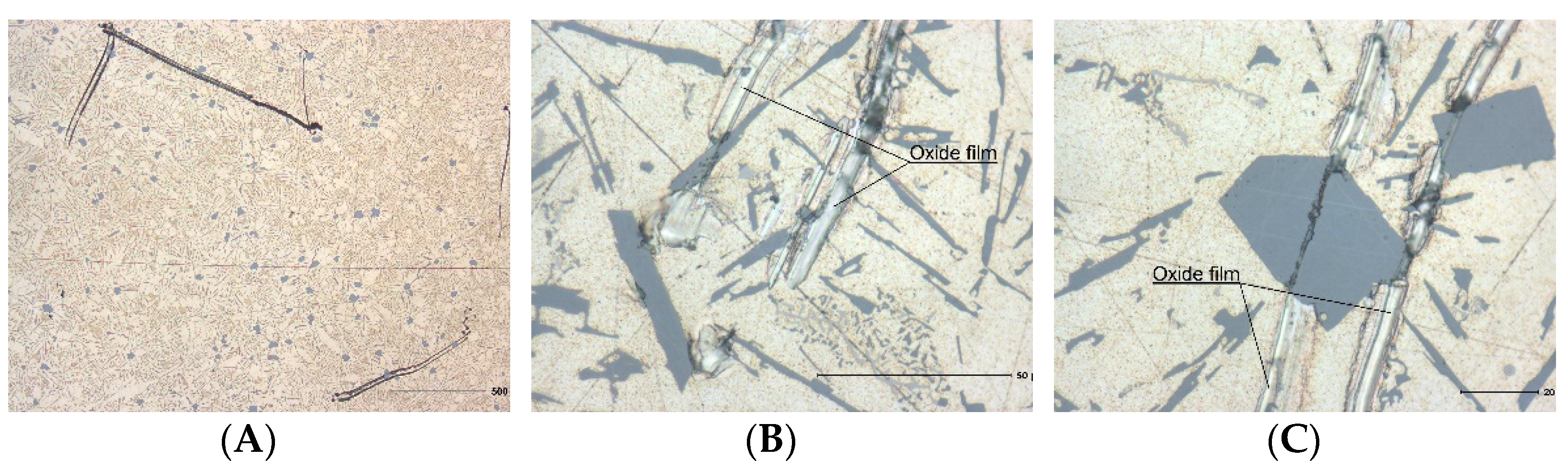
For the Al–Si system, the oxide film is still strong enough that the oxide film destruction does not occur, even on the melt surface at temperatures of 700–750 °C, which was implemented by the authors of [
14] to manufacture aluminum foam from oxide bubbles. To ensure film destruction as a result of gaseous suboxide formation, a temperature of over 1000 °C [
14] is required and is achieved as a result of hydrogen burning on the metal mirror. Micrographs prove these data; the ingot structure is dense though it contains large films (
Figure 4) that are partially destroyed during grinding (
Figure 4C).
Mechanical properties of the alloy (
Table 5) are slightly improved, which is indicative of oxide-reinforcing particles. The alloy’s relative elongation remains almost unchanged despite the embrittling oxide films. This indicates the presence of an insignificant number of disperse oxide particles. These oxide particles, as we can see from the results of SEM using EDS (
Figure 6 and
Table 6), possess the characteristic dimensions of 5 μm and a thickness of 0.1–0.5 μm, which are close to the alloy chemical composition using the relation of aluminum and silicon. Only oxide films located in the plane of study are acceptable to be subjected to electron microprobe analysis if the film is located perpendicularly; due to a small thickness, we may only note an insignificant increase in oxygen content with respect to the matrix (
Figure 7 and
Table 7). Yet, characteristic non-linear hollows, which can be identified as massive oxide spots, are present on one sample only—the composite based on AlSi12 alloy. Additionally, multiple linear scratches are present on all metallographic samples and the mentioned scratches occur from fine oxide particles during the process of grinding.
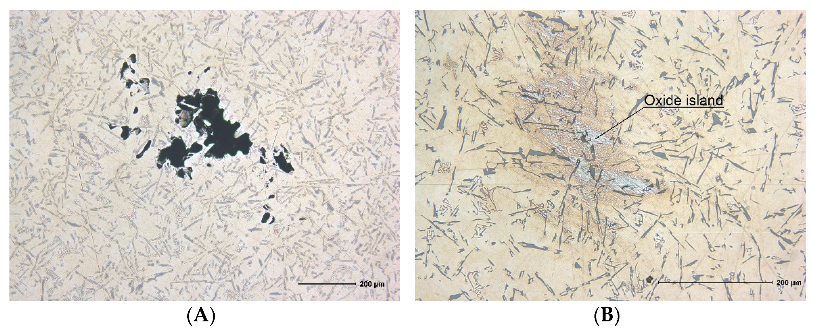
For the Al–Si–Zn system alloy, film destruction also occurs on the melt mirror, which is indicated by the insignificant oxide porosity (
Figure 5A). The ingot structure is mainly dense. Oxides in the structure are grouped into oxide islands (
Figure 5B), which occur as a result of oxide film division into minor fragments. These oxide islands are clusters of double films. The only detected pore is the result of the initial void destruction within the melt volume; however, the shape of the void indicates the presence of stress concentrators in the film, which are evidently zinc oxides.
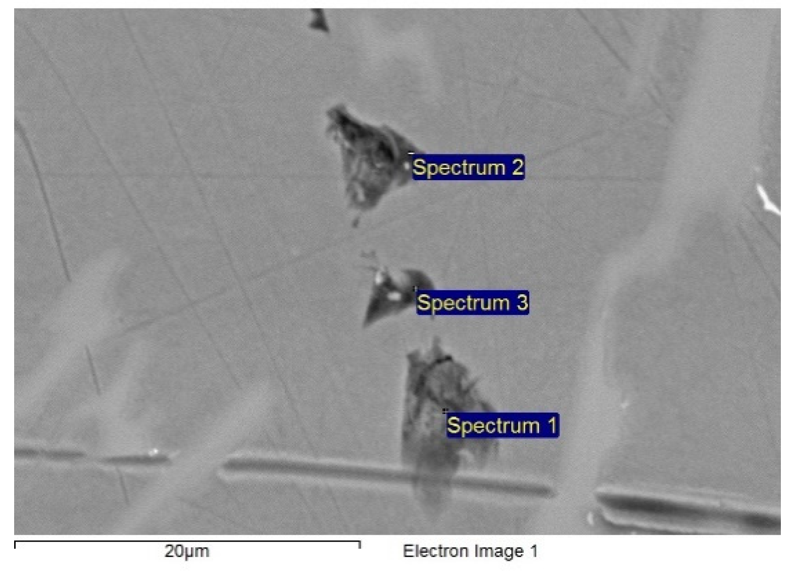
The mechanical properties of the alloy are also improved; however, this is not caused by oxide-dispersed particles, but rather by oxide islands with an average size of 200 µm, consisting of oxide films. The relative elongation remains almost unchanged. SEM and EDS studies of the metallographic sample micro-photo images (
Figure 8,
Table 8) demonstrated a wide range of oxide particle sizes in “islands”, with their thicknesses maintained, from isotropic (0.1–0.5 μm) to 5 μm. Oxide films cover silicon crystals similarly to the results obtained in [
5].
Based on test result analysis, it is possible to determine the critical value of the Pilling–Bedworth ratio for the basic alloying element, required to prevent destruction of oxide bubbles during floating. This value is within the range of 1.64–1.77; however, upon bubble floating, it is destroyed to make the finest possible fragments, otherwise, structures of double films and oxide islands can be produced. To do this, the oxide film needs to contain weakening components with a maximum Pilling–Bedworth ratio in a small amount. Iron-bearing alloys have such an effect on films. In Al–Fe systems, when the iron content is up to 0.25%, formation of magnetite (Fe
3O
4) or hematite (Fe
2O
3) in the film is insignificant and intermediate spinel–hercynite (FeAl
2O
4) is formed [
27] with a density close to that of γ–Al
2O
3 (3.8 g/cm
3), which is why it does not result in critical stresses in the film. In the case of a larger iron content, iron oxides are mainly found in the oxide film. Therefore, the Al–Si system is considered to be the best option for in situ composite production with an iron content above 0.25%. This is this composition that is deemed typical for aluminum secondary alloys as they tend to accumulate iron during re-melting. This, this very composition was used in [
2,
3,
4,
5].


