Article

Corner Strengthening by Local Thickening and Ausforming Using Planar Compression in Hot Stamping of Ultra-High Strength Steel Parts

1
Division of Systems Research, Faculty of Engineering, Yokohama National University, Yokohama 240-8501, Japan
2
Department of Mechanical Engineering, Toyohashi University of Technology, Toyohashi 441-8580, Japan
3
Department of Mechanical Engineering, Materials Science, and Ocean Engineering, Graduate School of Engineering Science, Yokohama National University, Yokohama 240-8501, Japan
*
Author to whom correspondence should be addressed.
Metals 2021, 11(12), 1977; https://doi.org/10.3390/met11121977
Submission received: 5 November 2021 / Revised: 26 November 2021 / Accepted: 7 December 2021 / Published: 8 December 2021
(This article belongs to the Special Issue Forming and Heat Treatment of Steel)

Abstract

:
Hot-stamped products are widely used for the body-in-white of an automobile as they are lightweight and improve crashworthiness. A hot-stamping process using planar compression was developed to strengthen corners of ultra-high strength parts by local thickening and hardening. In this process, the corners are thickened by compressing the blank in the planar direction with the upper and lower dies while blocking the movement of both edges with stoppers in the latter stage of forming. Thickening of the corners largely heightens the strength of the formed parts. Not only the thickness but also the hardness of the corner was increased by large plastic deformation and die quenching. For a hot hat-shaped part, a 30% increase in thickness and a 530 HV20 hardness around the corners were attained. The bending rigidity and strength of the formed parts thickened by 30% in the corners increased by 25% and 20%, respectively. In addition, the improvements of the part shape accuracy and the sidewall quenchability were obtained.

1. Introduction

The crashworthiness of automobiles is heightened by increasing the strength of body-in-white. Although the use of high strength steel sheets is generally employed to balance the high strength and weight reduction of the body-in-white, the application of hot stamping increases [1]. In hot stamping, quenchable steel sheets or tubes are transformed into austenite by heating to about 900 °C and then into martensite by die quenching [2,3]. The high strength of the hot-stamped parts is attained by the heat treatment. Hot-stamped components have a tensile strength of 1.5 GPa, much higher than cold-stamped ones from high strength steel sheets and are mainly employed as reinforcements in the body-in-white [4]. Although the risk level of hydrogen-induced delayed fracture is high for such high strength components [5], the risk for hot stamping is decreased by heating. Although the strength of hot-stamped components from conventional 22MnB5 steel sheets is about 1.5 GPa, steel sheets for producing 1.8 and 2.0 GPa components have been developed [6,7]. The increase in strength brings about the decreases in fracture toughness and the risk of hydrogen-induced delayed fracture. Castro et al. [8] increased the yield stress of the 22MnB5 steel sheets by bake hardening, whereas the tensile strength hardly increased. Chang et al. [9] increased the ductility and toughness of 2.0 GPa steel sheets by auto-tempering. Zhang et al. [10] illustrated that the hydrogen-induced delayed fracture property was improved by adding Nb in 22MnB5 steel. Jo et al. [11] examined the effect of Nb and Mo alloying on the resistance to the hydrogen embrittlement of 1.9 GPa steel sheets. However, it is desirable in industry to develop a hot-stamping process for enhancing the strength of components made of the 22MnB5 steel sheets, so that they have reliable weldability, toughness, and hydrogen embrittlement resistance, etc.
Since the strength and stiffness of components are influenced by a thickness distribution, the crashworthiness can be improved by optimising the thickness distribution without an increase in weight [12]. Tailored components having an appropriate strength distribution are produced by hot-stamping processes. Merklein et al. [13] comprehensively reviewed tailoring approaches of hot-stamping processes of quenchable steel sheets. The tailoring approaches of hot stamping are classified into heat treatment and tailored blanks [14]. To harden hot-stamped components, both austenite transformation by heating and martensite transformation by rapid cooling are required, and one of the two transformations is prevented in the approaches using heat treatment. For the prevention of the austenite transformation, Wilsius et al. [15] kept the temperature in a blank partially below the austenite transformation temperature by partition heating with heat shields, and Mu et al. [16] established a viscoplastic constitutive model of hot stamping using partition heating. Erturk et al. [17] have predicted the hardness distribution of tailored tempered blanks by finite element simulation using a thermomechanical metallurgical model. Wang et al. [18] utilised partial annealing to produce parts with tailored properties. Tang et al. [19] investigated the influence of temperature and deformation on phase transformation and hardening of hot-stamped components produced by tailored processes. Yun et al. [20] improved the tailored die quenching using material combination by adding lithium nitrate to transfer the phase of the material. Kong et al. [21] investigated the re-deformation characteristics of hot-stamped boron steel parts with tailored properties obtained by local induction heating and press hardening. Mori et al. [22] proposed partial resistance heating using copper bypasses for tailoring. On the other hand, tailored tempering in hot stamping is to prevent the martensite transformation by partial slow cooling, and partially heated dies are generally employed to decrease the cooling rate [23]. Nakagawa et al. [24] developed tailored tempering processes without die heating to avoid the complex structure of dies for heating.
Although the thickness of blanks is uniform for the tailoring approaches using heat treatment, the thickness is also changed for the tailored blanks. Tailor-welded blanks are made of sheets having different thicknesses and material compositions. From the tailor-welded blanks composed of quenchable and non-quenchable steel sheets, similar products to the approaches using heat treatment are hot stamped without control of heating and cooling [25]. Kang et al. [26] investigated the effects of laser welding and heating conditions on the microstructure in hot stamping of a tailor-welded Al-Si-coated blank. Mori et al. [27] exhibited that a low-cost mild steel sheet is available as a partner sheet for a quenchable steel sheet. On the other hand, patchwork blanks are employed for hot stamping as partial reinforcement, and resistance spot welding is used to join a main blank and patch unlike laser welding of tailor-welded blanks. Ouyang et al. [28] investigated the effect of heat treatment on microstructures and mechanical properties of welding spots of hot-stamped ultra-high strength steel patchwork blanks. Yogo et al. [29] examined the mechanical property and microstructure around the welds of hot-stamped components from both a finite element simulation and experiment. Yun et al. [30] rapidly cooled a thick patched portion of the formed component by dies with straight and conformal channels. Mori et al. [31] developed a combined process of hot stamping and mechanical joining for producing patchwork components to prevent non-uniform heating and forming defects. The thickness distributions of blanks used for hot stamping are also controlled by flexible rolling [32], successive forging [33], and orbital forming [34].
In conventional hot-stamping processes, the thickness distribution of formed components is not controlled and is strongly dependent on that of the blank. Although the thickness around the corners of formed components tends to decrease, the strength of the parts can be increased by locally thickening the corners, as shown in Figure 1. The tailor-welded blanks having different thicknesses are not applicable for such local thickening of the component. Han et al. [35] produced tailor-rolled blanks with thickness variations in both longitudinal and latitudinal directions. On the other hand, the thickness distribution of sheet metal parts is controlled by plate forging [36]. In plate forging processes, the thickness distribution is controlled by introducing compressive deformation to sheet metal forming, and this introduction is also attractive for hot stamping. Mori et al. [37] developed a 1-shot hot-stamping process consisting of resistance heating, forming, shearing, and die quenching, and locally increased the thickness of tooth tips of an ultra-high strength steel gear by partial compression. Although local thickening is more difficult than local thinning, the low flow stress at high temperatures in hot stamping makes local thickening comparatively easy.
In the present study, a hot-stamping process using planar compression was developed to produce ultra-high strength steel parts with thickened corners. The strength of the formed part is heightened by local thickening of the corners. Not only thickening but also hardening around the corners was attained by large plastic deformation at high temperatures and die quenching in the hot-stamping operation.

2. Corner Strengthening by Local Thickening and Ausforming Using Planar Compression in Hot Stamping

2.1. Approach of Local Thickening

The change in thickness around corners in hot-stamping processes is illustrated in Figure 2. In conventional draw bending and crash forming shown in Figure 2a,b, respectively, the stress around the corner is tensile, and thus the corner of the formed part becomes thin. To turn the tensile stress around the corner to the compressive stress, both edges of the blank are fixed with the stoppers in the latter stage of forming, and the sheet is compressed in the planar direction with the upper and lower dies, as shown in Figure 2c. The compressive stress is concentrated around the corners, and thus the corners are locally thickened.
The sequence of hot hat-shaped bending using planar compression is illustrated in Figure 3. The tools are composed of the upper and lower dies, and punch. The punch inserted into the lower die has a cushion and moves down after contact with the upper die. The lower die has stoppers for blocking the movement of both edges of the blank after the contact. The blank longer than the product shape is set and bent, as shown in Figure 3a,b. The sheet is planarly compressed after the contact of both edges with the stoppers, as shown in Figure 3d, and is die quenched by holding at the bottom dead centre, as shown in Figure 3e.
To accelerate local thickening of the four corners, the sidewalls and top are partially cooled by stopping the upper die for 1.5 s at a position of 9 mm above the bottom dead centre, as shown in Figure 3c. These zones are hardened by partial cooling, and thus the deformation around the corners increases in the subsequent forming.

2.2. Conditions of Hot Stamping

The designed setup for hot hat-shaped bending using the planar compression was installed in an 800 kN CNC servo press (SDE-8018, Amada Co., Ltd, Isehara, Japan). The dimensions of the forming tools and the hot-stamped part are given in Figure 4. The forming dies were made of carbon steel of S50C in JIS. An Al-Si-coated quenchable steel sheet 22MnB5 with 1.68 mm in thickness was employed. Length of the blank directly affects the degree of the planar compression, i.e., the thickening ratio of the corner. The length along with the cross-section of the hat shape is 100 mm, and additional length dL was changed between 0 and 16 mm to control the thickening of the four corners. The width of the blank was fixed at 90 mm. The perimeter of the hat-shaped bent part was about 100 mm, and the blank was not planarly compressed. The clearances between the upper and lower dies around the corner were increased for thickening. The blank was heated to T = 950 °C for 240 s in an electrical furnace (KBF894N1, Koyo Thermo systems Co., Ltd., Tenri, Japan). The molybdenum disulphide was applied to the tools to prevent galling. The average speed of the press slide during stamping was 300 mm/s.

3. Deformation Behaviour of Hot Stamping Using Planar Compression

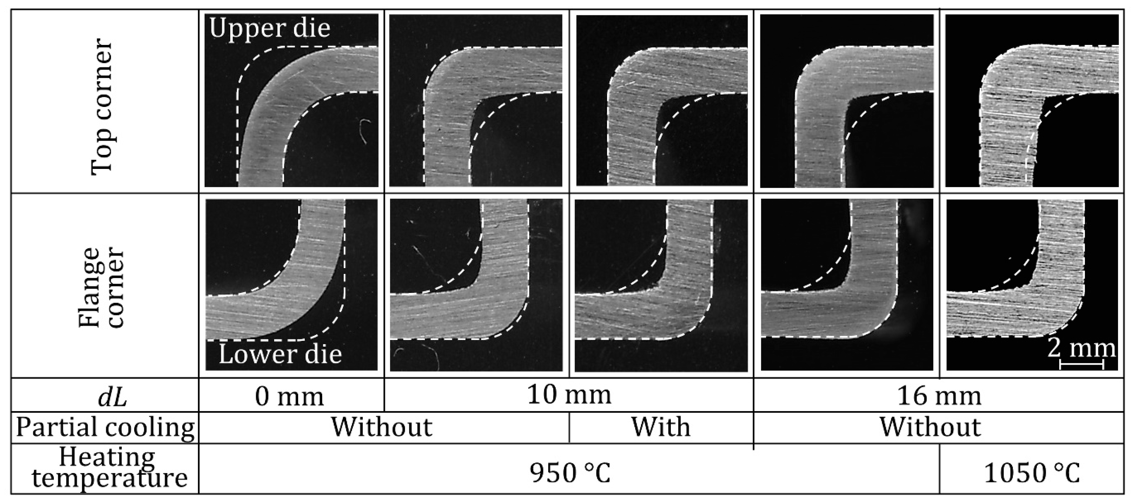
3.1. Local Thickening

The cross-sections of the hot hat-shaped bent parts without partial cooling for dL = 0 and 10 mm are shown in Figure 5. Although the sheet was hardly compressed for dL = 0 mm, the sheet for dL = 10 mm was planarly compressed by the contact with the stoppers. The cross-section for dL = 10 mm is sharper than that for dL = 0 mm, particularly around the corners. The planar compression is also useful for improving the shape accuracy of formed parts.
The cross-sections around the top and flange corners of the hot hat-shaped bent parts are shown in Figure 6, where the cross-sections for a heating temperature of 1050 °C are shown as a comparison. Although the sheets for dL = 0 mm are bent along the inner surfaces of the dies, the cross-sections for dL = 10 and 16 mm are in contact with the outer corners by the planar compression. Parts having sharp corners can be formed by decreasing the radius of the outer corners of the dies without cracking due to compressive stress.
The distributions of change in thickness in the hot hat-shaped bent parts are measured by a micrometre calliper (Mitutoyo, Kawasaki, Japan) and given in Figure 7. The thicknesses around the corners increase with increasing blank length. For L = 110 mm, the thickness of the corners increases by about 30%. Although the rise in heating temperature is effective in the increase in thickening, the heating temperature of 1050 °C is too high for the Al-Si-coated sheet due to the formation of an insufficient oxidation resistance layer. For the planar compression, not only the corners but also the sidewalls are thickened except for partial cooling shown in Figure 3c, while the effect of partial cooling on thickening around the corners is not much.
The forming force in hot hat-shaped bending using compression in-plane direction is shown in Figure 8. Although the forming force for dL = 0 mm without thickening is small due to bending, it increases remarkably above dL = 10 mm due to the plate forging deformation.
The variations in temperature at the top and flange corners and the middle of the sidewall without and with partial cooling are illustrated in Figure 9. The temperature was measured by k-type thermocouples with a diameter of 0.32 mm, which were welded to the specimen using spot welding. Although the decrease in temperature of the sidewall without partial cooling is slow, the temperature of the sidewall is rapidly dropped by partial cooling, and thus thickening of the sidewall is prevented by hardening as shown in Figure 7.

3.2. Increase in Hardness around Corners

The distributions of Vickers hardness in the hot hat-shaped bent parts were measured by a Vickers hardness tester (Mitutoyo, HV-112) and are shown in Figure 10, where the hardness of the die-quenched blank without deformation under sufficiently high pressure by means of sandwiching with flat platens is shown as a comparison. The hardness was measured at the centre of thickness. The hardness is increased by the planar compression, and the hardness around the corners is considerably high. For dL = 10 mm, the hardness attains to 530 HV20. The hardness around the corners increases with increasing blank length. Although the hardness in sidewalls of hot-stamped parts is generally low due to insufficient contact with dies, the quenchability of the sidewall is improved by sufficient contact for the planar compression.
As shown in Figure 10, the hardness around the corners is considerably higher than the hardness of the die-quenched sheet without forming under sufficiently high pressure. This mechanism was evaluated from the observation of microstructure.
The microstructures of the hot hat-shaped bent parts for dL = 0 and 16 mm are given in Figure 11. At first, the samples were polished with emery paper to obtain a smooth mirror-like surface, and then the polished specimens were lapped with alumina powder, having a 1 µm and 0.3 µm diameter. The polished surfaces were etched with Nital solution. An optical microscope was utilised for observation. Although all the microstructures are fully martensitic, the martensite for dL = 16 mm is finer than that for dL = 0 mm. The thickened corners undergo comparatively large plastic deformation and die quenching, and the hardness is increased by the deformation and quenching. This increase in hardness is similar to ausforming composed of rapid cooling, plastic deformation, and quenching [38]. Vaughan et al. [39] increased the strength and toughness of martensitic high strength steel components by ausforming with equal channel angular pressing.
To examine the increase in hardness by large deformation, a 22MnB5 rectangle plate with 3.2 mm in thickness heated to 950 °C was compressed, and the Vickers hardness at the centre of the thickness of the block was measured. Since the plate undergoes non-uniform deformation due to the friction at the interfaces, the equivalent strain at the centre was calculated from the commercial FEM code ABAQUS.
The 3D finite element model of compression of the rectangle specimen is shown in Figure 12. The specimen is simplified into a 1/4 symmetrical model. The upper and lower flat platens are considered as rigid surfaces. The temperature of the specimen during the compression test was reduced from 800 to 700 °C. Hence, to ignore the temperature change during compression, the flow stress of the specimen was adjusted to change from 800 to 700 °C gradually by using the results of Naderi et al. [40]. By adjusting a friction coefficient in simulations, a reasonable agreement was obtained between the numerical and experimental results of compression loads. The utilised friction coefficient of with and without lubrication were 0.04 and 0.24, respectively. The distribution of the equivalent strain after compression is shown in Figure 13.
The relationship between the Vickers hardness and the equivalent strain at the centre of the cross-section is shown in Figure 14. The equivalent strain of the centre of the specimen was extracted from Figure 13. The hardness increases linearly below ε ¯ = 0.8. The hardness for ε ¯ = 0.8 reaches 600 HV10, and it becomes constant above that. The obtained graph is almost similar to the results of modified ausforming by Sugimoto et al. [41] and so the proposed local thickening technique is a similar process to modified ausforming. In modified ausforming, increasing dislocation density by plastic deformation refines the martensite block size. Therefore, an increase in hardness increases with attained equivalent stress.
The increase in hardness around the corners shown in Figure 10 is induced by plastic deformation of thickening. It was found that the large plastic deformation in hot stamping is effective in increasing the product strength by ausforming.

3.3. Strength of Hot-Stamped Part Using Planar Compression

The distributions of strength estimated as a product of the hardness and thickness are shown in Figure 15. The strength becomes large around the top and flange corners, and the corner strength increases with increasing blank length. By using partial cooling, the difference of strength between the corner and sidewall becomes large. The corner strength is enhanced by the increase in not only thickness but also hardness.
A three-point bending test was performed to examine the effect of corner thickening on the strength of the hot-stamped part. The bending test was carried out by means of a Yuken servo-hydraulic press, with a maximum capacity of 300 kN under displacement control. In this test, the blank length was increased from 90 to 270 mm. The bending setup and bent parts for dL = 10 mm welded with high strength steel sheets are shown in Figure 16. Both sidewalls and flanges opened by loading in the three-point bending test. Small strips of high strength steel sheets with 1.4 mm in thickness were spot welded on both flanges in a ladder shape to prevent the opening of the sidewall.
The bending load–punch stroke curves in three-point bending of the hot-hat bent parts using the planar compression for dL = 0 and 10 mm are shown in Figure 17. The bending load is divided by the weight of the part to eliminate the effect of weight. The maximum bending load and rigidity per unit weight with local thickening of dL = 10 mm is about 20% and 25% higher than without local thickening, respectively. The hot-hat bent parts for the dL = 0 and 10 mm after the bending test are shown in Figure 18. The top corners at the centre are fractured. Hence, the strengthening of the corner is effective to improve the bending strength of the beam members. However, as the fracture behaviours of the bent parts are similar, conventional design methods of products can be utilised, especially in automobile industries, due to the importance of fracture mechanisms.

3.4. Surface Quality after Local Thickening

An Al-Si coated sheet is commonly used for hot stamping to prevent the occurrence of oxide scale by heating and to guarantee successful adhesion of the painted parts. A formed intermetallic coating layer by heating tends to crack owing to its brittleness [42]. Since severe plastic deformation is attained in local thickening, the surface condition after hot stamping was examined. The surface appearances of the hot-hat bent parts for dL = 0 mm and 10 mm are shown in Figure 19. Small cracks are observed at the top corner for both conditions. Plastic tensile deformation is generated on the outer of the corner by bending and a crack tends to occur even for dL = 0 mm. For dL =16 mm, not only the crack but also the peeling of the coating at the sidewall is observed. The brittle intermetallic layer was cracked and detached from a substratum by planar compression, and the sliding of the upper die peeled the coating.
The relationship between the surface roughness at the sidewall and the additional length of the blank is shown in Figure 20. Surface roughness was measured with the Mitutoyo SURFTEST SJ-210 series. The measuring direction was the height of the sidewall, and the path length of the stylus was 2 mm. Surface roughness increases with increasing in additional length, i.e., increasing in thickening above dL = 6 mm. However, it is necessary to investigate whether these cracks and peeling are acceptable in terms of paintability and corrosion resistance.

4. Conclusions

Hot stamping can produce ultra-high strength steel components for improving the crashworthiness of automobiles, and a further increase in strength of the components is desired in industry. In the present study, a hot-stamping process using the planar compression was developed to enhance the strength of formed components, and the following results were obtained:
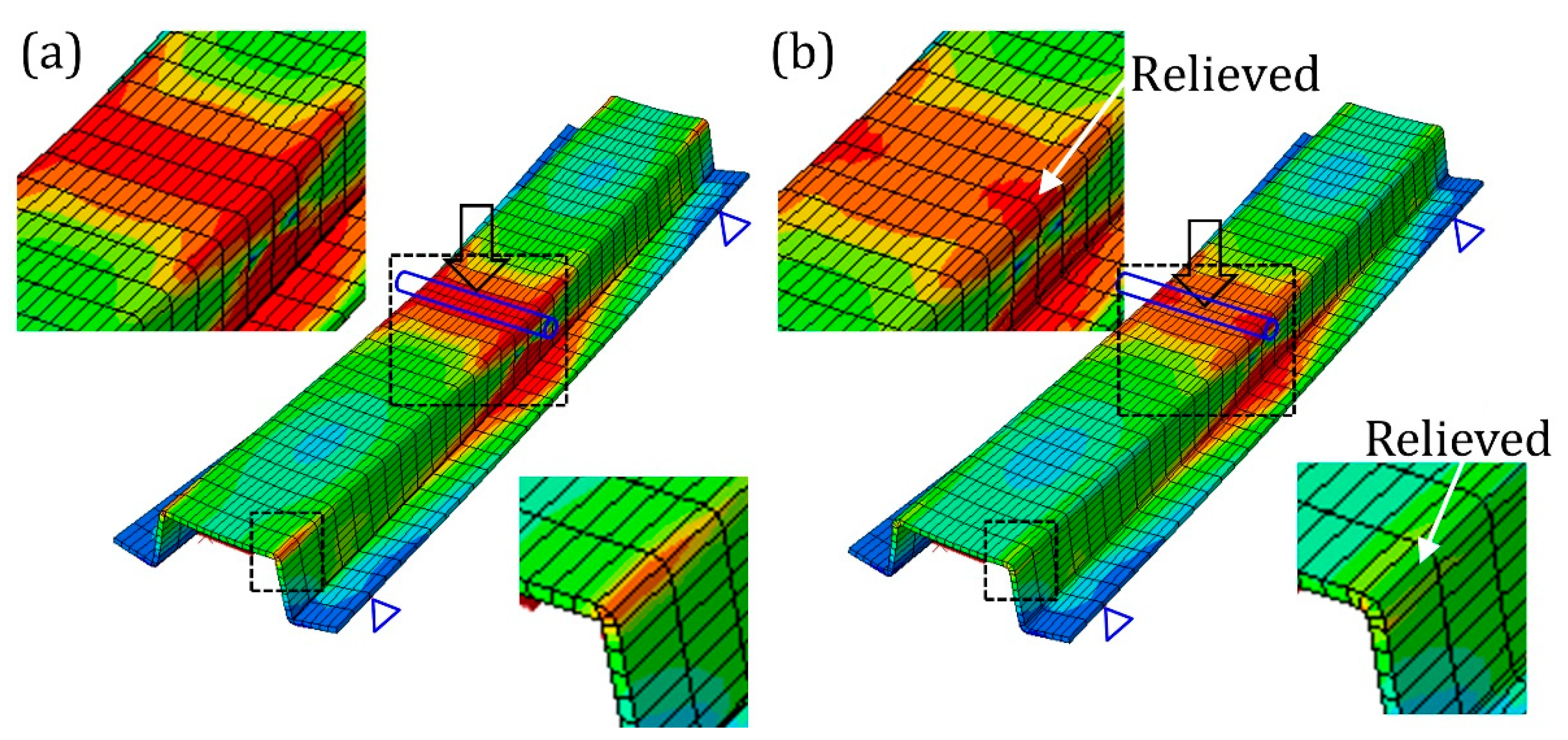
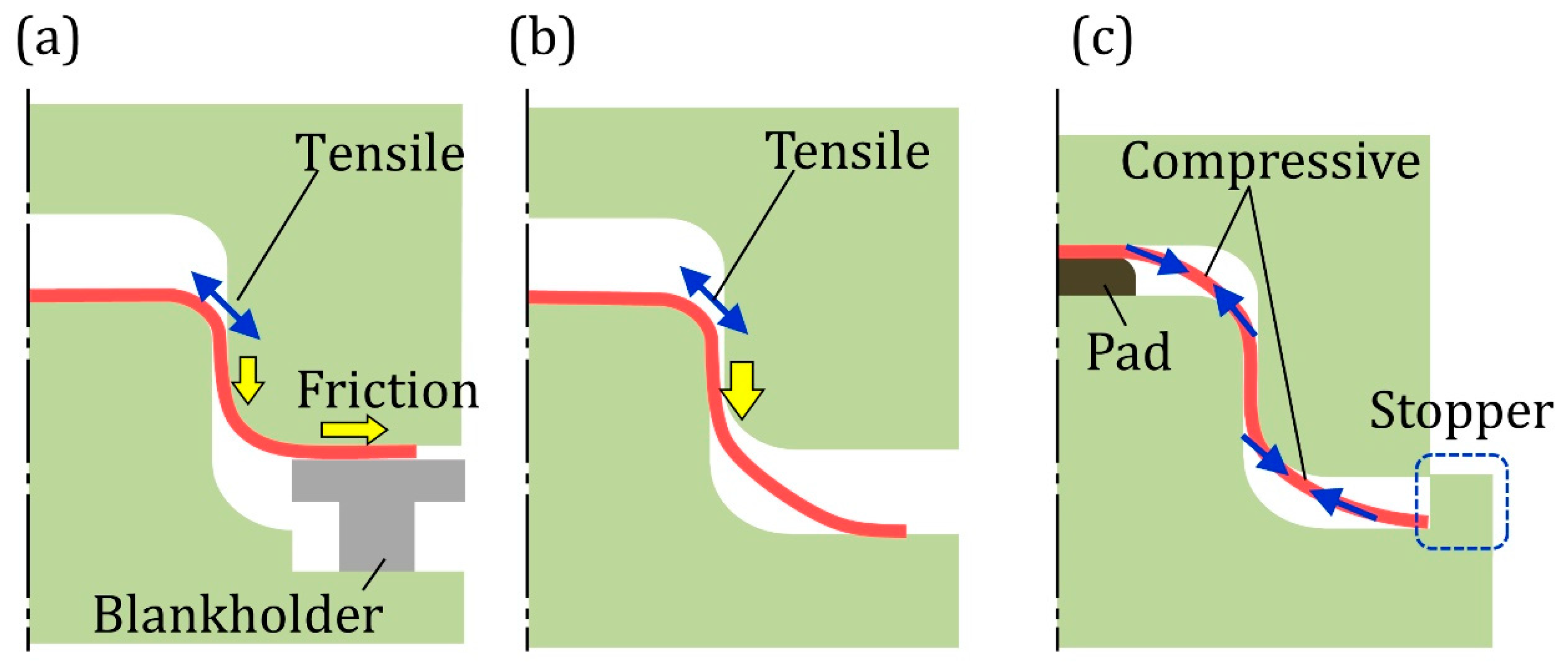
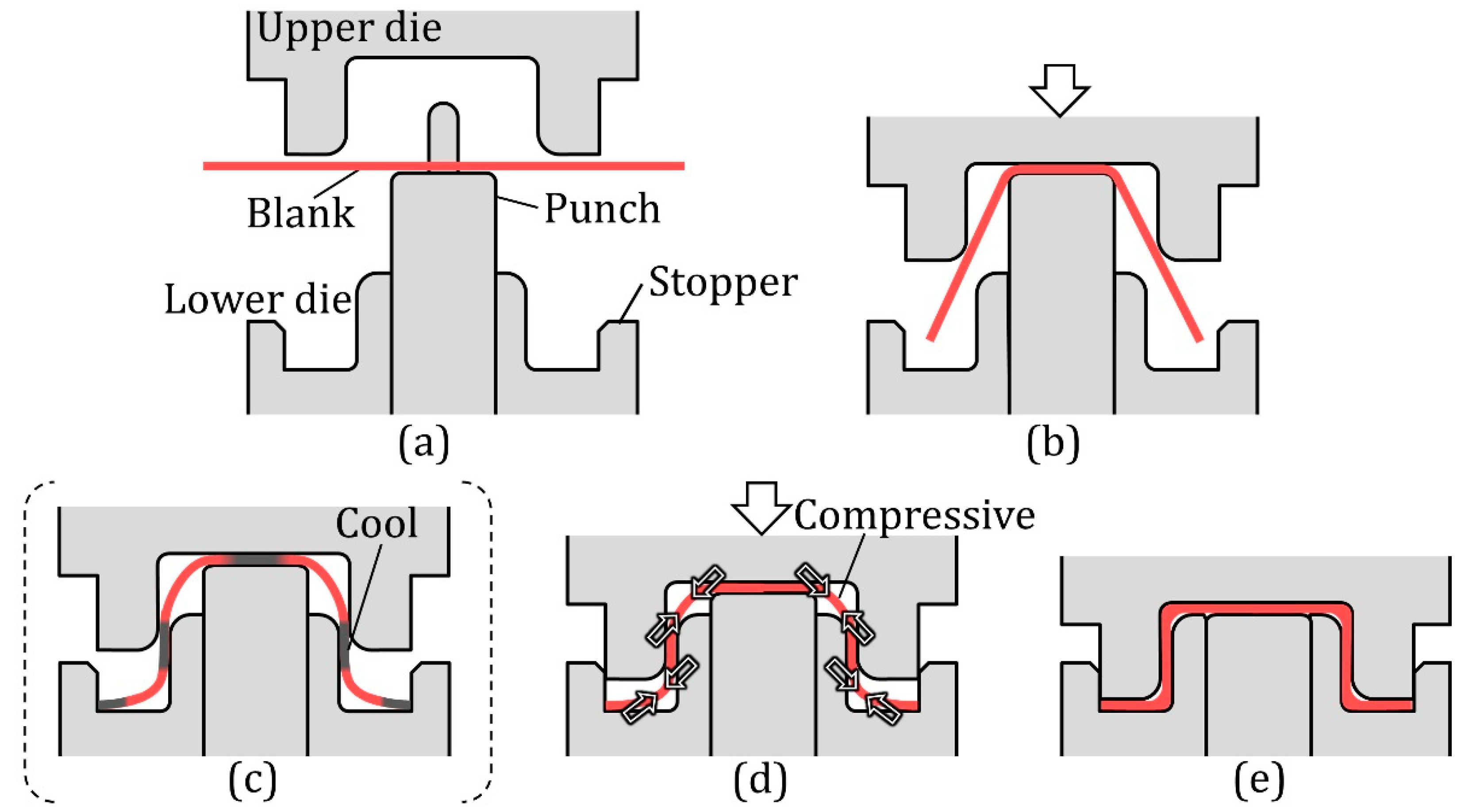
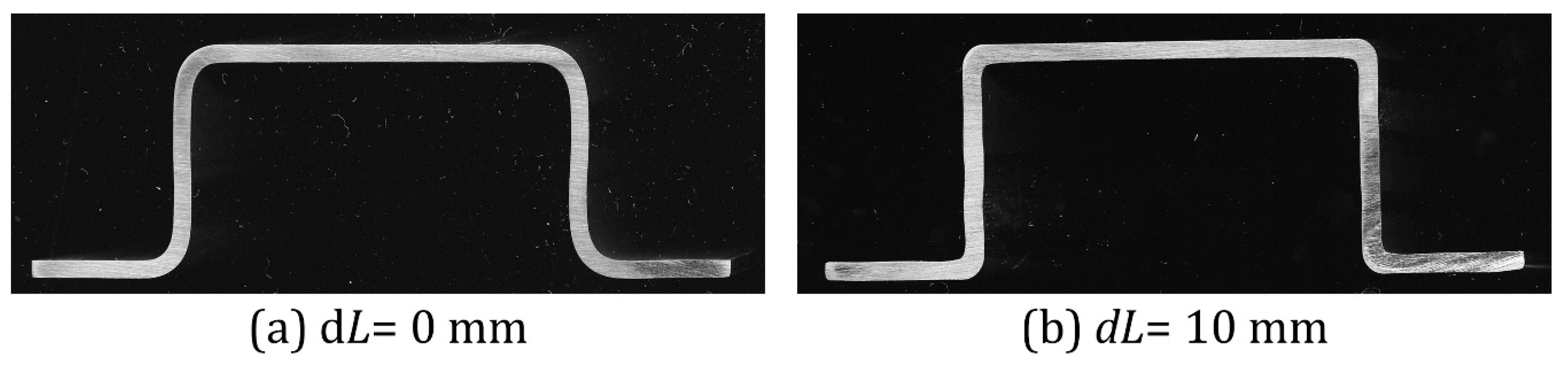
  • The top and flange corners of a hat-shaped part were thickened by blocking the movement of both edges of the blank with stoppers of the lower dies during the latter stage of hot stamping.
  • The strength of the formed components was heightened by the increase in not only thickness but also hardness.
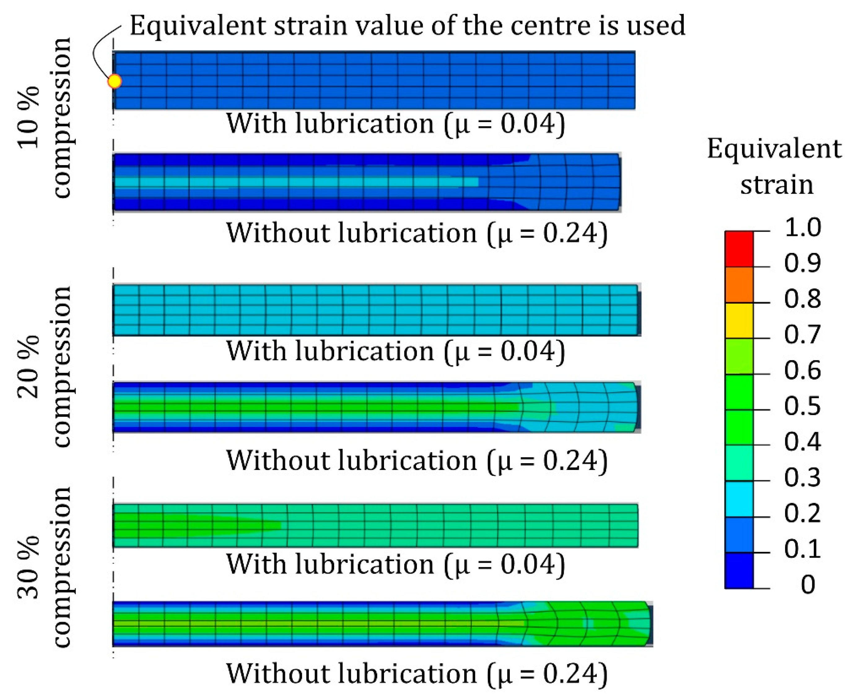
  • The increase in hardness was induced by the large plastic deformation of thickening, i.e., the ausforming was utilised for hot stamping.
  • The hardness increased linearly below ε ¯ = 0.8, and it reached 600 HV10 by ausforming under die quenching, which is equivalent to 1.8 GPa parts in tensile strength.
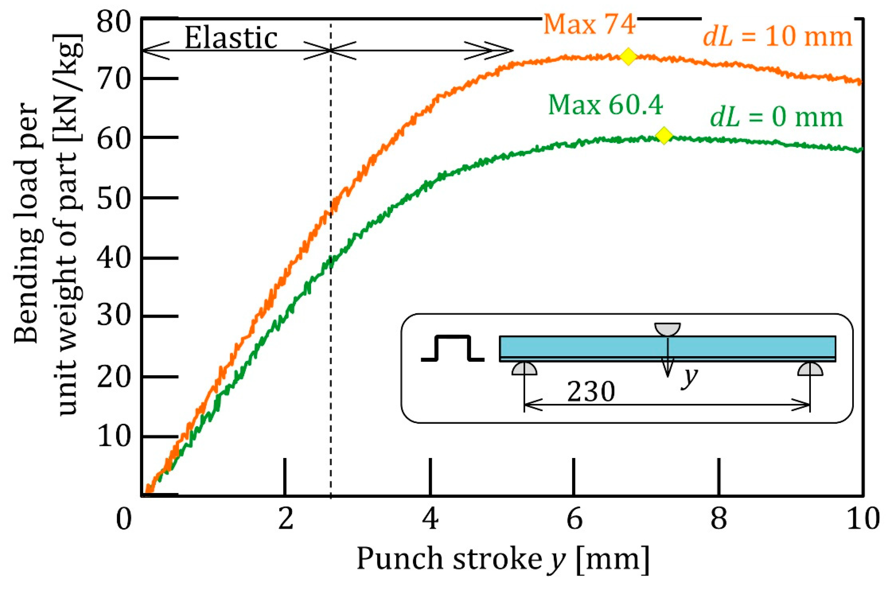
  • A 20% increase in bending load and high shape accuracy were obtained by the planar compression.
The advantageousness of conventional hot-stamping processes of 1.5 GPa ultra-high strength steel parts lowers due to the advent of 1.5 GPa ultra-high strength steel sheets used for cold stamping. It is desirable to increase the strength of hot-stamped components. Not only an increase in material strength but also optimisation of component shapes is a solution. In conventional hot-stamping processes, the distribution in the thickness of components is hardly controlled, except in the utilisation of tailored blanks. Because the flow stress of heated blanks is low, it is comparatively easy to control the thickness distribution in hot stamping. Although plate forging processes for controlling the thickness distribution are mainly cold processes, the application of plate forging to hot stamping increases.
In the present process, the strength of hot-stamped parts was increased by local thickening using planar compression. The increase in not only thickness but also hardness was attained by local thickening. This is a kind of thermomechanical processing. The shape accuracy of the formed parts and the quenchability of the sidewall were also improved.
The proposed method is attractive for improvement in parts strength and lightening of the structure parts. However, the remaining challenges should still be studied. Ausforming characteristics in die quenching of 22MnB5 and the thickening behaviour of curved and complex parts should be discussed. Furthermore, prevention methods for the peeling of coating should be developed.

Author Contributions

Investigation, T.M., K.-i.M., H.H., A.T.-A. and R.I.; writing—original draft preparation, T.M.; writing—review and editing, T.M., K.-i.M. and A.T.-A.; visualisation, T.M., A.T.-A., H.H. and R.I.; supervision, T.M.; project administration, T.M.; funding acquisition, T.M. and K.-i.M. All authors have read and agreed to the published version of the manuscript.

Funding

This work was supported by grant-supported research in the Suzuki Foundation and JSPS KAKENHI Grant-in-Aid for Scientific Research (B) of Number JP18H01749.

Institutional Review Board Statement

Not applicable.

Informed Consent Statement

Not applicable.

Data Availability Statement

The data that support the findings of this study are available from the corresponding author on reasonable request.

Conflicts of Interest

The authors declare no conflict of interest.

References

  1. Tisza, M.; Czinege, I. Comparative study of the application of steels and aluminium in lightweight production of automotive parts. Int. J. Lightweight Mater. Manuf. 2018, 1, 229–238. [Google Scholar] [CrossRef]
  2. Maeno, T.; Mori, K.; Sakagami, M.; Nakao, Y.; Talebi-Anaraki, A. Minimisation of heating time for full hardening in hot stamping using direct resistance heating. J. Manuf. Mater. Process. 2020, 4, 80. [Google Scholar] [CrossRef]
  3. Talebi-Anaraki, A.; Maeno, T.; Ikeda, R.; Morishita, K.; Mori, K. Quenchability improvement and control simplification by ice mandrel in hot stamping of ultra-high strength steel hollow parts. J. Manuf. Process. 2021, 64, 916–926. [Google Scholar] [CrossRef]
  4. Billur, E. (Ed.) Chapter 1 Introduction. In Hot stamping of Ultra High-Strength Steels: From a Technological and Business Perspective; Springer Nature: Cham, Switzerland, 2018; pp. 1–18. [Google Scholar]
  5. Mori, K.-I.; Abe, Y.; Sedoguchi, K. Delayed fracture in cold blanking of ultra-high strength steel sheets. CIRP Ann. Manuf. Technol. 2019, 68, 297–300. [Google Scholar] [CrossRef]
  6. Tokizawa, A.; Yamamoto, K.; Takemoto, Y.; Senuma, T. Development of 2000 MPa class hot stamped steel components with good toughness and high resistance against delayed fracture. In Proceedings of the 4th International Conference on Hot Sheet Metal Forming of High-Performance Steel–CHS2, Luleå, Sweden, 9–12 June 2013; pp. 473–479.6. [Google Scholar]
  7. Gerber, T.; Heckelmann, I.; Diaz, N.V.; Lenze, F.J. Efforts in expanding the portfolio of hot forming steel material concepts. In Proceedings of the 4th International Conference on Hot Sheet Metal Forming of High-Performance Steel—CHS2, Luleå, Sweden, 9–12 June 2013; pp. 145–152. [Google Scholar]
  8. De Castro, M.R.; Monteiro, W.A.; Politano, R. Enhancements on strength of body structure due to bake hardening effect on hot stamping steel. Int. J. Adv. Manuf. Technol. 2019, 100, 771–782. [Google Scholar] [CrossRef]
  9. Chang, Z.; Li, Y.; Wu, D. Enhanced ductility and toughness in 2000 MPa grade press hardening steels by auto-tempering. Mater. Sci. Eng. A 2020, 784, 139342. [Google Scholar] [CrossRef]
  10. Zhang, S.Q.; Huang, Y.H.; Sun, B.T.; Liao, Q.L.; Lu, H.Z.; Jian, B.; Mohrbacher, H.; Zhang, W.; Guo, A.M.; Zhang, Y. Effect of Nb on hydrogen-induced delayed fracture in high strength hot stamping steels. Mater. Sci. Eng. A 2015, 626, 136–143. [Google Scholar] [CrossRef]
  11. Jo, M.C.; Yoo, J.; Kim, S.; Kim, S.; Oh, J.; Bian, J.; Sohn, S.S.; Lee, S. Effects of Nb and Mo alloying on resistance to hydrogen embrittlement in 1.9 GPa-grade hot-stamping steels. Mater. Sci. Eng. A 2020, 789, 139656. [Google Scholar] [CrossRef]
  12. Mallick, P.K. (Ed.) Chapter 10—Designing lightweight vehicle body. In Materials, Design and Manufacturing for Lightweight Vehicles, 2nd ed.; Woodhead Publishing in Materials: Sawston, UK, 2021; pp. 405–432. [Google Scholar] [CrossRef]
  13. Merklein, M.; Wieland, M.; Lechner, M.; Bruschi, S.; Ghiotti, A. Hot stamping of boron steel sheets with tailored properties: A review. J. Mater. Process. Technol. 2016, 228, 11–24. [Google Scholar] [CrossRef]
  14. Mori, K.-I.; Bariani, P.; Behrens, B.-A.; Brosius, A.; Bruschi, S.; Maeno, T.; Merklein, M.; Yanagimoto, J. Hot stamping of ultra-high strength steel parts. CIRP Ann. Manuf. Technol. 2017, 66, 755–777. [Google Scholar] [CrossRef]
  15. Wilsius, J.; Tavernier, B.; Abou-Khalil, D. Experimental and numerical investigation of various hot stamped B-pillar concepts based on Usibor® 1500P. In Proceedings of the 3rd International Conference on Hot Sheet Metal Forming of High-Performance Steel—CHS2, Kassel, Germany, 13–17 June 2011; pp. 427–435. [Google Scholar]
  16. Mu, Y.; Zhou, J.; Wang, B.; Wang, Q.; Ghiotti, A.; Bruschi, S. Numerical simulation of hot stamping by partition heating based on advanced constitutive modelling of 22MnB5 behaviour. Finite Elem. Anal. Des. 2018, 147, 34–44. [Google Scholar] [CrossRef]
  17. Erturk, S. Simulation of Tailored Tempering with a thermo-mechanical metallurgical model in autoform plus. In AIP Conference Proceedings; American Institute of Physics: College Park, MD, USA, 2011; Volume 1383, p. 610. [Google Scholar] [CrossRef]
  18. Wang, Z.J.; Liu, P.X.; Xu, Y.; Wang, Y.L.; Zhang, Y.S. Hot stamping of high strength steel with tailored properties by two methods. In Proceedings of the Procedia Engineering, Nogaya, Japan, 19–24 October 2014; pp. 1725–1730. [Google Scholar]
  19. Tang, B.T.; Wang, Q.L.; Bruschi, S.; Ghiotti, A.; Bariani, P.F. Influence of temperature and deformation on phase transformation and Vickers hardness in tailored tempering process: Numerical and experimental verifications. ASME J. Manuf. Sci. Eng. 2014, 136, 051018. [Google Scholar] [CrossRef]
  20. Yun, S.; Lee, S.H.; Song, K.S.; Cho, W.; Kim, Y. Performance improvement of tailored die quenching using material combinations with phase change material in hot stamping. Int. J. Heat Mass Transf. 2020, 161, 120286. [Google Scholar] [CrossRef]
  21. Kong, L.; Peng, Y.; Liu, C. Research on the re-deformation characteristics of hot stamping of boron steel parts with tailored properties. Metals 2020, 10, 1136. [Google Scholar] [CrossRef]
  22. Mori, K.-I.; Maeno, T.; Mongkolkaji, K. Tailored die quenching of steel parts having strength distribution using bypass resistance heating in hot stamping. J. Mater. Process. Technol. 2013, 213, 508–514. [Google Scholar] [CrossRef]
  23. Fernandez, B.; Zarate, J.; Garcia, I.; Varela, S. Tailored strategies in press hardening. In Proceedings of the 3rd International Conference on Hot Sheet Metal Forming of High-Performance Steel—CHS2, Kassel, Germany, 13–17 June 2011; pp. 437–446. [Google Scholar]
  24. Nakagawa, Y.; Mori, K.-I.; Suzuki, Y.; Shimizu, Y. Tailored tempering without die heating in hot stamping of ultra-high strength steel parts. Mater. Des. 2020, 192, 108712. [Google Scholar] [CrossRef]
  25. Merklein, M.; Johannes, M.; Lechner, M.; Kuppert, A. A review on tailored blanks-production, applications and evaluation. J. Mater. Process. Technol. 2014, 214, 151–164. [Google Scholar] [CrossRef]
  26. Kang, M.; Kim, Y.-M.; Kim, C. Effect of heating parameters on laser welded tailored blanks of hot press forming steel. J. Mater. Process. Technol. 2016, 228, 137–144. [Google Scholar] [CrossRef]
  27. Mori, K.-I.; Suzuki, Y.; Yokoo, D.; Nishikata, M.; Abe, Y. Steel sheets partnered with quenchable sheet in hot stamping of tailor-welded blanks and its application to separation prevention of fractured components. Int. J. Adv. Manuf. Technol. 2020, 111, 725–734. [Google Scholar] [CrossRef]
  28. Ouyang, X.; Zhang, Z.; Jia, H.; Ren, M.; Sun, Y. Study on the Effect of Heat Treatment on Microstructures and High Temperature Mechanical Properties of Welding Spots of Hot Stamped Ultra-High Strength Steel Patchwork Blanks. Metals 2021, 11, 1033. [Google Scholar] [CrossRef]
  29. Yogo, Y.; Kurato, N.; Iwata, N. Investigation of hardness change for spot welded tailored blank in hot stamping using CCT and deformation-CCT diagrams. Met. Mater. Trans. A 2018, 49, 2293–2301. [Google Scholar] [CrossRef]
  30. Yun, S.; Kwon, J.; Cho, W.; Lee, D.; Kim, Y. Performance improvement of hot stamping die for patchwork blank using mixed cooling channel designs with straight and conformal channels. Appl. Them. Eng. 2020, 165, 114562. [Google Scholar] [CrossRef]
  31. Mori, K.-I.; Kaido, T.; Suzuki, Y.; Nakagawa, Y.; Abe, Y. Combined process of hot stamping and mechanical joining for producing ultra-high strength steel patchwork components. J. Manuf. Process. 2020, 59, 444–455. [Google Scholar] [CrossRef]
  32. Grüber, M.; Kopp, R.; Hirt, G. Flexible rolling. In 60 Excellent Inventions in Metal Forming; Tekkaya, A.E., Homberg, W., Brosius, A., Eds.; Springer: Berlin/Heidelberg, Germany, 2015; pp. 213–218. [Google Scholar]
  33. Tajul, L.; Maeno, T.; Kinoshita, T.; Mori, K.-I. Successive forging of tailored blank having thickness distribution for hot stamping. Int. J. Adv. Manuf. Technol. 2017, 89, 3731–3739. [Google Scholar] [CrossRef]
  34. Vogel, M.; Merklein, M. Manufacturing of tailored blanks by orbital forming with a two-sided material thickening. J. Mater. Process. Technol. 2019, 287, 116491. [Google Scholar] [CrossRef]
  35. Han, S.; Hwang, T.; Oh, I.; Choi, M.; Moon, Y.H. Manufacturing of tailor-rolled blanks with thickness variations in both the longitudinal and latitudinal directions. J. Mater. Process. Technol. 2018, 256, 172–182. [Google Scholar] [CrossRef]
  36. Mori, K.I.; Nakano, T. State-of-the-art of plate forging in Japan. Prod. Eng. 2016, 10, 81–91. [Google Scholar] [CrossRef]
  37. Mori, K.-I.; Maeno, T.; Yamada, H.; Matsumoto, H. 1-shot hot stamping of ultra-high strength steel parts consisting of resistance heating, forming, shearing and die quenching. Int. J. Mach. Tools Manufact. 2015, 89, 124–131. [Google Scholar] [CrossRef]
  38. Tekkaya, A.; Allwood, J.; Bariani, P.; Bruschi, S.; Cao, J.; Gramlich, S.; Groche, P.; Hirt, G.; Ishikawa, T.; Löbbe, C.; et al. Metal forming beyond shaping: Predicting and setting product properties. CIRP Ann. Manuf. Technol. 2015, 64, 629–653. [Google Scholar] [CrossRef]
  39. Vaughan, M.; Samimi, P.; Gibbons, S.; Abrahams, R.; Harris, R.; Barber, R.; Karaman, I. Exploring performance limits of a new martensitic high strength steel by ausforming via equal channel angular pressing. Scr. Mater. 2020, 184, 63–69. [Google Scholar] [CrossRef]
  40. Naderi, M.; Durrenberger, L.; Molinari, A.; Black, W. Constitutive relationships for 22MnB5 boron steel deformed isothermally at high temperatures. Mater. Sci. Eng. A-Struct. Mater. Prop. Microstruct. Process. 2008, 478, 130–139. [Google Scholar] [CrossRef]
  41. Sugimoto, A.; Tanaka, T.; Oki, T.; Wakimon, K. Impact of improved ausforming on the structure of spring steel. Trans. Jpn. Soc. Spring Eng. 1989, 34, 38–43. [Google Scholar] [CrossRef] [Green Version]
  42. Fan, D.W.; De Cooman, B.C. State-of-the-Knowledge on Coating Systems for Hot Stamped Parts. Steel Res. Int. 2012, 83, 412–433. [Google Scholar] [CrossRef]
Figure 1. Stress concentration around corners of components produced by sheet metal forming by action of external force and relief by local thickening of corners for (a) uniform thickness and (b) corner thickening of 30%.
Metals 11 01977 g001
Figure 2. Changes in thickness around corners in hot-stamping processes: (a) draw bending, (b) crash forming and (c) compression bending.
Metals 11 01977 g002
Figure 3. Sequence of hot hat-shaped bending using compression in-plane direction: (a) set of blank, (b) bending, (c) partial cooling for 1.5 s, (d) thickening of corner and (e) die quenching.
Metals 11 01977 g003
Figure 4. (a) Dimensions of dies for hot hat-shaped bending using planar compression and (b) hot-stamped part.
Metals 11 01977 g004
Figure 5. Cross-sections of hot hat-shaped bent parts without partial cooling for (a) dL = 0 mm and (b) dL = 10 mm.
Metals 11 01977 g005
Figure 6. Cross-sections around top and flange corners of hot hat-shaped bent parts.
Metals 11 01977 g006
Figure 7. Distributions of change in thickness in hot hat-shaped bent parts.
Metals 11 01977 g007
Figure 8. Forming force in hot hat-shaped bending using compression in-plane direction.
Metals 11 01977 g008
Figure 9. Variation in temperature at top and flange corners and middle of sidewall for (a) without and (b) with partial cooling.
Metals 11 01977 g009
Figure 10. Distributions of Vickers hardness in hot hat-shaped bent parts.
Metals 11 01977 g010
Figure 11. Microstructures of hot hat-shaped bent parts for dL = 0 and 16 mm.
Metals 11 01977 g011
Figure 12. Finite element simulation model of compression of rectangle specimen.
Metals 11 01977 g012
Figure 13. Calculated distribution of the equivalent strain after compression.
Metals 11 01977 g013
Figure 14. Relationship between Vickers hardness and equivalent strain at centre of cross-section.
Metals 11 01977 g014
Figure 15. Distribution of strength estimated as product of hardness and thickness.
Metals 11 01977 g015
Figure 16. (a) Bending setup for hot-hat bent parts and (b) bent parts for dL = 10 mm welded with high strength steel sheets.
Metals 11 01977 g016
Figure 17. Bending load–punch stroke curve in three-point bending of hot-hat bent parts using planar compression with and without partial cooling.
Metals 11 01977 g017
Figure 18. Hot-hat bent parts after bending test for (a) dL = 0 mm and (b) 10 mm.
Metals 11 01977 g018
Figure 19. Surface appearances of hot-hat bent parts for dL = 0 mm and 10 mm.
Metals 11 01977 g019
Figure 20. Relationship between surface roughness of sidewall and additional length of blank.
Metals 11 01977 g020
Publisher’s Note: MDPI stays neutral with regard to jurisdictional claims in published maps and institutional affiliations.

