
Effect of Cryogenic Treatment on Microstructure, Mechanical Properties and Distortion of Carburized Gear Steels


Abstract
:1. Introduction
2. Materials and Methods
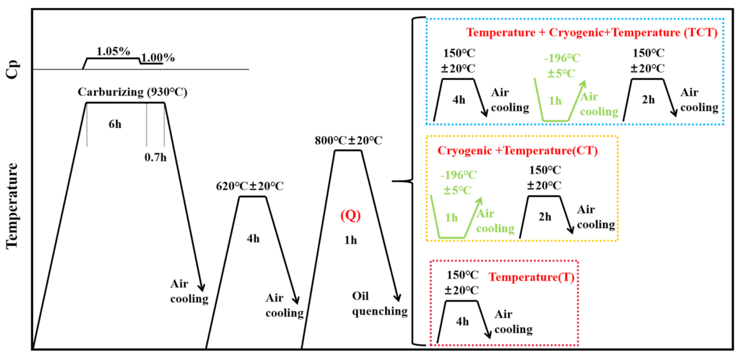
2.1. Materials and Heat Treatment
2.2. Microstructural Characterization
2.3. Tests for Hardness and Wear Resistance
3. Results
3.1. Effect of Cryogenic Treatment on Microstructure
3.2. Effect of Cryogenic Treatment and Tempering on Mechanical Properties
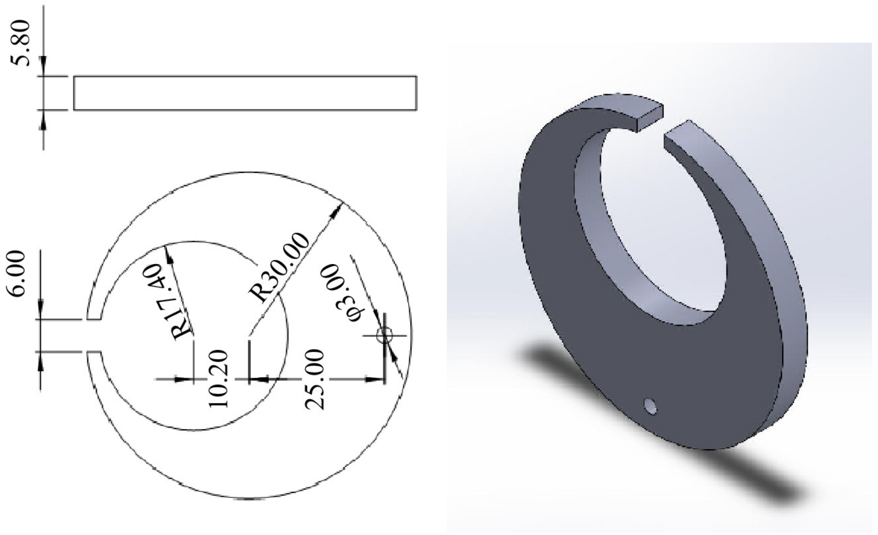
3.3. Effect of Cryogenic Treatment on Distortion of Navy C-Ring Samples
4. Conclusions
- (1)
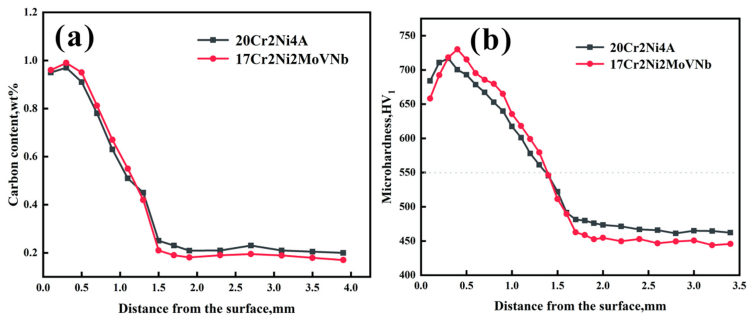
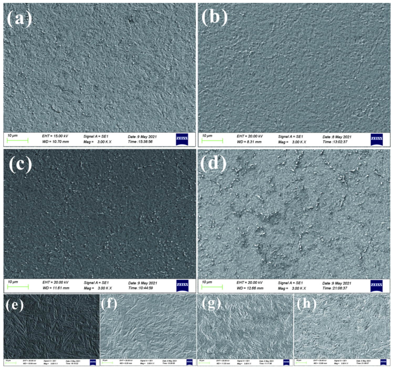
- The 17Cr2Ni2MoVNb and 20Cr2Ni4A steels had similar microstructures after carburizing, which are composed of high-carbon needle-like martensite, carbides and retained austenite in the case and low-carbon lathe martensite in the core matrix. The depth of the carburized layer was about 1.4 (±0.05) mm.
- (2)
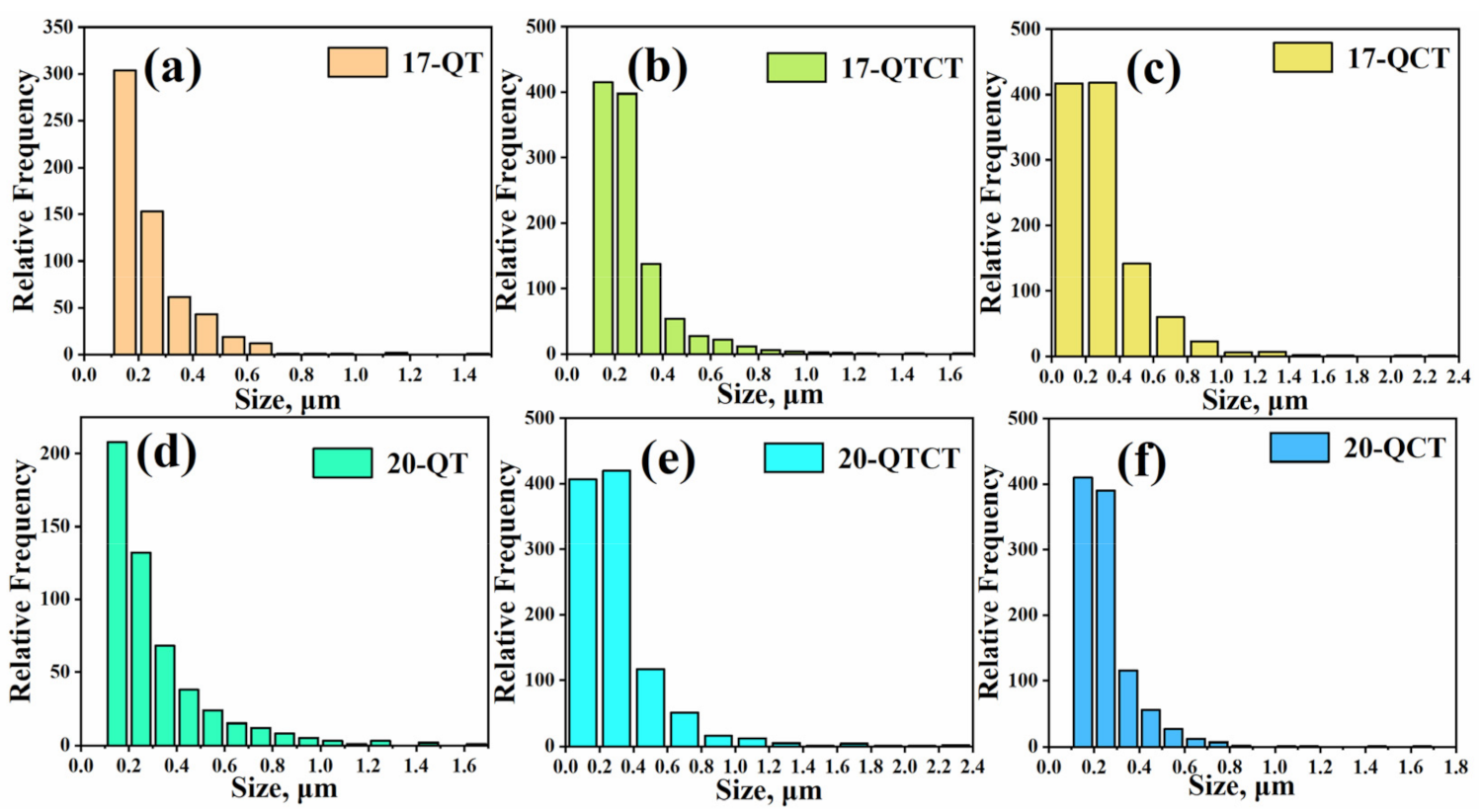
- The volume percentages of carbides obtained by the area percentage calculation of Image-pro software are 7.36% for 17-QT, 10.36% for 17-QTCT, 12.75% for 17-QCT, 6.17% for 20-QT, 9.2% for 20-QTCT, and 11.8% for 20-QCT.
- (3)
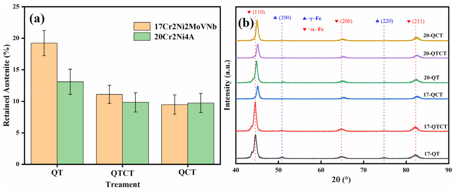
- The cryogenic treatment effectively decreased the retained austenite content, which was decreased from 13.1 to 9.5% (QTCT) and 9.6% (QCT) for 20Cr2Ni4A steel and from 19.23 to 10.7% (QTCT) and 9.15% (QCT) for 17Cr2Ni2MoVNb steel.
- (4)
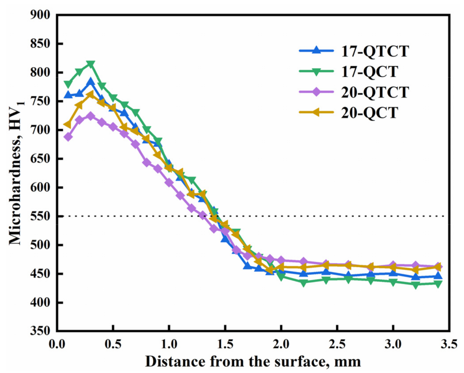
- The hardness of the samples near the surface after cryogenic treatment was increased by 102 HV for 17-QTCT and by 122 HV for 17-QCT compared with 17-QT, and it was increased by 13 HV for 20-QTCT and by 34 HV for 20-QCT compared with 20-QT.
- (5)
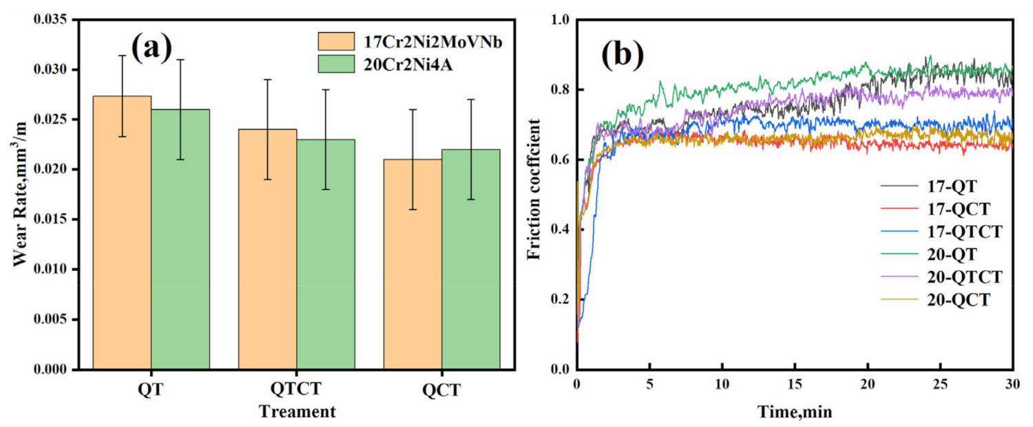
- The cryogenic treatment could effectively improve the wear resistance, and the wear rates of 17-QTCT and 17-QTC were decreased by 14.42% and 14.65%, respectively, and the wear rates of 20-QTCT and 20-QTC were decreased by 30.23% and 32.42%, respectively. The low temperature tempering sequence (QCT) in the cryogenic process had no effect on the wear resistance. The wear form of 17Cr2Ni2MoVNb steel was mainly composed of oxidation wear and adhesive wear, while the wear form of 20Cr2Ni4A steel was mainly composed of severe adhesive wear, abrasive wear, oxidation wear and a small amount of stress fatigue wear.
- (6)
- The distortion of the two experimental steels during the heat treatment and cryogenic treatment underwent shrinkage before expansion, and the distortion of 17Cr2Ni2MoVNb steel was smaller than that of 20Cr2Ni4A steel after heat treatment and cryogenic treatment.
Author Contributions
Funding
Institutional Review Board Statement
Informed Consent Statement
Data Availability Statement
Acknowledgments
Conflicts of Interest
References
- Wei, S.; Wang, G.; Zhao, X.; Zhang, X.; Rong, Y. Experimental Study on Vacuum Carburizing Process for Low-Carbon Alloy Steel. J. Mater. Eng. Perform. 2014, 23, 545–550. [Google Scholar] [CrossRef]
- Wang, Y.H.; Yang, Z.N.; Zhang, F.C.; Qin, Y.M.; Wang, X.B.; Lv, B. Microstructures and properties of a novel carburizing nano-bainitic bearing steel. Mat. Sci. Eng. Struct. 2020, 777, 139086. [Google Scholar] [CrossRef]
- Staśko, R.; Adrian, H.; Adrian, A. Effect of nitrogen and vanadium on austenite grain growth kinetics of a low alloy steel. Mater. Charact. 2006, 56, 340–347. [Google Scholar] [CrossRef]
- Kostoj, V.; Mithieux, J.D.; Fröhlich, T. Influence of Chromium Carbide Size on the Austenitization Kinetics of a Martensitic Stainless Steel Measured by Dilatometry. Solid State Phenom. 2011, 172–174, 426–431. [Google Scholar] [CrossRef]
- Bedekar, V.; Voothaluru, R.; Yu, D.; Wong, A.; Galindo-Nava, E.; Gorti, S.B.; An, K.; Hyde, R.S. Effect of nickel on the kinematic stability of retained austenite in carburized bearing steels—In-situ neutron diffraction and crystal plasticity modeling of uni-axial tension tests in AISI 8620, 4320 and 3310 steels0. Int. J. Plast. 2020, 131, 102748. [Google Scholar] [CrossRef]
- Kirchner, G.; Uhrenius, B. Experimental study of the ferrite/austenite equilibrium in the Fe-Cr-Mn system and the optimization of thermodynamic parameters by means of a general mathematical method. Acta Met. 1974, 22, 523–532. [Google Scholar] [CrossRef]
- Surberg, C.H.; Stratton, P.; Lingenhöle, K. The effect of some heat treatment parameters on the dimensional stability of AISI D2. Cryogenics 2008, 48, 42–47. [Google Scholar] [CrossRef]
- Huang, J.; Zhu, Y.; Liao, X.; Beyerlein, I.; Bourke, M.; Mitchell, T. Microstructure of cryogenic treated M2 tool steel. Mater. Sci. Eng. A 2003, 339, 241–244. [Google Scholar] [CrossRef]
- Bensely, A.; Senthilkumar, D.; Lal, D.M.; Nagarajan, G.; Rajadurai, A. Effect of cryogenic treatment on tensile behavior of case carburized steel-815M17. Mater. Charact. 2007, 58, 485–491. [Google Scholar] [CrossRef]
- Urica, J.; Ptainová, J.; Dománková, M.; Aplovi, L.; Juri, P. Changes in microstructure of ledeburitic tool steel due to vacuum austenitizing and quenching, sub-zero treatments at −140°C and tempering. Vacuum 2019, 170, 108977. [Google Scholar]
- Das, D.; Ray, K.; Dutta, A. Influence of temperature of sub-zero treatments on the wear behaviour of die steel. Wear 2009, 267, 1361–1370. [Google Scholar] [CrossRef]
- Jovičević-Klug, P.; Podgornik, B. Review on the Effect of Deep Cryogenic Treatment of Metallic Materials in Automotive Ap-plications. Metals 2020, 10, 434. [Google Scholar] [CrossRef] [Green Version]
- Zhang, Y.; Qu, S.; Lu, F.; Lai, F.; Ji, V.; Liu, H.; Li, X. Microstructures and rolling contact fatigue behaviors of 17Cr2Ni2MoVNb steel under combined ultrasonic surface rolling and shot peening. Int. J. Fatigue 2020, 141, 105867. [Google Scholar] [CrossRef]
- Zhang, Y.; Lai, F.; Qu, S.; Ji, V.; Liu, H.; Li, X. Effect of shot peening on residual stress distribution and tribological behaviors of 17Cr2Ni2MoVNb steel. Surf. Coat. Technol. 2020, 386, 125497. [Google Scholar] [CrossRef]
- Zhang, Y.-L.; Lai, F.-Q.; Qu, S.-G.; Liu, H.-P.; Jia, D.-S.; Du, S.-F. Effect of ultrasonic surface rolling on microstructure and rolling contact fatigue behavior of 17Cr2Ni2MoVNb steel. Surf. Coat. Technol. 2019, 366, 321–330. [Google Scholar] [CrossRef]
- Baldissera, P.; Delprete, C. Effects of deep cryogenic treatment on static mechanical properties of 18NiCrMo5 carburized steel. Mater. Des. 2009, 30, 1435–1440. [Google Scholar] [CrossRef]
- Song, L.; Gu, X.; Sun, F.; Hu, J. Reduced internal oxidation by a rapid carburizing technology enhanced by pre-oxidation for 18CrNiMo7-6 gear steel. Vacuum 2018, 160, 210–212. [Google Scholar] [CrossRef]
- Li, B.; Li, C.; Wang, Y.; Jin, X. Effect of Cryogenic Treatment on Microstructure and Wear Resistance of Carburized 20CrNi2MoV Steel. Metals 2018, 8, 808. [Google Scholar] [CrossRef] [Green Version]
- Jovievi-Klug, P.; Jovievi-Klug, M.; Podgornik, B. Effectiveness of deep cryogenic treatment on carbide precipitation. J. Mater. Res. Technol. 2020, 9, 13014–13026. [Google Scholar] [CrossRef]
- Wang, Y.; Zhang, F.; Yang, Z.; Bo, L.; Zheng, C. Rolling Contact Fatigue Performances of Carburized and High-C Nanostruc-tured Bainitic Steels. Materials 2016, 9, 960. [Google Scholar] [CrossRef] [PubMed] [Green Version]
- Putra, W.N.; Pramaditya, P.; Pramuka, P.; Mochtar, M.A. Effect of Sub Zero Treatment on Microstructures, Mechanical Properties, and Dimensional Stability of AISI D2 Cold Work Tool Steel. Mater. Sci. Forum 2018, 929, 136–141. [Google Scholar] [CrossRef]
- Jimbert, P.; Iturrondobeitia, M.; Ibarretxe, J.; Fernandez-Martinez, R. Influence of Cryogenic Treatment on Wear Resistance and Microstructure of AISI A8 Tool Steel. Metals 2018, 8, 1038. [Google Scholar] [CrossRef] [Green Version]
- Chen, W.; He, X.F.; Yu, W.C.; Shi, J.; Wang, M.Q.; Yao, K.F. Nano- and Microhardness Distribution in the Carburized Case of Nb-Microalloyed Gear Steel. J. Mater. Eng. Perform. 2020, 29, 4626–4630. [Google Scholar] [CrossRef]
- Magee, C.L. Phase Transformation; ASM: Metals Park, OH, USA, 1970; p. 115. [Google Scholar]
- Koistinen, D.; Marburger, R. A general equation prescribing the extent of the austenite-martensite transformation in pure iron-carbon alloys and plain carbon steels. Acta Metall. 1959, 7, 59–60. [Google Scholar] [CrossRef]
- Sobotova, J.; Jurci, P.; Dlouhy, I. The effect of subzero treatment on microstructure, fracture toughness, and wear resistance of Vanadis 6 tool steel. Mater. Sci. Eng. A 2016, 652, 192–204. [Google Scholar] [CrossRef]
- Graf, S.M. The effect of deep cold induced nano-carbides on the wear of case hardened components. Cryogenics 2009, 49, 176–184. [Google Scholar] [CrossRef]
- Amini, K.; Araghi, A.; Akhbarizadeh, A. Effect of Deep Cryogenic Heat Treatment on the Wear Behavior of Carburized DIN 1.7131 Grade Steel. Acta Met. Sin. Engl. Lett. 2015, 28, 348–353. [Google Scholar] [CrossRef]
- Bensely, A.; Prabhakaran, A.; Lal, D.M.; Nagarajan, G. Enhancing the wear resistance of case carburized steel (En 353) by cryogenic treatment. Cryogenics 2005, 45, 747–754. [Google Scholar] [CrossRef]
- Das, D.; Dutta, A.; Ray, K. Optimization of the duration of cryogenic processing to maximize wear resistance of AISI D2 steel. Cryogenics 2009, 49, 176–184. [Google Scholar] [CrossRef]
- Gong, W.; Chen, Y.; Li, M.; Kang, R. Coupling fractal model for adhesive and three-body abrasive wear of AISI 1045 carbon steel spool valves. Wear 2019, 418-419, 75–85. [Google Scholar] [CrossRef]
- Fabbro, S.; Araujo, L.M.; Engel, J.; Kondratiuk, J.; Kuffa, M.; Wegener, K. Abrasive and adhesive wear behaviour of metallic bonds in a synthetic slurry test for wear prediction in reinforced concrete. Wear 2021, 476, 203690. [Google Scholar] [CrossRef]
- Yan, X.; Li, D. Effects of the sub-zero treatment condition on microstructure, mechanical behavior and wear resistance of W9Mo3Cr4V high speed steel. Wear 2013, 302, 854–862. [Google Scholar] [CrossRef]
- Hardell, J.; Hernandez, S.; Mozgovoy, S.; Pelcastre, L.; Courbon, C.; Prakash, B. Effect of oxide layers and near surface transformations on friction and wear during tool steel and boron steel interaction at high temperatures. Wear 2015, 330–331, 223–229. [Google Scholar] [CrossRef]
- Iakovakis, E.; Roy, M.J.; Gee, M.; Matthews, A. Evaluation of wear mechanisms in additive manufactured carbide-rich tool steels. Wear 2020, 462-463, 203449. [Google Scholar] [CrossRef]
- Cheng, X.; Jiang, Z.; Wei, D.; Wu, H.; Jiang, L. Adhesion, friction and wear analysis of a chromium oxide scale on a ferritic stainless steel. Wear 2019, 426–427, 1212–1221. [Google Scholar] [CrossRef]
- Peng, W.; Sun, K.; Zhang, M.; Chen, J.; Shi, J. Effects of Deep Cryogenic Treatment on the Microstructures and Tribological Properties of Iron Matrix Self-Lubricating Composites. Metals 2018, 8, 656. [Google Scholar] [CrossRef] [Green Version]
- Zhang, J.; Tan, W.; Wang, C.; Zhu, C.; Yi, Y. Cryogenic Deformation Behavior and Microstructural Characteristics of 2195 Al-loy. Metals 2021, 11, 1406. [Google Scholar] [CrossRef]
- Graf, M.; Ullmann, M.; Korpala, G.; Wester, H.; Awiszus, B.; Kawalla, R.; Behrens, B.-A. Forming and Oxidation Behavior Dur-ing Forging with Consideration of Carbon Content of Steel. Metals 2018, 8, 996. [Google Scholar] [CrossRef] [Green Version]


| Steel | C | Si | Mn | Cr | Ni | Mo | Nb | V | Fe |
|---|---|---|---|---|---|---|---|---|---|
| 20Cr2Ni4A | 0.21 | 0.25 | 0.48 | 1.45 | 3.55 | - | - | - | Bal. |
| 17Cr2Ni2MoVNb | 0.17 | ≤0.4 | 0.77 | 1.68 | 1.60 | 0.29 | 0.04 | 0.10 | Bal. |
| Steel | Sample Code | Description of Heat Treatment Cycles | |||
|---|---|---|---|---|---|
| Quenching | Temperature | Cryogenic Treatment | Temperature | ||
| 20Cr2Ni4A | 20-QT | 800 °C, 1 h | 150 °C, 4 h | -- | -- |
| 20-QTCT | 800 °C, 1 h | 150 °C, 4 h | −196 °C, 1 h | 150 °C, 2 h | |
| 20-QCT | 800 °C, 1 h | -- | −196 °C, 1 h | 150 °C, 2 h | |
| 17Cr2Ni2MoVNb | 17-QT | 800 °C, 1 h | 150 °C, 4 h | -- | -- |
| 17-QTCT | 800 °C, 1 h | 150 °C, 4 h | −196 °C, 1 h | 150 °C, 2 h | |
| 17-QCT | 800 °C, 1 h | -- | −196 °C, 1 h | 150 °C, 2 h | |
Publisher’s Note: MDPI stays neutral with regard to jurisdictional claims in published maps and institutional affiliations. |
© 2021 by the authors. Licensee MDPI, Basel, Switzerland. This article is an open access article distributed under the terms and conditions of the Creative Commons Attribution (CC BY) license (https://creativecommons.org/licenses/by/4.0/).
Share and Cite
Yan, Y.; Liu, K.; Luo, Z.; Wang, M.; Wang, X. Effect of Cryogenic Treatment on Microstructure, Mechanical Properties and Distortion of Carburized Gear Steels. Metals 2021, 11, 1940. https://doi.org/10.3390/met11121940
Yan Y, Liu K, Luo Z, Wang M, Wang X. Effect of Cryogenic Treatment on Microstructure, Mechanical Properties and Distortion of Carburized Gear Steels. Metals. 2021; 11(12):1940. https://doi.org/10.3390/met11121940
Chicago/Turabian StyleYan, Yongming, Ke Liu, Zixiang Luo, Maoqiu Wang, and Xinming Wang. 2021. "Effect of Cryogenic Treatment on Microstructure, Mechanical Properties and Distortion of Carburized Gear Steels" Metals 11, no. 12: 1940. https://doi.org/10.3390/met11121940
APA StyleYan, Y., Liu, K., Luo, Z., Wang, M., & Wang, X. (2021). Effect of Cryogenic Treatment on Microstructure, Mechanical Properties and Distortion of Carburized Gear Steels. Metals, 11(12), 1940. https://doi.org/10.3390/met11121940