Article

Numerical Investigation of Flow Characteristics of Molten Steel in the Tundish with Channel Induction Heating

1
School of Materials and Metallurgy, University of Science and Technology Liaoning, Anshan 114051, China
2
Key Laboratory of Electromagnetic Processing of Materials, Ministry of Education, Northeastern University, Shenyang 110819, China
3
School of Metallurgy, Northeastern University, Shenyang 110819, China
4
Angang Steel Corporation Limited, Anshan 114000, China
*
Author to whom correspondence should be addressed.
Metals 2021, 11(12), 1937; https://doi.org/10.3390/met11121937
Submission received: 8 October 2021 / Revised: 30 October 2021 / Accepted: 22 November 2021 / Published: 30 November 2021
(This article belongs to the Special Issue Thermodynamics and Kinetics in Metallurgical Processes)

Abstract

:
In the continuous process, fluid flow is an important physical phenomena in the tundish, as it affects the process of heat transfer, bubble motion and inclusion collision-coalescence and grow up. This paper undertakes a detailed numerical investigation of fluid flow characteristics in the tundish with and without induction heating. The individual unit method and the volume subtraction model are applied to analyze the flow characteristics. A quantitative evaluation method of flow characteristics is proposed to investigate the flow characteristics. In the tundish with and without induction heating, firstly, the main flow behavior of molten steel is mixed flow in the receiving chamber; secondly, the main flow behavior of molten steel is plug flow in the channel; lastly, the main flow pattern is mixed flow, and the minor flow pattern is plug flow in the discharging chamber. The method of the volume subtraction model is an effective way to analyze the flow characteristics in the tundish with channel induction heating.

1. Introduction

Tundish metallurgy has assumed considerable importance and, accordingly, many innovations were systematically introduced in the academic steelmaking area [1,2,3]. This progressive demand for high-quality steel has prompted more researchers to more closely evaluate the different steps in the tundish metallurgy process, where it is possible to facilitate the removal of inclusions in molten steel [4,5,6,7,8,9,10]. Many complex metallurgical processes and phenomena, such as high temperature, chemical reaction, electromagnetic field, visual opacity, etc. will be inconvenient and dangerous to directly measure or undertake physical experiment research in continuous casting equipment. With the availability and practicability of less expensive high-performance computers, mathematical modeling, along with physical modeling, has become a reasonable alternative route for investigating fluid-dynamic behavior in the tundish. The fluid flow behavior in the tundish using physical and mathematical modeling have been investigated in the published literatures [11,12,13,14,15,16]. Previous studies have shown the influence of the shapes, operating parameters, flow control devices (dam, weir, slotted baffles with inclined holes, turbulence inhibitors), gas injection in conjunction with flow modifiers on macroscopic fluid transport behavior, etc. [17,18,19,20,21,22,23,24,25,26,27,28]. The important flow behavior of tundish which would help to achieve better performance of the tundish with respect to inclusion separation and float out, minimum dead volume, large ratio of plug to dead volume, relatively large ratio plug to mixed volume and the maximum average residence time.
For the tundish with channel type induction heating, due to its convenient heating function, excellent stirring effect and novel structure in modern metallurgical industry, an increasing number of steel mills have carried out industrial production. Research on a multi-physical field (electromagnetic field, flow field, temperature field and inclusion field) has been investigated in recent years [29,30,31,32,33,34,35,36,37]. So far, the detailed flow behavior of the fluid in the channel-type induction heating tundish is still a vague concept, which the unknown plug volume, dead volume and mixed volume in the receiving chamber, channel and discharging chamber.
To predict the performance of tundish with channel induction heating, the numerical simulation of residence time distribution (RTD) curve is carried out to analyze the hydrodynamic behavior of molten steel. The main objective of this work is to build a mathematical modeling and an analytical method frame work that can be used to predict tundish performances with particular structure through the calculated dead zone or low velocity zone (three-dimensional cloud map).
In summary, in order to fulfill the main objective of this work, the following simulations were carried out: (1) the flow characteristics in the tundish with channel type involves in the coupling calculation of electromagnetic field, flow field and temperature field is analyzed, (2) an analysis method is proposed to analyze flow characteristics for combined metallurgical vessels, (3) evaluation of the analytical method on RTD.

2. Model Development

2.1. Geometrical Description

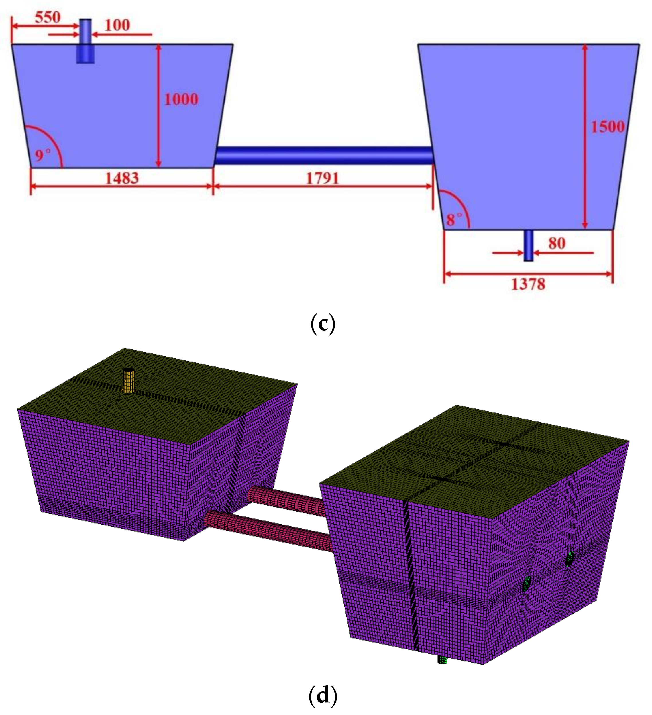
Simulation is performed for the tundish with channel type induction heating, Figure 1 shows the geometric parameter and mesh of the tundish with channel type induction heating. Table 1 shows the operating and geometry parameters of the tundish, and the physical parameters of molten steel.

2.2. Governing Equations

To solve the magneto-hydrodynamics of system, a set of Maxwell’s equations and Navier–Stokes equations were used:
Magnetic field constitutive equation:
1 μ × A + σ A t + φ = 0
× 1 μ × A = J s
A = 0
Continuity equation:
ρ f t + ( ρ f u f ) = 0
Momentum equation:
( ρ f u f ) t + ρ f u f u f = P + ρ f g + β ( T 0 T ) ρ f g + [ μ eff ( u f + ( u f ) T ) ] + J × B
Turbulent kinetic energy and Rate of dissipation:
( ρ f κ ) t + ( ρ f κ u f ) x j = x j ( μ + u t σ k ) κ x j + G k ρ f ε
( ρ f ε ) t + ( ρ f ε u j ) x j = x j ( μ + u t σ ε ) ε x j + C 1 ε ε κ G κ C 2 ε ρ f ε 2 κ
Energy conservation equation:
ρ c P T t + ρ f T u = λ T + σ J 2
Tracer transport equation:
ρ f C t + ρ f u f C = D e f f . C
where A is the magnetic vector potential, ϕ is the electric scalar potential ϕ , σ is the electrical conductivity, J s is the source currents, μ is the magnetic conductivity, μ eff is the effective viscosity, ρ f is the fluid density, u f is the fluid velocity, P is the pressure, g is the gravitational accelerate, κ is the turbulence kinetic energy, ε is the turbulent kinetic energy rate, σ κ and σ ε represent the Schmidt number for κ and ε , G k is the generation rate of turbulence energy, C p is the heat capacity, T is the temperature, C is the mass fraction of the injected tracer.
The constants of the κ ε two-equation turbulence model are taken as: C1 = 1.44, C2 = 1.92, σ κ =1.0, σ ε = 1.3.

2.3. Assumptions

The assumptions for electromagnetic field, flow and heat transfer in the tundish with channel induction heating have already been published in previous papers [32,34,35]. The current model is applied for the present work. The RTD curve analysis model is shown in Table 2. Some simple assumptions are as follows:
(1)
The flow of molten steel in the tundish is at the steady state.
(2)
There is only the physical behavior in the tundish.
(3)
The physical parameter of the tracer is the same as molten steel in the tundish.
Where the t ¯ is the mean residence time, t 0 is the theoretical residence time, t min is the minimum residence time, t max is the peak concentration time, v is the volume of tundish, q is the volumetric flow rate, V d is the dead volume, V m is mixed volume, V p is plug volume, τ is the dimensionless time.

2.4. Boundary Conditions

In the air sphere, the magnetic flux lines were closed, so the magnetic flux was parallel to the boundary at the side of air sphere, and it satisfies a Neumann boundary condition on the surfaces of the air sphere [34].
Free-slip condition was set for the free surface, no-slip condition was set for others walls of the tundish and the standard wall function was used to incorporate the variation due to turbulence. Inlet velocity and the heat flux at the free surface and the tundish walls are mentioned in Table 3. Pressure boundary condition of 1atm was fixed at the outlets of the tundish [35]. A zero gradient or flux boundary condition was applied for the tracer concentration on the walls, free surface and outlets for the tracer dispersion equation.

2.5. Numerical Procedure

The CFD commercial preprocessor ANSYS-EMAG module was used to solve the Maxwell’s equations, ICEM was used to build the model tundish with channel induction heating, CFX14.5 was used to solve the Navier–Stokes equations, and the tracer dispersion equation was used to solve unsteady state with momentum and turbulence equations to get the RTD curve. Post processing of the results was carried out using TECPLOT 2011. The domain was divided into 300,318 hexahedral cells. During iteration, the convergence was assumed to reach a point where all the normalized residuals are smaller than 10 6 [32,35].

3. Validation of Numerical Results

3.1. Grid Independence

In order to ensure the accuracy and reliability of the numerical result, a grid sensitivity test was carried out on the flow field calculation case. In this case, the inlet velocity is 0.5 m / s . The grid system consists of 196,156, 248,300, 300,318, 324,848 and 350,580 grids.
Table 4 gives the related analysis result of test point M (x = 0.39, y = 2.51, z = 0.9). From the mesh 196,156 to 350,580, the variation of velocity value is on the third digit (the maximum related error is only 1.12%). Therefore, the 300,318 mesh can be applied to obtain the RTD curves.

3.2. Model Validation

The model validation about fluid flow, temperature field, electromagnetic force and inclusion field can be found in previous papers [32,34,35]. The experimental device of the water model is also described in the paper [35].
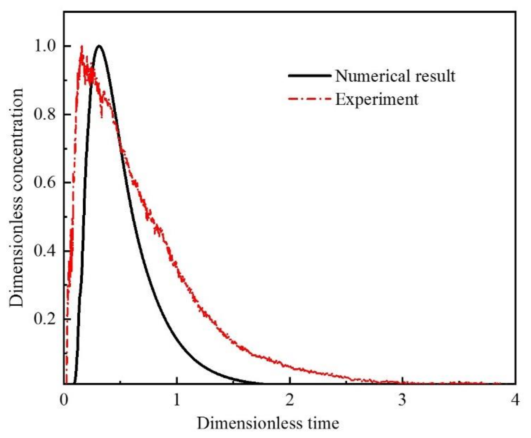
Figure 2 and Table 5 give the RTD curve and the fluid flow characteristic in the water model and simulation calculation. The relative error is less than 5%, which the predicted result agrees with the experimental data of water model.

4. Results and Discussion

4.1. Investigation of the Fluid Flow Characteristics by Individual Unit Method

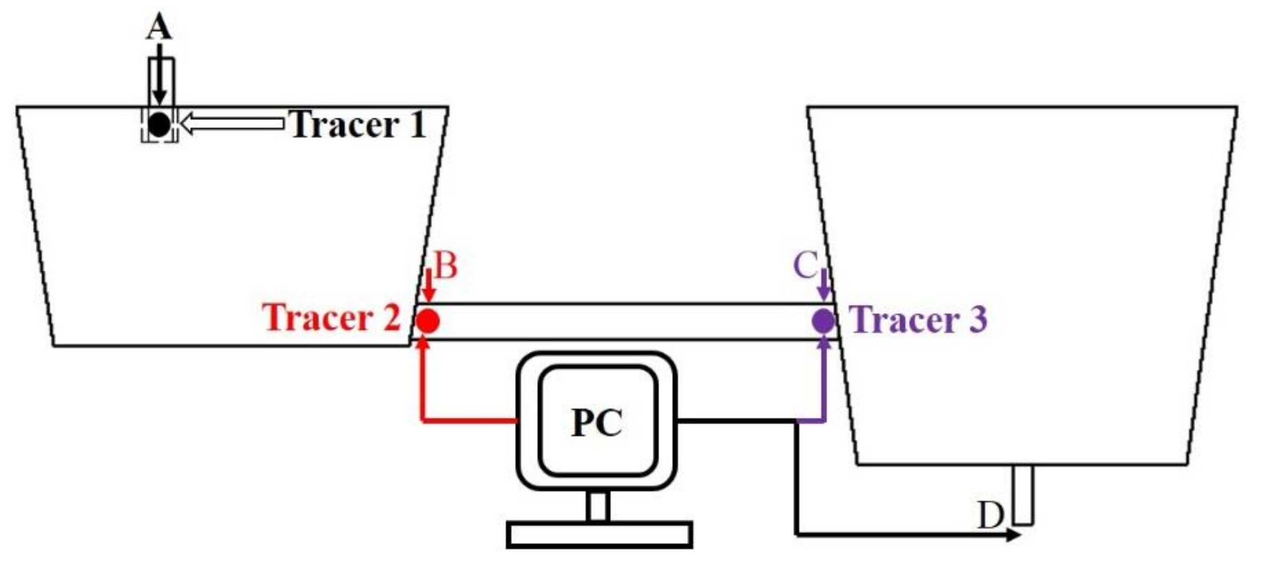
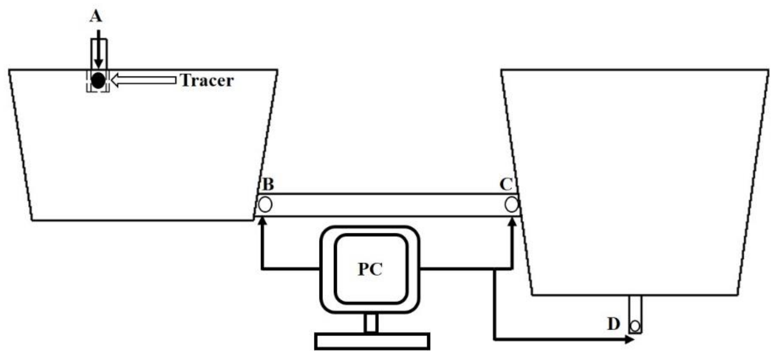
Figure 3 and Table 6 show the simple structure diagram of the RTD measurement method that the tracer 1 is added at point A (ladle shroud), the monitor location is point B (inlet of channel), the obtained curve is applied to investigate the flow characteristic of molten steel in the receiving chamber, based on the above method, tracer 2 is added at point B (inlet of channel), the monitor location is point C (outlet of channel), the obtained curve is applied to investigate the flow characteristic of molten steel in the channel, and tracer 3 is added at point C (outlet of channel), the monitor location is point D (outlet of tundish), the obtained curve is applied to investigate the flow characteristic of molten steel in the discharging chamber.
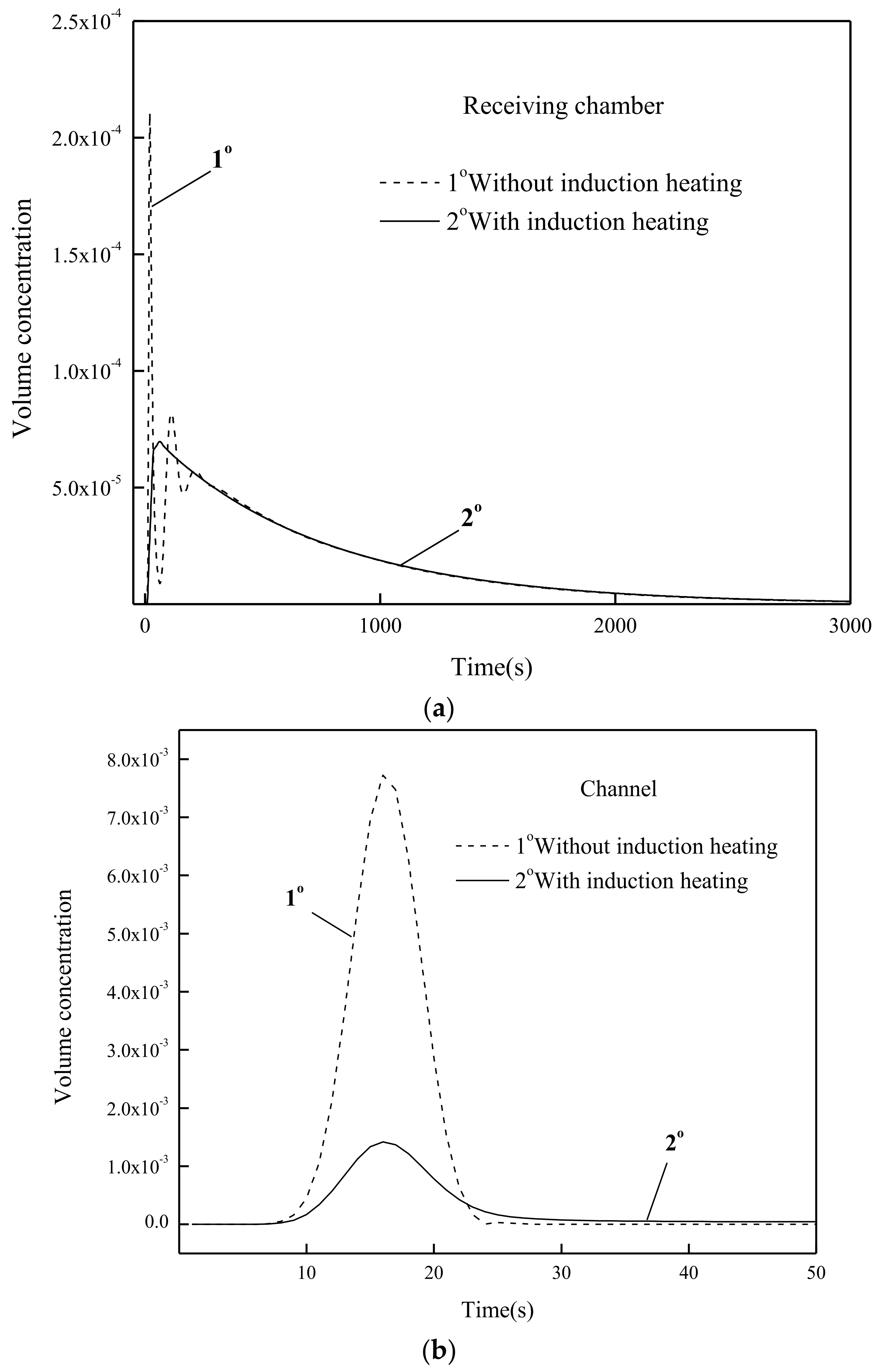
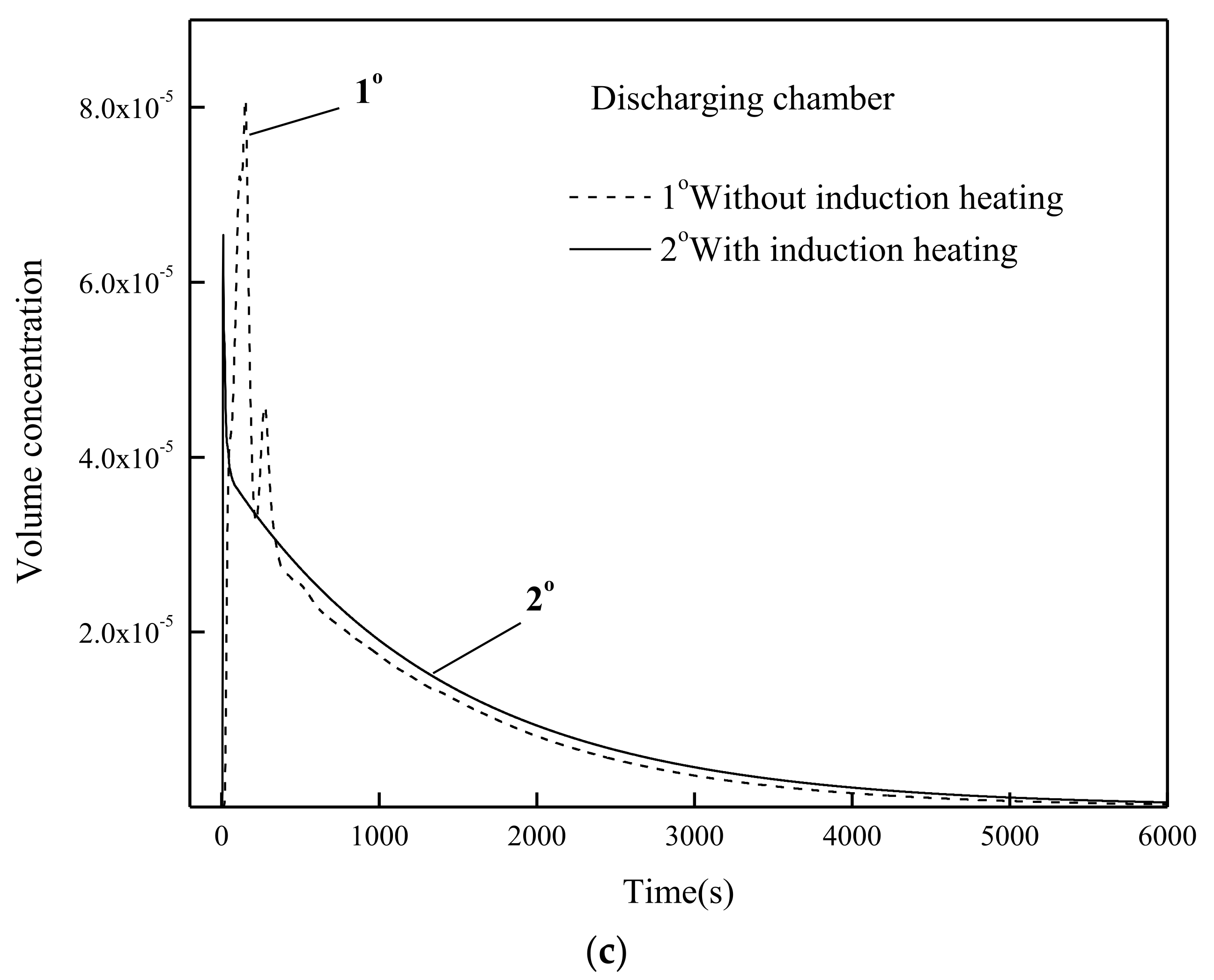
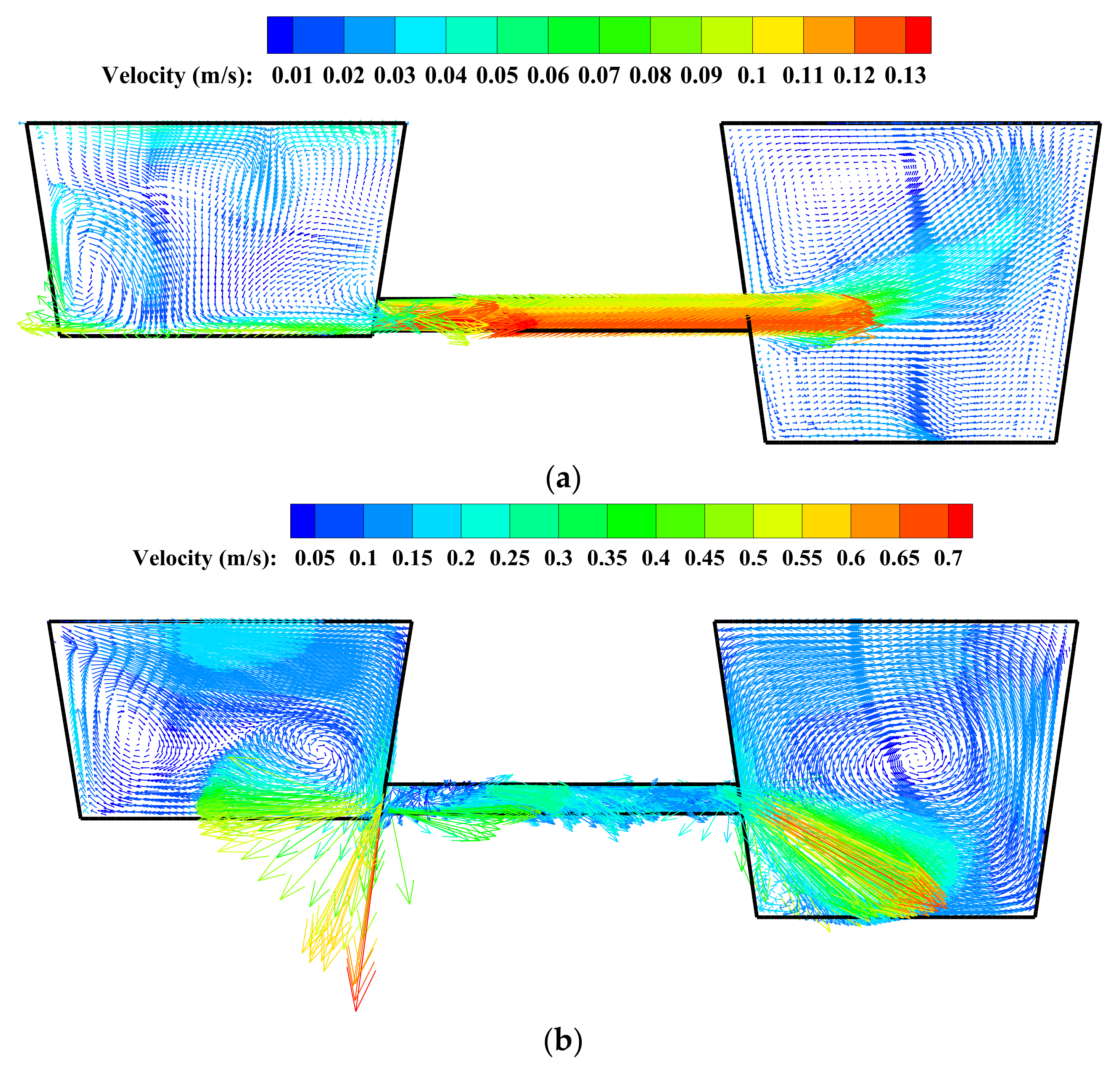
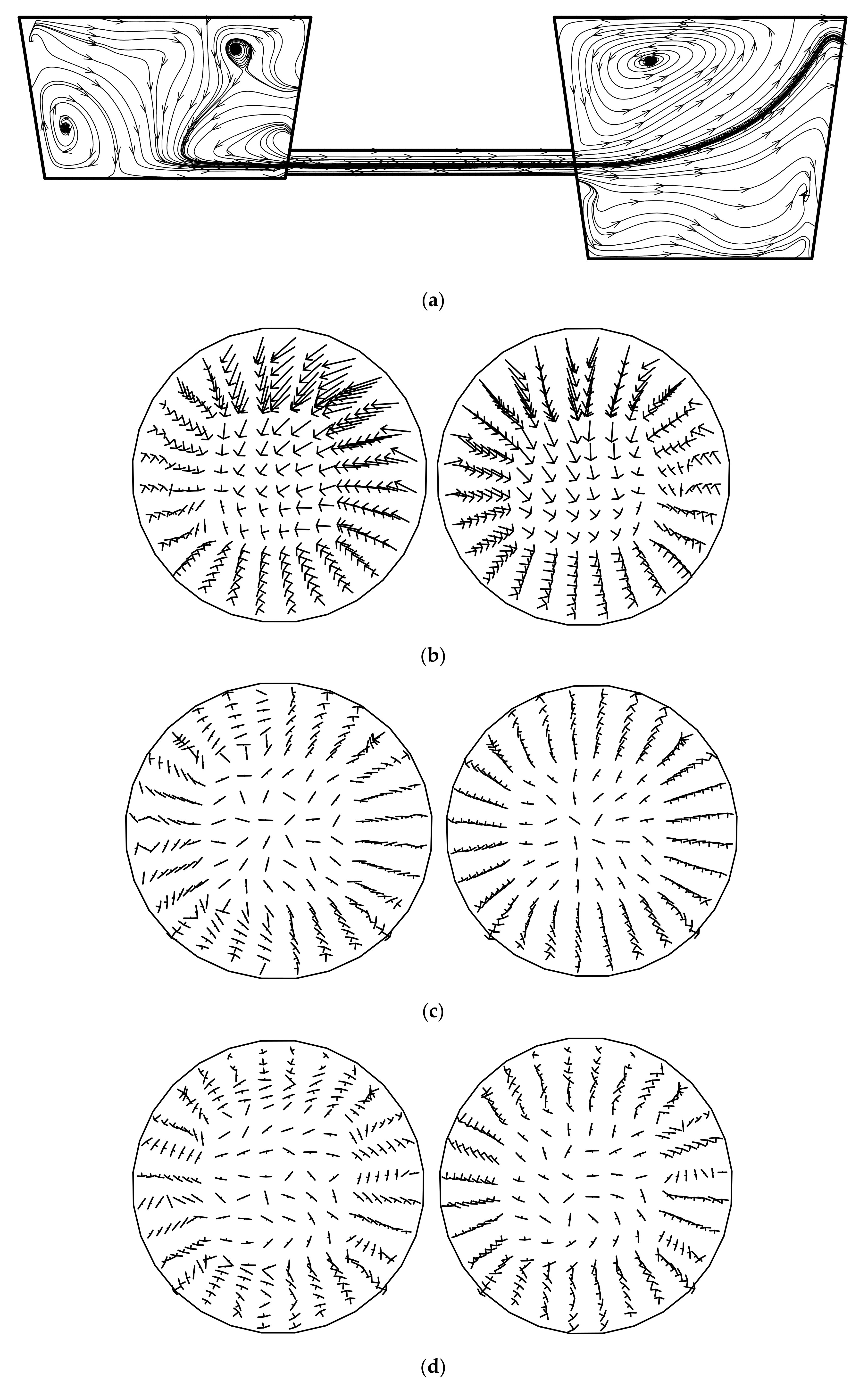
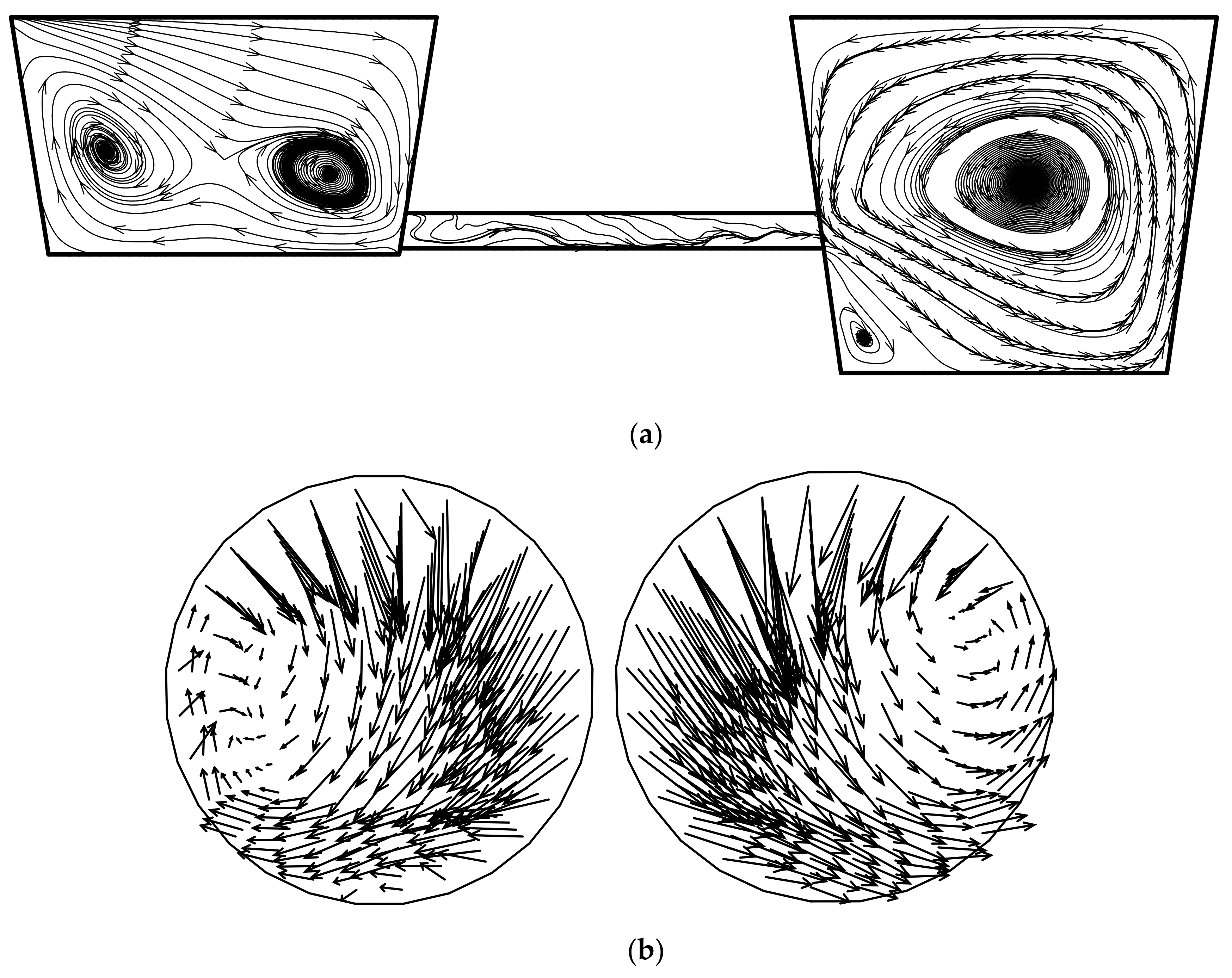
The RTD curves in the receiving chamber, channel and the discharging chamber with and without induction heating respectively can be seen from Figure 4, some important characteristics need to be explained. (1) In the case of without induction heating, the sharp rise in the multiple peak concentration reflects the presence of short circuiting in the receiving chamber. The reason for this phenomena can be explained by analyzing the fluid flow behavior in the tundish. Figure 5 shows the flow pattern for vertical plane cross the channel for the tundish. The fluid flow into the inlet of channel mainly comes from three different regions at different times, the main flow comes from ladle shroud directly, the minor flow comes from the circulation loop, the weaker flow comes from the area above the channel, and the tracer will be dispersed in the receiving chamber at a slow speed. (2) In the case of induction heating, the short circuiting phenomena has all but disappeared in the receiving chamber and discharging chamber, and the reason for this can be attributed to the two intense circulation loops in the receiving chamber and a huge circulation loop with a high speed as shown in Figure 5b. (3) Figure 4b shows that the time to attain the peak concentration is very close to the half of the residence time (50% of residence time) for the channel. Thus, the curve shape reflects the large amount of fluid elements that seem to be in plug flow in the channel.
Table 7 shows the fluid flow characteristics by individual unit method for the two conditions. Some noteworthy information is expressed as follows: (1) In the case of without induction heating, the residence time of molten steel are 544.4 s, 16.2 s and 907.4 s in the receiving chamber, channel and discharging chamber respectively. In the case of induction heating, the residence times of molten steel are 547.2 s, 17.5 s and 996.8 s. The large recirculation zone will increase the flow path for molten steel and will improve the mixing effect in the discharging chamber and the temperature of molten steel will become more uniform in the discharging chamber [34]. This phenomenon of recirculate flow will enhance the mixed volume and increase the inclusion collision-coalescence and grow up [32]. (2) In the receiving chamber without induction heating, the mixed volume is 2.075 m 3 , it occupies 73.4% of the volume; the plug volume is 0.063 m 3 , it occupies 2.2% of the volume; the dead zone volume is 0.688 m 3 , it occupies 24.3% of the volume. In the receiving chamber with induction heating, the mixed volume is 2.004 m 3 , it occupies 70.9% of the volume; the plug zone volume is 0.145 m 3 , it occupies 5.1% of the volume; the dead zone volume is 0.677 m 3 , it occupies 24.0% of the volume. The two results show that the main flow behavior of molten steel is mixed flow in the receiving chamber. (3) In the channel, it can be found that the dead zone volume are −0.003 m 3 and −0.007 m 3 , respectively, for two cases. Although the value is negative, but it is close to zero, it may be caused by numerical errors. For case 1 and case 2, the two results of plug volumes have the same result, with a value of 0.051 m 3 , accounting for 83.6% of the channel volume. The result shows that the main flow of molten steel in the channel is plug flow. (4) In the discharging chamber, the mixed volume are 3.218 m 3 and 3.879 m 3 respectively, it occupies the 61.36% and 73.97% of volume. The numerical result shows that the main flow behavior of molten steel is mixed flow in the discharging chamber.

4.2. Investigation of the Fluid Flow Characteristics by Volume Subtraction Model

Figure 6 and Table 8 show the measurement method of the volume subtraction model for investigating the fluid flow characteristics. The details of the measurement method are described as follows, the tracer is added at the ladle shroud, and the monitor points are at point B (inlet of channel), point C (outlet of channel) and point D (outlet of tundish) respectively, the three monitor points can obtain three RTD curves which are applied to analyze the flow characteristic. In this method, some abbreviations and symbols need to be explained, V A B represents the volume of the receiving chamber; V A C represents the total volume of receiving chamber and channel; V A D represents the volume of the whole tundish. The V A B p l u g , V A B m i x , V A B d e a d represent the plug volume, mixed volume and dead volume in the receiving chamber, V A C p l u g , V A C m i x , V A C d e a d represent the plug volume, mixed volume and dead volume in the combined chamber (receiving chamber + channel), V A D p l u g , V A D m i x , V A D d e a d represent the plug volume, mixed volume and dead volume in the tundish. In order to investigate the flow characteristic in the channel and discharging chamber, the volume subtraction method which is the hysteresis measured data minus the previous measuring data. Described as a simple mathematical expression, the V A C p l u g V A B p l u g = V C h a n n e l p l u g , V A C m i x V A B m i x = V C h a n n e l m i x , and V A C d e a d V A B d e a d = V C h a n n e l d e a d represent the plug volume, mixed volume and dead volume respectively in the channel, V A D p l u g V A C p l u g = V D i s c h arg i n g c h a m b e r p l u g , V A D m i x V A C m i x = V D i s c h arg i n g c h a m b e r m i x , and V A D d e a d V A C d e a d = V D i s c h arg i n g c h a m b e r d e a d represent the plug volume, mixed volume and dead volume respectively in the discharging chamber. Meanwhile, the same way is applied to get the information in the channel and discharging chamber. To facilitate reading, V B C O and V C D O represent the general terms of volume after subtracting.
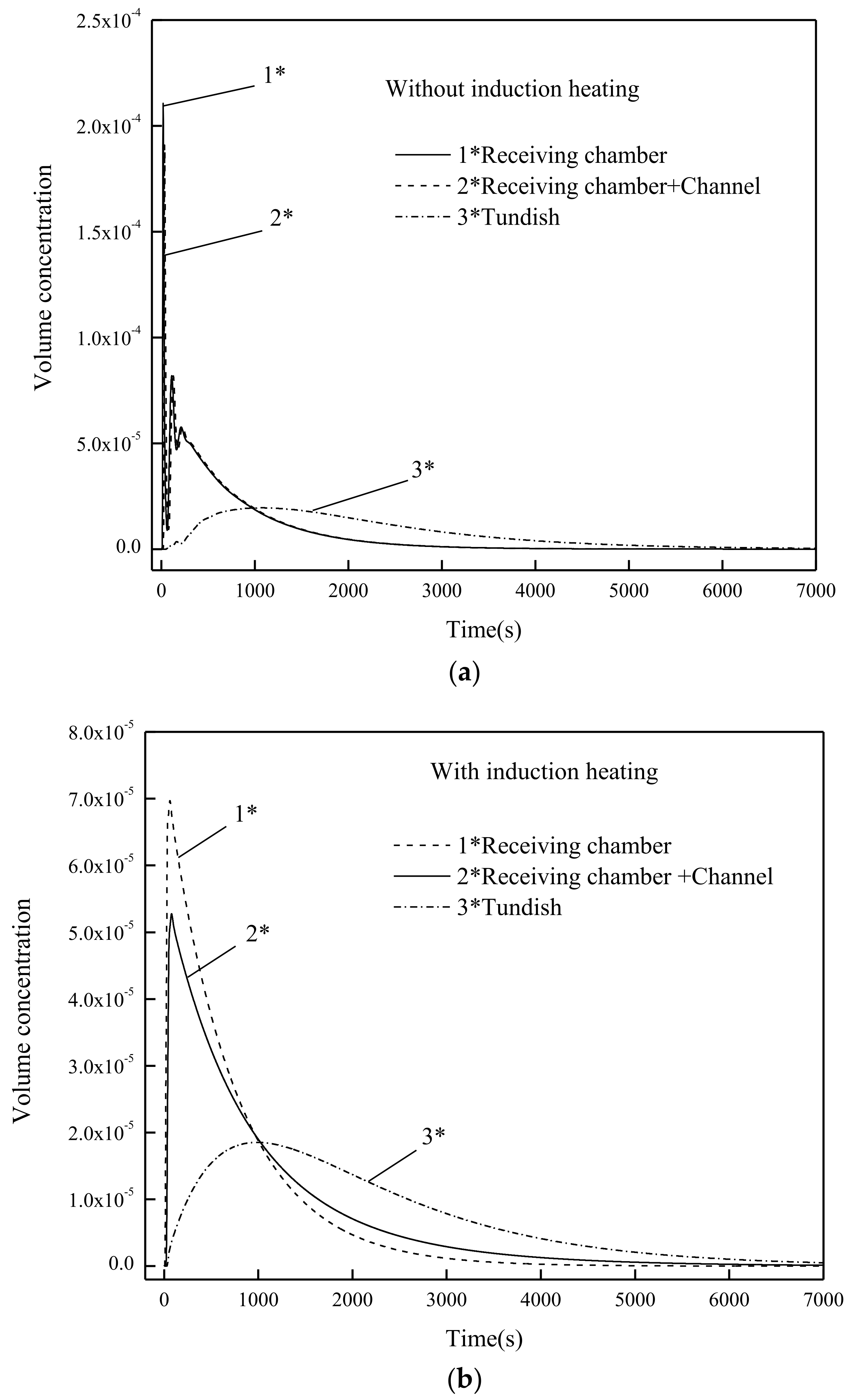
The RTD curve for the tundish with and without channel induction heating can be seen from Figure 7. Figure 7a shows that the sharp rise in the peak concentration reflects the presence of short circuiting in the receiving chamber, combined chamber and the whole tundish, and it means the large amount of molten steel appears to have less time to mix and the mixing effects are out of sync. The further the position of the monitoring point, the weaker multiple peak phenomena. The multiple peak phenomena disappears in Figure 7b, and this is because the strong stirring phenomena as shown in the receiving chamber, channel and discharging chamber, and the fluid movement in the tundish with induction heating is quite intense as compared to the tundish without induction heating, as shown in the Figure 8 and Figure 9.
The analytical results were obtained by volume subtraction model can be seen from Table 9. It can be seen that the mixed volume and the dead volume are 0.236 m 3 and −0.241 m 3 , the calculated value violates conventional results in theory. This is because the RTD curve describes the mixed condition of tracer in the direction of fluid flow, simply put, it is the characteristic of flow in one-dimensional space. But in the tundish with channel induction heating, the strong circumferential movement and strong axial movement in the channel will cause a great error by using the RTD curve to describe the flow characteristic.
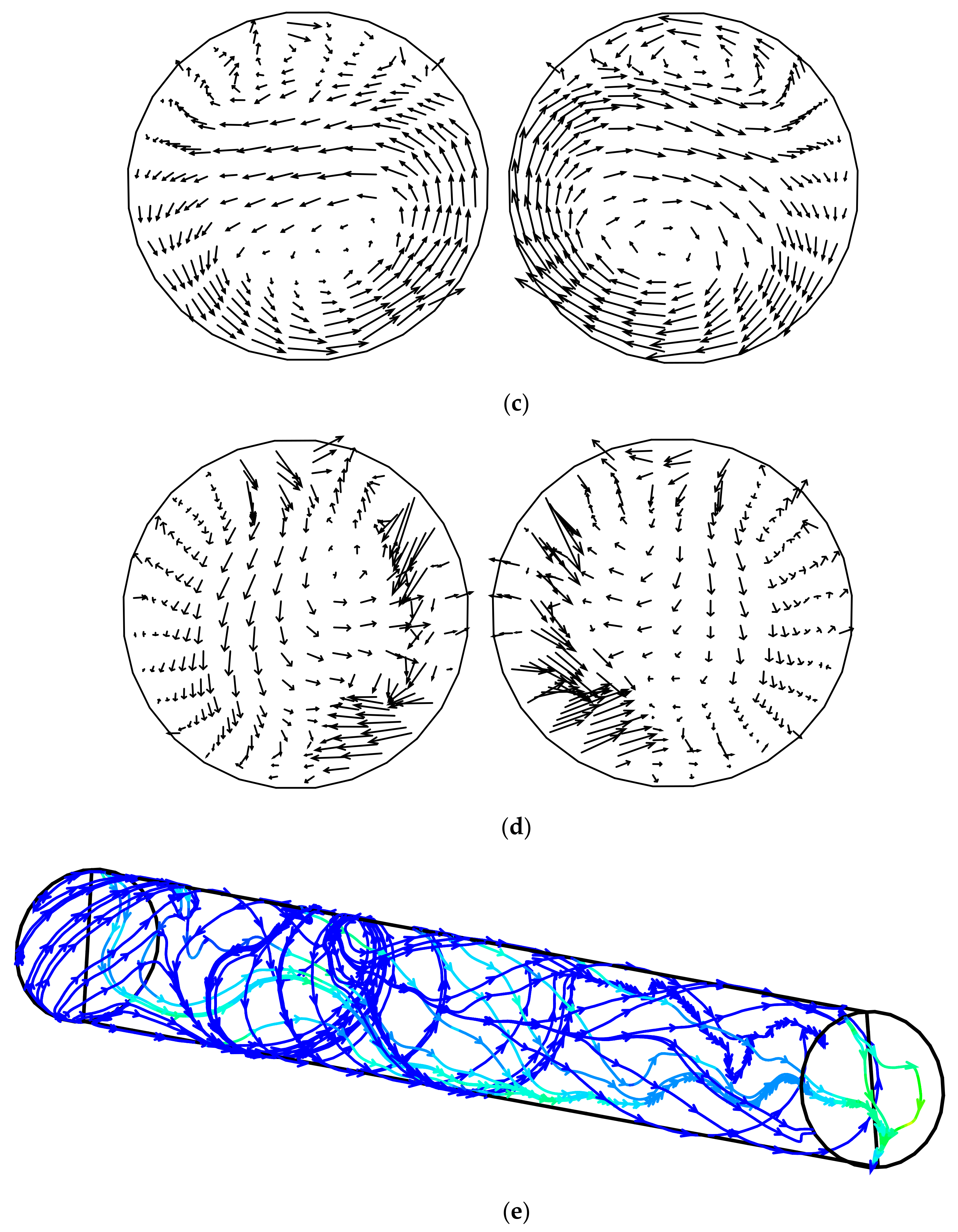
Therefore, comparing flow field distribution and RTD curve result data is an optimal solution to analyze the flow characteristic in the receiving chamber, channel and discharging chamber in the tundish with channel type. Some noticeable information is as follows. (1) The fluid flow behavior in the receiving chamber is the same with Table 8 due to the same monitor point. (2) The mean residence time of 76.3 s in the channel with induction heating is 57 s greater than the mean residence time of 19.3 s in the channel without induction heating. The difference of mean residence between Table 7 and Table 9 is very large, the reason for the discrepancy can be attributed to the fluid behavior in the channel. Figure 8 and Figure 9 show the flow pattern for the vertical plane (YZ) of the tundish. The spiral flow can be visualized in the channel, and the results also show that the backflow occurred at the inlet of the channel and center region of the channel due to the great electromagnetic force. In the Table 7, the tracer is added at inlet of channel, the backflow has little effect on the solute transport, but when the tracer is added at ladle shroud, the calculation result is totally different absolutely due to the complex fluid behavior at the inlet of channel as shown in the Figure 9. The fluid flow is a developed pipe flow in the channel without induction heating as shown in Figure 8. (3) In the channel without induction heating, the plug zone volume is 0.0589 m 3 , it occupies 96.6% of the volume, and the plug zone volume is 0.0609 m 3 in the channel with induction heating, it occupies 99.8% of the volume, a comparison of the plug volume in the Table 7 and Table 9 show that the difference of plug volume between two methods is less than 20%, therefore, the main flow in the channel is plug flow, and dead volume can be considered as zero due to the developed pipe flow and spiral flow in the channel, as shown in Figure 8 and Figure 9. (4) In the discharging chamber with and without induction heating, the mean residence time are 1286.4 s and 1188.6 s, the difference of time is 97.8 s. This is because the flow speed of molten steel in the discharging chamber is higher as compared to that without induction heating, as can be noticed from Figure 5. (5) In the discharging chamber without induction heating, the mixed volume and plug volume are 2.933 m 3 and 2.118 m 3 respectively, it occupies 57.1% and 40.4% of the volume. The mixed zone volume and plug zone volume are 2.84 m 3 and 1.822 m 3 respectively in the discharging chamber with induction heating, it occupies 54.2% and 34.7% of the volume. Therefore, the main flow pattern is mixed flow, and the minor flow pattern is plug flow. The two flow patterns dominate the main flow behavior in the discharging chamber.

4.3. Investigation of the Flow Characteristics in the Tundish with Channel Induction Heating

The RTD curve is an effective method to evaluate the flow characteristic of molten steel in the tundish, and the dead volume, plug volume and mixed volume can be obtained. The result shows that the traditional quantitative research on flow characteristics in conventional tundish is still mainly based on the RTD curve which typically, an appropriate tracer is injected into the liquid passing through the ladle shroud at time. The concentration of the added tracer is monitored dynamically at the exit nozzle of the tundish, whether single-strand, two-strand or multi-strand tundish. In this paper, the volume subtraction method is applied to quantitatively evaluate the flow characteristics of molten steel in the tundish with channel induction heating. In this paper the biggest difference from a previous study is that, two dead region critical velocity standards are used to evaluate the flow behavior, which is simply expressed one dead region critical velocity u d 1 in the receiving chamber is applied to evaluate the dead region in the receiving chamber, another dead region critical velocity u d 2 is applied to evaluate the dead region in the discharging chamber. It seems inappropriate to use a single dead region critical velocity standard to evaluate the flow characteristics in such a combined metallurgical container. The reason for this can be attributed to the fact that if the volume of chamber A is much larger than the volume of chamber B, a slow flow area mainly appears in the chamber A, a fast flow area appears in the chamber B based on previous research results, the dead zone mainly appears in the volume chamber A, this method lacks credibility for a combined metallurgical reactor.
Based on the above analysis, this study defines the dead zone in the receiving chamber and discharging chamber as the area where the speed is less than a certain critical speed in each chamber. The certain critical velocity u d 1 and u d 2 are defined in the receiving chamber and discharging chamber respectively, and dead area in the tundish can be observed clearly. For the tundish with channel type, the dead region volume at different critical velocity can be determined by mathematical derivation and CFD-POST statistics.
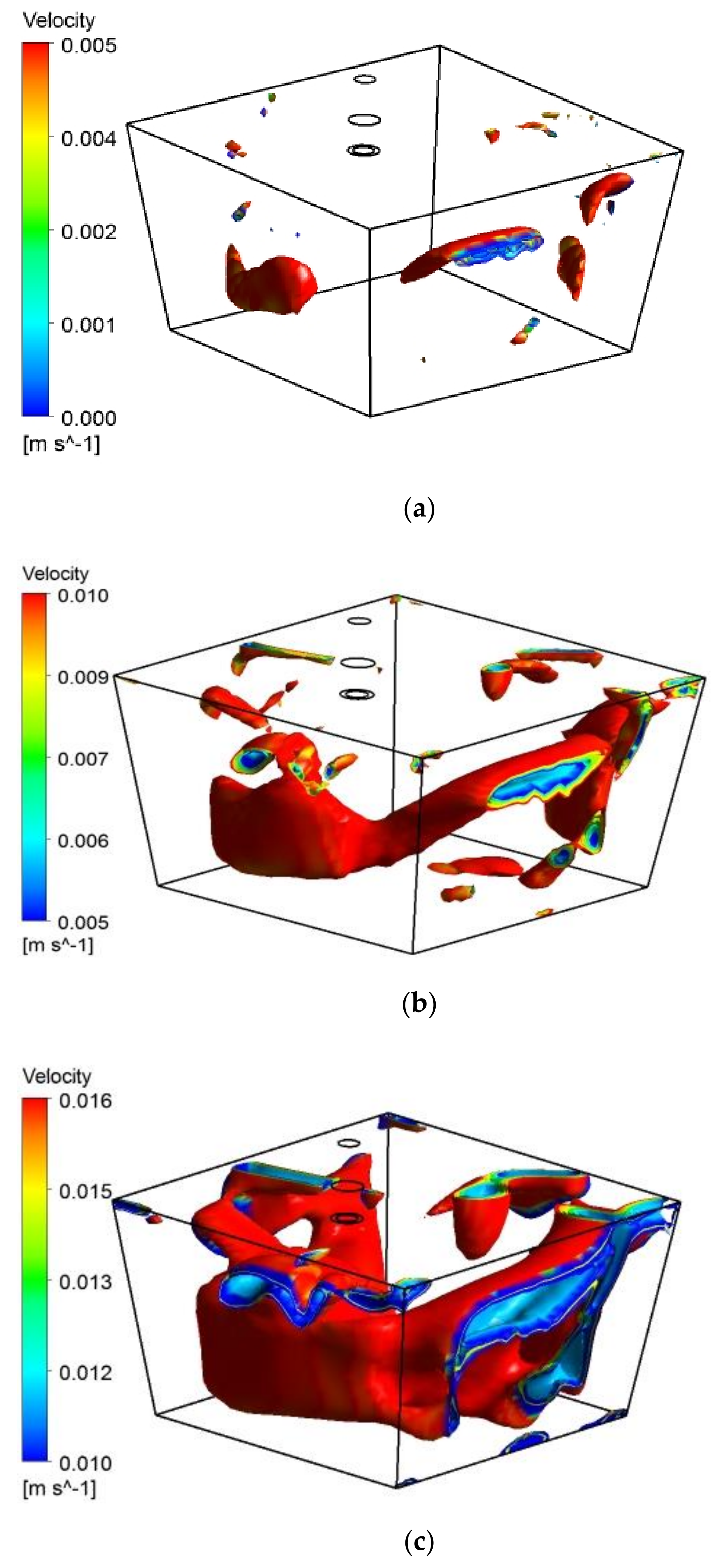
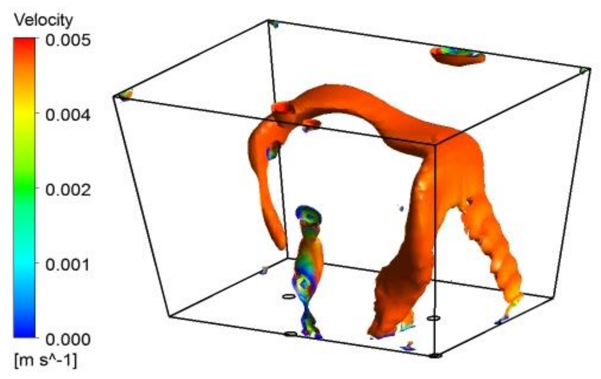
Table 10 shows the volume fraction of dead region in the receiving chamber under different critical velocities. A three-dimensional visualization region can be observed in the Figure 10. Figure 10a–c shows the iso-surface of flow velocity at 0.001 to 0.005 m/s, 0.005 to 0.010 m/s and 0.010 to 0.016 m/s, respectively, in the receiving chamber. It can be seen that the areas where fluid flows slowly appears on the middle area close to the wall, above the channel and far away from the ladle shroud, therefore, it is more convenient and reliable to optimize performance of fluid flow by the three-dimensional visualization. Meanwhile, Table 11 shows the volume fraction of dead region in the discharging chamber under different critical velocities, and the iso-surface of flow velocity at 0.001 to 0.004736 m/s as shown in the Figure 11. The comparison of the iso-surface of the flow velocity in the receiving chamber and discharging chamber shows that the fluid flow has been fully developed, and the longer mean residence time in the discharging chamber results in a smaller dead volume.
The above analysis method is an effective method to study the flow characteristics in a metallurgical vessel with a special structure and optimize the structure to obtain good dynamic conditions.

5. Conclusions

This paper gives a detailed numerical investigation on flow characteristics of molten steel in the tundish with channel induction heating. The individual unit method and volume subtraction model are proposed to investigate flow characteristics, meanwhile, based on past studies, a quantitative evaluation method of flow characteristics in the tundish with channel induction heating is proposed to show the three-dimensional visualization of dead region, and the volume subtraction method is applied to explore the flow characteristics in the combined metallurgical vessel. The following conclusions were drawn from the research:
(1)
In the receiving chamber with and without induction heating, the main flow behavior of molten steel is mixed flow.
(2)
In the channel with and without induction heating, the main flow behavior of molten steel is plug flow, and the dead volume can be considered as zero due to the developed pipe flow and spiral flow.
(3)
In the discharging chamber with and without induction heating, the main flow pattern of molten steel is mixed flow, and the minor flow pattern is plug flow. The discharging chamber is dominated by these two flow patterns.
(4)
The method of comparing the RTD curve and the flow behavior of the flow field is used to evaluate the complex flow in the combined metallurgical reactor, which is a good research idea.
(5)
The certain critical velocity u d 1 and u d 2 are defined in the receiving chamber and discharging chamber respectively, and the dead area in the tundish can be observed clearly by mathematical derivation and CFD-POST statistics.

Author Contributions

Manuscript Writing: B.Y.; Theoretical Analysis: H.L.; Literature Retrieval: Y.X.; Theoretical Guidance and Analysis: K.L.; Article Review: P.H. All authors have read and agreed to the published version of the manuscript.

Funding

Fundamental Research Funds for University of Science and Technology LiaoNing(2020QN02).

Institutional Review Board Statement

Not applicable.

Informed Consent Statement

Not applicable.

Data Availability Statement

No new data were created or analyzed in this study. Data sharing is not applicable to this article.

Acknowledgments

This work are grateful to the Fundamental Research Funds for University of Science and Technology LiaoNing (2020QN02) for the financial support of current work.

Conflicts of Interest

The authors declare no conflict of interest.

References

  1. Mazumdar, D. Review, Analysis, and Modeling of Continuous Casting Tundish Systems. Steel Res. Int. 2018, 90, 1800279. [Google Scholar] [CrossRef]
  2. Mazumdar, D. Tundish Metallurgy: Towards Increased Productivity and Clean Steel. Trans. Indian Inst. Met. 2013, 66, 597–610. [Google Scholar] [CrossRef]
  3. Sahai, Y. Tundish Technology for Casting Clean Steel: A Review. Met. Mater. Trans. A 2016, 47, 2095–2106. [Google Scholar] [CrossRef]
  4. Wang, Q.; Liu, Y.; Huang, A.; Yan, W.; Gu, H.; Li, G. CFD Investigation of Effect of Multi-hole Ceramic Filter on Inclusion Removal in a Two-Strand Tundish. Met. Mater. Trans. A 2019, 51, 276–292. [Google Scholar] [CrossRef]
  5. Raghavendra, K.; Sarkar, S.; Ajmani, S.; Denys, M.; Singh, M. Mathematical modelling of single and multi-strand tundish for inclusion analysis. Appl. Math. Model. 2013, 37, 6284–6300. [Google Scholar] [CrossRef]
  6. Ling, H.; Zhang, L. Numerical Simulation of the Growth and Removal of Inclusions in the Molten Steel of a Two-Strand Tundish. JOM 2013, 65, 1155–1163. [Google Scholar] [CrossRef] [Green Version]
  7. Joo, S.; Guthrie, R.I.L. Inclusion behavior and heat-transfer phenomena in steelmaking tundish operations: Part I. Aqueous modeling. Met. Mater. Trans. A 1993, 24, 755–765. [Google Scholar] [CrossRef]
  8. Joo, S.; Han, J.W.; Guthrie, R.I.L. Inclusion behavior and heat-transfer phenomena in steelmaking tundish operations: Part II. Mathematical model for liquid steel in tundishes. Met. Mater. Trans. A 1993, 24, 767–777. [Google Scholar] [CrossRef]
  9. Zhang, L.; Taniguchi, S.; Cai, K. Fluid flow and inclusion removal in continuous casting tundish. Met. Mater. Trans. A 2000, 31, 253–266. [Google Scholar] [CrossRef]
  10. Miki, Y.; Thomas, B.G. Modeling of inclusion removal in a tundish. Metall. Mater. Trans. B 1999, 30, 639–654. [Google Scholar] [CrossRef]
  11. Chattopadhyay, K.; Isac, M.; Guthrie, R.I.L. Physical and Mathematical Modelling of Inert Gas Shrouding in a Tundish. ISIJ Int. 2011, 51, 573–580. [Google Scholar] [CrossRef] [Green Version]
  12. Chattopadhyay, K.; Isac, M.; Guthrie, R.I.L. Physical and Mathematical Modelling of Steelmaking Tundish Operations: A Review of the Last Decade (1999–2009). ISIJ Int. 2010, 50, 331–348. [Google Scholar] [CrossRef] [Green Version]
  13. Warzecha, M.; Merder, T.; Warzecha, P.; Stradomski, G. Experimental and Numerical Investigations on Non-metallic Inclusions Distribution in Billets Casted at a Multi-strand Continuous Casting Tundish. ISIJ Int. 2013, 53, 1983–1992. [Google Scholar] [CrossRef] [Green Version]
  14. Warzecha, M.; Merder, T.; Pfeifer, H.; Pieprzyca, J. Investigation of Flow Characteristics in a Six-Strand CC Tundish Combining Plant Measurements, Physical and Mathematical Modeling. Steel Res. Int. 2010, 81, 987–993. [Google Scholar] [CrossRef]
  15. Mazumdar, D.; Guthrie, R.I.L. The Physical and Mathematical Modelling of Continuous Casting Tundish System. ISIJ Int. 1999, 39, 524–547. [Google Scholar] [CrossRef]
  16. Pardeshi, R.; Basak, S.; Singh, A.K.; Basu, B.; Mahashabde, V.; Roy, S.K.; Kumar, S. Mathematical Modeling of the Tundish of a Single-Strand Slab Caster. ISIJ Int. 2004, 44, 1534–1540. [Google Scholar] [CrossRef] [Green Version]
  17. Cwudziński, A. Numerical and Physical Modeling of Liquid Steel Active Flow in Tundish with Subflux Turbulence Controller and Dam. Steel Res. Int. 2013, 85, 902–917. [Google Scholar] [CrossRef]
  18. Cwudziński, A. Numerical, Physical, and Industrial Experiments of Liquid Steel Mixture in One Strand Slab Tundish with Flow Control Devices. Steel Res. Int. 2013, 85, 623–631. [Google Scholar] [CrossRef]
  19. Cwudziński, A. Numerical, Physical, and Industrial Studies of Liquid Steel Chemical Homogenization in One Strand Tundish with Subflux Turbulence Controller. Steel Res. Int. 2014, 86, 972–983. [Google Scholar] [CrossRef]
  20. Tripathi, A.; Ajmani, S.K. Effect of Shape and Flow Control Devices on the Fluid Flow Characteristics in Three Different Industrial Six Strand Billet Caster Tundish. ISIJ Int. 2011, 51, 1647–1656. [Google Scholar] [CrossRef] [Green Version]
  21. Tripathi, A.; Ajmani, S.K. Numerical Investigation of Fluid Flow Phenomenon in a Curved Shape Tundish of Billet Caster. ISIJ Int. 2005, 45, 1616–1625. [Google Scholar] [CrossRef] [Green Version]
  22. Chattopadhyay, K.; Isac, M.; Guthrie, R.I.L. Effect of flow modifiers on liquid metal cleanliness in four-strand delta shaped billet caster tundish. Ironmak. Steelmak. 2012, 39, 454–462. [Google Scholar] [CrossRef]
  23. Neves, L.; Tavares, R.P. Analysis of the mathematical model of the gas bubbling curtain injection on the bottom and the walls of a continuous casting tundish. Ironmak. Steelmak. 2016, 44, 559–567. [Google Scholar] [CrossRef]
  24. Lopez-Ramirez, S.; Palafox-Ramos, J.; Morales, R.D.; Barreto, J.D.J.; Zacharias, D. Modeling study of the influence of turbulence inhibitors on the molten steel flow, tracer dispersion, and inclusion trajectories in tundishes. Met. Mater. Trans. A 2001, 32, 615–627. [Google Scholar] [CrossRef]
  25. Chakraborty, S.; Sahai, Y. Effect of holding time and surface cover in ladles on liquid steel flow in continuous casting tundishes. Met. Mater. Trans. A 1992, 23, 153–167. [Google Scholar] [CrossRef]
  26. Palafox-Ramos, J.; Barreto, J.D.J.; Lopez-Ramirez, S.; Morales, R. Melt flow optimisation using turbulence inhibitors in large volume tundishes. Ironmak. Steelmak. 2001, 28, 101–109. [Google Scholar] [CrossRef]
  27. Ni, P.; Jonsson, L.T.I.; Ersson, M.; Jönsson, P.G. Non-Metallic Inclusion Behaviors in a New Tundish and SEN Design Using a Swirling Flow during Continuous Casting of Steel. Steel Res. Int. 2016, 88, 1600155. [Google Scholar] [CrossRef]
  28. Tkadlečková, M.; Walek, J.; Michalek, K.; Huczala, T. Numerical Analysis of RTD Curves and Inclusions Removal in a Multi-Strand Asymmetric Tundish with Different Configuration of Impact Pad. Metals 2020, 10, 849. [Google Scholar] [CrossRef]
  29. Wang, Q.; Qi, F.; Li, B.; Tsukihashi, F. Behavior of Non-metallic Inclusions in a Continuous Casting Tundish with Channel Type Induction Heating. ISIJ Int. 2014, 54, 2796–2805. [Google Scholar] [CrossRef] [Green Version]
  30. Yue, Q.; Zhang, C.B.; Pei, X.H. Magnetohydrodynamic flows and heat transfer in a twin-channel induction heating tundish. Ironmak. Steelmak. 2016, 44, 227–236. [Google Scholar] [CrossRef]
  31. Xing, F.; Zheng, S.; Zhu, M. Motion and Removal of Inclusions in New Induction Heating Tundish. Steel Res. Int. 2018, 89, 1700542. [Google Scholar] [CrossRef]
  32. Lei, H.; Yang, B.; Bi, Q.; Xiao, Y.; Chen, S.; Ding, C. Numerical Simulation of Collision-Coalescence and Removal of Inclusion in Tundish with Channel Type Induction Heating. ISIJ Int. 2019, 59, 1811–1819. [Google Scholar] [CrossRef] [Green Version]
  33. Xing, F.; Zheng, S.; Liu, Z.; Zhu, M. Flow Field, Temperature Field, and Inclusion Removal in a New Induction Heating Tundish with Bent Channels. Metals 2019, 9, 561. [Google Scholar] [CrossRef] [Green Version]
  34. Yang, B.; Lei, H.; Bi, Q.; Jiang, J.; Zhang, H.; Zhao, Y.; Zhou, J.-A. Electromagnetic Conditions in a Tundish with Channel Type Induction Heating. Steel Res. Int. 2018, 89, 1800145. [Google Scholar] [CrossRef]
  35. Yang, B.; Lei, H.; Bi, Q.; Jiang, J.; Zhang, H.; Zhao, Y.; Zhou, J.-A. Fluid Flow and Heat Transfer in a Tundish with Channel Type Induction Heating. Steel Res. Int. 2018, 89, 1800173. [Google Scholar] [CrossRef]
  36. Tang, H.; Guo, L.; Wu, G.; Xiao, H.; Yao, H.; Zhang, J. Hydrodynamic Modeling and Mathematical Simulation on Flow Field and Inclusion Removal in a Seven-Strand Continuous Casting Tundish with Channel Type Induction Heating. Metals 2018, 8, 374. [Google Scholar] [CrossRef] [Green Version]
  37. Yue, Q.; Pei, X.; Zhang, C.; Wang, X. Magnetohydrodynamics Calculation on Double-loop Channel Induction Tundish. Arch. Metall. Mater. 2018, 63, 329–336. [Google Scholar] [CrossRef]
  38. Sahai, Y.; Emi, T. Melt Flow Characterization in Continuous Casting Tundishes. ISIJ Int. 1996, 36, 667–672. [Google Scholar] [CrossRef]
  39. Sahai, Y.; Ahuja, R. Steel Flow and Mixing of Melt in Steelmaking Tundishes. Ironmak. Steelmak. 1986, 13, 241–247. [Google Scholar]
  40. Lei, H. New Insight into Combined Model and Revised Model for RTD Curves in a Multi-strand Tundish. Met. Mater. Trans. A 2015, 46, 2408–2413. [Google Scholar] [CrossRef]
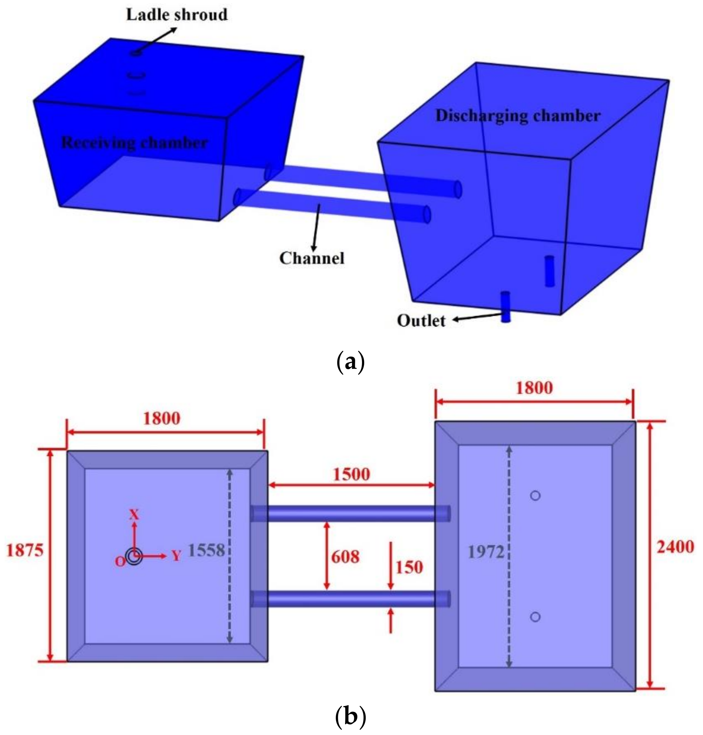
Figure 1. Tundish with channel induction heating (all dimensions are in mm). (a) Tundish model; (b) top view; (c) front view; (d) mesh of tundish.
Metals 11 01937 g001aMetals 11 01937 g001b
Figure 2. RTD curve in the tundish for water model and numerical simulation.
Metals 11 01937 g002
Figure 3. The schematic structural diagram of measurement method of RTD.
Metals 11 01937 g003
Figure 4. RTD curves for the tundish with and without channel induction heating. (a) RTD curve in the receiving chamber; (b) RTD curve in the channel; (c) RTD curve in the discharging chamber.
Metals 11 01937 g004aMetals 11 01937 g004b
Figure 5. Velocity vector in the tundish with and without channel induction heating. (a) Without induction heating, × = −0.379 (YZ plane); (b) With induction heating, × = −0.379 (YZ plane).
Metals 11 01937 g005
Figure 6. Schematic diagram of unit subtraction tracer measurement method.
Metals 11 01937 g006
Figure 7. RTD curves in the tundish. (a) Without channel induction heating; (b) With channel induction heating.
Metals 11 01937 g007
Figure 8. Flow pattern in the tundish without channel induction heating. (a) Streamline at vertical plane, × = −0.379 (YZ plane); (b) velocity vector in the inlet of channel Y = 0.775 (XZ plane); (c) velocity vector in the middle of channel Y = 1.635 (XZ plane); (d) velocity vector in the outlet of channel Y = 2.51 (XZ plane); (e) velocity vector in the channel × = −0.379 (YZ plane).
Metals 11 01937 g008aMetals 11 01937 g008b
Figure 9. Flow pattern in the tundish with channel induction heating. (a) Streamline at vertical plane, X = −0.379 (YZ plane); (b) velocity vector in the inlet of channel, Y = 0.775 (XZ plane); (c) velocity vector in the middle of channel, Y = 1.635 (XZ plane); (d) velocity vector in the outlet of channel, Y = 2.51 (XZ plane); (e) streamline in the channel, X = −0.379 (YZ plane).
Metals 11 01937 g009aMetals 11 01937 g009b
Figure 10. Three-dimensional visualization of dead region in the receiving chamber. (a) The isosurface of flow velocity at 0.001 to 0.005 m/s; (b) the isosurface of flow velocity at 0.005 to 0.010 m/s; (c) the isosurface of flow velocity at 0.010 to 0.016 m/s.
Metals 11 01937 g010
Figure 11. Three-dimensional visualization of dead region in the discharging chamber.
Metals 11 01937 g011
Table 1. The operating parameters, geometry parameters and physical parameters of computational models.
ParametersValueUnits
Strands2-
Volumetric flow rate at the ladle shroud14 m 3 / h
Volume of receiving chamber2.826 m 3
Volume of channel0.062 m 3
Volume of discharging chamber5.243 m 3
Submergence depth of shroud150mm
Relative permeability of molten steel1-
Relative permeability of iron core1000-
Resistivity of molten steel1.4 × 10−6 Ω m
Relative permeability of copper coil1-
Relative permeability of air1-
Thermal conductivity of molten steel41 ( W / ( m K ) )
Heat capacity of molten steel750 ( J / ( k g K ) )
Density of molten steel(8523–0.8358T) ( k g / m 3 )
Relative permeability of molten steel1-
Relative permeability of iron core1000-
Table 2. Analysis approach for the residence time distribution (RTD) curve [38,39,40].
ParametersCombined Model
Mean residence time t ¯ = 0 c t d t 0 c d t
Dimensionless time τ = t ¯ t 0
Theoretical residence time t 0 = v q
Dead volume fraction V d = 1 τ
Plug volume fraction V p = t min 2 t 0 + t max 2 t 0
Well-mixed volume fraction V m = 1 V d V p
Table 3. Heat losses of wall, velocity and temperature of inlet from the tundish.
ParameterValueUnits
Heat loss of free surface8000W/m2
Heat loss of bottom1800W/m2
Heat loss of wide wall4000W/m2
Heat loss of narrow wall4200W/m2
Heat loss of channel wall1100W/m2
Velocity of ladle shroud0.5m/s
Temperature of ladle shroud1800K
Table 4. Analysis result of velocity for different grid numbers.
Grid Numbers196,156248,300300,318324,848350,580
Test pointMMMMM
Velocity ( m / s )0.1252710.1263330.1266740.12583240.125795
Table 5. Fluid flow characteristics in the tundish for water model and numerical simulation.
Cases V P V d V m
Numerical calculate33.05%9.55%57.40%
Water model33.72%9.48%56.80%
Table 6. Simulation performed for the individual unit method.
Metallurgical ContainersAddition PositionMonitor PositionTracer
Receiving chamberAB1
ChannelBC2
Discharging chamberCD3
Table 7. Analysis results for the RTD curve with the combined model in the tundish with and without channel induction heating.
CasesResidence Time (s)Volume (m3)
t A B , a v t B C , a v t C D , a v V A B , P V V B C , P V V C D , P V V A B , M V V B C , M V V C D , M V V A B , D V V B C , D V V C D , D V
1544.416.2907.40.0630.0510.3452.0750.0133.2180.688−0.0031.70
2547.217.5996.80.1450.0510.0352.0040.0173.8790.677−0.0071.33
Note: 1 is the tundish without channel induction heating, 2 is the tundish with channel induction heating.
Table 8. Simulation performed for the volume subtraction model.
Addition PointMonitor PointVolumeNotes
AB V A B -
AC V A C V A C V A B = V B C O
AD V A D V A D V A C = V C D O
Table 9. Analysis results for the RTD curve with the combined model in the tundish with and without channel induction heating.
CasesResidence Time (s)Volume (m3)
t A B , av t A C , av t A D , av t B C O , av t C D O , av V A B , P V V A C , P V V A D , P V V B C O , P V V C D , P V
Without induction heating544.4563.71850.119.31286.40.06280.12172.240.05892.118
With induction heating547.2623.51812.176.31188.60.14610.20702.030.06091.822
Cases V A B , M V V A C , M V V A D , M V V B C O , M V V C D O , M V V A B , D V V A C , D V V A D , D V V B C O , D V V C D O , M V
Without induction heating2.0752.0925.0250.0172.9330.6880.6700.866−0.0180.1957
With induction heating2.0042.2405.0800.2362.8400.6770.4361.015−0.2410.5791
Table 10. Volume fraction of dead region in the receiving chamber under different critical velocities.
u d 1   ( m / s ) V d 1   ( m 3 ) V d 1 / V A B   ( % )
0.0010.0003120.011
0.0020.0028600.101
0.0030.0081700.289
0.0040.0163000.577
0.0050.0293001.037
0.0060.04621.635
0.0070.06952.460
0.0080.10203.609
0.0090.14104.990
0.0100.19006.723
0.0110.24408.634
0.0120.314011.11
0.0130.393013.907
0.0140.486017.197
0.0150.580020.523
0.0160.688024.345
Note: u d 1 is a certain critical velocity in the receiving chamber, V d 1 represents the dead region volume in the receiving chamber, V A B is the volume of receiving chamber.
Table 11. Volume fraction of dead region in the discharging chamber under different critical velocities.
u d 2   ( m / s ) V d 2   ( m 3 ) V d 2 / V C D   ( % )
0.0010.001620.0309
0.0020.01110.212
0.0030.0430.820
0.0040.1011.926
0.0047360.1783.395
Note: u d 2 is a certain critical velocity in the discharging chamber, V d 2 represents the dead region volume in the discharging chamber, V C D is the volume of discharging chamber.
Publisher’s Note: MDPI stays neutral with regard to jurisdictional claims in published maps and institutional affiliations.