1. Introduction
Shape memory alloys (SMAs) are often used as actuators [
1,
2,
3] in automotive, aerospace and biomedical fields [
4,
5,
6,
7] because of their ability to convert thermal energy into mechanical energy. This effect is the result of the reversible and diffusionless solid–solid phase transformation between the martensitic low-temperature phase and the austenitic high-temperature phase. As soon as the austenite start temperature
is exceeded, the high-temperature phase begins to form until the austenite finish temperature
is reached. Because of the thermal hysteresis, the martensite start temperature
and the finish temperature
are not the same as the transition temperatures of the high-temperature phase.
If martensitic SMAs are plastically deformed and afterward heated up above
, all deformations are removed, and the alloy “remembers” its initial shape. In addition, SMAs can be trained to remember their shape in the low-temperature phase, too. In this case, they switch between both forms by heating and cooling. Furthermore, the alloys show a pseudoelastic behavior in the austenitic high-temperature phase because of the phase transformation to stress-induced martensite. This means that the strain goes up to 10% [
8] while the specimen is stressed. After unloading, the extension decreases at lower stress values due to mechanical hysteresis.
NiTi is the most important SMA for commercial applications. Aside from the pronounced shape memory effect, the material is biocompatible and has excellent resistance to corrosion [
9]. The addition of copper to the binary system reduces the quantity of nickel [
9] and influences the properties. One result of the additional element is shown in a decrease of the thermal hysteresis. Furthermore, the mechanical hysteresis during the pseudoelasticity diminishes too, and the thermo-mechanical cycling stability grows [
10]. Moreover, if the quantity of copper exceeds 10 at.%, then the material begins to embrittle [
9].
To join SMAs with similar and dissimilar materials, fusion welding processes, such as tungsten inert gas welding [
11,
12] or electron beam welding [
13,
14], are often applied. Laser beam welding is used especially frequently because of the high welding speed and the minimal heat input. However, all fusion welding processes show some problems. For example, brittle intermetallic compounds emerge, the joint strength decreases, and the transformation temperatures change [
15]. Falvo et al. [
16] joined two similar NiTi sheets with an Nd:YAG laser. As a result of this process, the material embrittled, and the ultimate tensile strength was reduced by more than 50%, down to 520 MPa. However, Zeng et al. [
17] produced laser beam-welded composites of wires and tubes with similar and dissimilar NiTi alloys. The resulted joint break force for both combinations amounted to over 70% in comparison to the base material (BM). Additionally, the phase transformation temperatures were varied after the welding process. The
and
of the similar material joints increased from 19.25 to 91.7 °C and −12.7 to 29.1 °C, respectively.
In order to reduce the negative influences of the fusion welding, novel approaches, such as solid-state methods, such as friction stir welding [
18,
19] or adhesive bonding [
20,
21], should be used for joining. Another useful and promising solid-state process is ultrasonic spot welding (USW) because of the very short welding time, the low-heat input and the resulting minimal electrical contact resistance. Zhang et al. [
22] investigated the mechanical behavior of similar ultrasonic welded NiTi sheets. They noted that the process did not generate detrimental intermetallic compounds. Additionally, the highest tensile load was more than 50% in comparison to the BM. This was a result of the partially-bonded weld interface, which is typical for USW. However, minimally-varied phase transition temperatures were achieved. In another study from Zhang et al. [
23], similar results were achieved by using a copper interlayer between NiTi sheets. No intermetallic compounds were noticed after USW and the joint strength increased due to the interlayer up to 64% compared to the BM.
The intention of this study is to create strong ultrasonic welded joints of NiTiCu SMA wires and silver-coated ferrules. These joints should have a low electrical resistance to conduct electricity through the ferrules to the wires, causing them to heat up, change shape, and move as an actuator. Therefore, the optimal welding parameters were determined by a design of experiments (DoE). Furthermore, tensile tests accompanied by electrical resistance measuring were carried out, and the resulting joints were investigated by scanning electron microscopy (SEM), energy-dispersive X-ray spectroscopy (EDS) and differential scanning calorimetry (DSC).
2. Materials and Methods
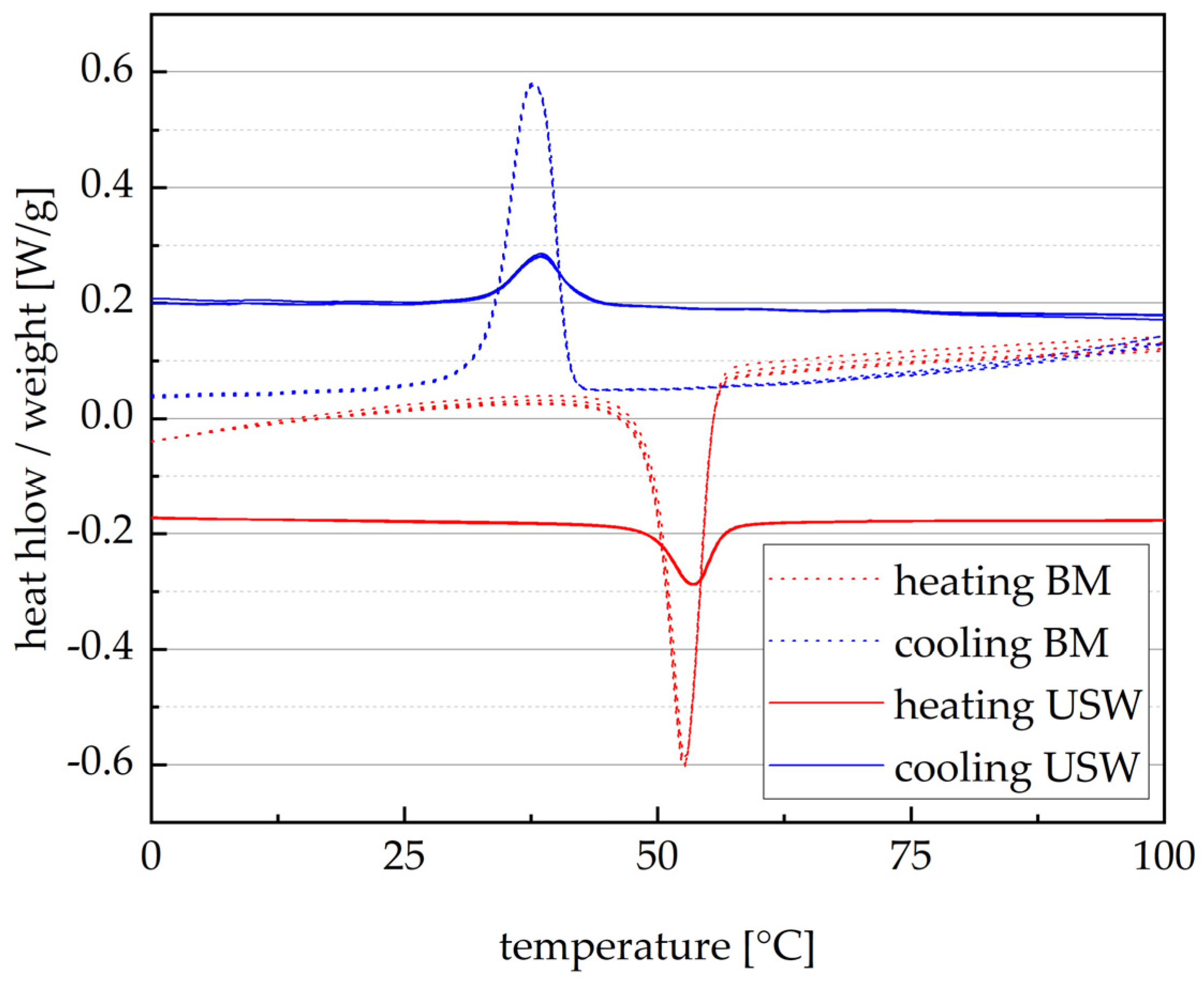
In this study, wires with a diameter of 200 µm consisting of a NiTiCu SMA were joined with a silver-coated copper ferrule by ultrasonic spot welding. Preliminary EDS has shown that the wire is composed of 49 at.% titanium, 43 at.% nickel, 8 at.% copper and less than 0.01 at.% of other elements. Furthermore, DSC of the SMA was carried out before and after USW by a cooling and heating rate of 10 K/min in a nitrogen atmosphere. The results revealed that the transition temperatures of the BM are and . That means that the wire is in the state of the low-temperature phase at room temperature. Furthermore, the specimens were heated and cooled for five repetitions to evaluate stabilizing effects.
The second joining partner was a silver-coated copper ferrule with a length
l of 5 mm, an inner diameter
d1 of 1 mm, an outer diameter
d2 of 1.8 mm and a wall thickness
s of 0.2 mm. Its dimensions are shown in
Figure 1.
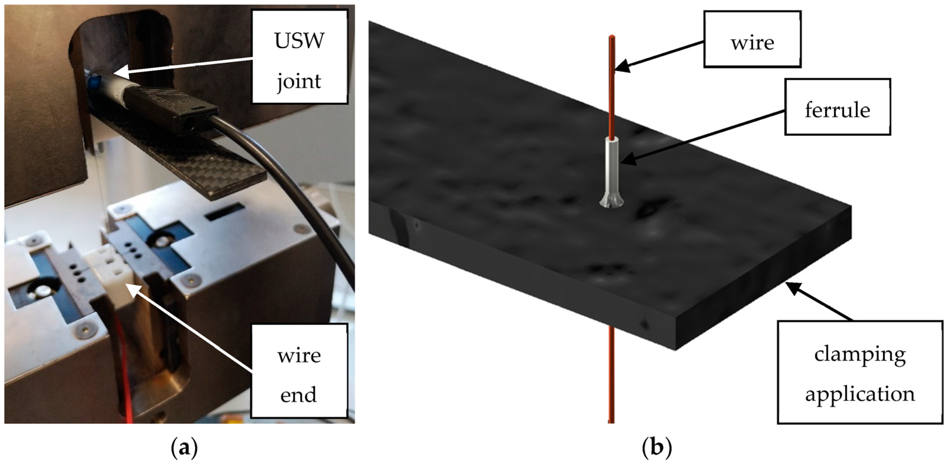
The wires were welded to the ferrules by a linear USW machine MPX-50-2 (Telsonic GmbH, Bronschhofen, Switzerland). This device had a maximum generator power of 6.5 kW and could weld wires with diameters between 20 µm and 2 mm. The SMA wires were threaded through the ferrules and placed under the horn. In order to fix the wires, the wire ends have been clamped firmly. A total of six joints have been developed, three each for examination with and without subsequent heat treatment.
The determination of optimum welding parameters for joining the NiTiCu wires and the silver-coated ferrules took place by using a DoE and an analysis of means (ANOM). For this purpose, three levels were selected for each welding parameter (
Table 1), and a total of nine parameter sets with different parameter levels were created. Each parameter set was welded three times. The results of the following tensile tests on these samples (
Table 2) formed the basis of the ANOM. This analysis calculated the optimal welding parameters, which were used subsequently to investigate the joints. They are shown in
Table 3.
After welding, the specimens were mechanically and microstructurally investigated. Therefore, the tensile testing machine ProLine (ZwickRoell GmbH & Co. KG, Ulm, Germany) was used to study the mechanical behavior of the wires by a cycle speed of 0.1%/s. The resulted stress was calculated by dividing the measured force by the cross-sectional area of the wire. For determining the elongation, the distance between the fixed joint and the clamped wire end was examined. To clamp the specimen, the wires of the BM were crimped with a ferrule on each end and then fixed in luster terminals, which were fastened in the restraints of the tensile testing machine. This allows both luster terminals to be connected to a resistance meter. Regular clamping of the tensile testing machine is not expedient for evaluating the tensile strength of this joint type. Therefore, a clamping application was built out of a carbon-fiber-reinforced plastic cuboid, which had a 0.3 mm drilled hole at the front. Thus, the wire was led through the hole while the movement of the welded ferrule was prevented by the cuboid (
Figure 2b). In addition, the application is clamped at the top of the tensile testing machine, and the wire end is fixed in a luster terminal at the bottom. This luster terminal and the welded ferrule were connected with a resistance meter to measure the electrical resistance while tensile testing.
For the microstructural investigations, the scanning electron microscope ZEISS LEO1455VP (Carl Zeiss AG, Oberkochen, Germany) was used, and all recordings were taken at an acceleration voltage of 25 keV. Furthermore, the EDS of the BM and the welded joint was carried out on the same microscope in order to analyze whether the USW process had influenced the composition of the phases.
4. Discussion
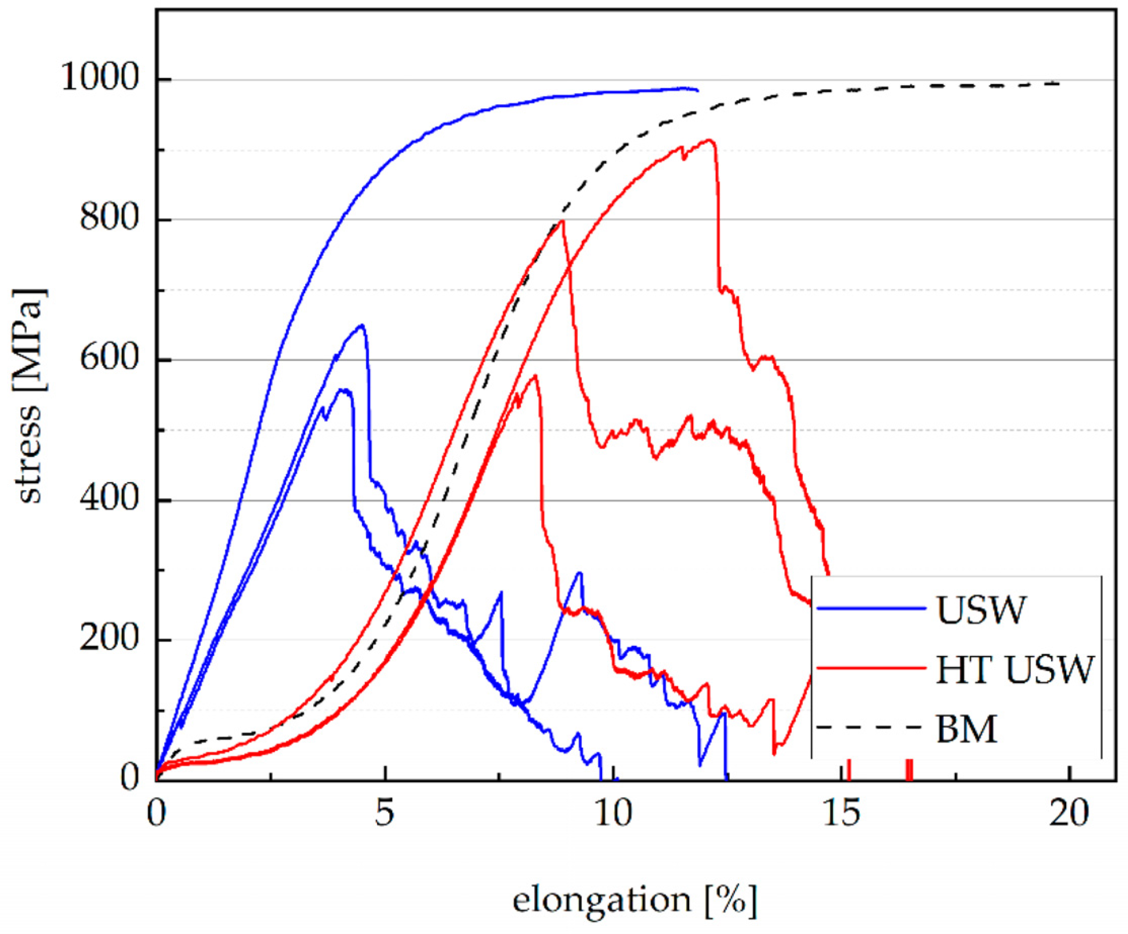
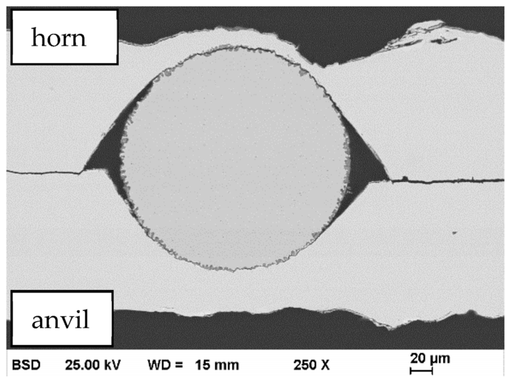
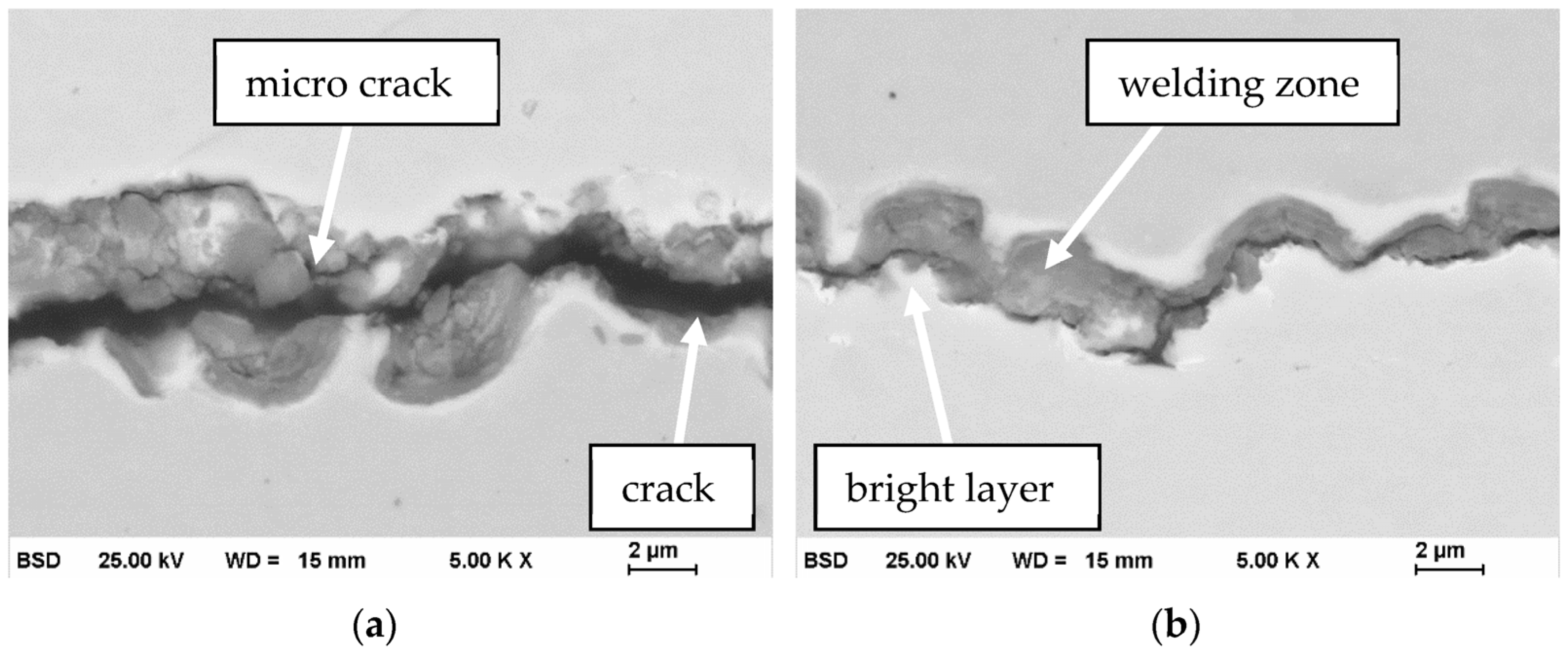
Only one specimen of the welded joints was broken in tensile testing, while all the other wires were pulled out of the ferrules. This broken specimen has an ultimate tensile strength of almost 100% compared to the BM, which means that the joint strength could be higher than the ultimate tensile strength of the wire. The reason why only one joint has this high degree of strength could be that the wires are often not connected to the ferrule to the maximum extend, which is also seen in the SEM pictures because of cracks and microcracks in the welding zones. This can be a consequence of the fact that the welding energy is too high, causing the destruction of micro-connections in the welding zone after joining, which is especially the case on the horn side since the energy on the anvil side is dampened by softening effects. However, the non-broken joints achieved tensile strengths between 56% and 92%, which underlines the high potential of the solid-state welding process. Furthermore, the joints do not have a martensitic plateau after welding, which implies the martensite is completely detwinned. However, after a heat treatment over Af, the SMA behavior is completely rebuilt without any delay of elongation or stress. This means that the USW process deforms the SMA wires only by detwinning martensite and without creating dislocations.
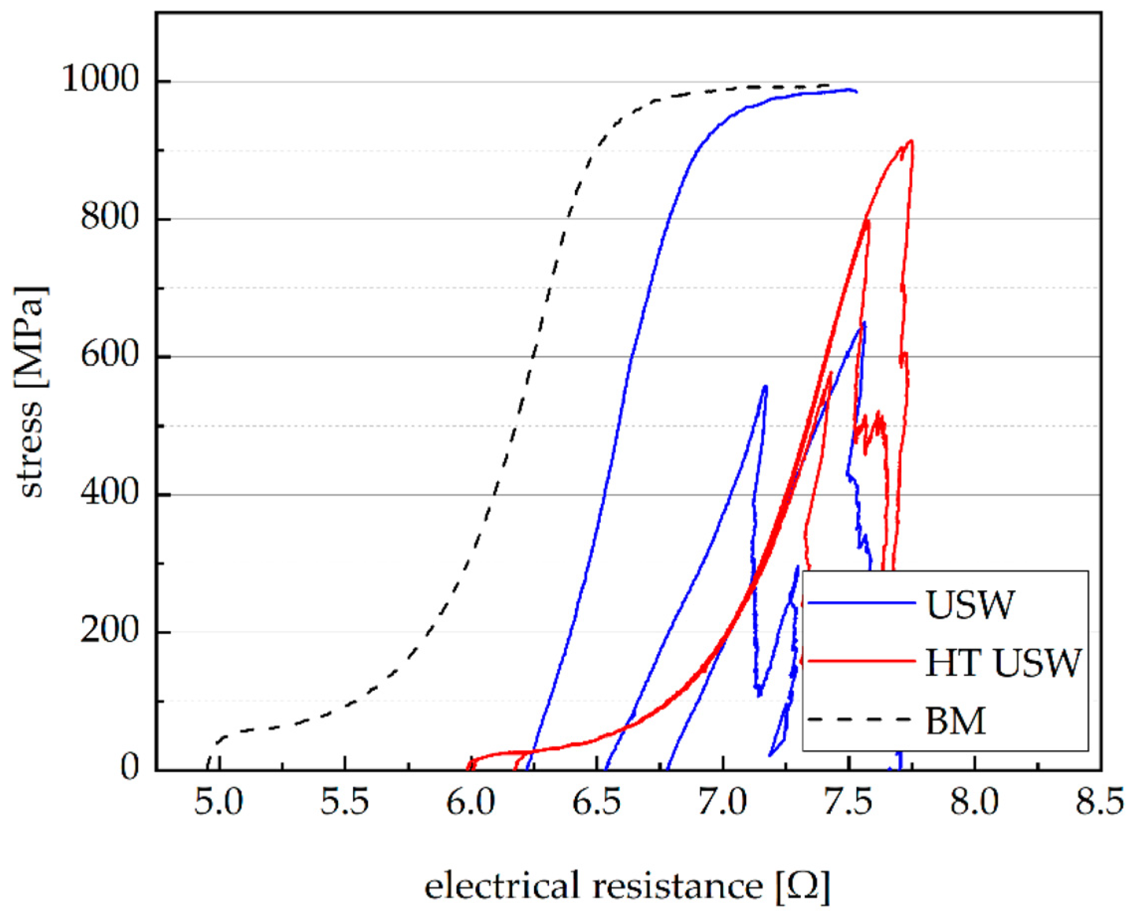
The rebuilt SMA behavior after heat treatment is also observed in the change of the electrical resistance during tensile tests. The delay of 1 Ω versus the BM could be due to the cracks and microcracks in the welding zone, which increase the total electrical resistance. Additionally, the newly generated compound of the welding zone could also influence the electrical resistance. Moreover, the similar behavior of stress/elongation and stress/electrical resistance is the consequence of the changed microstructure under load. Based on an expansion of stress, the martensite detwins, and the number of dislocations grows. In relation to Matthiessen’s rule, which means that the resistivity of the metal rises with the increasing number of lattice defects, the stress/elongation and stress/electrical resistance must behave similarly.
The EDS revealed that the proportion of copper in the welding zone of the anvil side is 13 at.% and, therefore, is higher than the NiTiCu BM (8 at.%). For a quantity of almost 50 at.% titanium, this indicates that the transition of the BM from the cubic B2 austenite to the monoclinic B19′ martensite must change. Therefore, if the temperature falls below
Mf, the B2 austenite will transform into orthorhombic B19 martensite as long as the ambient temperature is more than 250 K [
26]. In comparison, the welding zone of the horn side has a similar copper content, but that of titanium is only 39 at.%. This could mean that the welding zone of the horn side has a different phase composition than that of the anvil side. However, the welding temperatures of both sides should be similar, and the compositions of the joining partners are the same. In addition, the atomic radii of nickel and copper are comparable [
28], making the substitution of nickel by copper more plausible than of titanium. These reasons show that the welding zone of the anvil side must be similar to the horn side. The difference in the composition is due to the fact that the welding zone at the horn is not a homogeneous phase. Rather, the zone is divided into lots of micro-pieces of the NiTiCu wire and the copper ferrule, which is also seen in the SEM picture (
Figure 7a).
A lower endothermic and exothermic heat was found with DSC compared to the BM. This is a consequence of the decrease in the quantity of the SMA BM and of the isolation of the wire through the ferrule so that only a small signal is detectable. However, the transition temperatures could be determined reliably. Contrary to fusion welding processes, the DSC revealed that the USW exhibited only minor influences on the transition temperatures of the SMAs. It should also be helpful that the second joining partner is copper, for the reason that the higher composition of copper in the welding zone does not affect the transition temperatures, while orthorhombic B19 martensite is formed instead of monoclinic B19′ martensite [
26]. In addition, the SEM images did show that the welding zones are not wider than 10 µm, which means that the welding zones only have a minimal effect on the transition temperatures.
Author Contributions
Conceptualization, T.S., A.G., G.W., T.M. and W.-G.D.; methodology, T.S., A.G. and T.M.; formal analysis, T.S., A.G. and G.W.; investigation, T.S., A.G., G.W., T.M., B.S. and W.-G.D.; resources, G.W. and W.-G.D.; writing—original draft preparation, T.S.; writing—review and editing, T.S., A.G., G.W., T.M., B.S. and W.-G.D.; visualization, T.S. and A.G.; supervision, T.S., A.G., G.W., T.M. and W.-G.D.; project administration, A.G., G.W., T.M. and W.-G.D.; funding acquisition, A.G., G.W., T.M. and W.-G.D. All authors have read and agreed to the published version of the manuscript.
Funding
The publication of this article was funded by the Chemnitz University of Technology.
Data Availability Statement
Not applicable.
Acknowledgments
We thankfully acknowledge Mario Scholze for carrying out the DSC measurements and Husam Ahmad for investigating the joints by SEM and EDS.
Conflicts of Interest
The authors declare no conflict of interest.
References
- Ikuta, K. Micro/miniature shape memory alloy actuator. In Proceedings of the IEEE International Conference on Robotics and Automation, Cincinnati, OH, USA, 13–18 May 1990; pp. 2156–2161, ISBN 0-8186-9061-5. [Google Scholar]
- Gorbet, R.B.; Russell, R.A. A novel differential shape memory alloy actuator for position control. Robotica 1995, 13, 423–430. [Google Scholar] [CrossRef] [Green Version]
- Huang, X.; Kumar, K.; Jawed, M.K.; Mohammadi Nasab, A.; Ye, Z.; Shan, W.; Majidi, C. Highly Dynamic Shape Memory Alloy Actuator for Fast Moving Soft Robots. Adv. Mater. Technol. 2019, 4, 1800540. [Google Scholar] [CrossRef]
- Hannula, S.P.; Söderberg, O.; Jämsä, T.; Lindroos, V.K. Shape Memory Alloys for Biomedical Applications. Mater. Clin. Appl. VII 2006, 49, 109–118. [Google Scholar] [CrossRef]
- Yoneyama, T.; Miyazaki, S. Shape Memory Alloys for Biomedical Applications; Elsevier: Amsterdam, The Netherlands, 2008; ISBN 9781845695248. [Google Scholar]
- Costanza, G.; Tata, M.E. Shape Memory Alloys for Aerospace, Recent Developments, and New Applications: A Short Review. Matererials 2020, 13, 1856. [Google Scholar] [CrossRef] [Green Version]
- Jani, J.M.; Leary, M.; Subic, A. Shape Memory Alloys in Automotive Applications. Automot. Eng. Mobil. Res. 2014, 663, 248–253. [Google Scholar] [CrossRef]
- Ma, J.; Karaman, I.; Noebe, R.D. High temperature shape memory alloys. Int. Mater. Rev. 2010, 55, 257–315. [Google Scholar] [CrossRef]
- Lagoudas, D.C. Shape Memory Alloys: Modeling and Engineering Applications; Springer: Boston, MA, USA, 2008; ISBN 978-0-387-47684-1. [Google Scholar]
- Funakubo, H. (Ed.) Shape Memory Alloys; CRC Press: Boca Raton, FL, USA, 1984; ISBN 2881241360. [Google Scholar]
- Oliveira, J.P.; Barbosa, D.; Fernandes, F.M.B.; Miranda, R.M. Tungsten inert gas (TIG) welding of Ni-rich NiTi plates: Functional behavior. Smart Mater. Struct. 2016, 25, 03LT01. [Google Scholar] [CrossRef]
- Ikai, A.; Kimura, K.; Tobushi, H. TIG Welding and Shape Memory Effect of TiNi Shape Memory Alloy. J. Intell. Mater. Syst. Struct. 1996, 7, 646–655. [Google Scholar] [CrossRef]
- Yang, D.; Jiang, H.C.; Zhao, M.J.; Rong, L.J. Microstructure and mechanical behaviors of electron beam welded NiTi shape memory alloys. Mater. Des. 2014, 57, 21–25. [Google Scholar] [CrossRef]
- Krooß, P.; Günther, J.; Halbauer, L.; Vollmer, M.; Buchwalder, A.; Zenker, R.; Biermann, H.; Niendorf, T. Electron beam welding of Fe–Mn–Al–Ni shape memory alloy: Microstructure evolution and shape memory response. Funct. Mater. Lett. 2017, 10, 1750043. [Google Scholar] [CrossRef]
- Oliveira, J.P.; Miranda, R.M.; Braz Fernandes, F.M. Welding and Joining of NiTi Shape Memory Alloys: A Review. Prog. Mater. Sci. 2017, 88, 412–466. [Google Scholar] [CrossRef]
- Falvo, A.; Furgiuele, F.M.; Maletta, C. Laser welding of a NiTi alloy: Mechanical and shape memory behaviour. Mater. Sci. Eng. A 2005, 412, 235–240. [Google Scholar] [CrossRef]
- Zeng, Z.; Yang, M.; Oliveira, J.P.; Song, D.; Peng, B. Laser welding of NiTi shape memory alloy wires and tubes for multi-functional design applications. Smart Mater. Struct. 2016, 25, 85001. [Google Scholar] [CrossRef]
- Prabu, S.M.; Madhu, H.C.; Perugu, C.S.; Akash, K.; Mithun, R.; Kumar, P.A.; Kailas, S.V.; Anbarasu, M.; Palani, I.A. Shape memory effect, temperature distribution and mechanical properties of friction stir welded nitinol. J. Alloys Compd. 2019, 776, 334–345. [Google Scholar] [CrossRef] [Green Version]
- Lima, J.S.; Neto, A.C.W.; De Melo, R.H.F. Friction Stir Welding of Austenitic NiTi Shape Memory Alloys. Glob. J. Res. Eng. 2017, 17. Available online: https://engineeringresearch.org/index.php/GJRE/article/view/1596 (accessed on 1 October 2021).
- Man, H.C.; Zhao, N.Q. Enhancing the adhesive bonding strength of NiTi shape memory alloys by laser gas nitriding and selective etching. Appl. Surf. Sci. 2006, 253, 1595–1600. [Google Scholar] [CrossRef]
- Niccoli, F.; Alfano, M.; Bruno, L.; Furgiuele, F.; Maletta, C. Mechanical and Functional Properties of Nickel Titanium Adhesively Bonded Joints. J. Mater. Eng. Perform. 2014, 23, 2385–2390. [Google Scholar] [CrossRef]
- Zhang, W.; Ao, S.S.; Oliveira, J.P.; Zeng, Z.; Luo, Z.; Hao, Z.Z. Effect of ultrasonic spot welding on the mechanical behaviour of NiTi shape memory alloys. Smart Mater. Struct. 2018, 27, 85020. [Google Scholar] [CrossRef]
- Zhang, W.; Ao, S.; Oliveira, J.P.; Zeng, Z.; Huang, Y.; Luo, Z. Microstructural Characterization and Mechanical Behavior of NiTi Shape Memory Alloys Ultrasonic Joints Using Cu Interlayer. Materials 2018, 11, 1830. [Google Scholar] [CrossRef] [PubMed] [Green Version]
- Santosh, S.; Sampath, V. Experimental investigations on the effect of copper on the microstructure and shape memory characteristics of NiTi alloys. IOP Conf. Ser. Mater. Sci. Eng. 2020, 912, 52009. [Google Scholar] [CrossRef]
- Uno, T. Enhancing bondability with coated copper bonding wire. Microelectron. Reliab. 2011, 51, 88–96. [Google Scholar] [CrossRef]
- Tang, W.; Sandström, R.; Wei, Z.G.; Miyazaki, S. Experimental investigation and thermodynamic calculation of the Ti-Ni-Cu shape memory alloys. Met. Mater. Trans. A 2000, 31, 2423–2430. [Google Scholar] [CrossRef]
- Kanaya, K.; Okayama, S. Penetration and energy-loss theory of electrons in solid targets. J. Phys. D Appl. Phys. 1972, 5, 43–58. [Google Scholar] [CrossRef]
- Winter, M. The Periodic Table of the Elements by WebElements. Available online: https://www.webelements.com/ (accessed on 14 September 2021).
| Publisher’s Note: MDPI stays neutral with regard to jurisdictional claims in published maps and institutional affiliations. |
© 2021 by the authors. Licensee MDPI, Basel, Switzerland. This article is an open access article distributed under the terms and conditions of the Creative Commons Attribution (CC BY) license (https://creativecommons.org/licenses/by/4.0/).

 ,
, 


