Article

Performance Assessment and Chip Morphology Evaluation of Austenitic Stainless Steel under Sustainable Machining Conditions

by
Anshuman Das
1,
Smita Padhan
2,
Sudhansu Ranjan Das
2,
Mohammad S. Alsoufi
3,
Ahmed Mohamed Mahmoud Ibrahim
4 and
Ammar Elsheikh
5,*
1
Department of Mechanical Engineering, DIT University, Dehradun 248001, India
2
Department of Production Engineering, Veer Surendra Sai University of Technology, Burla 768018, India
3
Mechanical Engineering Department, College of Engineering and Islamic Architecture, Umm Al-Qura University, Makkah 24382, Saudi Arabia
4
Production Engineering and Mechanical Design Department, Faculty of Engineering, Minia University, Minya 61519, Egypt
5
Department of Production Engineering and Mechanical Design, Faculty of Engineering, Tanta University, Tanta 31527, Egypt
*
Author to whom correspondence should be addressed.
Metals 2021, 11(12), 1931; https://doi.org/10.3390/met11121931
Submission received: 28 October 2021 / Revised: 23 November 2021 / Accepted: 24 November 2021 / Published: 29 November 2021

Abstract

:
Sustainable manufacturing has received great attention in the last few decades for obtaining high quality products with minimal costs and minimal negative impacts on environment. Sustainable machining is one of the main sustainable manufacturing branches, which is concerned with improving environmental conditions, reducing power consumption, and minimizing machining costs. In the current study, the performance of three sustainable machining techniques, namely dry, compressed air cooling, and minimum quantity lubrication, is compared with conventional flood machining during the turning of austenitic stainless steel (Nitronic 60). This alloy is widely used in aerospace engine components, medical applications, gas power industries, and nuclear power systems due to its superior mechanical and thermal properties. Machining was performed using SiAlON ceramic tool with four different cutting speeds, feeds and a constant depth of cut. Consequently, various chip characteristics such as chip morphology, chip thickness, saw tooth distance and chip segmentation frequency were analyzed with both optical and scanning electron microscopes. Performance assessment was performed under the investigated cutting conditions. Our results show that the tool life under MQL machining are 138%, 72%, and 11% greater than dry, compressed air, and flooded conditions, respectively. The use of SiAlON ceramic tool results is more economically viable under the MQL environment as the overall machining cost per component is lower ($0.27) as compared to dry ($0.36), compressed air ($0.31), and flooded ($0.29) machining conditions. The minimum quantity lubrication technique outperformed the other investigated techniques in terms of eco-friendly aspects, economic feasibility, and technical viability to improve sustainability.

1. Introduction

Nitronic 60 is an austenitic stainless steel strengthened in the presence of nitrogen [1]. It has excellent strength and better resistance to wear and galling. It has outstanding corrosion and pitting resistant compared to 304 and 316 stainless steels. In every manufacturing industry, material cost is an important factor. Nitronic 60 stainless steel has the ability to provide more low-cost solutions to both wear and galling problems than bearing steel and high nickel alloys. That is why Nitronic 60 is popular in many industries. It has a wide range of applications in the automotive, bearing, chemical processing, and aerospace industries.
There are many advanced manufacturing processes which exist in order to obtain final products with neat shape in modern industries such as additive manufacturing, friction stir processing, and precision casting [2,3,4]. In machining, material is gradually removed from the specimen in the form of chips after elastic, plastic, and shear deformation with the application of a cutting tool [5,6,7]. There are three essential components for any kind of machining activities, namely a cutting tool, machine tool, and workpiece. The overall performance of any machining activity depends upon the workpiece-tool interaction [8]. Moreover, selection of machining variables highly depends upon the material properties of the tool and workpiece [9]. During machining of difficult to cut materials such as Nitronic 60, some major challenges generally occurred such as the generation of high heat and stress and increments in power consumption. As a result, these characteristics adversely affect various machining attributes. The situation will be uncontrollable if improper machining parameters will be selected. Moreover, getting a maintenance-free and hazardous-free environment during machining is not always possible.
During the machining process, particularly when difficult to cut materials or hard materials are involved, different types of chips are generated. Tool life, surface finish, and other machining aspects including some surface integrity aspects highly depend upon which types of chips are formed during machining [10]. Nowadays the chip flow control during machining is a major concern in many industries as it influences the production time [11]. Effective removal and efficient breaking of chips are critical functional issues of the chip control process. Chip breaking play a significant role in machining process. Continuous chips can result in many problems during the machining process such as damage of the cutting tool, workpiece surface, or the machine tool itself. Moreover, it can be harmful to the operators. Generally, chip control during the machining process affects the process’ reliability, products’ quality and accuracy, productivity, and operation safety [12]. Furthermore, in dry machining, a high amount of heat is generated which results in producing high-temperature chips which may hurt the operator of machining process. In the same time, in flooded machining, the operator risk factor decreases due to chip breaking as well as chip flushing capability and control of temperature at the cutting zone. Thus, recent work is mainly focused on the study of various types of chip characteristics involved in Nitronic 60 machining in different cutting conditions.
Despite various advanced methods, machining is still considered to be one of the commonly used processes as the manufacturer can easily achieve the desired structural and the functional features on the component. However, the manufacturing engineer faces major challenges in machining nickel based alloys, as very high temperature and stress are developed during machining, resulting in the hardening of the finished part’s surface which primarily impacts the tool life and surface quality of the machined component. If the selection of cutting parameters and their ranges are not chosen properly with reference to the selected tool and work material combination, then it can lead to the degradation workpiece quality and failure of the cutting tool by exceeding its tolerance limits. Therefore, to minimize the above pre-cited issues, the use of an effective cooling/lubricant (C/L) environment is very essential which will be valuable from a technological, economic, and ecological prospective [13]. The use of cutting fluids in machining process by using different C/L strategies remarkably increase the efficiency of the cutting operation by minimizing friction, controlling heat generation at the machining zone, improving chip removal rate and preventing corrosion [14]. The cutting fluids effectively extract heat from machining area by continuously flowing through the cutting zone [15]. It can also provide lubrication effect by devolving a thin layer of oil film on cutting interface depending upon adhesive and cohesive nature of cutting fluid [16]. However, use of metal working fluid offers undesirable occupational operator health and environment friendly situation due to poor biodegradability of cutting fluid and hazardous chemical constituents’ emissions. Moreover, due to higher responsiveness on production and strict regulation of government policy towards sustainable green manufacturing, there is an increasing demand for the most economical and eco-friendly strategy for machining [17]. For this reason, many researchers have been worked on environmentally viable lubrication-cooling strategy to enhance the cutting performance during turning operation [18,19,20,21,22].
Although the literature surveys related to machining under different cutting environments (compressed air cooled, dry, flooded, and MQL) are available in large numbers, there is no systematic study on machining of the nitronic-60 alloy [23]. As with the existing literature, the knowledge related to assessment of sustainability performance under different cooling-lubrication strategies is not available, which opens up a window of research to establish the process based on the motivational viewpoint of “Go green-Think green-Act green”. In order to bridge the gap in research based on considering previous published articles, the objectives of the present work are: (i) to explore a comparative investigation towards chip formation during finish turning of Nitronic 60 alloy steel by using different cooling-lubrication methods (i.e., MQL, flooded, compressed air-cooled, and dry); (ii) to evaluate the overall machining cost per part during turning under various C/L environments; and (iii) to conduct a comparative sustainability evaluation between dry, compressed air cooled and wet (flood, MQL) machining conditions in order to develop a safer and cleaner approach of environment friendly manufacturing. All of these contributions offer to establish the improvement in favor of sustainable machining.

2. Experimental Setup and Procedures

To achieve the objectives, the experiments were conducted by longitudinal turning a cylindrical bar of austenitic stainless steel nitronic 60 (diameter: 50 mm, length: 500 mm) as work material. Nitronic 60 is widely used in marine and power generation industry due to its better resistance to hot strength and corrosion. Table 1 shows the chemical composition as well as properties of nitronic 60 stainless steel. The turning trials were conducted on an HMT made high accuracy robust lathe having maximal power rating of 11 kW and highest speed limited to 2050 rpm. The cutting tool applied in the experiments is a KYS30 grade new generation SiAlON ceramic insert manufactured by Kennametal in the form of SNMG 120412 (Kennametal ltd., Bengaluru, India). SiAlON ceramic tool is widely specified and designed to use in the machining of aerospace alloys that combines extremely hardness and wear resistant surface with an extremely tough insert core. The structure and chemical constituents of SiAlON tool substrate is revealed by SEM with an embedded EDS analyzer, as shown in Figure 1. During the turning operation, the ceramic insert is rigidly clamped to an ISO standard toolholder having description of PSBNR2020K12. The combination of the cutting insert with the tool holder resulted in a rake angle of −6°, approach angle of 45°, inclination angle of 6°, including angle of 90°, clearance angle of 6°, and nose radius of 1.2 mm. For wet machining (flood and MQL), environmentally friendly radiator coolant (manufactured by Wurth) is employed as cutting fluid. A high-resolution digital imaging microscope (model: Axiotech 100HD-3D) (ZEISS, Bengaluru, India) manufactured by Carl Zeiss was employed to measure flank wear for tool life evaluation and to evaluate various chip characteristics. Additionally, JSM-6084LV model scanning electron microscope made by JEOL was employed to perform the morphological study of generated chips after the turning experiments. The average chip thickness is measured with the help of digital caliper (Mitotoyo make) (Mitutoyo South Asia pvt. Ltd., New Delhi, India) by taking the mean value of ten samples of each experimental test.
In this work, three process variables each of having four levels such as feed (0.12, 0.16, 0.20, 0.24 mm/rev), cutting speed (51, 67, 87, 111 m/min), and cooling-lubrication strategy (MQL, flooded, compressed air, dry) were selected to assess the chip morphology, chip thickness, chip segmentation frequency, saw tooth distance. Several machining trials were designed based on L16 orthogonal array. Figure 2 illustrates the graphical presentation of the method followed for machining setup and analysis of experimental results.

3. Discussion of Results

A series of cylindrical machining trials was conducted on nitronic 60 steel under various cooling-lubrication conditions. Chips were collected and categorized using ISO 3685 as a guideline for quantitate evaluation. The nature of chips produced during machining highly influences the machining quality and machinability aspects. Figure 3 represents the various size and shape of chips produced from machining operation. In the present investigation, various chip characteristics such as chip morphology, chip thickness, chip segmentation frequency, and saw tooth distance were analyzed with both optical and scanning electron microscopic images.

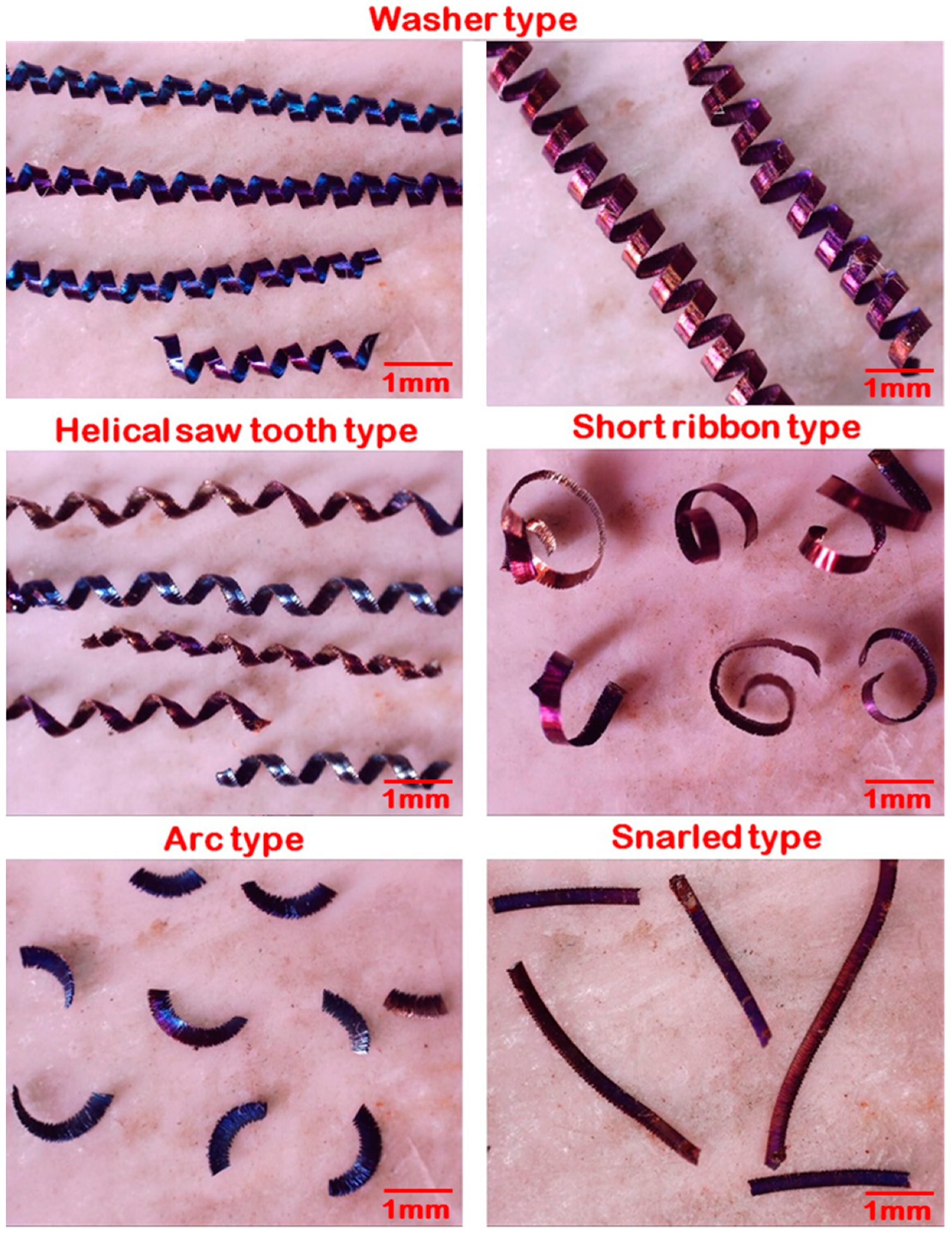
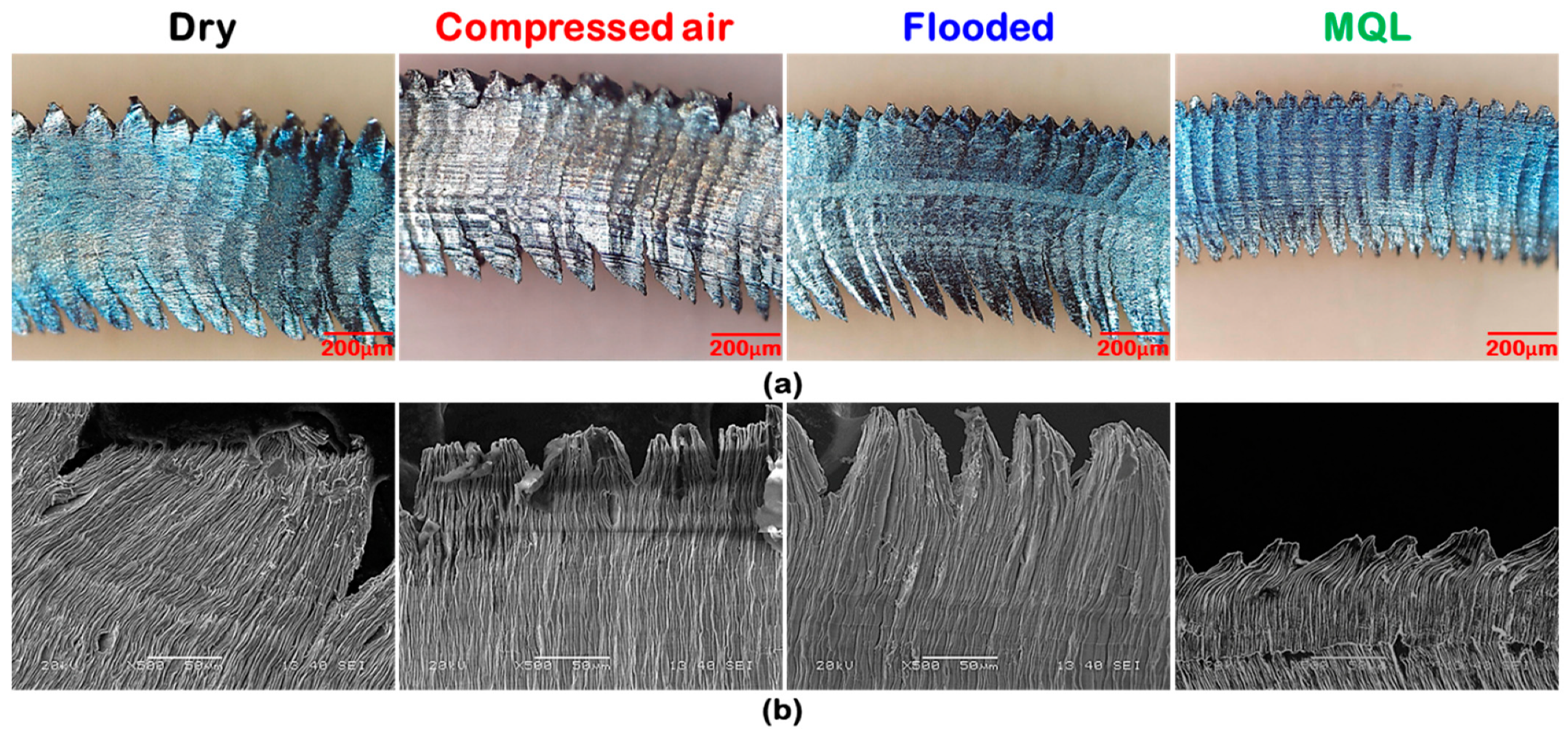
3.1. Analysis of Chip Morphology

After machining in four distinct cutting environments, the morphological aspects of cutting chips are analyzed using SEM. Serrated or saw tooth chips are noticed in all the cutting environments, as shown in Figure 4. Plastic deformation, cyclic cracks, and shear localization are the three primary attributes for the chip serration. Out of four cutting environments, chips with maximum serrations are observed for dry machining environment. More chip serration was evident at highest cutting speed (i.e., 111 m/min in dry environment). This might be due to high tool-chip friction and plastic deformation under dry cutting regime. Serration rate was considerable higher in dry cutting condition compared to other cutting conditions. This might be due to high heating load and ineffective heat transfer to the surroundings in dry cutting. That’s why in dry cutting, the plastic deformation of the workpiece might be enhanced. However, in machining under flooded and MQL environments, due to less temperature generation and better heat transfer plastic deformation might be less. As a result, side flow of material was observed in Figure 5a. Chips with slightly less serration was noticed in compressed air cooled machining while it compared with dry cutting, due to better heat transfer from the machining zones to the surrounding in convective heat transfer mode.
Chip side flow phenomenon observed normally in high temperature region. It is noticed that in high temperature region, machining became easier due to thermal softening. But due to the application of coolant in both flooded and MQL condition, hardness in both surface and sub-surface region might be enhanced. For this reason, machining became difficult for materials which were forced to move in perpendicular way to feed leads to the side flow. Chips with least serrations are observed in MQL condition. From the SEM images (Figure 5b) of chips in the dry condition, an idiosyncratic white line and dark lines called ridges and feed marks were observed correspondingly. Ridges are developed in high temperature zones and feed marks are developed in low temperature zones. More heat generated in both dry and compressed air machining. Heat distribution might be non-uniform due to ineffective heat transfer. That is why the above phenomenon noticed particularly in dry cutting condition. Machining performance was enhanced when machining was accomplished with flooded and MQL condition. Drastic change in terms of chip serration diminishment was observed.

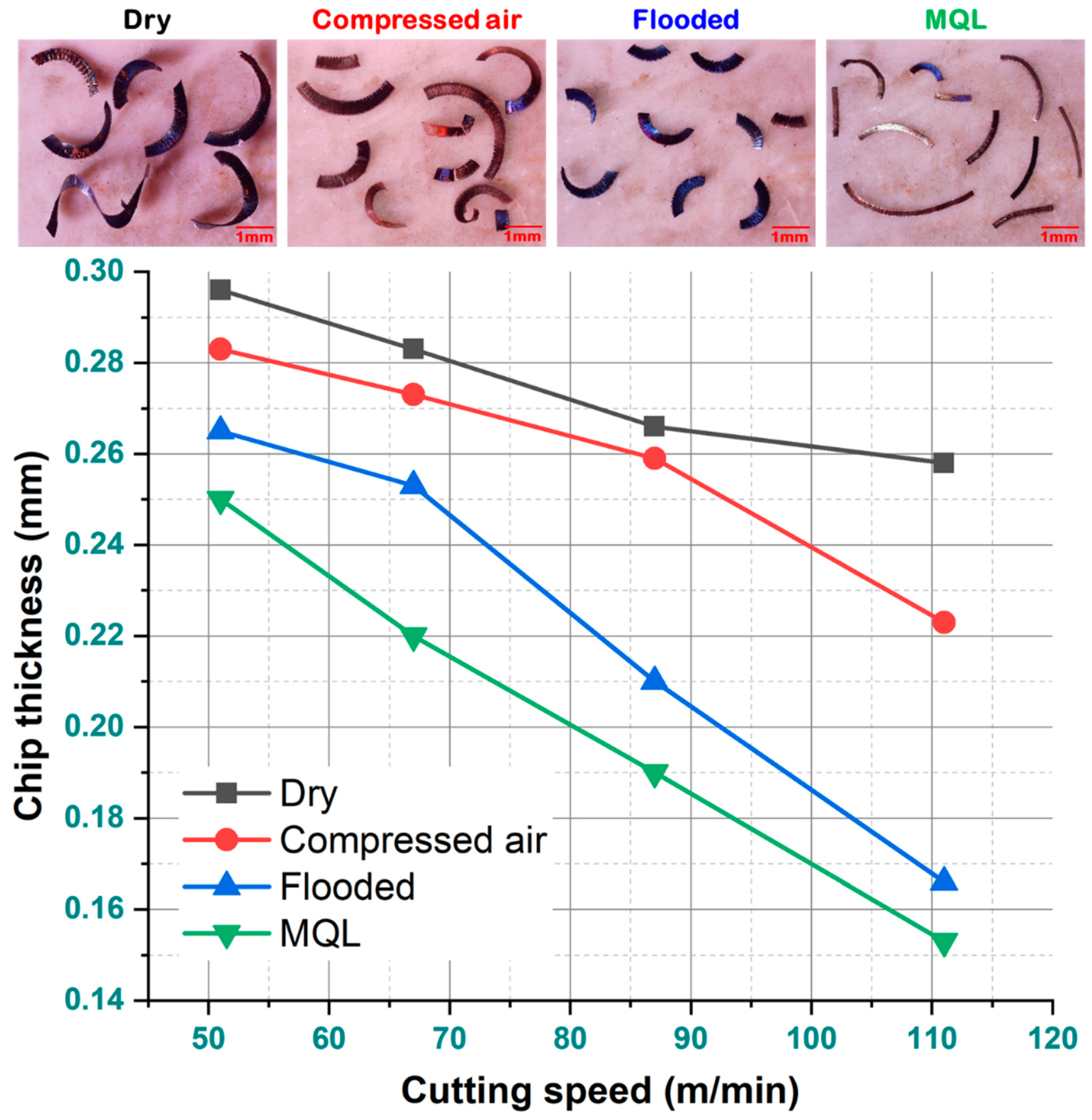
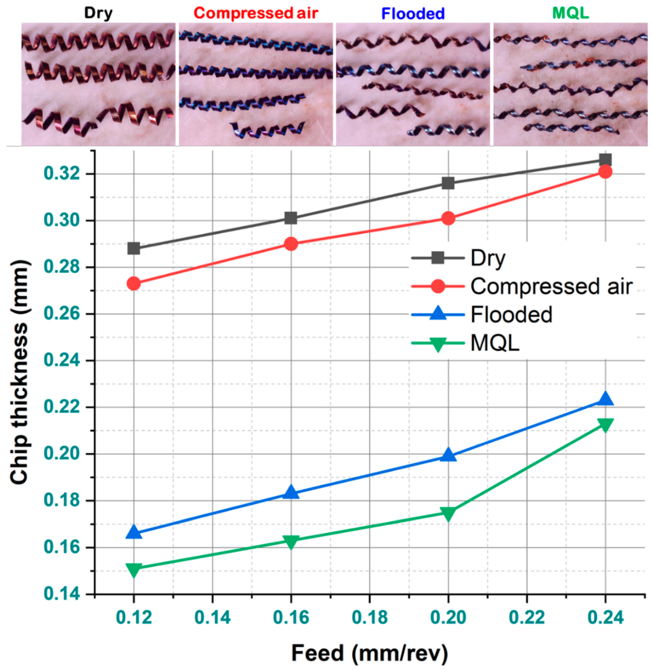
3.2. Analysis on Chip Thickness

Metal cutting process is associated with the generation of high heat at the shear zone which leads to thermal softening of tool and work material. As compared to tool material the material of workpiece became more softer, as a result it generally produces helical and continuous types of chip. In the present study, the thickness of chip obtained in dry cutting was more as compared to other three considered cooling-lubrication methods (i.e., compressed air-cooled, flooded, and MQL). Wear on rake surface (called crater wear) greatly depends upon the secondary deformation characteristics of chip. In dry cutting, severe wear on rake surface due to high friction between tool and chip and secondary deformation of chip surface. Better heat dissipation might be occurred in compressed air machining condition compared to dry cutting. Thus, better results are noticed compared to dry machining. Moreover, in flooded cutting condition, as the cooling was not effective, wetting of less surface area and ineffective penetration of cutting fluid in different machining zones with respect to MQL, chip thickness was found to be little bit larger but better result was achieved in terms of chip thickness compared to compressed air and dry conditions. Additionally, the flow ability of chips on the rake surface plays a major role in chip thickness decrement. In flooded and MQL cutting, due to application of coolant, agglomeration of chips on the rake surface was not observed resulting thinner chips. Chips produced in dry cutting conditions are in highly heated state due to the absence of effective cooling medium. In case of dry and compressed air-cooled conditions, some agglomeration of chips was present. This might affect the chips’ thickness. Moreover, the movement of hot flowing chip along the rake face of cutting insert it may weld to the rake surface and sometimes the back surface of flowing chips in contact with tool rake surface may carry away some tool material by the phenomena of diffusion. Thus, thicker chips with high curled radius are observed in dry cutting condition while thinner chips with smooth surface and more curled radius are observed in MQL condition, as compared to other cutting environments. Since in MQL condition the cutting fluid is applied by means of fine nano-mist particles at high pressure and velocity to the different friction interface zones, which formed a thin layer of hydrodynamic film at the interface of flowing chip and tool’s rake face. This hydrodynamic film of cutting fluid tends to push away the heated flowing chip from rake face of cutting insert. In addition, it also prevents the sticking of chip back surface to the rake face, and simultaneously preventing the welding of chip material to the rake face resulting smaller chip thickness.
It was obvious from Figure 6 that the chip thickness reduced with cutting speed under all the cutting environments. At low cutting speed, thickness of the chip found to be higher. However, as the speed progresses, it was found to be lower. This might be related to the development of built-up-edge. BUE influences both tool-chip friction and rake angle of cutting tool, for which chip thickness might be affected. Reduction of cutting force might be another reason for decrement in chip thickness as the heat transfer from machining zone to the surroundings is not effective at high cutting speed resulting from lack of contact time and thereby, resulting in thinner chips. From the graphical representation in Figure 7, it was observed that the chip thickness increased with feed under all cutting environments. During dry machining as well as compressed air-cooled machining, self-excited vibration was experienced whereas in flooded and MQL, the vibration reduced gradually. Vibration influences the tool wear. Hence, more chip thickness might be observed in dry cutting due to vibration. The increase in chip thickness resulted from the increase in the shear plane area. Consequently, the increase in feed rate enhances the cutting force which promote the formation of periodic chip which results in increase in chip thickness. In dry machining, more tool wear was observed due to which cutting force increased which resulting more shear plane area and more undeformed chip thickness. However, in MQL, less tool wear so less force and minimal chip thickness noticed. In compressed air machining, tool wear was somehow reduced compared to dry cutting. Therefore, better results observed in terms of chip thickness. In flooded cooling, thinner chips observed compared to dry and compressed air condition. But due to ineffective penetration of coolant in various machining zones, both cooling and lubrication might not be influential compared to MQL resulting somehow thicker chips respect to MQL.

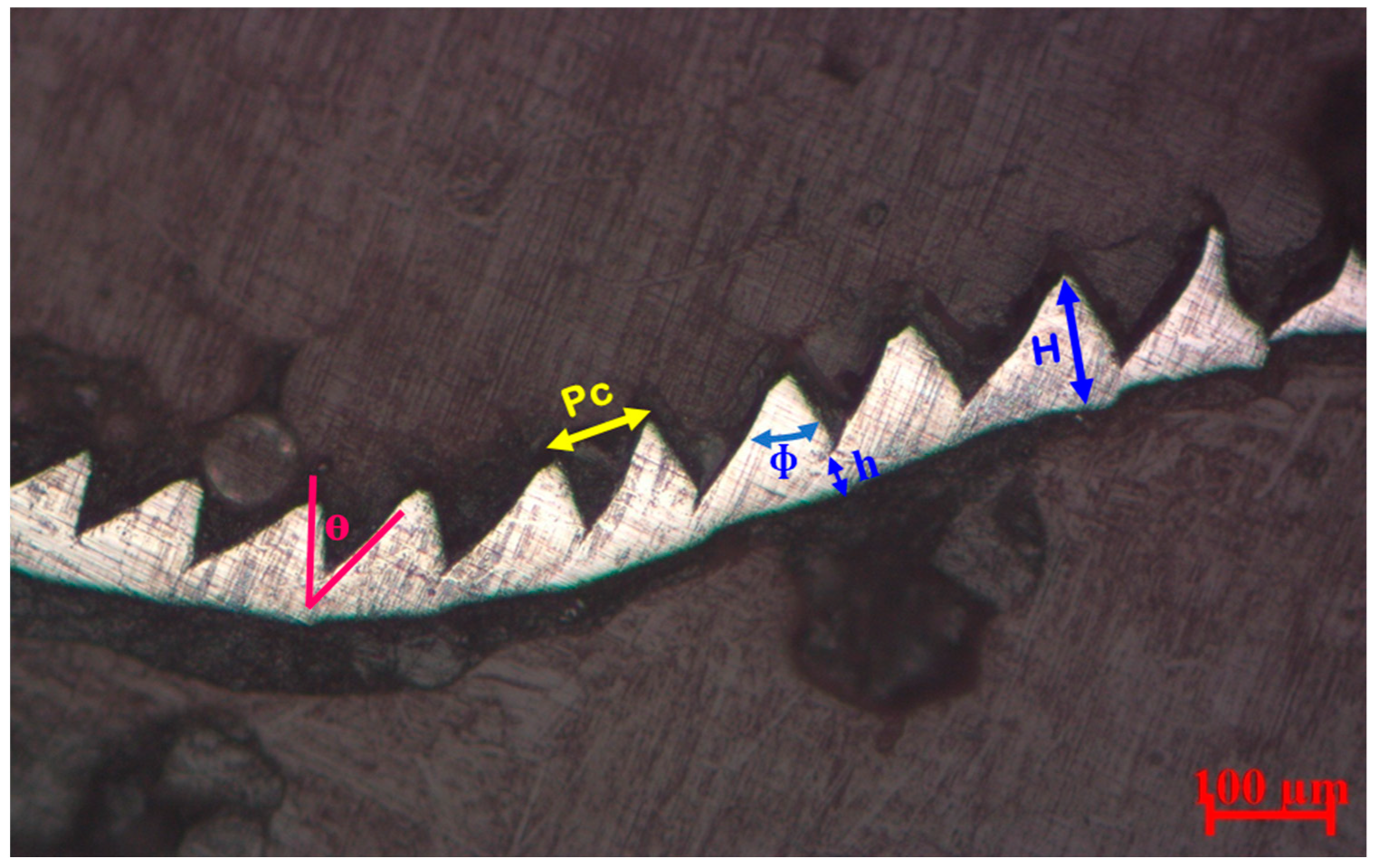
3.3. Analysis on Chip Saw Tooth Distance

There are two most important chip characteristics are the saw tooth or serrated chips (i.e., saw tooth distance and chip segmentation frequency). The saw tooth distance of a serrated chip is denoted by the longitudinal distance in between two successive point on a saw-toothed chip profile. There is an inverse relationship between saw tooth distance and chip segmentation frequency. Both the chip characteristics are affected mainly by four factors (i.e., strain rate, strain hardening, thermal softening, and shear deformation) occurred at the primary deformation zone. In addition, saw tooth distance is highly influenced by two attributes of tool life and deformation rate of chips. While observing the morphology of serrated chips with respect to various cooling-lubrication environments, higher value of pitch was observed for dry cutting due to high cutting zone temperature and high strain rate along with thermal softening of work material results in high material deformation. However, minimum saw tooth distance was noticed in MQL environment due to the proper lubrication it lowers the thermal softening of work material. Moreover, this decrement in saw tooth distance might be due to less tool wear and less friction and heat generation due to effective cooling and lubrication by MQL. For better illustration, it is possible to observe from Figure 8 that the changing law of tool wear is closely associated with the serrated type saw tooth chip formation. That is, with changing of C/L technique from MQL to dry, follows prominent shape of saw tooth chip, is the evidence of burr formation (caused by intensive shear bands) which develops friction at tool-work interface caused by abrading nature of serrated edge of chip on tool edge. Thereby, grooves formed on flank face of tool at higher cutting speed.
For all the four cutting conditions, it was observed from Figure 9 that with cutting speed advancement, saw tooth distance increases. Due of inadequate contact time at higher cutting speeds, the heat dissipation is relatively low. The chip serration decreases as heat dissipation improves, and the tooth closeness rises. Thus, the width of sawtooth chip grows as the amount of heat generated during machining increases with the increase in cutting speed. This may be attributed to strain rate as well as tool wear, where a decrease may be explained by thermal softening effect. Since the application of coolant in machining has the capability to restrict strain rate which results in less flank wear, and saw-tooth width. At low cutting speeds, the effects of thermal softening or strain hardening are less prominent than at high cutting speeds. Thus, increase in saw-tooth distance at high cutting speed was due to the increased flank wear and increase in strain hardening. In the similar context from the Figure 10, it was noticed that with feed, the saw tooth distance increased for all the cutting environments. This can be attributed to more and continuous contact between tool and work, friction and material adhesion.

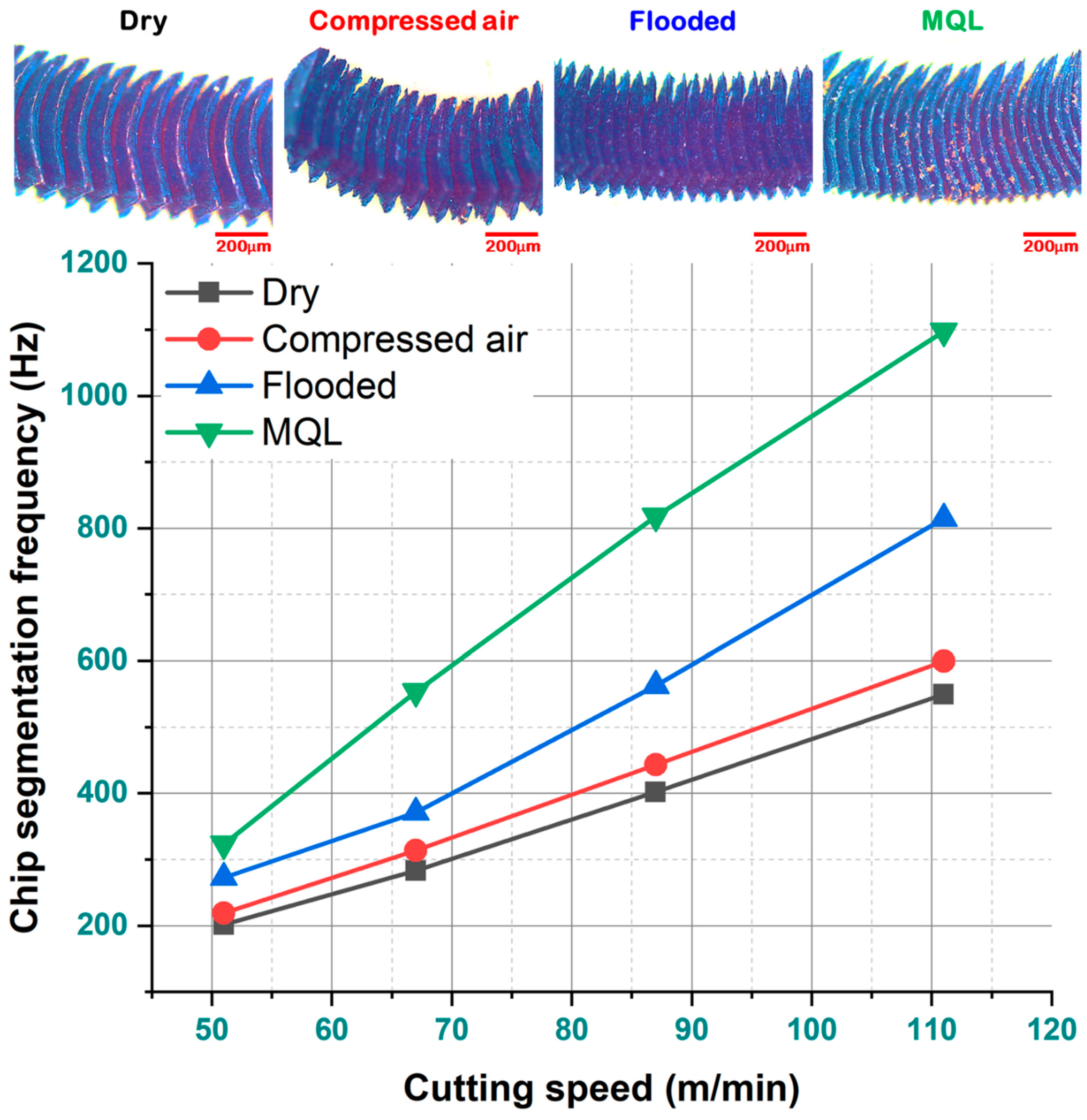
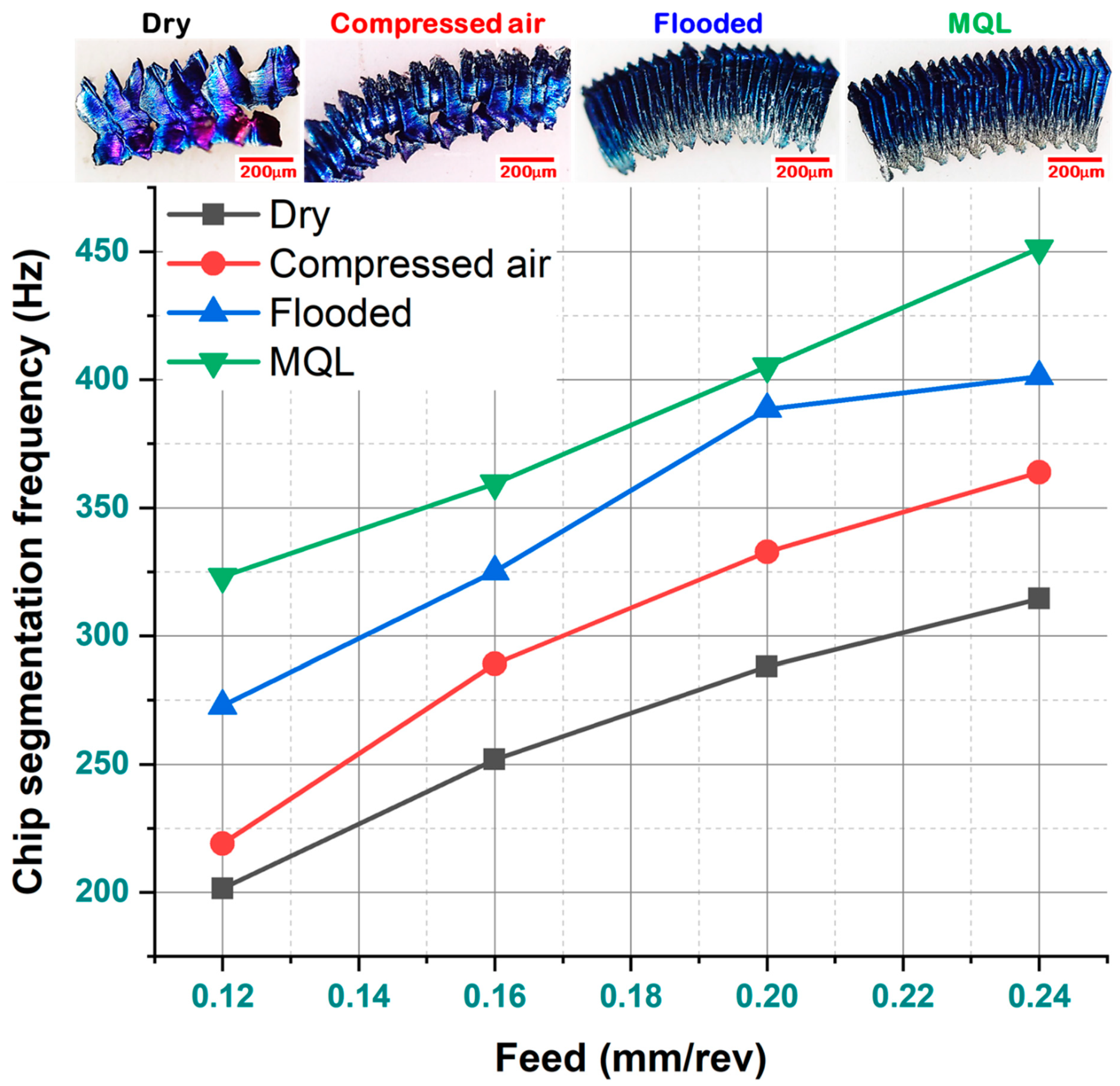
3.4. Analysis on Chip Segmentation Frequency

For difficult to machine materials, the chip segmentation mechanism is quite important (since chip formation depends upon chip segmentation). Moreover, it affects the chip fragmentation by which both chip evacuation and chip flow can be easily controlled during machining. After conducting the experiments, chips are collected and the selected chips are polished with decreasing grades of polishing papers. Then, samples are viewed through the metallographic microscope and measurements are taken for various characteristics such as segmentation spacing or pitch (Pc), equivalent chip thickness, saw tooth included angle (ϕ), shear angle (θ), and chip segmentation frequency, etc. For the diminishment of experimental error, each reading was taken two to three times, and then the mean value was considered as final. A sample view of polished chip for microscopic analysis is shown in Figure 11. In the present study, the chip segmentation was determined in terms of chip segmentation frequency which is basically the reciprocal of saw tooth distance value. The chip segmentation frequency (Fch) was calculated by using following formula.
F ch = 100 × f × a p × V C   6 × P c
where VC is the chip flow velocity in m/min, f is the feed rate in mm/rev, ap is the depth of cut in mm, and Pc is the saw tooth distance in µm.
The degree of deformation is a dominant factor for chip segmentation frequency. A higher rate of chip segmentation was reported in MQL condition as compared to others C/L environment. In the MQL condition, as the base coolant is applied to the cutting zone it develops a hydrodynamic layer of cutting fluid between the rake face and chip, exerting force over the chip and enhancing the chip breakability. Subsequently, due to the excellent cooling capability of MQL on the thinner chip, it probably forms a higher thermal gradient along the thickness of chip. Therefore, the continuous chips tend to be more curved and segmented into smaller section. While the segmentation frequency is less in dry cutting compared to other cooling strategies due to material adhesion, chip sticking and BUE formation in the absence of proper lubrication system.
Chip segmentation frequency followed an increasing trend with an increase in cutting velocity when feed and depth of cut were kept constant (as illustrated in Figure 12). Theoretically, with an increase in cutting speed the rate of strain and shear deformation tends to increase in the primary deformation zone. The energy used during shear deformation of uncut chip is converted into heat energy in machining process. But when machining is performed with high speed, it gets very short time for chip deformation, hence effective dissipation of cutting heat becomes very difficult which cause adiabatic shearing followed chip breakage. Chip segmentation frequency is nearly equal to the frequency of cutting force variation. So, high magnitude fluctuation in cutting force along with severe shear deformation due to the high cutting zone temperature results in increasing chip segmentation frequency in primary plastic deformation zone. The effect of axial feed on chip segmentation frequency is illustrated in Figure 13. From the figure, it was observed that chip segmentation frequency followed an increasing trend with increase in feed rate in all cutting condition when cutting speed and depth of cut were kept constant. With the increase of feed rate, the friction between chip and tool increases resulting rise in localized temperature which promotes shear cracking of chip. Thakur and Gangopadhyay [24] reported that chip segmentation frequency increased with cutting speed as the saw-tooth spacing decreases in serrated chip. With feed, an increasing trend of chip segmentation frequency was observed highest frequency was observed in the MQL condition and least frequency was observed in dry condition.
Shear angle and saw tooth included angle are the two important chip characteristics. The saw tooth included angle is the angle formed at the saw tooth projection at the deformed part of the chips. The saw tooth included was more with the MQL cutting compared to other cutting conditions due to the low temperature generation at the interface. In general, the shear plane angle is the angle on which chip starts separating from the workpiece in the direction of the cutting velocity vector. The angle between the shear band and the normal drawn parallel to the chip height in that shear plane can be considered as shear angle. The thickness of the chip is related with the shear angle also, which decides the coefficient friction between the two surfaces which are in contact. In the present case, the shear angle was determined with the help of microscope after polishing of the chips. The shear angle was found to be higher for MQL condition due to the reduced contact length between chip surface and rake surface of the insert. Also, the chip thickness affects the shear angle. The less the thickness observed in the MQL, the greater the shear angle was observed compared to other machining conditions.

3.5. Economic Analysis

In machining operation, economic activity plays a vital role in improving production rate as well as product quality. Innovation, exploration, planning, and the use of resources are still being attempted to ensure the machining process more effectively, efficiently, commercially sustainable, and environmentally safe. This involves knowledge or consciousness of the factors which control or influence the machining economy and how it operates. For example, enhancement of both MRR and surface finish requires machining at high cutting speed but it raises the possibility of frequent of cutting tools (edges) as a result of rapid tool wear caused by increased cutting temperatures, are substantially controlled by proper cutting fluid application. However, cutting fluid not only favorably reduces cutting temperature, friction and tool wear in machining but also causes severe environmental pollution and health hazards, which is a tremendous social problem in addition to other technical and financial problems. Therefore, both economic and environment friendliness need to be explored while planning and carrying out the machining operation. In view of high speed machining which supports high production rate, an economic assessment is executed for different cutting environments.
For this reason, further experimental trial run were performed under various cutting environments coupled with similar machining settings for to determine the tool life of SiAlON ceramic cutting insert. By taking into consideration of ISO 3685 (i.e., flank wear VB till 0.3 mm), one more experiment was performed for each precited C/L condition by setting cutting speed and feed at their higher limit (i.e., v = 111 m/min and f = 0.24 mm/rev) and ap at 0.4 mm for estimating tool life of SiAlON ceramic cutting insert. Figure 14 illustrates the development of flank wear and VB with machining duration up to tool life of SiAlON ceramic tool under different cutting environments. Effective cooling-lubrication capability by MQL technique results in improvement of tool life. Machining under above four precited C/L conditions experience the tool life of 34 min, 47 min, 73 min, and 81 min, respectively. This obtained results show that the tool life in turning in MQL are 138%, 72% and 11% greater than dry, compressed air, and flooded conditions, respectively. For economic justification in machining applying the various cooling-lubrication environments (compressed air, dry, flood, MQL), a comparison assessment was proceeded based on overall machining cost per component considering both direct and indirect cost associated with machining according to Gilbert’s approach [25,26], as shown in Table 2. The cost analysis results reveal that the utilization of SiAlON ceramic tool is more economically viable under MQL condition as the overall machining cost per component is lower ($0.27) as compared to dry ($0.36), compressed air ($0.31), and flooded ($0.29) machining conditions. So, cost saving can be attained when using SiAlON ceramic tool in MQL condition.

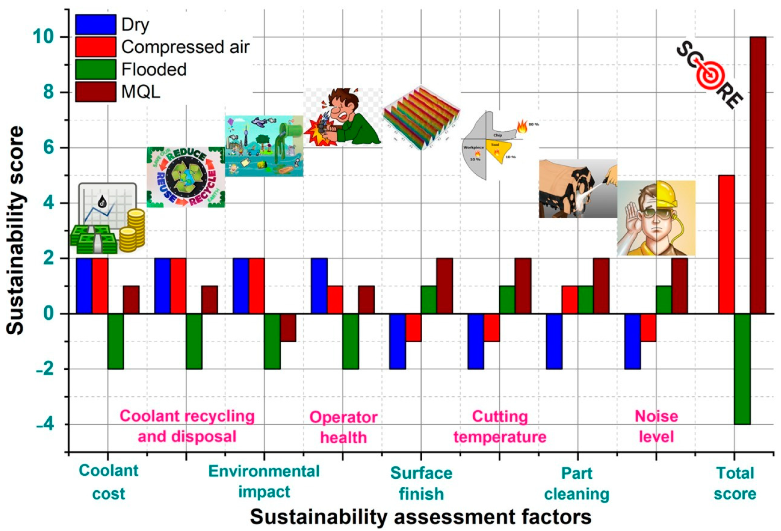
3.6. Sustainability Assessment

Due to strict regulation of government policies and manufacturing constraints with regard to state of affairs in cleaner production, sustainability assessment of every production methodology performs a key aspect prior to its actual practice in industry. Nowadays, sustainable manufacturing has increasingly attracted attention in various industries as it minimizes or eliminates processing and production wastes using eco-efficient practice and new environmental technology. All levels of manufacturing activities (product, process, and system) promise a long-term benefit in environmental, social and economic point of views as it manufactures the products using non-polluting and natural resources conserving economically sound and safe process. This work considers eight major sustainability factors (surface finish, cutting temperature, noise level, coolant cost, coolant recycling and disposal, part cleaning, environmental effect, and operator health) for comparative analysis under dry, compressed air, and wet (flood and MQL) machining cooling-lubrication environment by concerning the aspects associated with technical, ecological and economical point of view. For achieving the sustainability needs, an efficient decision-making approach called Pugh matrix (refer, Table 3) is proposed by assigning the weightage score to above stated sustainable parameters in a mathematical number (in the range of −2 to +2) based on its importance i.e., worst-to-best criterion. Here, score “0” was considered as baseline and “+1” and “−1” were allocated for better and worse than reference, while “+2” was assigned for much better and “−2” for worst alternatives. For each C/L strategy, all assigned values are at last added. The technique which obtained maximum value is chosen as the best criteria.
Wet machining provides sufficient cooling and lubrication at various machining interface pairs (work/tool and tool/chip) to reduce friction, which is a great improvement in reduction of cutting temperature as compared to dry machining. When the flood cooling is used, the mean temperature is reduced by some degree (but not by much). It has already been reported by many researchers that the low pressure of flood cooling is incapable to overcome the barrier to penetrate into the chip-tool and tool-work interfaces. However, in MQL machining, impressive temperatures are reached due to the fact that MQL upon impingement is distributed as numerous coolant droplets mixed in compressed air and hit on the hot cutting zone (i.e., on the chips, tool, and work surface). These droplets have higher heat absorption capability than the abundantly flowed coolant in flood cooling. Moreover, these droplets due to their tiny size are capable of penetrating the interfaces. Therefore, generated heat is absorbed as the latent of vaporization of the cutting fluid. Consequently, the cutting zone temperature is reduced, as reported by Mia et al. [27] and Panday et al. [14]. Thus, for cutting temperature and surface roughness criteria, a highest weightage score of ‘2’ is assigned to MQL machining, as here cutting fluid is applied at high-speed high pressure, it effectively removes heat from cutting zone and simultaneously control the development of thermal stress, resulting in good surface quality. The lowest weightage score was ‘−2’ in the case of dry machining. In comparison to conventional wet (flood and MQL) machining system, due to improper lubrication and lack of coolant in dry machining condition attends high interface (cutting) temperature. While “+1” score was provided to flooded condition as coolant reduces the cutting zone temperature and also improve surface quality. In the case of the CA condition, these criteria got a score of “−1” as high heat is generated since the friction and surface quality obtained is also poor.
In wet machining, the extensive application of cutting fluid aims to improve machining performance as well as machinability. However, their use can be an additional financial burden (up to 25% of total machining cost per component). In dry machining, as no cutting fluid is used, the cost associated with coolant is not considerable. To assess the sustainability score of coolant cost criteria, a highest weightage score of “+2” score was allocated to both dry and CA conditions due to the absence of cutting fluid, while the lowest weightage score of “−2” weightage in case of flooded condition due to the usages of excess amount of cutting fluid. Whereas in view of MQL, “+1” weightage was given due to involvement of almost negligible amount of cutting fluid.
Additionally, the recycling and disposal used cutting fluid are evident as sufficient pressure (i) due to requirement of filtration and repetitive cleaning of expensive coolant after several machining cycles; and (ii) due to serious negative impact to environment. This leads to an additional processing equipment cost for extraction of contaminants from used coolant and poor efficient for eco-friendly machining. However, in machining under dry and compressed air-cooled environments, no such things are required as no cutting fluid is used. This fact was accordingly conveyed to dry and CA machining of score ‘+2’ while “+1” score was given to MQL as it involves with very little coolant in machining system. During the assessment of recycling and disposal of the coolant criterion, “−2” score was provided to flooded condition, as usage of large quantity of coolant required repeated cleaning and filtering to reuse that coolant. In addition, before disposing used coolant, it requires specific treatment to minimize its harmful effect to the environment. Hence, it increases the coolant handling cost.
In the case of part cleaning criterion, a score of “+2” was assigned to MQL, “−2” to dry and “+1” score to CA as well as flooded cutting environment. Cost associated with part cleaning is comparatively high in dry cutting as no cutting fluid is used, the chip and debris particle remain stick to the worked surface after machining. With the presence of coolant in wet condition and use of compressed air in CA condition, the chips and debris are flushed out from cutting zone and surface of the part. So, the part requires very less cleaning after machining in the case of CA and flooded conditions. Furthermore, in MQL the cutting fluid mixed with high-speed high pressure compressed air effectively remove all debris, chips micro-chips from cutting zone as well as worked surface, so it does not require any post cleaning operation.
During dry machining, it is thought to have larger centrifugal force accelerating cutting tool wear that pertains to higher vibration amplitudes compared to wet machining conditions. However, in wet machining conditions the necessary coolant plays a major role to attenuate the noise levels on account of lesser friction and thermal shock loads, which avoids unacceptable exertions of workpiece surface (thus minimizing thermal and vibrational shocks). Taking into consideration of noise level for sustainability assessment, “−2” and “−1” scores were, respectively, assigned to dry cutting and compressed air-cooled C/L strategies as high friction is generated at cutting zone during machining process due to the lack of lubrication resulting high noise generation throughout the operation. While, usage of coolant in MQL and flooded condition provide better lubrication which effectively reduce the friction and cutting force resulting reduction in noise production. Hence, in MQL machining a weightage score “+2” is assigned to judge the sustainable performance which is better than flooded machining possessing a score of “+1” as here lubrication is more effective compared to above there mentioned process.
Without the use of metal, the working fluid offers a cleaner as well as safer environmental approach for machining of hardened steel. In case of wet machining, it leads to undesirable occupational operator health and environment friendly situation due to poor biodegradability of cutting fluid and hazardous chemical constituents’ emissions. Due to the absence of cutting fluid in both dry and compressed air-cooled methods, so there is no emission of any harmful gases. Therefore, a highest weightage score of ‘2’ is assigned to both dry and compressed air-cooled machining. The coolant used in machining process contains many harmful chemical ingredients which liberate harmful emission during machining process due to the involvement of high cutting heat. Thus, a weightage of “−2” was allocated to flooded condition as large amount of coolant was used in it. On the other hand, MQL was allocated with “−1” weightage, as much less coolant with high speed and high pressure is used in this condition, which results in very less hazardous emission.
To assess the sustainability score for operator health, the exposure of the operator to harmful emission has been considered. A score of “+2” was given to the dry condition as no fluid is used here (hence no generation of harmful gases). The weightage score “+1” was assigned to CA as it used air at compressed form which contain oxygen, which may perform oxidation of harmful gases during cutting operation. MQL also assigned with a score of “+1”as it involves very less cutting fluid. Meanwhile, the flooded condition produces large quantity of hazardous emission due to the usage of large quantity of coolant. Thus, it deserves a score of “−2”.
To avoid the misleading conclusion, a comparative study is performed for the cutting performance evaluation of four different cooling-lubrication conditions (dry, compressed air, flooded and MQL) using same experimental setup at v = 111 m/min, f = 0.24 mm/rev and ap at 0.4 mm. Cutting force (Fc) is measured with the 9257B piezoelectric dynamometer manufactured by Kistler. A roughness tester (model: Surftest SJ-210, manufactured by Mitutoyo) is employed to measure the roughness value (Ra) of machined component. Figure 15 shows the optical micrographs and cutting force signal images which are illustrating the various machining attributes using stated above C/L conditions. From the analysis, it is to be noted that out of four C/L techniques, MQL promises better machining performance in terms of improved surface finish, minimum cutting force, and lower flank wear.
After overall calculation of allocated weightage score of all considered sustainability parameters, it is observed that the MQL condition outperformed the superior result (i.e., total score of 10), followed by CA (5), dry (0), and lastly by the flooded condition (−4). The assessment results are illustrated in Figure 16. In brief, the MQL condition contributes towards a safer and cleaner approach of environment friendly machining to improve sustainability. It is evident that machining under dry and compressed air-cooled environment condition is workable if and only if high temperature does not interface any other machinability performances. Further extensive research is necessary before such a decision is made.

4. Conclusions

The present paper concerns with the performance effectiveness of various cutting environments in finish turning of Nitronic 60 alloy steel with new generation SiAlON ceramic insert in terms of various chip characteristics (chip morphology, saw tooth distance, chip thickness, and chip segmentation frequency). Novel aspects of the present work include: (i) enhancing the heat capacity using sprayed-jet form by the MQL technique in order to improve the machining performance; (ii) bringing our investigations towards the efficiency of various cooling-lubrication strategies during machining for their suitability of application towards sustainable manufacturing in industrial sectors; (iii) proposing an alternative of costlier CBN tool by utilizing new-generation SiAlON ceramic tool in finish turning process from techno-economical perspective, which is helpful and efficient from industrial point of view; (iv) offering an environmental friendly, safer, and cleaner production strategy for machining of hard-to-cut as well as difficult-to-cut materials; (v) helping to improve the desirable chip formation; and (vi) serving as a source of knowledge for the development of a common language for sustainable manufacturing in both research field and industrial practice. The following conclusions can be drawn from the present work.
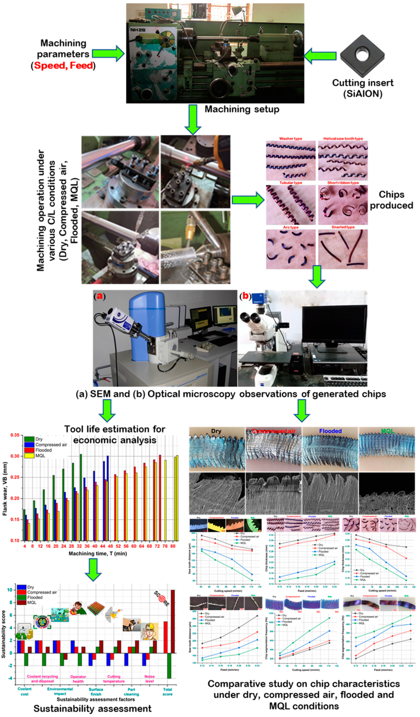
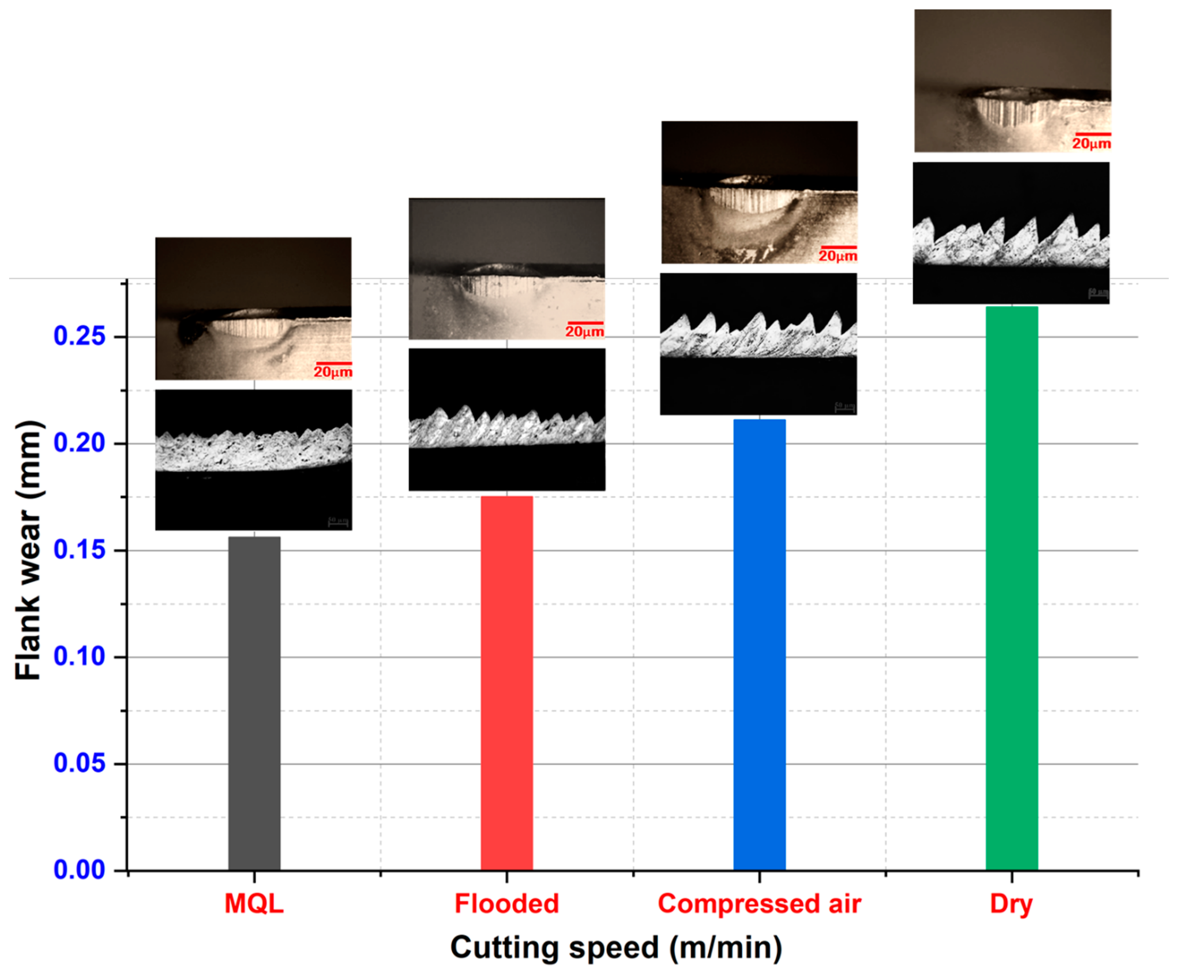
  • Out of the four cutting environments, it can be concluded that machining with MQL relatively performed well as compared to above three precited C/L conditions.
  • Based upon the experimental analysis, as in the MQL condition, cutting fluid is applied to the nano-mist particles in a spray jet form. It offers an effective cooling- lubrication approach at the machining zone and outperformed better regarding (i) chip characteristics due to less heat generation as well as friction, (ii) longer tool life, and (iii) considerable economic advantages.
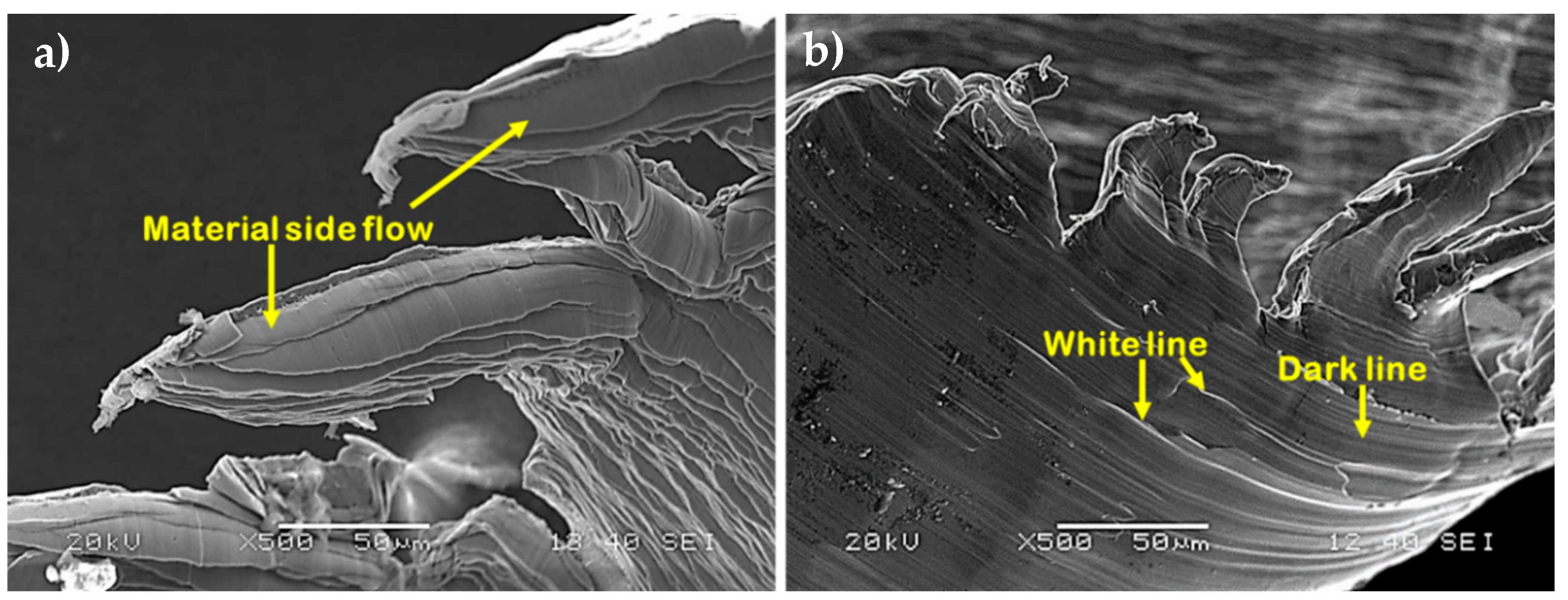
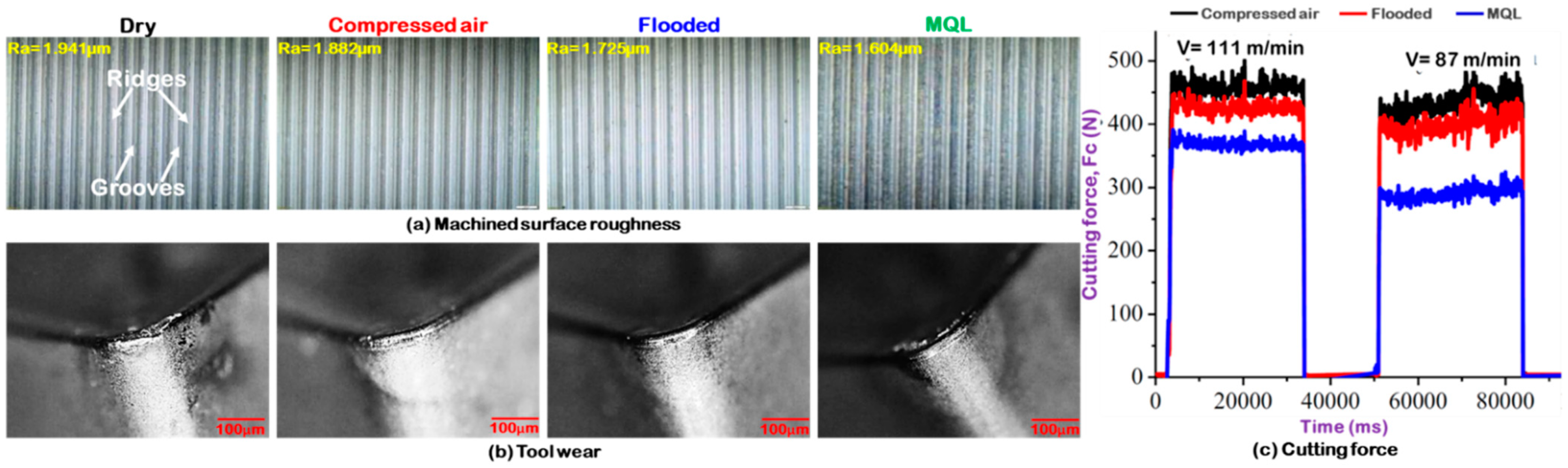
  • Less serrated chips are observed during MQL machining. Side flow of material was observed with MQL and flooded coolant condition. Ridges and feed marks are detected on chip surface in the dry cutting condition. In MQL machining, no such marks are observed.
  • Decrement of chip thickness was observed with cutting speed for all the cutting environments. Thinner chips are observed in MQL. Chips with the highest thickness were noticed in dry cutting condition. Better performance was observed in the flooded condition with respect to both dry and compressed air.
  • With feed, an increment in chip thickness was found for all the cutting conditions. The highest chip thickness was observed for dry cutting and least was observed for MQL condition. With increment in feed, self-excited vibration was noticed in dry and compressed air so that leads to more tool wear resulting thicker chips. In MQL and flooded cooling, the vibration was reduced due to coolant application which leads to less tool wear (causing thinner chips).
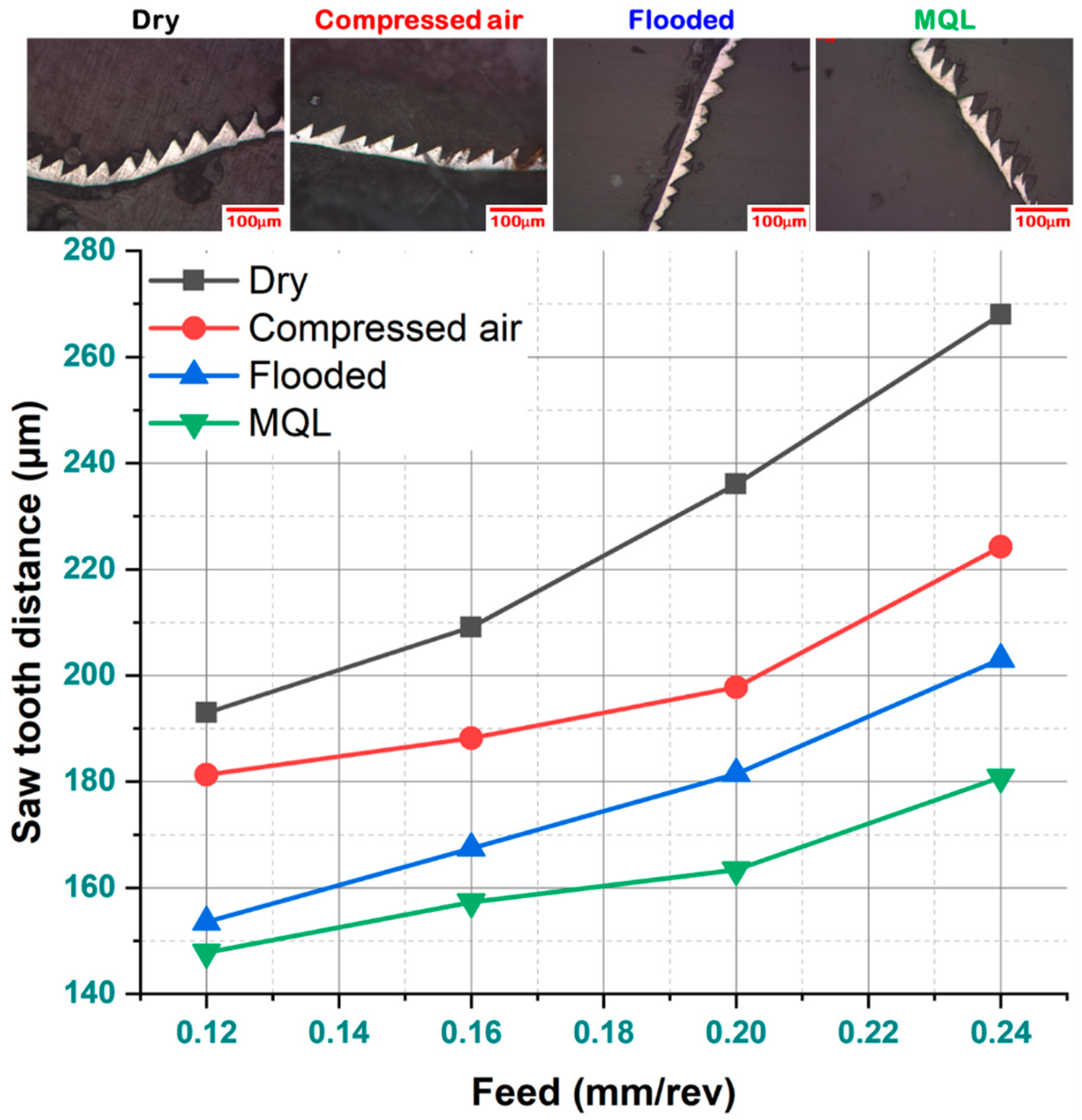
  • In MQL condition, chips with less saw tooth distance were observed, while in dry cutting, chips with a greater saw tooth distance were observed. With cutting speed, saw tooth distance increased for all the cutting conditions. Due to the effectiveness of cooling and lubrication in MQL, better results were achieved.
  • The frequency of the chip segmentation is reciprocal of saw tooth distance. As the saw tooth distance was greater in dry cutting, less frequency was observed. In the MQL condition, more chip segmentation frequency was noticed. This might be due to less tool wear, nominal material adhesion, and BUE formation.
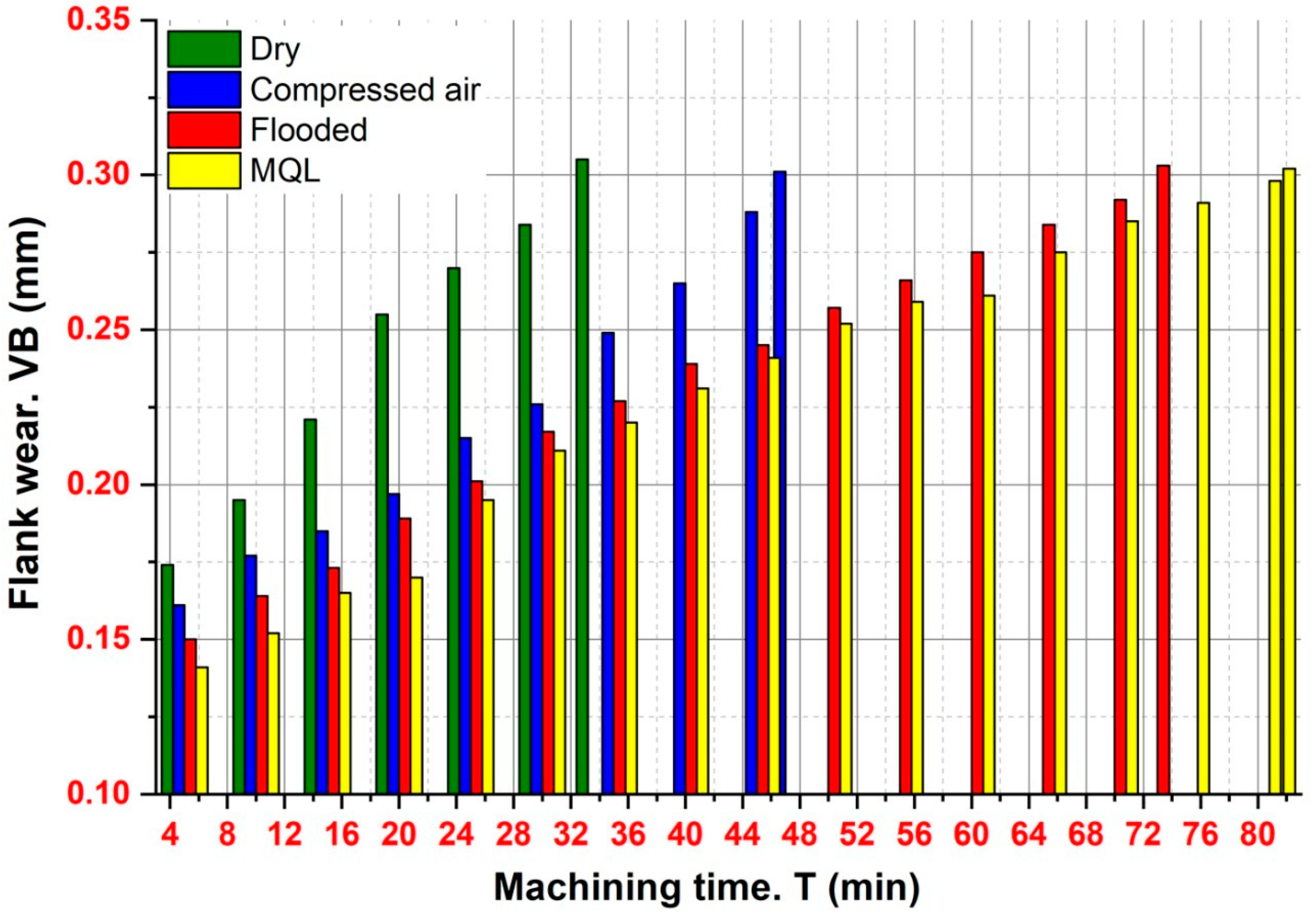
  • During the investigation, a tool life of 81 min was recorded for the MQL condition, whereas it was found to be 34 min, 47 min, and 73 min in the case of dry cutting, compressed air-cooled, and flooded conditions, respectively. Result shows that the tool life under MQL machining is 138%, 72%, and 11% greater than the dry, compressed air, flooded conditions, respectively. The use of a SiAlON ceramic tool results in a more economically viable method under the MQL environment as the overall machining cost per component is lower ($0.27) as compared to dry ($0.36), compressed air ($0.31), and flooded ($0.29) machining conditions.
  • Compared with compressed air-cooled, dry and flooded cooling strategy, machining under MQL condition provides environment friendliness, and is both technologically viable and economically feasible for improving sustainability.
  • The application of ecofriendly radiator coolant in the form of pressurized coolant jet is implementable and preferable over dry as well as flooded machining, attributed to the sufficient cooling and lubrication effects designed to reduce the friction at tool–workpiece contact point created by MQL.
  • In terms of future work, this study can be extended to include the application of other different cooling-lubrication (C/L) methods such as spray impingement cooling, nanofluid assisted MQL, and cryogenic cooling to compare the effectiveness of different C/L approaches towards machinability improvement. Moreover, the comprehensive study on power consumption, surface roughness, tool wear, and cutting force analysis will be thoroughly discussed in the future to physically understand the machinability performance of Nitronic 60 under these C/L techniques. An attempt on modeling, and then the optimization of machining performance characteristics, represents scope of future work for machinability improvement and for comprehensive understanding of the selection of appropriate cooling techniques and cutting conditions.

Author Contributions

All authors contributed equally in this work. A.D., S.P., S.R.D., M.S.A., A.M.M.I. and A.E. conceived and designed the experiments; A.D., S.P., S.R.D., M.S.A., A.M.M.I. and A.E. performed the experiments; A.D., S.P., S.R.D., M.S.A., A.M.M.I. and A.E. analyzed the data; A.D., S.P., S.R.D., M.S.A., A.M.M.I. and A.E. contributed reagents/materials/analysis tools; A.D., S.P., S.R.D., M.S.A., A.M.M.I. and A.E. wrote the paper. All authors have read and agreed to the published version of the manuscript.

Funding

This research received no external funding.

Data Availability Statement

Not applicable.

Conflicts of Interest

The authors declare no conflict of interest.

References

  1. Zhao, C.; Stewart, D.; Jiang, J.; Dunne, F.P. A comparative assessment of iron and cobalt-based hard-facing alloy deformation using HR-EBSD and HR-DIC. Acta Mater. 2018, 159, 173–186. [Google Scholar] [CrossRef]
  2. Ahmadein, M.; Elsheikh, A.H.; Alsaleh, N.A. Modeling of cooling and heat conduction in permanent mold casting process. Alex. Eng. J. 2021, 61, 1757–1768. [Google Scholar] [CrossRef]
  3. Zhou, H.; Wu, C.; Tang, D.-y.; Shi, X.; Xue, Y.; Huang, Q.; Zhang, J.; Elsheikh, A.H.; Ibrahim, A.M.M. Tribological Performance of Gradient Ag-Multilayer Graphene/TC4 Alloy Self-Lubricating Composites Prepared By Laser Additive Manufacturing. Tribol. Trans. 2021, 1–11. [Google Scholar] [CrossRef]
  4. Ahmadein, M.; El-Kady, O.A.; Mohammed, M.M.; Essa, F.A.; Alsaleh, N.A.; Djuansjah, J.; Elsheikh, A.H. Improving the mechanical properties and coefficient of thermal expansion of molybdenum-reinforced copper using powder metallurgy. Mater. Res. Express 2021, 8, 096502. [Google Scholar] [CrossRef]
  5. Elsheikh, A.H.; Guo, J.; Huang, Y.; Ji, J.; Lee, K.-M. Temperature field sensing of a thin-wall component during machining: Numerical and experimental investigations. Int. J. Heat Mass Transf. 2018, 126, 935–945. [Google Scholar] [CrossRef]
  6. Salman, K.h.; Elsheikh, A.H.; Ashham, M.; Ali, M.K.A.; Rashad, M.; Haiou, Z. Effect of cutting parameters on surface residual stresses in dry turning of AISI 1035 alloy. J. Braz. Soc. Mech. Sci. Eng. 2019, 41, 349. [Google Scholar] [CrossRef]
  7. Khoshaim, A.B.; Elsheikh, A.H.; Moustafa, E.B.; Basha, M.; Mosleh, A.O. Prediction of residual stresses in turning of pure iron using artificial intelligence-based methods. J. Mater. Res. Technol. 2021, 11, 2181–2194. [Google Scholar] [CrossRef]
  8. Elsheikh, A.H.; Muthuramalingam, T.; Shanmugan, S.; Mahmoud Ibrahim, A.M.; Ramesh, B.; Khoshaim, A.B.; Moustafa, E.B.; Bedairi, B.; Panchal, H.; Sathyamurthy, R. Fine-tuned artificial intelligence model using pigeon optimizer for prediction of residual stresses during turning of Inconel 718. J. Mater. Res. Technol. 2021, 15, 3622–3634. [Google Scholar] [CrossRef]
  9. Elsheikh, A.H.; Shanmugan, S.; Muthuramalingam, T.; Thakur, A.K.; Essa, F.A.; Ibrahim, A.M.M.; Mosleh, A.O. A comprehensive review on residual stresses in turning. Adv. Manuf. 2021, 1–26. [Google Scholar] [CrossRef]
  10. Ucak, N.; Aslantas, K.; Cicek, A. The effects of Al2O3 coating on serrated chip geometry and adiabatic shear banding in orthogonal cutting of AISI 316L stainless steel. J. Mater. Res. Technol. 2020, 9, 10758–10767. [Google Scholar] [CrossRef]
  11. Koklu, U.; Çoban, H. Effect of dipped cryogenic approach on thrust force, temperature, tool wear and chip formation in drilling of AZ31 magnesium alloy. J. Mater. Res. Technol. 2020, 9, 2870–2880. [Google Scholar] [CrossRef]
  12. Maruda, R.W.; Krolczyk, G.M.; Nieslony, P.; Wojciechowski, S.; Michalski, M.; Legutko, S. The influence of the cooling conditions on the cutting tool wear and the chip formation mechanism. J. Manuf. Process. 2016, 24, 107–115. [Google Scholar] [CrossRef]
  13. Elsheikh, A.H.; Elaziz, M.A.; Das, S.R.; Muthuramalingam, T.; Lu, S. A new optimized predictive model based on political optimizer for eco-friendly MQL-turning of AISI 4340 alloy with nano-lubricants. J. Manuf. Process. 2021, 67, 562–578. [Google Scholar] [CrossRef]
  14. Panday, G.; Ashraf, M.Z.I.; Muneer, K.I.; Hossain, K.S.; Ashik, M.F.K.; Kamruzzaman, M. Assessing near-dry lubrication (35 mL/h) performance in hard turning process of hardened (48 HRC) AISI 1060 carbon steel. Int. J. Adv. Manuf. Technol. 2018, 99, 2045–2057. [Google Scholar] [CrossRef]
  15. Yücel, A.; Yıldırım, Ç.V.; Sarıkaya, M.; Şirin, Ş.; Kıvak, T.; Gupta, M.K.; Tomaz, Í.V. Influence of MoS2 based nanofluid-MQL on tribological and machining characteristics in turning of AA 2024 T3 aluminum alloy. J. Mater. Res. Technol. 2021, 15, 1688–1704. [Google Scholar] [CrossRef]
  16. Abas, M.; Sayd, L.; Akhtar, R.; Khalid, Q.S.; Khan, A.M.; Pruncu, C.I. Optimization of machining parameters of aluminum alloy 6026-T9 under MQL-assisted turning process. J. Mater. Res. Technol. 2020, 9, 10916–10940. [Google Scholar] [CrossRef]
  17. Ali, M.A.M.; Azmi, A.I.; Murad, M.N.; Zain, M.Z.M.; Khalil, A.N.M.; Shuaib, N.A. Roles of new bio-based nanolubricants towards eco-friendly and improved machinability of Inconel 718 alloys. Tribol. Int. 2020, 144, 106106. [Google Scholar] [CrossRef]
  18. Danish, M.; Gupta, M.K.; Rubaiee, S.; Ahmed, A.; Korkmaz, M.E. Influence of hybrid Cryo-MQL lubri-cooling strategy on the machining and tribological characteristics of Inconel 718. Tribol. Int. 2021, 163, 107178. [Google Scholar] [CrossRef]
  19. Korkmaz, M.E.; Gupta, M.K.; Boy, M.; Yaşar, N.; Krolczyk, G.M.; Günay, M. Influence of duplex jets MQL and nano-MQL cooling system on machining performance of Nimonic 80A. J. Manuf. Process. 2021, 69, 112–124. [Google Scholar] [CrossRef]
  20. Shah, P.; Khanna, N.; Zadafiya, K.; Bhalodiya, M.; Maruda, R.W.; Krolczyk, G.M. In-house development of eco-friendly lubrication techniques (EMQL, Nanoparticles+ EMQL and EL) for improving machining performance of 15–5 PHSS. Tribol. Int. 2020, 151, 106476. [Google Scholar] [CrossRef]
  21. Yıldırım, Ç.V.; Kıvak, T.; Sarıkaya, M.; Şirin, Ş. Evaluation of tool wear, surface roughness/topography and chip morphology when machining of Ni-based alloy 625 under MQL, cryogenic cooling and CryoMQL. J. Mater. Res. Technol. 2020, 9, 2079–2092. [Google Scholar] [CrossRef]
  22. Özbek, O.; Saruhan, H. The effect of vibration and cutting zone temperature on surface roughness and tool wear in eco-friendly MQL turning of AISI D2. J. Mater. Res. Technol. 2020, 9, 2762–2772. [Google Scholar] [CrossRef]
  23. Rajaguru, J.; Arunachalam, N. A comprehensive investigation on the effect of flood and MQL coolant on the machinability and stress corrosion cracking of super duplex stainless steel. J. Mater. Process. Technol. 2020, 276, 116417. [Google Scholar]
  24. Thakur, A.; Gangopadhyay, S. Evaluation of micro-features of chips of Inconel 825 during dry turning with uncoated and chemical vapour deposition multilayer coated tools. Proc. Inst. Mech. Eng. Part B J. Eng. Manuf. 2016, 232, 979–994. [Google Scholar] [CrossRef]
  25. Dash, L.; Padhan, S.; Das, S.R. Experimental investigations on surface integrity and chip morphology in hard tuning of AISI D3 steel under sustainable nanofluid-based minimum quantity lubrication. J. Braz. Soc. Mech. Sci. Eng. 2020, 42, 1–25. [Google Scholar] [CrossRef]
  26. Sahoo, A.K.; Sahoo, B. A comparative study on performance of multilayer coated and uncoated carbide inserts when turning AISI D2 steel under dry environment. Measurement 2013, 46, 2695–2704. [Google Scholar] [CrossRef]
  27. Mia, M.; Gupta, M.K.; Singh, G.; Królczyk, G.; Pimenov, D.Y. An approach to cleaner production for machining hardened steel using different cooling-lubrication conditions. J. Clean. Prod. 2018, 187, 1069–1081. [Google Scholar] [CrossRef]
Figure 1. (a) SEM and (b) EDX micrographs of SiAlON ceramic insert.
Metals 11 01931 g001
Figure 2. Schematic representation of proposed methodology and experimental setup layout.
Metals 11 01931 g002
Figure 3. Chips produced under various cooling-lubrication strategies.
Metals 11 01931 g003
Figure 4. Chip morphology under different cutting environments at v = 87 m/min, f = 0.24 mm/rev, ap = 0.4 mm: (a) optical and (b) SEM images.
Metals 11 01931 g004
Figure 5. Chip morphology illustrating: (a) material side flow at free surface, (b) White & dark lines at underside surface of chip.
Metals 11 01931 g005
Figure 6. Influence of cutting speed on chip thickness under various cooling-lubrication environments at f = 0.12 mm/rev, ap = 0.4 mm.
Metals 11 01931 g006
Figure 7. Effect of feed on chip thickness under various cooling-lubrication environments at v = 51 m/min, ap = 0.4 mm.
Metals 11 01931 g007
Figure 8. Influence of saw tooth chip on flank wear at f = 0.20 mm/rev; v = 111 m/min.
Metals 11 01931 g008
Figure 9. Influence of cutting speed on chip saw tooth distance under various cooling-lubrication environments at f = 0.24 mm/rev, ap = 0.4 mm.
Metals 11 01931 g009
Figure 10. Influence of feed on chip saw tooth distance under various cooling-lubrication environments at v = 87 m/min, ap = 0.4 mm.
Metals 11 01931 g010
Figure 11. Important parameters characterizing chip morphology.
Metals 11 01931 g011
Figure 12. Influence of cutting speed on chip segmentation frequency under various cooling-lubrication environments at f = 0.16 mm/rev, ap = 0.4 mm.
Metals 11 01931 g012
Figure 13. Influence of feed on chip segmentation frequency under various cooling-lubrication environments at v = 67 m/min, ap = 0.4 mm.
Metals 11 01931 g013
Figure 14. Development of flank wear with machining duration at v = 111 m/min, f = 0.24 mm/rev under different turning environments.
Metals 11 01931 g014
Figure 15. Performance assessment of cooling-lubrication methods: (a) Machined surface roughness, (b) Tool wear, and (c) Cutting force.
Metals 11 01931 g015
Figure 16. Comparison plot for sustainability assessment between dry and wet machining.
Metals 11 01931 g016
Table 1. Chemical composition and properties of nitronic 60.
ElementsCCrMnSiNiPSNFe
Weight percentage0.0417.37.43.88.60.0070.0110.158Remainder
PropertiesDensityPoisons ratioTensile strengthModulus of elasticityThermal conductivityVickers hardness
7622 kg/mm30.298395 MPa200 GPa51.9 W/mK115 HV
Table 2. Comparative machining economic assessment of SiAlON ceramic tool under various C/L environments.
Sl. No.Production Costs and TimesDryCompressed AirFloodMQL
1Machine and operator rate (x) per min$0.067$0.07$0.081$0.073
2Machining time per component (Tc)2.55 min2.55 min2.55 min2.55 min
3Direct labour and machining cost per component, (xTc)$0.17$0.18$0.21$0.19
4Machine downtime to replace a tool (Td)5 min5 min5 min5 min
5Tool life per cutting edge (T)34 min47 min73 min81 min
6Tool replacement cost per component, ( x T d ( T c T ) ) $0.025$0.019$0.014$0.011
7Cost of SiAlON cutting insert$8.75$8.75$8.75$8.75
8Average cost of single cutting edge (y)$2.19$2.19$2.19$2.19
9Tooling cost per component, ( y ( T c T ) ) $0.16$0.12$0.076$0.069
10Total machining cost expenditure per component, ( x T c + x T d ( T c T ) + y ( T c T ) ) $0.36$0.31$0.29$0.27
Work diameter (d) = 45 mm, axial length of cut (l) = 480 mm, machining time per component ( T c ) = π d l 1000 v f = 2.55   min
Table 3. Weightage allocation to various factors in Pugh matrix for comparative sustainability assessment.
Sustainability Assessment FactorsWeightage
DryCompressed AirFloodedMQL
Coolant cost+2+2−21
Coolant recycling and disposal22−21
Environmental impact22−2−1
Operator health+2+1−2+1
Surface finish−2−112
Cutting temperature−2−112
Part cleaning−2112
Noise level−2−112
Total score05−410
Publisher’s Note: MDPI stays neutral with regard to jurisdictional claims in published maps and institutional affiliations.

