Article

Development of Rapidly-Quenched Al-Ge-Si Filler Alloys for the Joining of Stainless Steel AISI 304 and Aluminum Alloy AA6082

1
Department of Materials Science, National Research Nuclear University (MEPhI), 115409 Moscow, Russia
2
Group of Composites and Material Compounds, Institute of Materials Science and Engineering, Chemnitz University of Technology, 09111 Chemnitz, Germany
*
Author to whom correspondence should be addressed.
Metals 2021, 11(12), 1926; https://doi.org/10.3390/met11121926
Submission received: 7 November 2021 / Revised: 20 November 2021 / Accepted: 23 November 2021 / Published: 29 November 2021
(This article belongs to the Special Issue Mechanical Characteristics of Brazed Joints in Metallic Materials)

Abstract

:
Aluminum alloys based on the Al-Ge-Si system with a germanium content of up to 40 wt.%, promising for the brazing of aluminum alloy AA6082 with the stainless steel AISI 304, were studied. The temperature characteristics and microstructural and mechanical properties of the filler alloys were systematically investigated. Differential scanning calorimetry showed that with an increase in the germanium content from 28.0 to 40.0 wt.%, the liquidus temperature of the filler alloys decreased from 514.8 to 474.3 °C. X-ray diffraction analysis and electron microscopy data showed that the foil of the filler alloys reveals a homogeneous structure. The ingots of the alloys contain two eutectics, the first of which consists of a solid solution of (Al, Ge) with a solid solution of (Ge, Si), and the second consists of a solid solution of (Al, Ge) with a solid solution based on (Ge). When the content of germanium increases from 28.0 to 40.0 wt.%, a separation of the faceted solid solution particles (Ge, Si) and an increase in their number could be observed. Nanohardness measurements showed that the (Ge, Si) and (Ge) solid solutions had similar nanohardness, with values of 11.6 and 10.2 GPa, respectively. Simultaneously, the Al solid solution and the intermetallic Al7Ge2Fe phase exhibited significantly lower nanohardness values of 0.7 and 6.7 GPa, respectively. Brinell hardness measurements showed that the ingots of the filler alloys were sufficiently ductile and had a hardness comparable to that of AA6082, which is used for brazing with AISI 304 stainless steel. The obtained results for the studied ingots and the rapidly quenched foils can be used to predict the forming structure of the seam after brazing and adjusted for diffusion processes occurring between the brazed materials and the studied filler alloys.

Graphical Abstract

1. Introduction

With the development of modern technologies, attention to lightweight materials has increased in all industries, resulting in a desire for in-depth research into high-strength aluminum alloys. Aluminum alloys are widely used in the automotive, aerospace, and electronics industries [1,2,3]. The task of reducing the weight of vehicles and aircraft through the use of lighter materials is caused by the desire to save fuel, economic benefits, and the environmental agenda [4]. In the automotive industry, aluminum alloys are used as radiator materials for heat dissipation devices, cylinder blocks, car body cladding, and so on [5,6,7]. In the aerospace industry, aluminum alloys of the 2XXX and 7XXX series are mainly used in the manufacture of aircraft frames, spars, and load-bearing elements [8,9,10]. However, due to the specifics of the production and processing of aluminum alloys, as well as their high cost, it is economically advantageous to use aluminum alloys in combination with classical materials, such as steel [11].
Suppose it is necessary to obtain hermetic and durable joints of dissimilar materials. In that case, brazing technology is a prospective approach that allows for joints to be obtained with minimal degradation of the microstructure of the base materials [12,13]. Thus far, the research and development of the filler alloys appropriate for joining high-strength aluminum alloys with stainless steel have not been carried out due to the lack of such tasks. Existing filler alloys are not appropriate for the brazing of high-strength aluminum alloys due to the low melting temperature of the base material. The difficulty is in finding a low-melting composition that will make it possible to obtain a brazed joint with the required microstructural and mechanical properties. Therefore, it is necessary to develop filler alloys for joining high-strength aluminum alloys to steel.
Currently, the main alloying elements used for manufacturing aluminum-based filler alloys are Si, Zn, Ag, Cu, and Ge. Existing alloys based on Al-Cu and Al-Zn systems for joining dissimilar materials are limited because they have high melting points. The brazing of high-strength aluminum alloys at high temperatures leads to their embrittlement due to effects such as changes in the microstructure and the melting of grain boundaries. The decrease in the melting point of these alloys is achievable with an increase in the Cu and Zn contents; however, this causes the formation of brittle intermetallic phases, like Al2Cu, with an increase in the copper content, as well as high corrosion and erosion activity of zinc [3,14,15,16,17].
Alloys based on the Al-Si system are used for the development of new filler alloys. However, these alloys are not applicable for joining high-strength aluminum alloys due to the high liquidus temperature, which leads to the degradation of the properties of the base material [18]. The solidus temperature of these filler alloys is usually in the range of 550–600 °C [19].
Alloys based on the Al-Ge-Si system are of significant interest for the production of the brazed joints of aluminum alloys [7,20,21,22,23,24]. The advantage of these alloys is the low melting point and good wetting of the aluminum alloys. The melting point reduction in these systems is achieved due to the lower melting point of germanium compared to silicon. Germanium and aluminum form a low-melting eutectic at 420 °C. The interaction of germanium with silicon leads to the formation of a continuous series of solid solutions [25,26]. The high content of germanium leads to a decrease in plasticity and an increase in the brittleness of alloys. When the germanium content is more than 40 wt.%, there is strong embrittlement of the aluminum joints [21,27]. Filler alloys with a germanium content of more than 10–12 wt.% have a wide crystallization interval and low plastic properties [21]. However, through rapid quenching of the melt, it is possible to obtain filler alloys with any germanium content in the foil form. An increase in the silicon content increases the melting point, which is not desirable for low-temperature filler alloys. The liquidus temperatures of filler alloys should not be higher than the solidus temperatures of high-strength aluminum alloys, which often lie in the range of 500–550 °C, thereby imposing a limit on the maximum silicon content in alloys to 6 wt.%. However, the addition of silicon in small quantities improves the wettability of the steel with the molten filler alloys. Depending on the germanium and silicon contents, the melting point of alloys based on this system ranges from 424 to 577 °C.
Obtaining filler alloys based on the Al-Ge-Si system in the foil form with a thickness of 30–70 µm allows for precise brazing with minimal erosion and degradation of the base material. The use of rapid quenching technology leads to a metastable state in the material, which affects its thermophysical properties, phase composition, and the final properties of the brazed joints.
Although the Al-Ge-Si system has been actively investigated [24,27,28,29,30], there is no information regarding these alloys in the form of metastable foils. There are no studies aimed at determining the exact temperatures of the phase transformations, compositions, and microstructures of the alloys of the Al-Ge-Si system in the form of ingots and foils when considering the influence of quenching. This study, therefore, significantly expands the existing knowledge in this area.

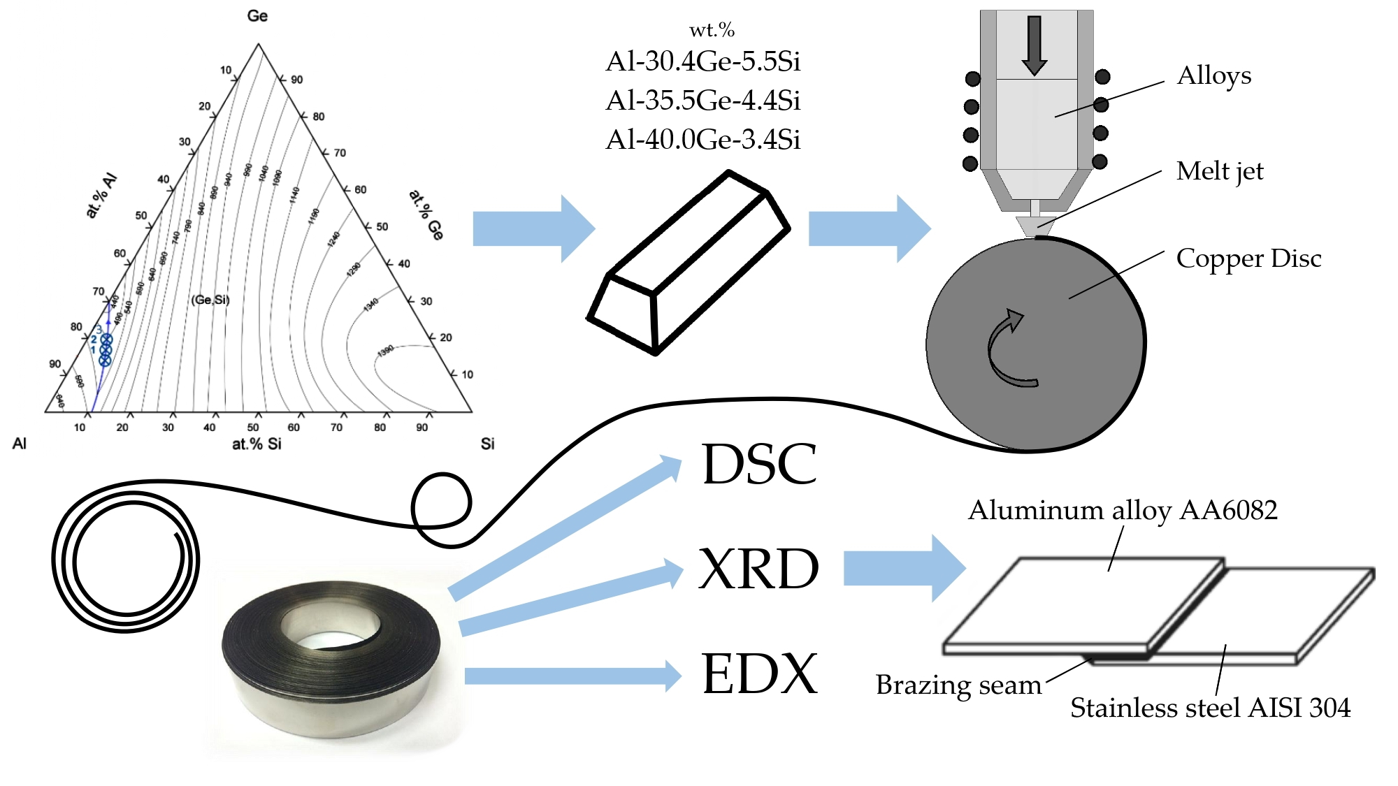
2. Materials and Methods
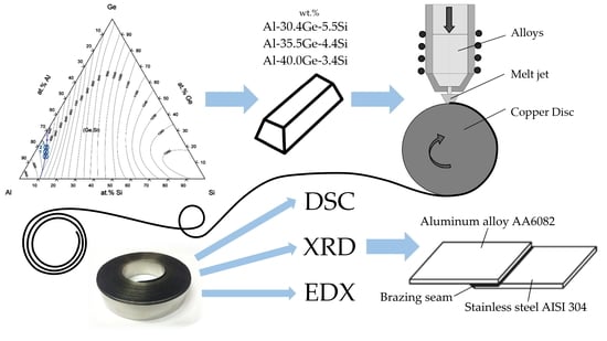
2.1. Materials

Aluminum alloy A0 (GOST 11069), monocrystalline germanium, and silumin were used as the initial alloying materials for the manufacture of the Al-Si-Ge crystal ingots. Ingots of the filler alloys of 200 g for rapid solidification experiments were cast in an induction furnace using a quartz ampoule with argon purge. The production process was carried out as follows. Germanium pieces were added to the melt of aluminum and silicon at the temperature of 700 °C, melted, and held for 15–20 min with continuous stirring by passing an inert gas through the melt. After holding, the molten filler alloys were poured in the air into graphite molds, where their crystallization and subsequent cooling took place. To obtain a homogeneous chemical composition, the ingots were annealed in a resistance furnace SSHVE-1.2,5 (MosZETO, Moscow, Russia) for 5 h at 300 °C in a vacuum of 10−5 mmHg.
In Figure 1, the liquidus surface of the Al-Ge-Si ternary phase diagram is presented. Points 1, 2, and 3 indicate the selected compositions of the filler alloys that theoretically are on the line of the ternary eutectic. The compositions of the filler alloys and theoretical liquidus temperatures are presented in Table 1. Conceivably, the selected alloys will have a eutectic structure. This eutectic will be formed of two phases: the Al-based solid solution, further marked as (Al), and a solid solution of (Ge, Si). However, it should be noted that according to the results of van der Walle [31], at 325 K, the solid solution of (Ge, Si) decomposes into two solid solutions of (Ge, Si)1 and (Ge, Si)2 with the different concentrations of the elements that should be considered when analyzing the results obtained.

2.2. Methods

Differential scanning calorimetry (DSC) was used to determine the solidus and liquidus temperatures of the alloys. The measurements were carried out on the SDTQ600 thermal analyzer (TA Instruments, Lukens, New Castle, DE, USA) in a ceramic crucible in inert gas (helium) atmosphere with a fixed heating and cooling rate of 10 K/min. Heating curves determined solidus temperatures; liquidus temperatures arise as a result of cooling curves.
Microstructures were analyzed using scanning electron microscopy (SEM) with a JEOL JSM-6610LV (Jeol, Tokyo, Japan) and Carl Zeiss EVO 50 XVP (Carl Zeiss, Oberkochen, Germany). Backscattered electron images were also obtained. The elemental composition of the alloys was determined using energy-dispersive X-ray spectroscopy (EDX) using an INCA X-ACT (Oxford Instruments plc., Abingdon, UK). X-ray diffraction (XRD) was performed on a Bruker D8 Discover diffractometer (Bruker, Billerica, MA, USA). The characteristic radiation (Kα) of a copper anode was used. The spectra were decoded using DIFFRAC.EVA software (Bruker, Billerica, MA, USA) and the international radiographic database ICDD PDF-2.
Due to the small size of the microstructural constituents of the braze metal, their properties, especially hardness and indentation modulus, could only be determined at low indentation loads. Therefore, nanoindentation experiments were carried out on the ground and polished cross-sections using a fully calibrated nanoindenter UNAT (Asmec GmbH, Dresden, Germany). The process principle is described in DIN EN ISO 14577-1 [34]. The indentation tests consisted of three steps: loading for 10 s, holding at a maximum force of 20 mN for 5 s, and unloading for 4 s. The indentation experiments were carried out with a Berkovich indenter (ASMEC GmbH, Dresden, Germany). The calibration for the maximum force was carried out on sapphire and quartz. The measurement results were evaluated using a Poisson’s ratio of ν = 0.34 according to the Oliver and Pharr method [35]. To eliminate the influences of the neighboring phases, the positions of all indents were subsequently investigated using SEM. The results of the indents with a distance of less than 4 µm to the phase boundaries were not considered. As a result, at least 30 indents could be used for the evaluation of the hardness and the indentation modulus of each phase.
The Brinell hardness was determined using a TR-2140 hardness tester (NPK Techmash, Neftekamsk, Russia) (GOST 9012-59). The measurements were performed by pressing a steel spherical indenter into the surface of the test sample under various loads for a short period of time. The obtained hardness values were taken directly from the measuring device. The hardness was measured on the surface of the ingot grinds. To clarify the data obtained, at least five measurements were made.

3. Results and Discussion

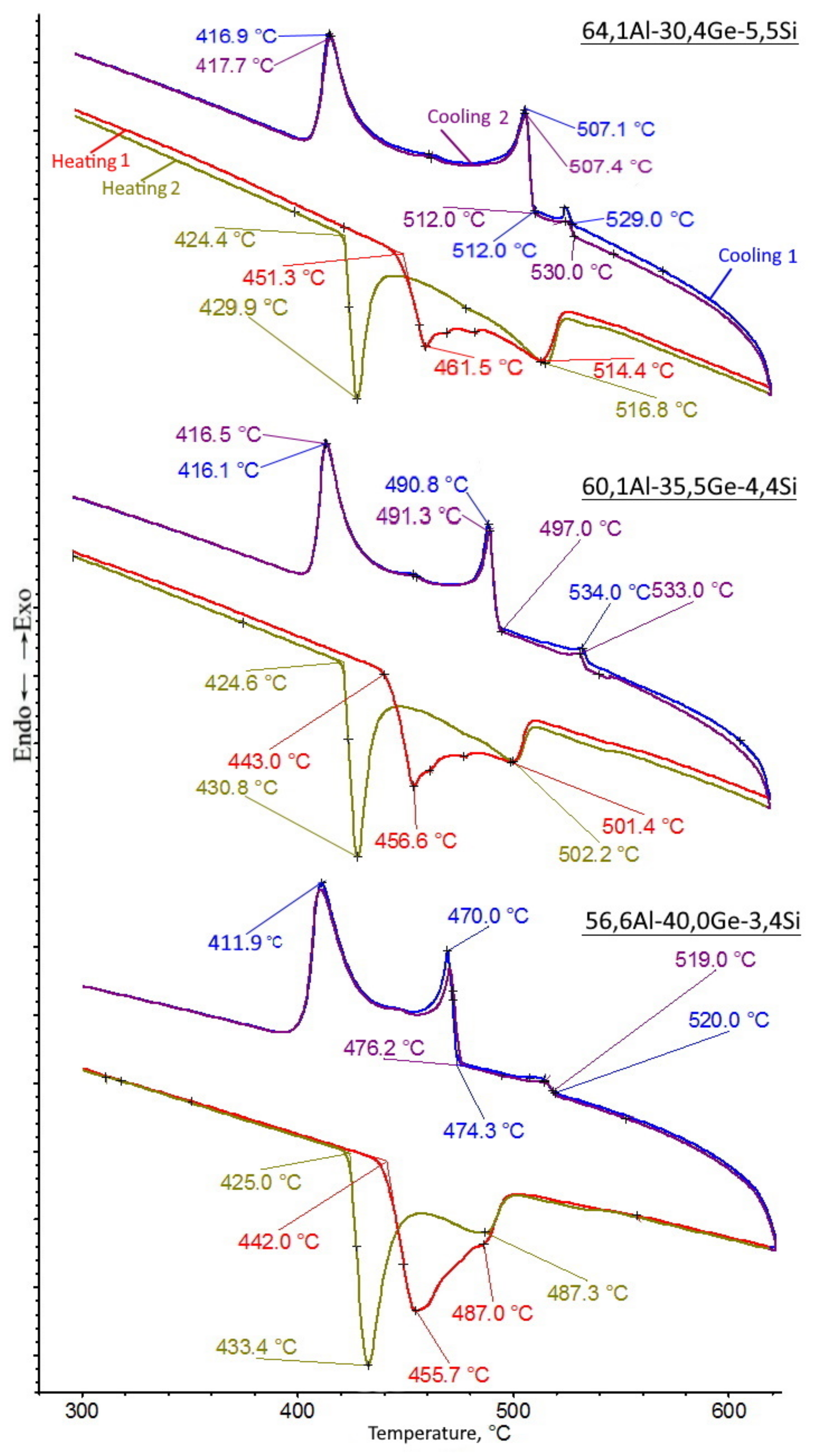
3.1. Melting Characteristics of Filler Alloys

During the study, the foils were heated at a 10 K/min rate, and further melting was carried out. The molten filler alloy was cooled to 60 °C at the same rate (cycle 1). The thermal cycle was then repeated with a drop of the filler alloy formed during equilibrium crystallization (cycle 2). In Figure 2, the DSC curves of the alloys in the foil form are presented.
Moreover, it should be noted that DSС experiments with heating and cooling of the initial ingots were carried out. The obtained curves for the ingots coincide with the curves corresponding to the reheating of the foils (cycle 2). In this regard, the DSC curves of the foils are considered further.
Two endothermic and exothermic peaks were found on the DSC curves during melting and crystallization, which indicate the presence of two structural components. In [21], the formation of a second endothermic peak is noted with an increase in the germanium content from 10 to 20 wt.% when it is added to the classic Al-12Si alloy. This indicates that the formation of the second structural component in Al-Ge-Si alloys occurs at germanium contents of 10 to 20 wt.% and is maintained with a further increase in the content of this element. Upon cooling, crystallization of a certain phase is observed in the DSC curves at 520–533 °C. According to the intensity of heat release, it can be concluded that the content of this phase is insignificant.
The solidus temperature of the ingots did not change with an increase in the germanium content in the alloys and was equal to 424 °C, which corresponds to the melting temperature of the Al-Ge eutectic. The liquidus temperature of the ingots of the filler alloys coincides with the liquidus temperature of the foils. The DSC curves of the foils in comparison with the ingots show a more uniform melting. An increase in the germanium content from 28 to 40 wt.% in the alloys leads to a decrease in the liquidus temperature from 514.8 to 474.3 °C. The experimentally obtained melting temperatures are marginally lower than the theoretical values. After the foils were reheated, the solidus temperature decreased by 17.0 to 29.1 °C, depending on the germanium content. This indicates that the alloys have a lower solidus temperature and a larger melting temperature relative to the foils in the as-cast state. An increase in the germanium content in the filler alloy foils leads to a decrease in the melting temperature range, which should favorably affect the brazing process [36]. The 56.6Al-40.0Ge-3,4Si wt.% alloy had the lowest liquidus temperature and minimum melting temperature range among all the alloys considered, making it the most promising for use as a filler alloy.

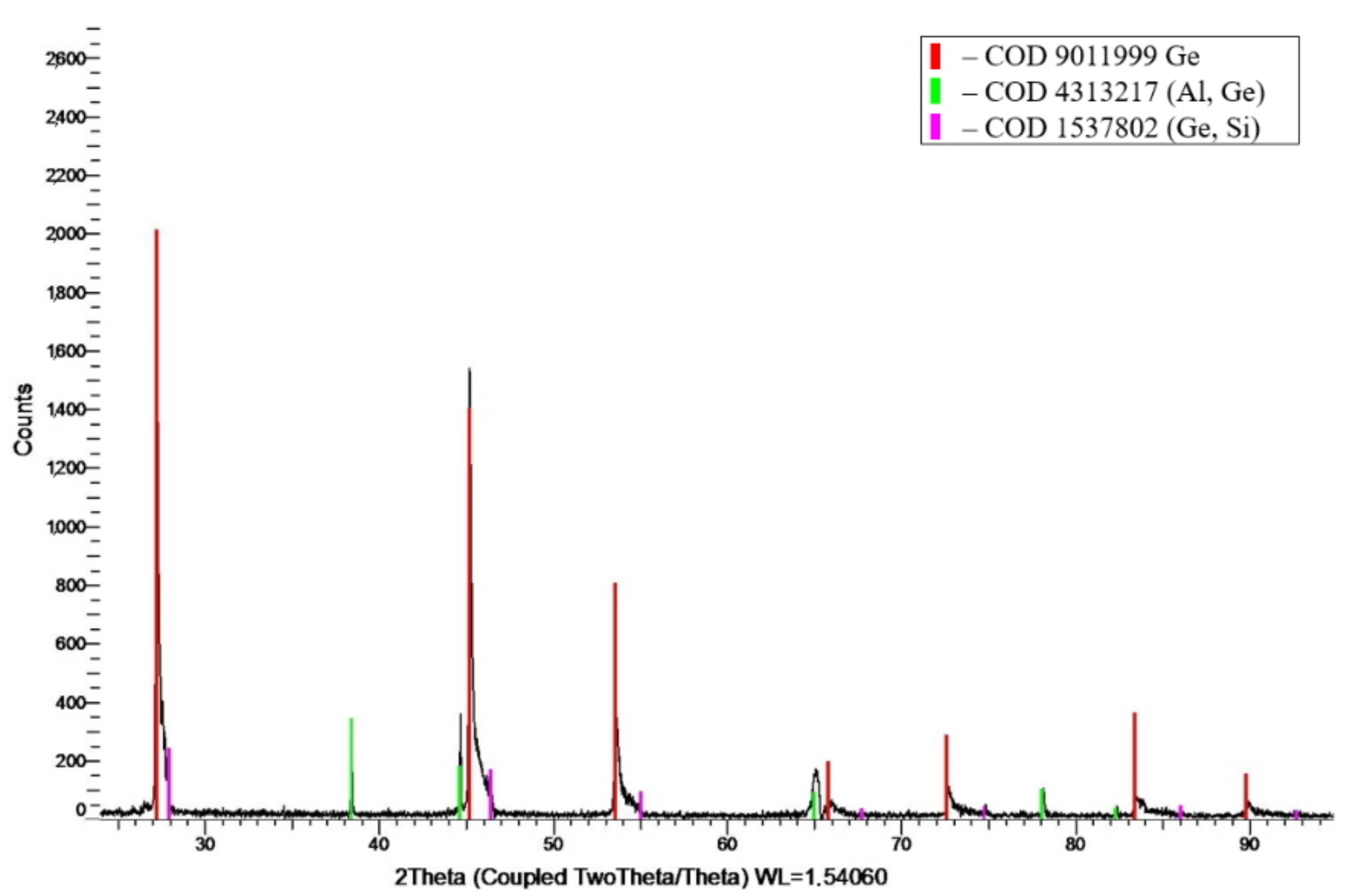
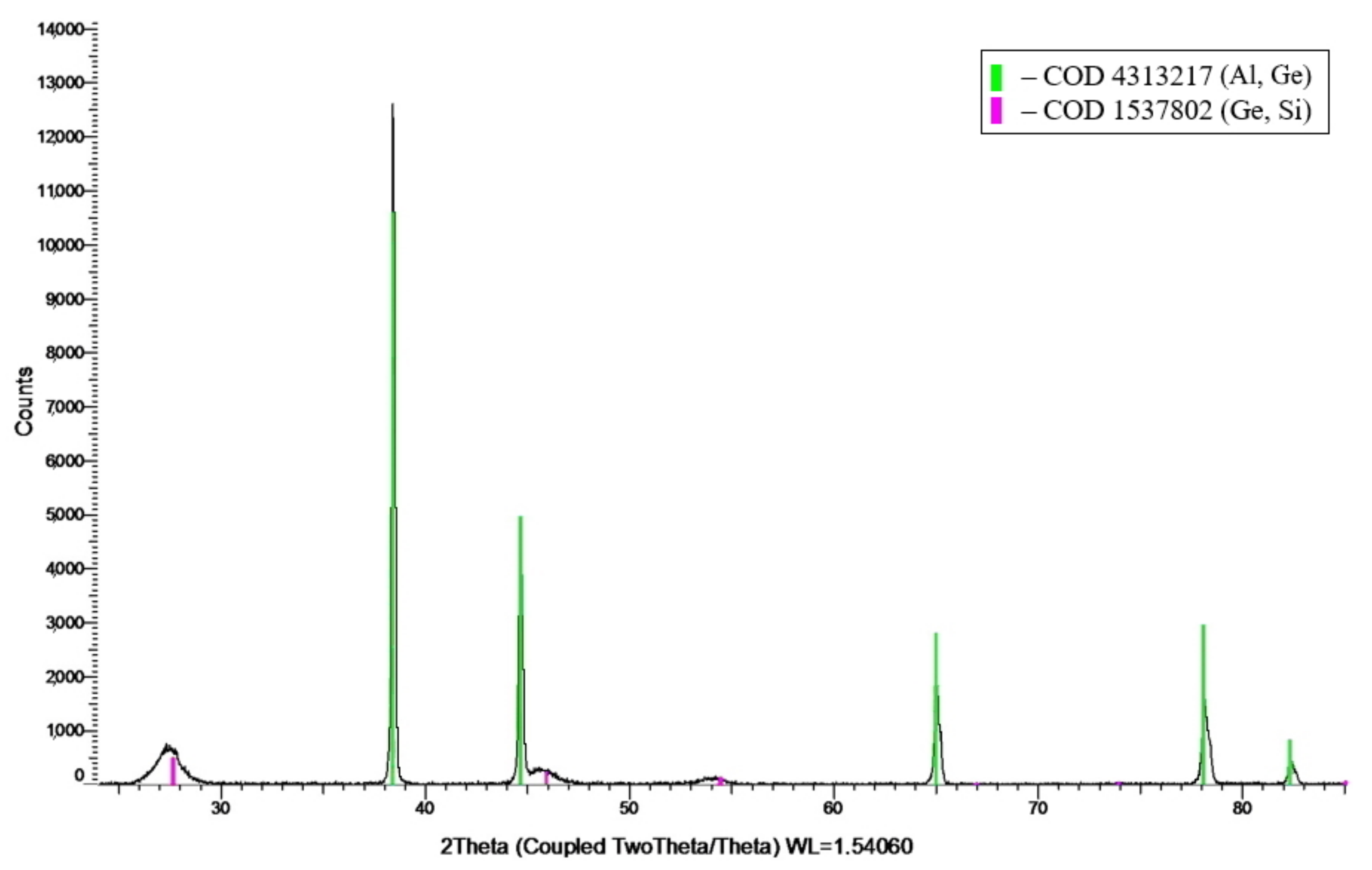
3.2. X-Ray Diffraction Analysis

Figure 3 and Figure 4 show the XRD peaks for the ingot and the foil, respectively, of the 64.1Al-30.4Ge-5.5Si wt.% filler alloy. Table 2 presents the results of the phase analysis.
The XRD results for the ingots showed the presence of three different phases, namely, solid solutions of (Al, Ge) and (Ge, Si) and pure Ge. The solid solution of (Al, Ge) has an FCC lattice with a lattice parameter of a = 4.053 Å. The solid solution of (Ge, Si) has an FCC lattice with a diamond structure with a lattice parameter of 5.601 Å. A broadening of the diffraction peaks for the solid solution of (Ge, Si) is observed on the plot for the foil that may be due to the small size of crystallites. The fluctuation of the chemical composition of this phase causes a small shift of peaks. The phase composition of the foils is more homogeneous, but it differs in the absence of a pure germanium phase. The greater uniformity of the phase composition of the foils is associated with the effect of rapid quenching, due to which metastable solid solutions with an increased germanium content formed. However, due to the formation of two different phases with an ordered arrangement of particles, the structural phase state of the foils is not amorphous.

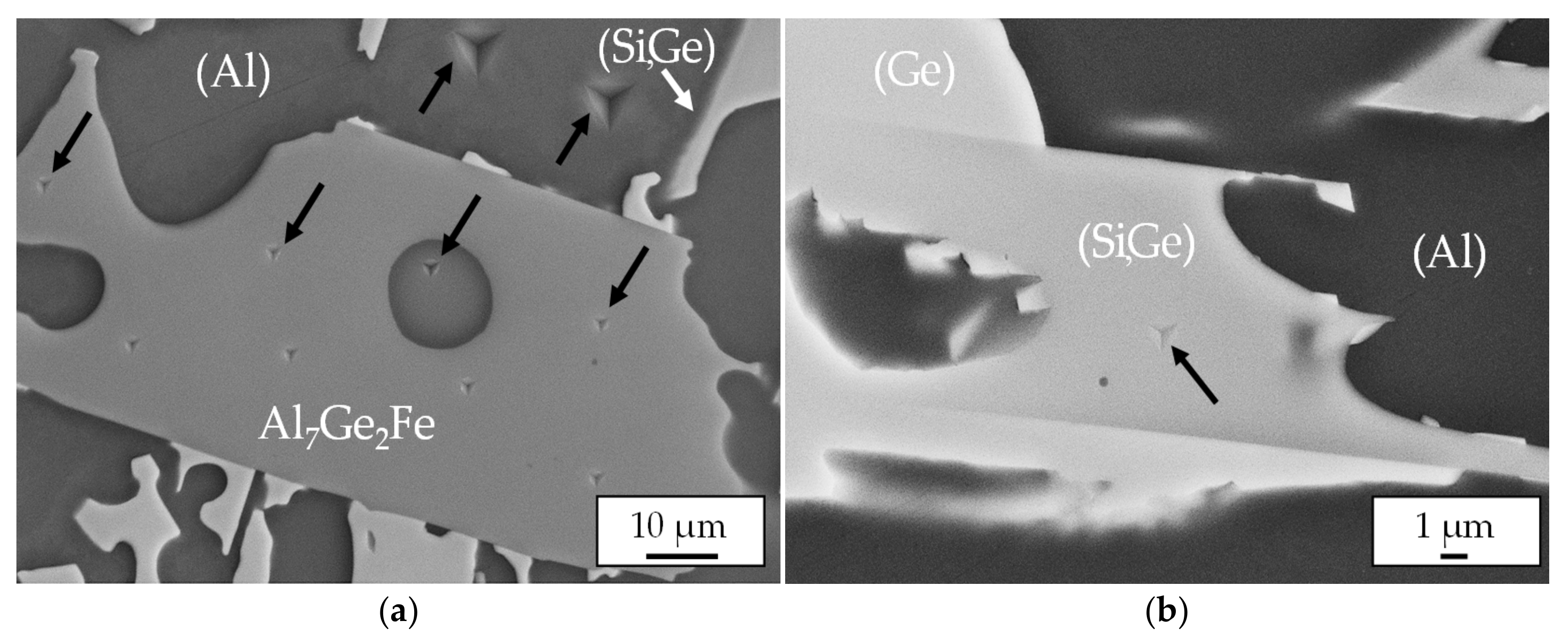
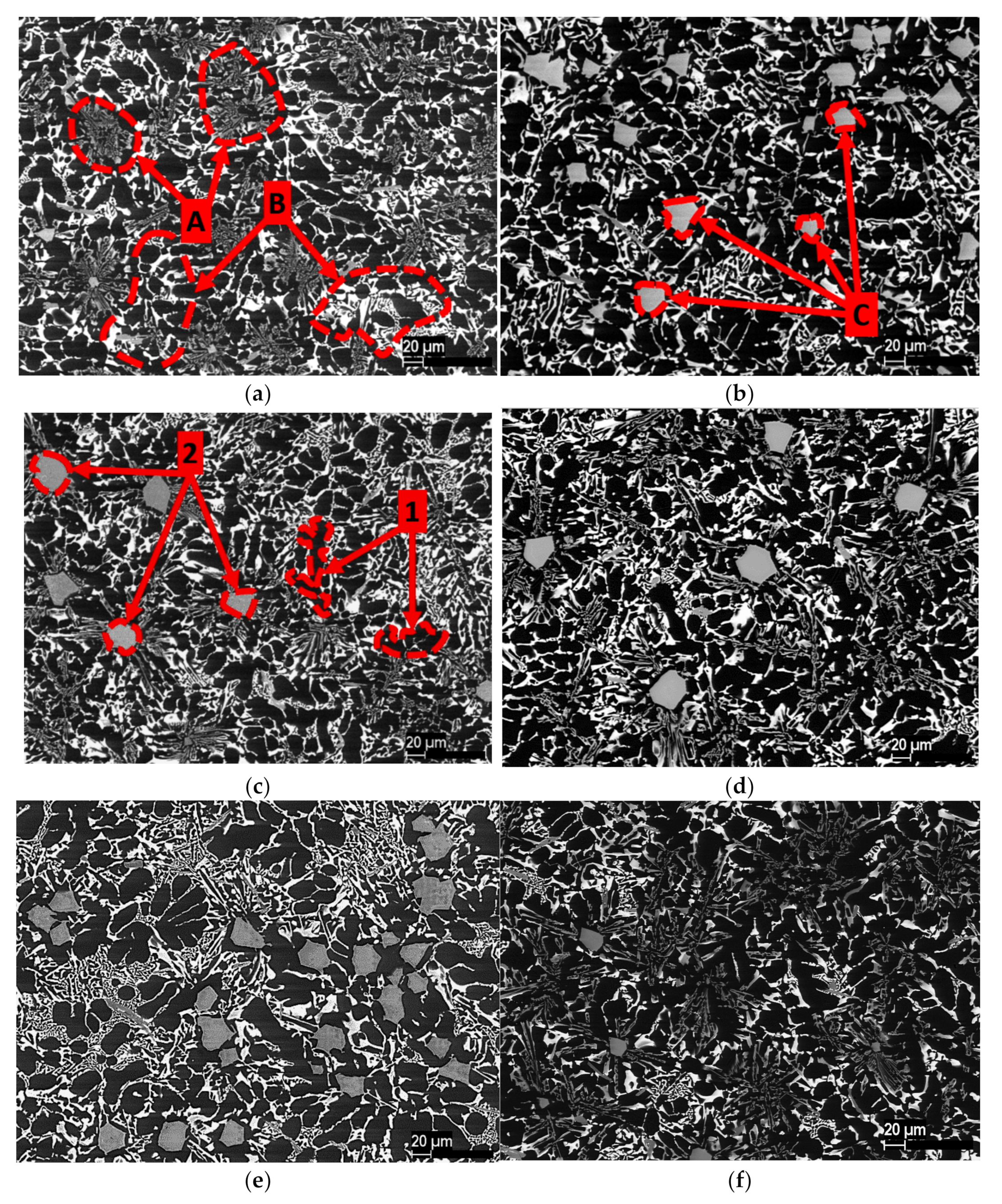
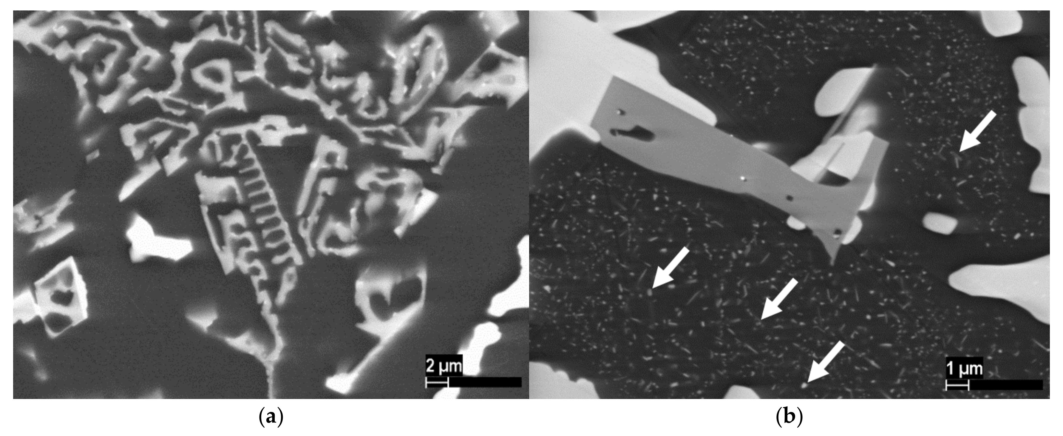
3.3. Microstructures of Al-Ge-Si Filler Alloys

SEM images of the ingots of the Al-Ge-Si system with various compositions and different heat treatments are shown in Figure 5. The study of the microstructures of all samples showed the presence of two morphological types of eutectic, namely, a fine eutectic and a coarse eutectic, which is consistent with the DSC results [23]. The fine eutectic is based on two phases having black and gray colors in the image (area A). The coarse eutectic is based on the phases having black and white colors in the image (area B). Similar structures were obtained in previous works [21,24]. In addition to the eutectics, two different phases in the free state can be distinguished. The first phase is clearly visible on all samples. It is located between the eutectic and in the image with a black color (point 1). The second phase is located at the center of the eutectic structure in the form of clearly faceted particles of a regular shape and the image with a gray color (point 2). This phase was also observed on all samples. However, depending on the state and composition of the alloys, it has different size in Figure 5.
Homogenizing annealing at 300 °C for 5 h led to coagulation of the phase, which has a gray color in the image and is part of the fine eutectic (area A, Figure 5a), into faceted particles of the correct shape (area C, Figure 5b). This is most clearly noticeable during heat treatment of the 64.1Al-30.4Ge-5.5Si alloy ingot.
After annealing, precipitation of the white-colored phase was observed in the black-colored phase (Figure 6b, white arrows), which the aging effect can explain.
SEM images of the microstructures of the foil of the 64.1Al-30.4Ge-5.5Si alloy are shown in Figure 7. The foils of the other filler alloys have similar structures. The side of the foil in contact with the cooling copper disk has a nanocrystalline structure. The grain size of the crystallized filler alloy varies in the range from 10−9 m on the contact side to 10−6 m in the middle of the foil. Moving away from the surface, the grain size increases due to the different cooling rates in the different parts of the foil. The microstructure of the foils is more homogeneous and contains two phases, which is consistent with the results of the XRD and DSC.

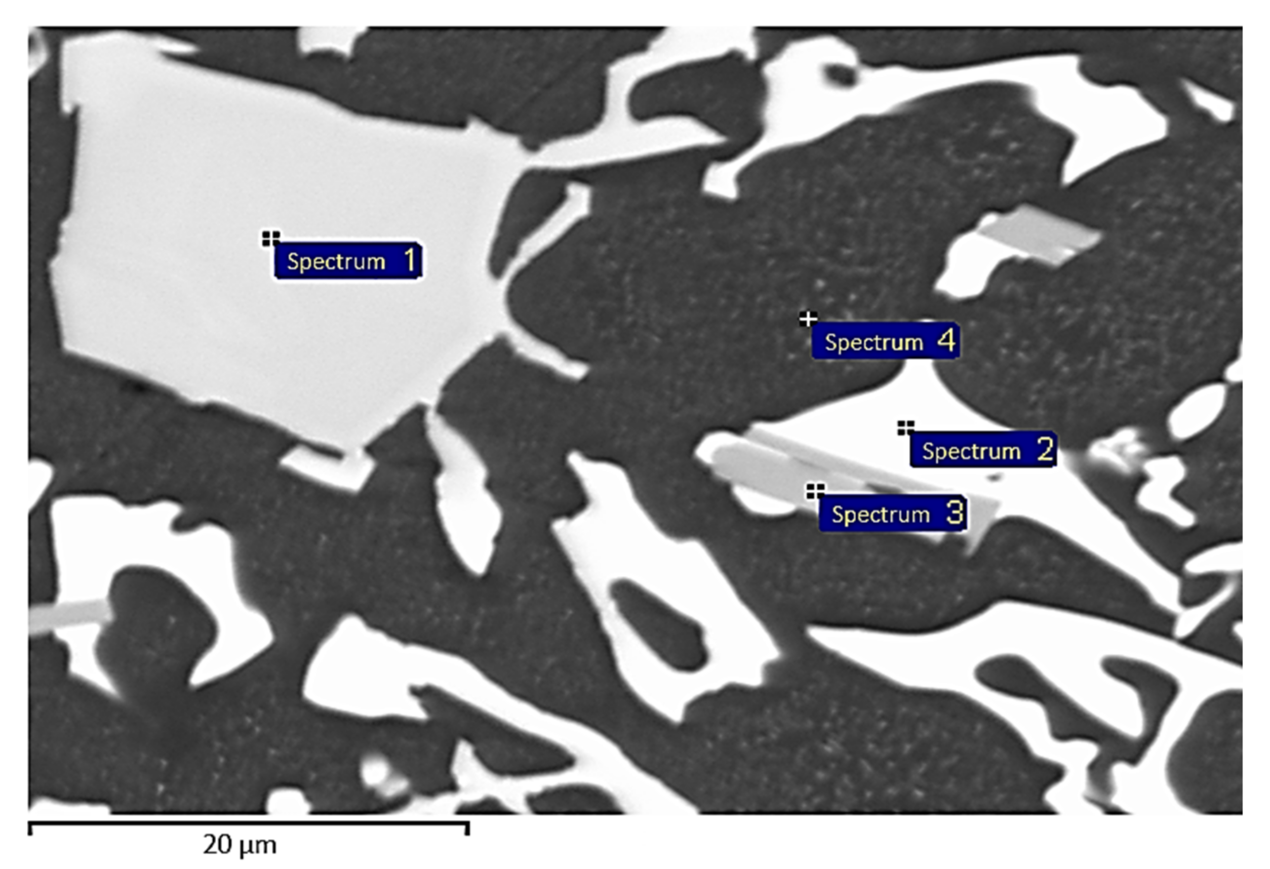
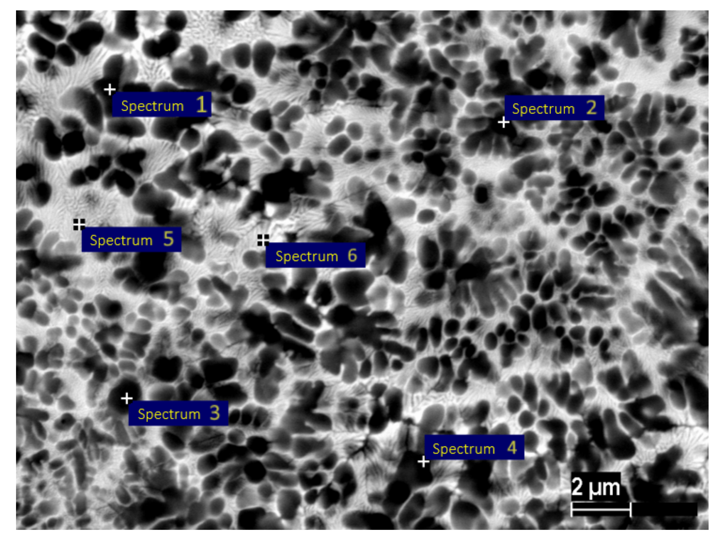
3.4. Energy-Dispersive X-Ray Analysis

EDX was used to further study the Al-Ge-Si ingots and foils (Figure 8, Figure 9 and Figure 10). Table 3, Table 4 and Table 5 show the studied phases’ chemical composition in atomic percentages. The EDX analysis of the phases of the 64.1Al-30.4Ge-5.5Si ingot shows that the phase corresponding to point 5 in Figure 8 is a solid solution of Al with a small Ge content (Table 3). The phase, which has a gray color in Figure 8, consists of solid solutions of (Ge, Si) and (Si, Ge) has a significant liquation of the chemical composition (spectra 1, 4, and 6–8). The phase corresponding to point 2 consists of a solid solution based on Ge with a small content of other elements (Figure 8). A needle-shaped phase corresponding to point 3, which is an intermetallic compound, Al7Ge2Fe, was found. This phase was not detected with XRD due to its small amount. Impurities caused the presence of iron in the alloy in the initial charge material AD0, which contained up to 0.4 wt.% Fe.
After homogenizing annealing at 300 °C for 5 h, the significant liquation in the solid solution of (Si, Ge) was eliminated, as can be seen by the absence of contrast in the phase corresponding to point 1 (Figure 9). The following phases can be distinguished in the ingot structure: Al-based solid solution (spectrum 4); solid solution of (Si, Ge) (spectrum 1); intermetallic Al7Ge2Fe (spectrum 3); Ge-based solid solution (spectrum 2). In the Al-based solid solution, the precipitation of fine particles with a light contrast is observed, presumably consisting of a Ge-based solid solution.
The EDX analysis of the phases of the foil of 64.1Al-30.4Ge-5.5Si shows that the phase with a dark contrast in the image is an Al-based solid solution (spectra 1–4, Table 5). The phase with a light contrast in the image consists of a solid (Al, Ge, Si) solution with a slight fluctuation in chemical composition (Figure 10). The presence of aluminum in the solid solution of (Al, Ge, Si) according to the results of EDX (spectra 5 and 6, Table 5) does not correspond to the results of XRD (Table 2), which show the solid solution of (Ge, Si) and represent a more accurate method of investigation. This may be due to the complexity of analyzing high-dispersive nanocrystalline phases: the measuring device captures adjacent black phases with a high aluminum content. The small size of the phases can also lead to errors associated with the analysis of adjacent phases located under the surface layer.
The EDX analysis results for the ingots were consistent with the results obtained from XRD and DSC. The homogenizing annealing of ingots obtained by casting into a graphite mold made it possible to eliminate the significant liquation of the chemical composition in the solid solution of (Si, Ge).
The main difference between the ingots of different compositions was caused by the change in the volume fraction of the phases in the alloys, while their phase composition remained unchanged. The Al-30.4Ge-5.5Si wt.% alloy in the cast state contains a small amount of (Si, Ge) solid solution particles (Figure 5a). Annealing the alloy that contained 5.5 wt.% Si led to coagulation of the solid solution of (Si, Ge) into faceted particles (Figure 5b). When the Si content was reduced to 3.4 wt.%, the opposite process was observed. The Al-40.0Ge-3.5Si wt.% alloy contains many (Si, Ge) solid solution particles (Figure 5e). Annealing this alloy led to a decrease in the particle size of the solid solution of (Si, Ge), with a redistribution of the solid solution occurring in the volume of the material (Figure 5f). The volume fraction of the solid solution (Si, Ge) and the Ge-based solid solution increase with an increase in the germanium content from 30.4 wt.% to 40.0 wt.%. This was accompanied by a decrease in the volume fraction of the Al-based solid solution (Figure 5).
A similar situation was observed for the results obtained for the foils. The increase in the germanium content in the foils led to the decrease in the volume fraction of the Al-based solid solution and the increase in the volume fraction of the solid solution of (Al, Ge, Si) with high contents of Ge and Si.

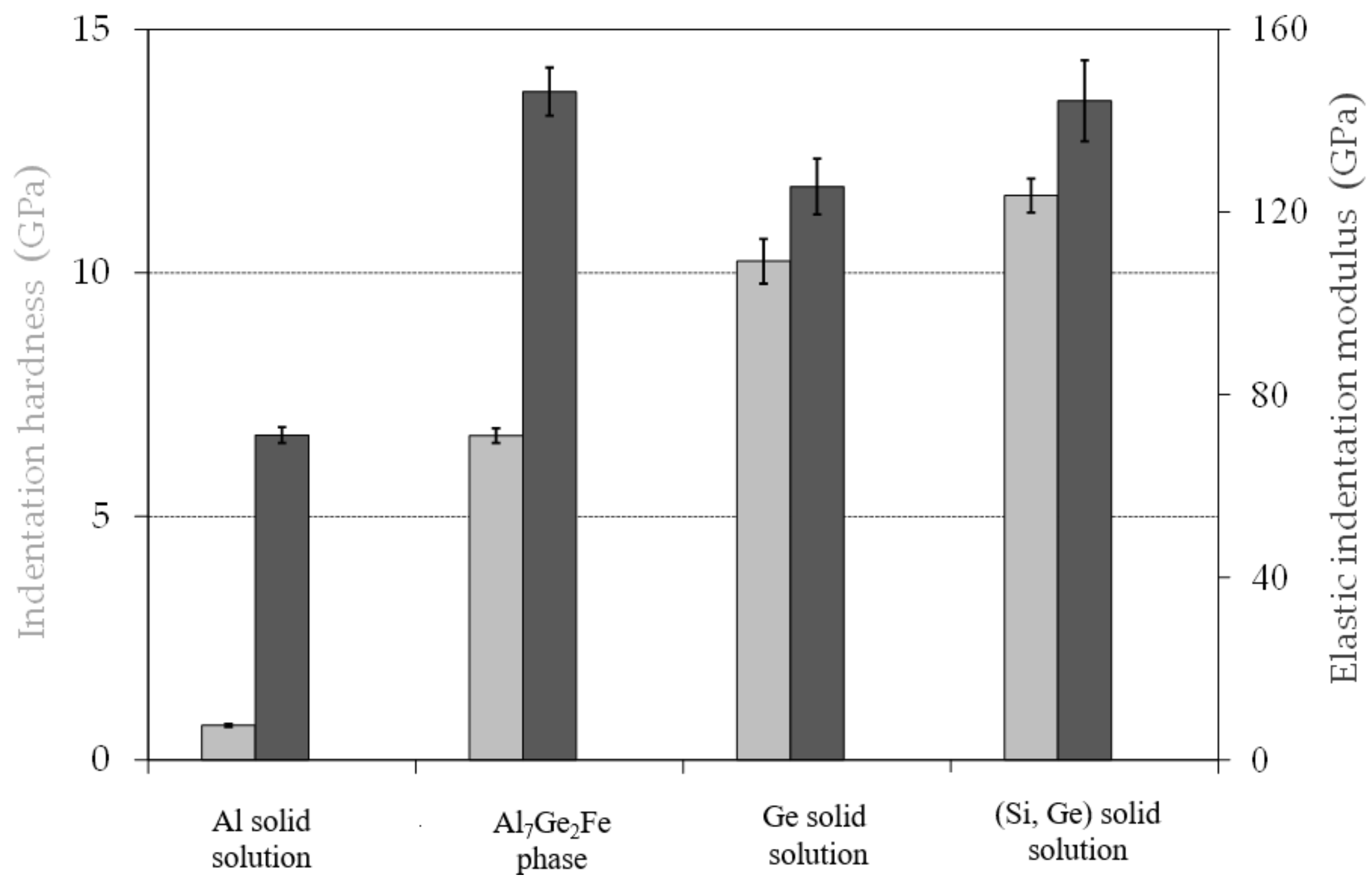
3.5. Mechanical Properties of Filler Alloy

To evaluate the dependence of the mechanical properties on the Ge content, the hardness and nanohardness of the filler alloy ingots of different compositions were measured. Various indents in the Al-Ge-Fe phase Al7Ge2Fe and the Al-based solid solution at different positions are shown in Figure 11a. With regards to the size of the indents, it can be seen that the indents produced in the Al7Ge2Fe intermetallic phase show a lower penetration depth and a smaller contact area compared to the indents made in the Al-based solid solution. The different hardness values of the phases can already be seen in the micrographs. In Figure 11b, an indent in the (Si, Ge) solid solution, used to evaluate the measurements, is presented. This indent shows a good position inside the phase and a sufficient distance to the neighboring phases (Ge- and Al-based solid solutions).
The results of the nanoindentation experiments are summarized in Figure 12. It can be clearly seen that the (Si, Ge) and Ge-based solid solutions are significantly harder than the other microstructural constituents of the braze metal. The hardness of the (Si, Ge) solid solution is 11.6 GPa, while the Al-based solid solution and the Al7Ge2Fe intermetallic phase show hardness values of 0.7 and 6.7 GPa, respectively. In addition, it can be seen that the hardness values of the (Si, Ge) and Ge solid solutions do not differ greatly. The hardness of the Ge-based solid solution is 10.2 GPa. The higher hardness of the (Si, Ge) solid solution compared to the Ge-based solid solution can be explained by the presence of silicon in this phase and the corresponding solid solution hardening. Due to indentation size effects, hardness values in the range of 11.3–12.5 GPa were measured for silicon. For the same reason, the indentation hardness values of germanium are in the range of 8.0–10.5 GPa [37,38]. Consequently, the hardness values measured in the present work correspond to literature data.
Furthermore, the elastic indentation moduli of the investigated microstructural constituents of the braze metal were determined. It can be seen that the elastic indentation modulus of the Al-based solid solution was considerably lower than the measured values of the other microstructural components. The elastic indentation modulus of the Al-based solid solution was 71.2 GPa, while the Al7Ge2Fe intermetallic phase, Ge-based solid solution, and (Si, Ge) solid solution had elastic indentation moduli of 146.4, 125.6, and 144.4 GPa, respectively. The measured values also correspond to literature data for the elastic indentation moduli of these phases [39]. In addition, the comparison of the values of the investigated phases indicates that the Al-based solid solution is easily deformable than the other microstructural components of the braze metal. It was also found that the elastic indentation modulus of the Al-based solid solution is in the range of the elastic moduli of aluminum alloys (60–78 GPa) [40]. This confirms the statement formulated in [34] that the elastic indentation modulus measured by nanoindentation is comparable to the material’s elastic modulus.
The results of the hardness experiments showed that the hardness of the filler alloys is comparable to the hardness of the AA6082 alloy after aging, which is equal to 95 HB [41]. The Al-30.4-5.5 Si wt.% alloy ingot had the highest hardness of 99.8 HB. The rest of the alloys had the same hardness of 83 HB. This allows us to conclude that the mechanical properties of the alloys are close, which is likely to have a positive effect on the mechanical properties of the joints being developed.

4. Conclusions

Nanocrystalline filler alloys of the Al-Ge-Si system with a germanium content of up to 40 wt.% were obtained in the form of a foil using rapid quenching technology. The thickness of the foils equaled 55 ± 1 μm.
Two phase transitions were indicated with DSC. With the germanium content increasing from 28 to 40 wt.%, the melting point of the filler alloys decreased from 514.8 to 474.3 °C, and the melting interval decreased from 62.6 to 32.3 °C. From the perspective of the liquidus temperature and melting interval for brazing high-strength aluminum alloys to stainless steel, the most prospective filler alloy was the Al-40.0Ge-3.4Si wt.% alloy.
Phase analysis showed that the filler foil had a more homogeneous structure than the ingots of the alloys. The foil contained two solid solutions (Al, Ge) and (Ge, Si), while ingots of these alloys also contained pure Ge.
The evaluation of the ingot microstructure showed that the alloy ingots consist of two eutectics: the first consists of a solid solution (Al, Ge) with a solid solution (Si, Ge), the second consists of a solid solution (Al, Ge) with a Ge-based solid solution. With an increase in the germanium content, there was a release of faceted solid solution particles of (Si, Ge) of the correct shape and a further increase in their number. Homogenizing annealing at 300 °C for 5 h led to coagulation of solid solution particles of (Si, Ge) of complex geometry into faceted particles of regular shape. The filler foils had a nanocrystalline structure. The microstructures of the foils were more homogeneous compared to the ingots and contained a eutectic consisting of a solid solution of (Al, Ge) and a solid solution of (Si, Ge), which is consistent with the XRD results.
Nanohardness measurements showed that the (Si, Ge) and the Ge-based solid solutions have similar nanohardness values of 11.6 and 10.2 GPa, respectively. Simultaneously, the Al-based solid solution and the intermetallic Al7Ge2Fe phase have significantly lower nanohardness values of 0.7 and 6.7 GPa. Brinell hardness measurements showed that the filler alloy ingots were sufficiently ductile and had hardness comparable to aluminum base material AA6082 used for brazing with stainless steel AISI 304. The obtained results for the studied ingots and the rapidly-quenched foils can be used to predict the forming structure of the seam after brazing and adjusted for diffusion processes occurring between the brazed materials and the studied filler alloys.

Author Contributions

Conceptualization, O.S. and G.W.; methodology, A.I. and V.F.; software, M.P. and D.B.; validation, D.B., A.I., V.F., and T.U.; formal analysis, A.I., V.F., M.P., and A.A.; investigation, A.I., V.F., M.P., P.M., and A.A.; resources, A.I., V.F., and A.S.; data curation, A.I. and V.F.; writing-original draft preparation, A.A.; writing-review and editing, A.I., V.F., T.U., and D.B.; visualization, A.A. and V.F.; supervision, O.S. and G.W.; project administration, O.S. and G.W.; funding acquisition, A.S., O.S., G.W., A.I., and V.F. All authors have read and agreed to the published version of the manuscript.

Funding

This research was funded by RFBR and DFG, project number 21-52-12026.

Institutional Review Board Statement

Not applicable.

Informed Consent Statement

Not applicable.

Data Availability Statement

Data is contained within the article.

Conflicts of Interest

The authors declare no conflict of interest.

References

  1. Dilthey, U.; Stein, L. Multimaterial car body design: Challenge for welding and joining. Sci. Technol. Weld. Join. 2006, 11, 135–142. [Google Scholar] [CrossRef]
  2. Sierra, G.; Peyre, P.; Beaume, F.D.; Stuart, D.; Fras, G. Steel to aluminium braze welding by laser process with Al–12Si filler wire. Sci. Technol. Weld. Join. 2008, 13, 430–437. [Google Scholar] [CrossRef]
  3. Chang, S.; Tsao, L.; Li, T.; Chuang, T. Joining 6061 aluminum alloy with Al–Si–Cu filler metals. J. Alloy. Compd. 2009, 488, 174–180. [Google Scholar] [CrossRef]
  4. Fedorov, V.; Uhlig, T.; Wagner, G. Influence of the Thickness of the Reaction Zone in Aluminum/Stainless Steel Brazed Joints on the Mechanical Properties. Metals 2021, 11, 217. [Google Scholar] [CrossRef]
  5. Wang, W.-L.; Tsai, Y.-C. Microstructural characterization and mechanical property of active soldering anodized 6061 Al alloy using Sn–3.5Ag–xTi active solders. Mater. Charact. 2012, 68, 42–48. [Google Scholar] [CrossRef]
  6. Miller, W.; Zhuang, L.; Bottema, J.; Wittebrood, A.; De Smet, P.; Haszler, A.; Vieregge, A. Recent development in aluminium alloys for the automotive industry. Mater. Sci. Eng. A 2000, 280, 37–49. [Google Scholar] [CrossRef]
  7. Niu, Z.; Huang, J.; Yang, H.; Chen, S.; Zhao, X. Preparation and Properties of a Novel Al-Si-Ge-Zn Filler Metal for Brazing Aluminum. J. Mater. Eng. Perform. 2015, 24, 2327–2334. [Google Scholar] [CrossRef]
  8. Das, S.K.; Kaufman, J.G. Recycling aluminum aerospace alloys. Adv. Mater. Process. 2008, 166, 34–35. [Google Scholar]
  9. Rajan, R.; Kah, P.; Mvola, B.; Martikainen, J. Trends in Al alloy Development and Their Joining Methods. Rev. Adv. Mater. Sci. 2016, 15, 383–397. [Google Scholar]
  10. Zhou, B.; Liu, B.; Zhang, S. The Advancement of 7XXX Series Aluminum Alloys for Aircraft Structures: A Review. Metals 2021, 11, 718. [Google Scholar] [CrossRef]
  11. Fedorov, V.; Uhlig, T.; Wagner, G. Investigation of fatigue damage in aluminum/stainless steel brazed joints. Weld. World 2018, 62, 609–616. [Google Scholar] [CrossRef]
  12. Simões, S. Diffusion Bonding and Brazing of Advanced Materials. Metals 2018, 8, 959. [Google Scholar] [CrossRef] [Green Version]
  13. Fedorov, V.; Uhlig, T.; Wagner, G. Joining of aluminum and stainless steel using AlSi10 brazing filler: Microstructure and mechanical properties. AIP Conf. Proc. 2017, 1858, 030005. [Google Scholar]
  14. Ouyang, J.-H.; Yarrapareddy, E.; Kovacevic, R. Microstructural evolution in the friction stir welded 6061 aluminum alloy (T6-temper condition) to copper. J. Mater. Process. Technol. 2006, 172, 110–122. [Google Scholar] [CrossRef]
  15. Das, S.K.; Bhattacharya, D.K. Corrosion failure of Zn–Al detonator housing. Eng. Fail. Anal. 2003, 10, 639–643. [Google Scholar] [CrossRef]
  16. Yan, X.; Liu, S.; Long, W.; Huang, J.; Zhang, L.; Chen, Y. The effect of homogenization treatment on microstructure and properties of ZnAl15 solder. Mater. Des. 2013, 45, 440–445. [Google Scholar] [CrossRef]
  17. Dai, W.; Xue, S.; Lou, J.; Wang, S. Microstructure and Properties of 6061 Aluminum Alloy Brazing Joint with Al–Si–Zn Filler Metal. Mater. Trans. 2012, 53, 1638–1643. [Google Scholar] [CrossRef] [Green Version]
  18. Fedorov, V.; Uhlig, T.; Podlesak, H.; Wagner, G. Microstructural Study of Al-Ag-Cu-Si Filler Metal for Brazing High-Strength Aluminum Alloys to Stainless Steel. Metals 2020, 10, 1563. [Google Scholar] [CrossRef]
  19. Velu, P.K. Study of the Effect of Brazing on Mechanical Properties of Aluminum Alloys for Automotive Heat Exchanges. Master’s Thesis, Purdue University, Indianapolis, IN, USA, 2017. [Google Scholar]
  20. Hayes, F.H.; Longbottom, R.D.; Ahmad, E.; Chen, G. On the Al-Si, Al-Ge, and Al-Ge-Si systems and their application to brazing in high power semiconductor devices. J. Phase Equilibria Diffus. 1993, 14, 425–431. [Google Scholar] [CrossRef]
  21. Niu, Z.-W.; Huang, J.-H.; Chen, S.-H.; Zhao, X.-K. Effects of germanium additions on microstructures and properties of Al–Si filler metals for brazing aluminum. Trans. Nonferrous Met. Soc. China 2016, 26, 775–782. [Google Scholar] [CrossRef]
  22. Xu, R.; Zhao, H.; Li, J.; Liu, R.; Wang, W. Microstructures of the eutectic and hypereutectic Al–Ge alloys solidified under different pressures. Mater. Lett. 2006, 60, 783–785. [Google Scholar] [CrossRef]
  23. Stepanov, V.V. Development of Al-Si-Ge System Solders for Increasing the Strength of Brazed Structures Made of Aluminum Alloys. Master’s Thesis, Moscow State Aviation Technological University, Moscow, Russia, 2006. [Google Scholar]
  24. Zhang, Y.; Gao, T.; Liu, X. Influence of Ge content on the microstructure, phase formation and microhardness of hypereutectic Al–Si alloys. J. Alloy. Compd. 2014, 585, 442–447. [Google Scholar] [CrossRef]
  25. Dai, W.; Xue, S.-B.; Lou, J.-Y.; Lou, Y.-B.; Wang, S.-Q. Torch brazing 3003 aluminum alloy with Zn—Al filler metal. Trans. Nonferrous Met. Soc. China 2012, 22, 30–35. [Google Scholar] [CrossRef]
  26. Lyakishev, N.P. State Diagrams of Binary Metallic Systems: A Handbook; Mechanical Engineering: Moscow, Russia, 1996. [Google Scholar]
  27. Schubert, T.; Loser, W.; Teresiak, A.; Mattern, N.; Bauer, H.-D. Preparation and phase transformations of melt-spun Al–Ge–Si brazing foils. J. Mater. Sci. 1997, 32, 2181–2189. [Google Scholar] [CrossRef]
  28. Song, H.; Hellawell, A. Solidification in the system Al-Ge-Si: The phase diagram, coring patterns, eutectic growth, and modification. Met. Mater. Trans. A 1990, 21, 733–740. [Google Scholar] [CrossRef]
  29. Derkachenko, L.I.; Korchunov, B.N.; Nikanorov, S.P.; Osipov, V.N.; Shpeizman, V.V. Structure, microhardness, and strength of a directionally crystallized Al-Ge alloy. Phys. Solid State 2014, 56, 527–530. [Google Scholar] [CrossRef]
  30. Nikanorov, S.; Burenkov, Y.A.; Volkov, M.; Gurin, V.; Derkachenko, L.; Kardashev, B.; Regel, L.; Wilcox, W. Elastic and microplastic properties of Al–Si/Ge alloys obtained from levitated melts. Mater. Sci. Eng. A 2006, 442, 449–453. [Google Scholar] [CrossRef]
  31. van de Walle, A.; Ceder, G. Automating first-principles phase diagram calculations. J. Phase Equilibria Diffus. 2002, 23, 348–359. [Google Scholar] [CrossRef] [Green Version]
  32. Cooper, A.S. Precise lattice constants of germanium, aluminum, gallium arsenide, uranium, sulphur, quartz and sapphire. Acta Crystallogr. 1962, 15, 578–582. [Google Scholar] [CrossRef] [Green Version]
  33. Dismukes, J.P.; Ekstrom, L.; Paff, R.J. Lattice Parameter and Density in Germanium-Silicon Alloys. J. Phys. Chem. 1964, 68, 3021–3027. [Google Scholar] [CrossRef]
  34. ISO 14577-1:2002 Metallic Materials—Instrumented Indentation Test for Hardness and Materials Parameters—Part 1: Test method. 2015. Available online: https://www.iso.org/standard/56626.html (accessed on 2 November 2021).
  35. Oliver, W.C.; Pharr, G.M. An improved technique for determining hardness and elastic modulus using load and displacement sensing indentation experiments. J. Mater. Res. 1992, 7, 1564–1583. [Google Scholar] [CrossRef]
  36. Chuang, T.H.; Yeh, M.S.; Tsao, L.C.; Tsai, T.C.; Wu, C.S. Development of a Low-Melting-Point Filler Metal for Brazing Aluminum Alloys. Metall. Mater. Trans. A. 2000, 31, 2239–2245. [Google Scholar] [CrossRef]
  37. Oliver, J.O. Nanoindentation-Induced Deformation Mechanisms in Germanium. PhD Thesis, The Australian National University, Canberra, Australia, 2008. [Google Scholar]
  38. Kiran, M.S.; Haberl, B.; Bradby, J.E.; Williams, J.S. Nanoindentation of Silicon and Germanium. III-Nitride Electron. Devices 2015, 91, 165–203. [Google Scholar] [CrossRef]
  39. Ge, R.; Hou, X.; Brookshire, K.; Krishnan, N.R.; Silva, D.; Bumgarner, J.; Liu, Y.; Faraone, L.; Martyniuk, M. Nanoindentation of Si1xGex thin films prepared by biased target ion beam deposition. IEEE Xplore 2014, 210–213. [Google Scholar] [CrossRef]
  40. Kammer, C. Aluminium Taschenbuch Band 1: Grundlagen und Werkstoffe; Aluminium-Verlag: Düsseldorf, Germany, 2009. [Google Scholar]
  41. El-Shennawy, M.; Abdel-Aziz, K.; Omar, A.A. Metallurgical and mechanical properties of heat treatable aluminum alloy AA6082 welds. Int. J. Appl. Eng. Res. 2017, 12, 2832–2839. [Google Scholar]
Figure 1. Liquidus surface of Al-Ge-Si ternary phase diagram [32,33].
Metals 11 01926 g001
Figure 2. DSC curves for the foil of the Al-Si-Ge filler alloys (wt.%).
Metals 11 01926 g002
Figure 3. XRD peaks for the ingot of the 64.1Al-30.4Ge-5.5Si (wt.%) filler alloy.
Metals 11 01926 g003
Figure 4. XRD peaks for the foil of the 64.1Al-30.4Ge-5.5Si (wt.%) filler alloy.
Metals 11 01926 g004
Figure 5. Microstructures of alloy ingots with various heat treatments obtained by SEM at 250× magnification: (a) Al-30.4Ge-5.5Si wt.% in cast condition; (b) Al-30.4Ge-5.5Si wt.% annealed according to the 300 °C/5 h mode; (c) Al-35.5Ge-4.4Si wt.% in cast condition; (d) Al-35.5Ge-4.4Si wt.% annealed according to the 300 °C/5 h mode; (e) Al-40.0Ge-3.4Si wt.% in cast condition; (f) Al-40.0Ge-3.4Si wt.% annealed according to the 300 °C/5 h mode.
Metals 11 01926 g005
Figure 6. Microstructures of ingots of 64.1Al-30.4Ge-5.5Si wt.% alloy with various heat treatments obtained by SEM: (a) cast alloy at 2500× magnification; (b) ingot annealed according to the 300 °C/5 h mode at 5000× magnification.
Metals 11 01926 g006
Figure 7. Microstructures of 64.1Al-30.4Ge-5.5Si (wt.%) alloy foil obtained by SEM.
Metals 11 01926 g007
Figure 8. SEM image of alloy ingot 64.1Al-30.4Ge-5.5Si with the EDX measurement points.
Metals 11 01926 g008
Figure 9. SEM image of alloy ingot 64.1Al-30.4Ge-5.5Si after annealing at 300 °C, 5 h mode with the EDX measurement points.
Metals 11 01926 g009
Figure 10. SEM image of the foil of alloy 64.1Al-30.4Ge-5.5Si with the EDX measurement points.
Metals 11 01926 g010
Figure 11. SEM images of: (a) various indents in the Al-Ge-Fe phase and Al-based solid solution and (b) an indent in the (Si, Ge) solid solution.
Metals 11 01926 g011
Figure 12. Indentation hardness (light) and elastic indentation modulus (dark) of the microstructural constituents of the braze metal.
Metals 11 01926 g012
Table 1. Chemical compositions of filler alloys.
No.AlloyAlloy Composition (at.%)TL (°C)
AlSiGe
1Al-30.4Ge-5.5Si79.36.714.0520
2Al-35.5Ge-4.4Si77.45.617.0505
3Al-40.0Ge-3.4Si75.84.319.9490
TL: predicted liquidus temperature
Table 2. XRD analysis results.
SamplePhase CompositionCrystal Lattice Parameters
64.1Al-30.4Ge-5.5Si
foil
Solid solution of (Al, Ge)FCC (Fm-3m), а = 4.0519 Å, d = 243 nm
Solid solution of (Ge, Si)FCC diamond (Fd-3m), а = 5.6006 Å, d = 18 nm
64.1Al-30.4Ge-5.5Si
ingot
Solid solution of (Al, Ge)FCC (Fm-3m), а = 4.0546 Å, d = 461 nm
Pure GeFCC diamond (Fd-3m), а = 5.6628 Å, d = 82 nm
Solid solution of (Ge, Si)FCC diamond (Fd-3m), а = 5.6073 Å, d = 29 nm
Table 3. Results of the EDX analysis of 64.1Al-30.4Ge-5.5Si alloy ingot.
Measurement PointChemical Composition (at.%)Phase
Interpretation
AlSiFeGe
Spectrum 12.015.21.281.6(Ge, Si)1
Spectrum 23.92.40.093.7(Ge)
Spectrum 368.82.510.817.9Al7Ge2Fe
Spectra 4, 6 and 81.356.80.042.9(Si, Ge)
Spectrum 598.40.20.01.4(Al)
Spectrum 71.732.30.066.0(Ge, Si)2
Table 4. Results of the EDX analysis of 64.1Al-30.4Ge-5.5Si alloy ingot after annealing at 300 °C for 5 h.
Measurement PointChemical Composition (at.%)Phase
Interpretation
AlSiFeGe
Spectrum 11.853.60.044.6(Si, Ge)
Spectrum 22.95.00.092.1(Ge)
Spectrum 364.02.39.024.7Al7Ge2Fe
Spectrum 498.70.20.01.1(Al)
Table 5. Results of the EDX analysis of 64.1Al-30.4Ge-5.5Si alloy foil.
Measurement PointChemical Composition (at.%)Phase
Interpretation
AlSiGe
Spectra 1–494.42.33.3(Al)
Spectra 5 and 660.413.426.2(Al, Ge, Si)
Publisher’s Note: MDPI stays neutral with regard to jurisdictional claims in published maps and institutional affiliations.

