Article

Enhancement of the Mechanical and Tribological Properties of Aluminum-Based Alloys Fabricated by SPS and Alloyed with Mo and Cr

by
Sergey N. Grigoriev
1,
Alexander Mironov
1,2,
Ekaterina Kuznetsova
1,
Yuri Pristinskiy
1,
Pavel Podrabinnik
1,
Nestor Washington Solís Pinargote
1,
Iosif Gershman
1,2,
Pavel Peretyagin
1 and
Anton Smirnov
1,*
1
Department of High-Efficiency Processing Technologies, Moscow State University of Technology “STANKIN”, Vadkovsky per. 1, Moscow 127055, Russia
2
Department of Scientific Research Programs, Grants and Projects, Railway Research Institute JSC “VNIIZHT”, 3rd Mytischinskaya Street 10, Moscow 107996, Russia
*
Author to whom correspondence should be addressed.
Metals 2021, 11(12), 1900; https://doi.org/10.3390/met11121900
Submission received: 12 October 2021 / Revised: 18 November 2021 / Accepted: 24 November 2021 / Published: 25 November 2021

Abstract

:
Multicomponent aluminum-based alloys doped with chromium (Cr) and molybdenum (Mo), fabricated by spark plasma sintering (SPS), derived from a powder mixture prepared by mechanical alloying, were studied in this work. The morphology of the pristine and worn surfaces was analyzed using a scanning electron microscope equipped with an energy-dispersive X-ray spectroscopy system. The obtained alloys exhibited higher hardness (73 and 72) for the Al–Mo and Al–Cr alloys, respectively, compared to reference bronze. Besides improved hardness, SPS-sintered alloys also showed a lower value of the weight and linear wear and the highest score-resistance compared to bronze. The enhanced tribological behavior is related to the formation of secondary structures on the friction surfaces of rubbing pairs, which in turn reduce wear. For the first time, the present research has demonstrated the effectiveness of the addition of Mo and Cr for the fabrication of sintered multicomponent Al-based alloys with a tailored microstructure that induces the formation of secondary structures on the tribosurfaces due to the self-organization processes during friction.

1. Introduction

Today, most monometallic plain bearings are produced by casting bronze alloys to meet demanded mechanical and tribological properties. However, for bronze bearings, a significant disadvantage is the Rebinder effect in an emergency, where molten copper droplets become a surface-active substance for steel, causing the appearance of cracks at the boundaries of steel grains up to the complete fracture of the steel counter body. Therefore, research on the development of new antifriction aluminum alloys that can replace bronze in the manufacture of monometallic plain bearings is relevant. Moreover, replacing bronze with aluminum alloy gives a noticeable economic effect since aluminum is 2.5 times cheaper than copper in terms of unit weight cost and 3.3 times lighter.
Monometallic bearings are usually produced by casting. In this regard, the alloys used in their manufacturing should have favorable casting properties: high fluidity, low tendency to form shrinkage porosity, and cracking. Therefore, silicon (Si) is the main alloying element of aluminum casting alloys as it provides all these qualities [1,2,3,4].
Various bearings require different combinations of the service characteristics of antifriction materials, which results in the necessity for fabrication of a whole range of aluminum alloys with different running-in ability, scuff, and wear resistance as well as to minimize wear of the steel counter body. To extend the service life of bearings and provide their resistance to wear different technological methods are used. The coating is one of the most common processes. So far, different materials and products have been developed and investigated for these purposes. The possibility of production of multilayer coatings in a titanium-nitride/chrome-nitride system with high hardness (up to 57 GPa) was reported by Sobol et al. [5]. Another work showed that the developed coating composition based on Ti–TiN–TiAlCrN drastically improved the operational life of the cutting inserts (more than double) [6]. Ren et al. demonstrated that diamond-like carbon (DLC) coatings could be considered as promising surface coatings of engine parts in terms of friction and wear performance [7]. Summer et al. reported that various polymer-coated bearings tested provide enhanced friction and wear performance in comparison to other bearing types (e.g., lead-based electroplated) [8]. The production of complex-shaped dielectric products of superhard and tough nanocomposite coatings with wide interfaces, which were developed with a combined source of metal atoms and pulsed beams of fast neutral molecules with the energy of 50–200 eV, was described in [9]. The formation and microstructure of the Ti–TiN–(Ti, Al, Si)N coating were investigated. It was found that the (Ti, Al, Si)N nanolayer structure of the coating made it possible to restrain the growth of grains within the nanometric range [10,11,12]. However, despite their diversity and variety of deposition techniques, coatings alone cannot be always effective in both sliding performance and wear resistance characteristics of materials (bearings, cutting tools, engines, automotive brakes) especially when working in boundary and mixed friction lubrication conditions (start-stop cycles) under high load applications. In addition, plain bearings are usually designed to have loading capacity to withstand heavy weight from the shaft. Thus, in order to perform both the antifriction and load-bearing functions, a certain set of mechanical and tribological properties of the alloys from which the bearing materials are made is required. To balance colliding properties, new alloys are being developed by adding different elements responsible for mechanical and tribological performance. Magnesium, zinc, and nickel are used as major alloying elements in the vast majority of Al–Sn–Cu antifriction alloys. Copper [13,14] is added to aluminum alloys to strengthen them. The strengthening maximum is between 4% and 6% Cu, depending upon the influence of other constituents present. The mechanical alloying of Mg to Al–Sn alloys was reported to increase strength and wear performance by improving the distribution of Sn. Lu et al. found that the appropriate addition of Mg could increase wettability and improve the distribution of Sn phase, strength, and ductility of the alloy [15]. The addition of zinc to aluminum (in conjunction with some other elements, primarily magnesium and/or copper) produces heat-treatable aluminum alloys with enhanced strength. Zinc substantially increases strength and allows precipitation hardening. Low melting zinc phases show chemical activity that contributes to the formation of protective secondary structures on the rubbing surface, and increases the running-in ability and wear resistance [16,17]. Nickel is added to aluminum–copper and aluminum–silicon alloys to improve hardness and strength at elevated temperatures and to reduce the coefficient of thermal expansion [18,19]. Tin [20,21,22,23] and lead [24,25,26,27] are present as soft structural components in these alloys that act as solid lubricants. Therefore, to achieve high values of both mechanical and tribological properties, the composition of Al-based alloys can include many alloying elements and form different intermetallic phases such as CuAl2, Al3Ni, Al3Ni2, Al7Cu4Ni, Al9FeNi, AlFeMnSi, and Al5Cu2Mg8Si6, etc. The addition of chromium (Сr) and molybdenum (Mo) improves the strength and wear resistance of the alloys. Nasef et al. reported that Al-based alloys with 10 wt.% of Cr showed higher wear resistance and improved mechanical properties than compositions without chrome [28]. The tensile and aging properties of the Al–Si–Cu–Mg alloy modified with additions of Cr, Ti, V, and Zr were examined by Shaha et al. [29]. It was shown that the modified alloy formed the different dispersoid phases with a variety of morphologies that enhance the strength of the alloys at elevated temperatures. The presence of Mo enhances the strength properties of the Al-based alloys [30,31]. In addition, molybdenum interacts with sulfur (S), which is usually part of the chemical compositions of lubricant and forms molybdenum sulfide (MoS2), which in turn could significantly improve the tribological performance of friction surfaces [32,33]. Due to the synergistic interaction of all the constituent alloying elements with each other and with the aluminum matrix, special friction layers (tribofilms) are formed on friction surfaces referred to as “secondary structures” by the authors of the present work.
Processes of friction and wear are realized on a background of the raised gradient relations of temperature, stresses, the concentration of alloying elements, and defects of a crystal structure and represent a complex set of physical and chemical phenomena as a consequence of what the self-organization processes appear on the friction surface in tribopairs [34,35]. The essence of this phenomenon is that under the influence of an external perturbation any thermodynamically open nonlinear system is rearranged in such a way that its response maximally compensates for the internal cause that caused such an internal change [36,37]. The following processes are manifestations of self-organization in friction: formation of secondary structures with a different, in the limit higher strength and wear resistance in comparison to the initial one; development of equilibrium roughness irrespective of the initial microgeometry of friction surfaces; increase in the actual contact area due to linear wear and, as a consequence, decrease in contact loads; realization of selective transfer, etc. The external form of self-organization is the reduction and stabilization of practically all energy, force, and tribotechnical parameters of friction and wear process, in particular friction coefficient, temperature, wear rate, etc. The enforcement addition of appropriate chemical elements to the tribosystem assists in the formation of necessary secondary structures. Studies on the role of chemical elements in secondary structures have been carried out [38,39]. The studies showed an example of optimization of magnesium content in antifriction material in terms of ensuring its presence in secondary structures to reduce wear rate [40,41]. In addition, it was reported that chromium and molybdenum), which are part of the steel, were detected in secondary structures on the friction surfaces of aluminum-based alloy [39]. The presence of these elements accelerates the processes of self-organization and adaptation on the rubbing surface. Therefore, the improved mechanical and wear properties of multicomponent aluminum alloys can be achieved by adding low-melting and refractory elements. However, it should be pointed out that traditional metallurgical methods make it practically impossible to simultaneously alloy aluminum with both refractories (chromium and molybdenum) and low-melting metals (tin, lead, zinc). The former is distributed unevenly, while the latter burn out at high temperatures. Therefore, alternative manufacturing methods are needed.
Mechanical alloying (MA) technology is an effective way to create forced miscibility in immiscible systems with controllable microstructure, which cannot be obtained by other means. Through this technology, it is possible to influence the different phases formed in an alloy by changing the composition of the initial powders and their milling technology [42,43,44,45].
In addition, the oxide film continuity on the aluminum particles is broken during this process. The oxide-free surfaces easily interact with each other, which further increases the strength of the sintered material. The separated oxide film particles, which have higher hardness and wear resistance compared to the aluminum matrix, form fairly evenly distributed conglomerates within the alloy. As a result, there is an additional resource for improving tribotechnical properties-alloy becomes more consistent with the first rule of Charpy, according to which the antifriction material should consist of hard, evenly distributed strong inclusions and softer and more ductile matrix.
Then for the fabrication of bulk samples derived from mixtures prepared by mechanical alloying spark plasma sintering (SPS) technique was used. This consolidation method offers considerable advantages such as faster and shorter processing time compared to conventional sintering methods, due to simultaneous application of mechanical pressure and electric pulse. The advantages of this technique are associated with a high densification rate and fine microstructure and consequently better properties [46,47,48,49]. Moreover, SPS allows the breaking of the continuity of oxide film on the surface of aluminum particles. In our previous study, we had confirmed the effectiveness of the MA and spark plasma sintering method for the preparation of tailored mixtures of metallic powders, enabling microstructural characteristics that could be favorable for the formation of secondary structures on the tribosurfaces [48]. However, the evaluation of the mechanical and tribological behavior of the obtained compositions was not presented.
The present investigation aims to analyze the impact of Cr and Mo on mechanical properties of SPS-ed multicomponent aluminum alloys derived from powders synthesized by MA technology, evaluate the effect of the presence of these elements on the formation of favorable secondary structures on the friction surfaces, and tribological behavior of shaft-plain bearing couple. To facilitate their reach into secondary structures these elements were added to the raw powder mixture. Of particular interest are the studies on microstructure, mechanical properties, and tribological behavior of SPS-ed multicomponent aluminum alloys.
2. Materials and Methods

2.1. Compositions Processing

Table 1 shows the nominal chemical compositions of studied alloys. The studied alloys were labeled Al–X where the X demonstrates the presence of Mo or Cr in composition.
Pure metal powders (Table 2) were mechanically alloyed in a high-energy mill using isopropanol as liquid media to avoid powers oxidation. First of all, two different mixes, Sn + Mg + Pb and Al + Si + X were mixed separately for 48 and 24 h, respectively. Then obtained mixes were combined into one and copper and zinc powders were added to the mixture. The resultant mixture was homogenized for 12 h. It should be clarified that hard metal balls were used for homogenization and each mixture was dried, grounded in an agate mortar, and passed through a 63 µm sieve. More detailed information concerning the mixing process was provided in the previous study [48].
Obtained suspensions were dried using a vacuum drying oven and sieved through a 63 µm mesh.

2.2. Hybrid Spark Plasma Sintering (HSPS)

Afterward, obtained mixtures were placed in a die-punch setup made from isostatic graphite (grade C4, DonCarb Graphite, Rostov, Russia) and dense samples were produced by H HP D-25 SD hybrid spark plasma sintering (FCT Systeme GmbH, Rauenstein, Germany). In contrast to conventional SPS, the hybrid technique requires additional resistance or induction heating thus avoiding temperature gradients in the case of materials manufacturing with larger size or diameter [50].
Sintering was performed in a vacuum and a constant pressure of 50 MPa was applied from the beginning of the heating step to the end of the dwell. For all the sintering experiments, the heating from room temperature to 500 °C was controlled by a preset heating program and completed within 10 min, at a heating rate of 50 °C/min. The final temperature and pressure were maintained for 5 min. The temperature was controlled during sintering by a pyrometer situated at the top of the machine and focused at the center of the blank (3 mm over the top surface). As-sintered discs of 80 mm diameter of approximately 15 mm in height were produced.

2.3. Microstructural Characterization

A scanning electron microscope (SEM) VEGA 3 (Tescan, Brno, Czech Republic) was used for the characterization of surfaces polished down to 1 µm. The energy-dispersive X-ray spectroscopy (EDS) spectra were conducted in specific regions at 20 kV voltage and 12 µA beam current for 5 min to obtain well-resolved peaks for the chemical microanalysis of sintered samples. Bulk densities of the sintered specimens were determined by using the Archimedes method in water.

2.4. Mechanical Properties Measurement

To determine maximum tensile strength (σ, МPa) a total of 10 cylindrical sample pieces with length 55 mm and diameter of 5 mm were turned out from sintered discs. The tests were performed at room temperature using electromechanical universal testing machine Instron 5989 (INSTRON Company, Norwood, MA, USA).
The hardness of the polished down to 2.5 µm (4000 Grit) samples was determined by the Brinell hardness test using Wilson Hardness BH 3000 (Buehler, Lake Bluff, IL, USA) with a steel ball d = 2.5 mm and an applied load of 156 N.

2.5. Tribological Behaviour

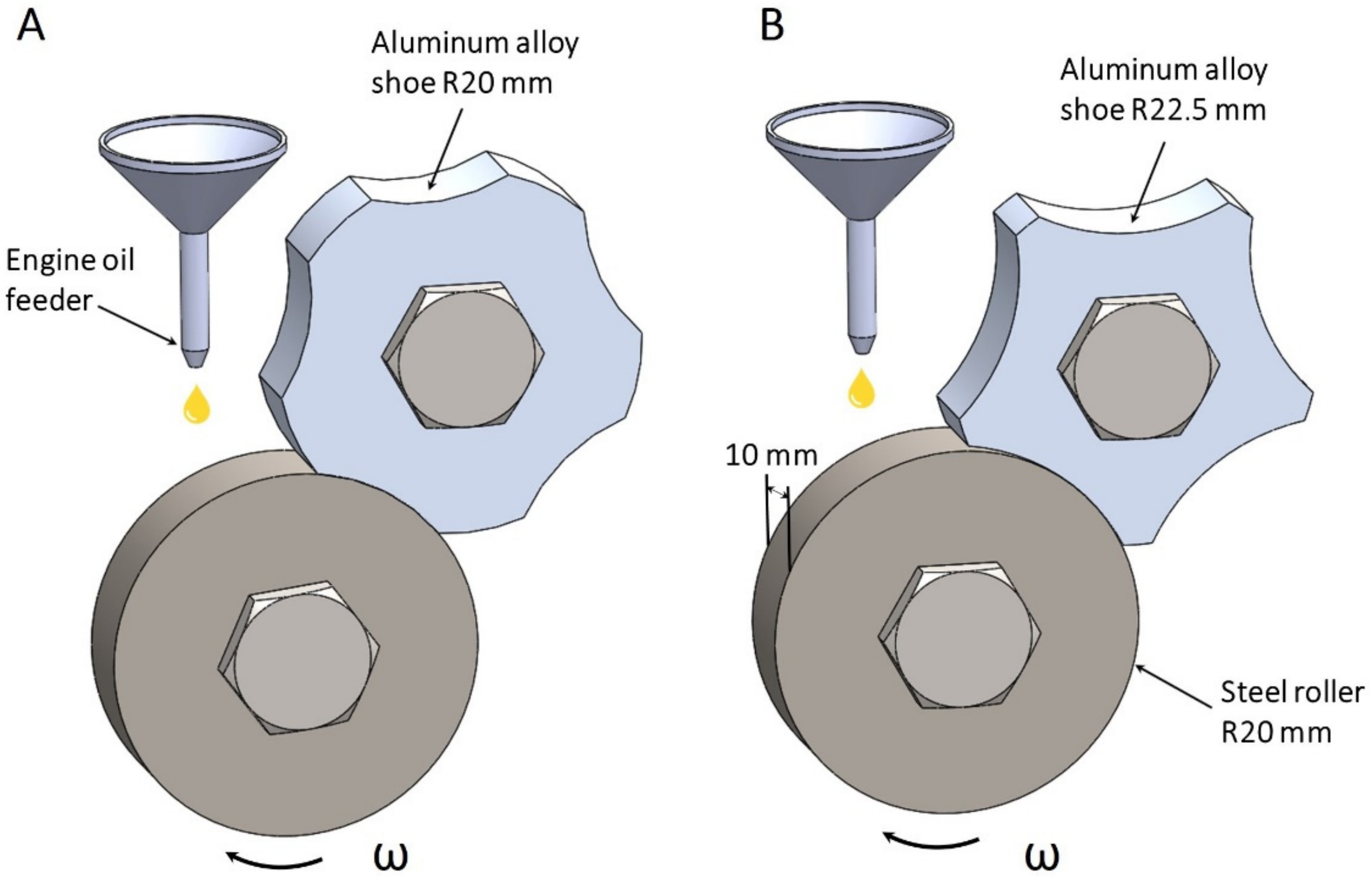
A “rotating roller-fixed shoe” type wear test was performed under mixed lubricated conditions in a friction machine “SMC-2” (Tochmashpribor, Ivanovo, Russia), using steel roller and being the Al-based alloy samples the materials tested (Figure 1).
The lubricant (M14V2 engine oil) supply rate and viscosity were 0.2 g/min and 14 mm2/s, respectively. Six characteristics for each sample were recorded: score-resistance, running-in ability, alloy wear, steel counter body wear, friction coefficient, and temperature.
The chemical composition of steel rollers with a diameter of 40 mm and a width of 10 mm is presented in Table 3.
The sample’s roughness (Ra) before wear tests was measured using stylus profilometer Hommel Tester T8000 (Hommelwerke GmbH, Villingen-Schwenningen, Germany) and the value was 0.8 µm. The steel roller rotational speed was 500 rpm for all experiments.

2.5.1. Score-Resistant Measurement

Before score-resistance tests the friction pair underwent running-in stage at the load of 304 N until 90–95% of contour area of contact is reached. The load during score-resistance tests applied gradually every 10 min starting by 137–187 N until the seizure is observed which was determined by either a step-like continuous increase in friction torque or an appearance of intensive smoke from the lubricant. Once the phenomena were detected, the tests were stopped and the current load value is taken as score-resistance. The general view of samples prepared for score-resistance test is shown in Figure 1A. A friction surface of a radius of 20 mm was obtained by milling sintered blank discs.

2.5.2. Wear Resistance Tests

Wear tests were preceded by the same running-in stage as in the case of score-resistance experiments. After that wear tests were performed for 40 h at the load of 617 N. Within the process six main parameters were monitored such as friction coefficient, the temperature on the roller surface, weight loss of the specimen, and the steel roller. To measure the temperature Testo 830-T2 pyrometer (Testo SE & Co. KGaA, Lenzkirch, Germany) was used. To determine weight loss, the steel roller and the aluminum alloy shoe were weighed before and after the tests on a calibrated analytical balance GR-300 (A&D, Tokyo, Japan) with an accuracy of 0.0001 g. All the specimens and rollers after wear tests were cleaned from lubricant residuals and waste with water and pure acetone in an ultrasonic bath for 20 min. Each test was repeated three times per specimen to ensure the statistical significance of the results obtained.

2.5.3. Running-in Ability

To evaluate the running-in ability of the materials, the specimens were tested at several loading values increased from 304 N to 1058 for 10 min at each stage according to the scheme shown in Figure 1B. Once a stage is completed the experiment was interrupted and a contact area was measured by a digital caliper (Mitutoyo, Kawasaki, Japan). Compared to the previous experiments, the radius of friction surface of the specimens is larger—22.5 mm (Figure 1B).
The above-mentioned tribotest conditions were performed on the borderline of frictional seizure in order to accelerate the formation process of secondary structures on the rubbing surfaces. Otherwise, it would take a very long time (several years) for the formation of secondary structures under normal operating conditions of a friction pair. Under the proposed in this work severe conditions the tribological characteristics of studied compositions were determined within 40 h. In these regimes, the lubricant inevitably undergoes decomposition [51] followed by tribopolymerization [52].
The studied multicomponent aluminum alloys are planned to be used as a material for monometallic plain bearings instead of bronze ones, which are extensively used due to optimal complex of mechanical and tribological properties. Therefore, it is of particular interest to compare their properties. That is why for comparison purposes the bronze Cu-4Sn-4Zn-17Pb was chosen due to outstanding tribological properties among other alloys, that are used for the manufacture of journal bearings. The reference material was tested using the same equipment and under the same conditions as those used for Al-based alloys.

3. Results and Discussion

3.1. Microstructure Characterization of Al-Mo Alloy

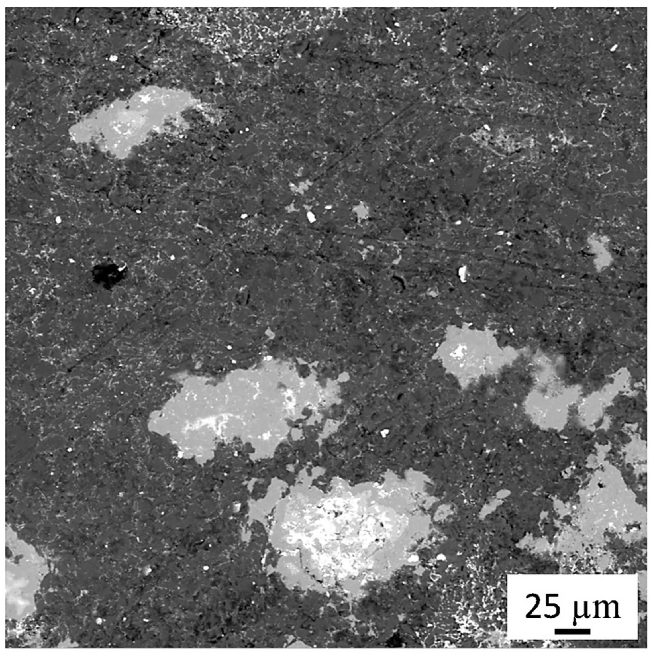
The microstructure of the sintered and polished Al–Mo alloy is presented in Figure 2.
Table 4 shows the chemical composition of the sintered Al–Mo alloy resulting from the EDS analysis.
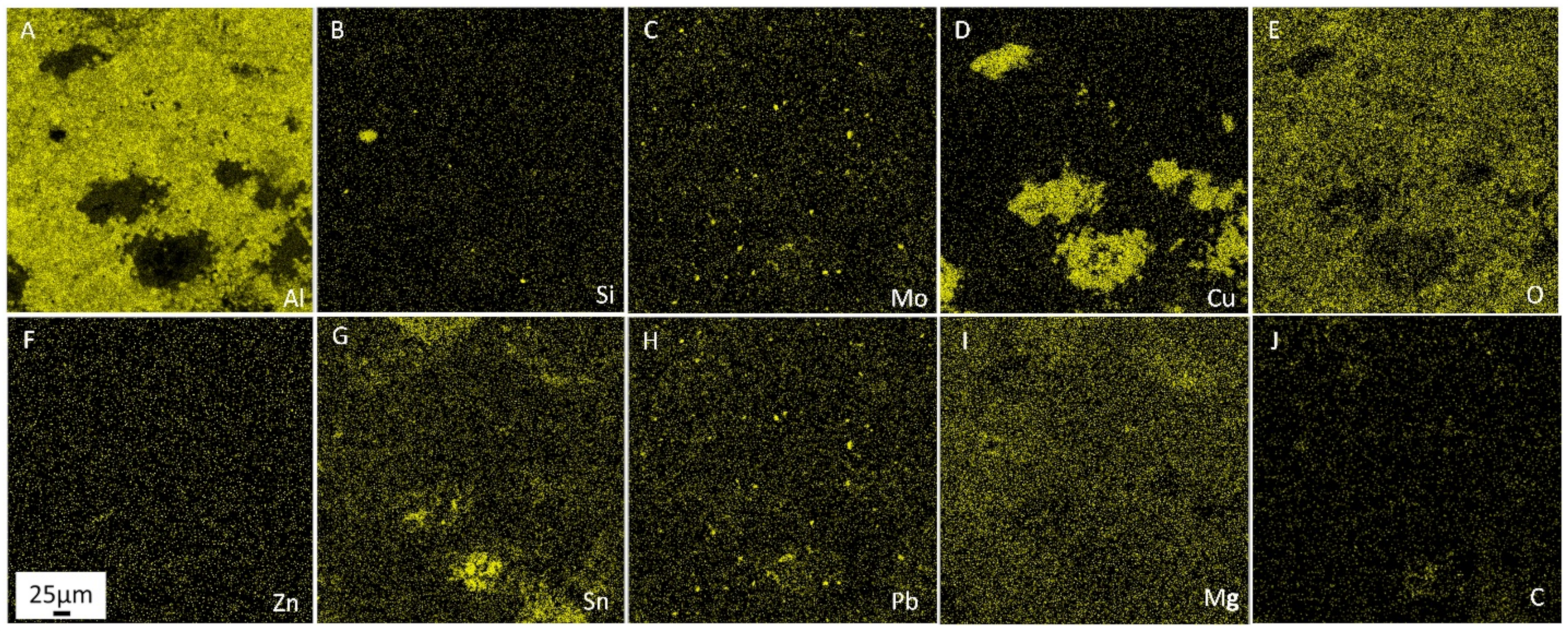
Figure 3 shows SEM-EDS elemental distribution maps in the Al–Mo alloy.
The microstructure of SPS-ed Al–Mo alloy presents an aluminum matrix with a varying diverse set of hard and soft phase inclusions. Small inclusions of silicon (Figure 3B) and molybdenum (Figure 3C), magnesium (Figure 3I), and zinc (Figure 3F) particles were uniformly distributed in the sintered composite. The presence of θ-phase (CuAl2), which was also alloyed with zinc, magnesium, tin, and lead, was found. Aluminum interacts with Cu, Si, and Mo, characterized by small equilibrium inclusions. The existence of alumina and small inclusions of solid phases in the tin-lead phases (Figure 3G,H) were observed. Zinc does not form phases and has a relatively homogeneous distribution with some areas of high concentration related to Cu. More detailed information concerning the microstructure characterization, EDS chemical identification of elements, and their concentration in Al–Mo alloy was provided in the previous study [48].

3.2. Microstructure Characterization of Al–Cr Alloy

Figure 4 shows microstructure with the EDS spectra of sintered Al–Cr alloy.
Table 5 below shows the chemical composition of SPS-ed Al–Cr alloy using the EDS technique.
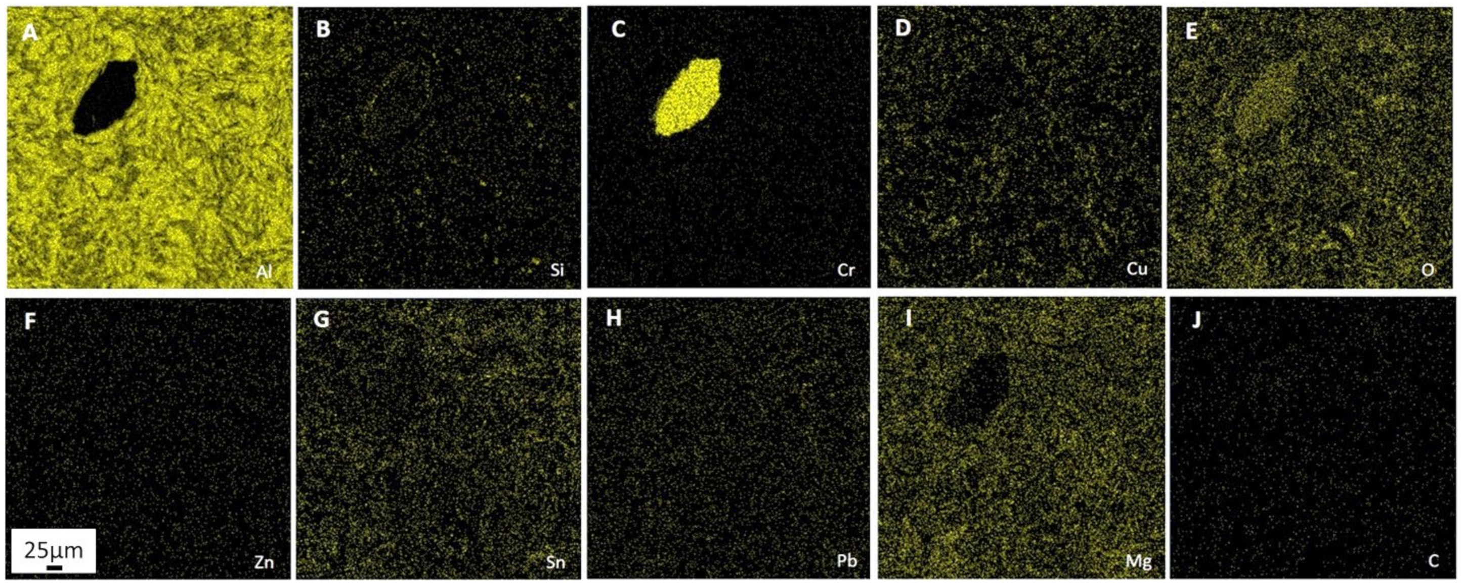
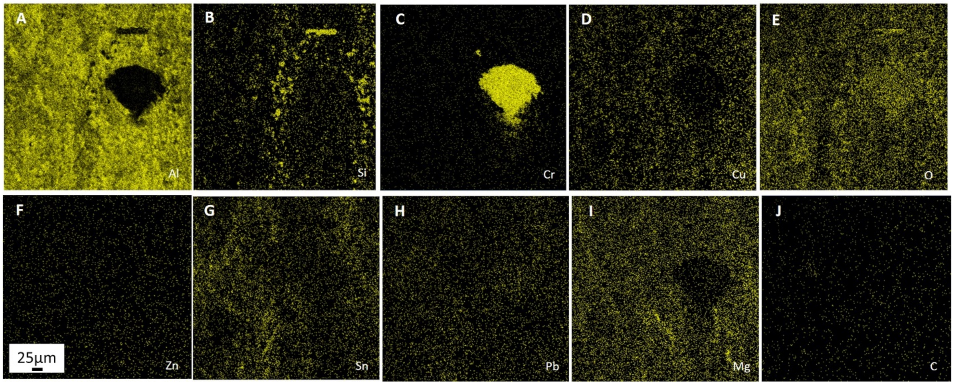
Figure 5 shows SEM-EDS elemental distribution maps in the Al–Cr alloy.
The basis of this composition is aluminum matrix alloyed by Сu and Zn (Figure 5D,F). Besides these elements, areas containing Si, Mg, Sn, and Pb (Figure 5B,G–I).
The material provided indicates that aluminum particles (Figure 5A) around chromium-based inclusion (Figure 5C) were deformed more intensively than away from the Cr inclusion.
Practically all particles are delineated by elongated inclusions of aluminum combined with oxygen (Figure 5E), copper (Figure 5D), or tin (Figure 5G). Magnesium is characterized by an increase in content in certain zones of the matrix and some inclusions, with little presence in other types of inclusions (Figure 5I). Lead (Figure 5H) and zinc (Figure 5F) are relatively evenly distributed. The presence of small inclusions and an increase in the content on the side surfaces of Cr inclusion were observed for silicon (Figure 5B). As regards carbon (Figure 5J) no patterns of distribution on the polished surface were observed because in the original state it practically does not exist and only the background of carbon is recorded.
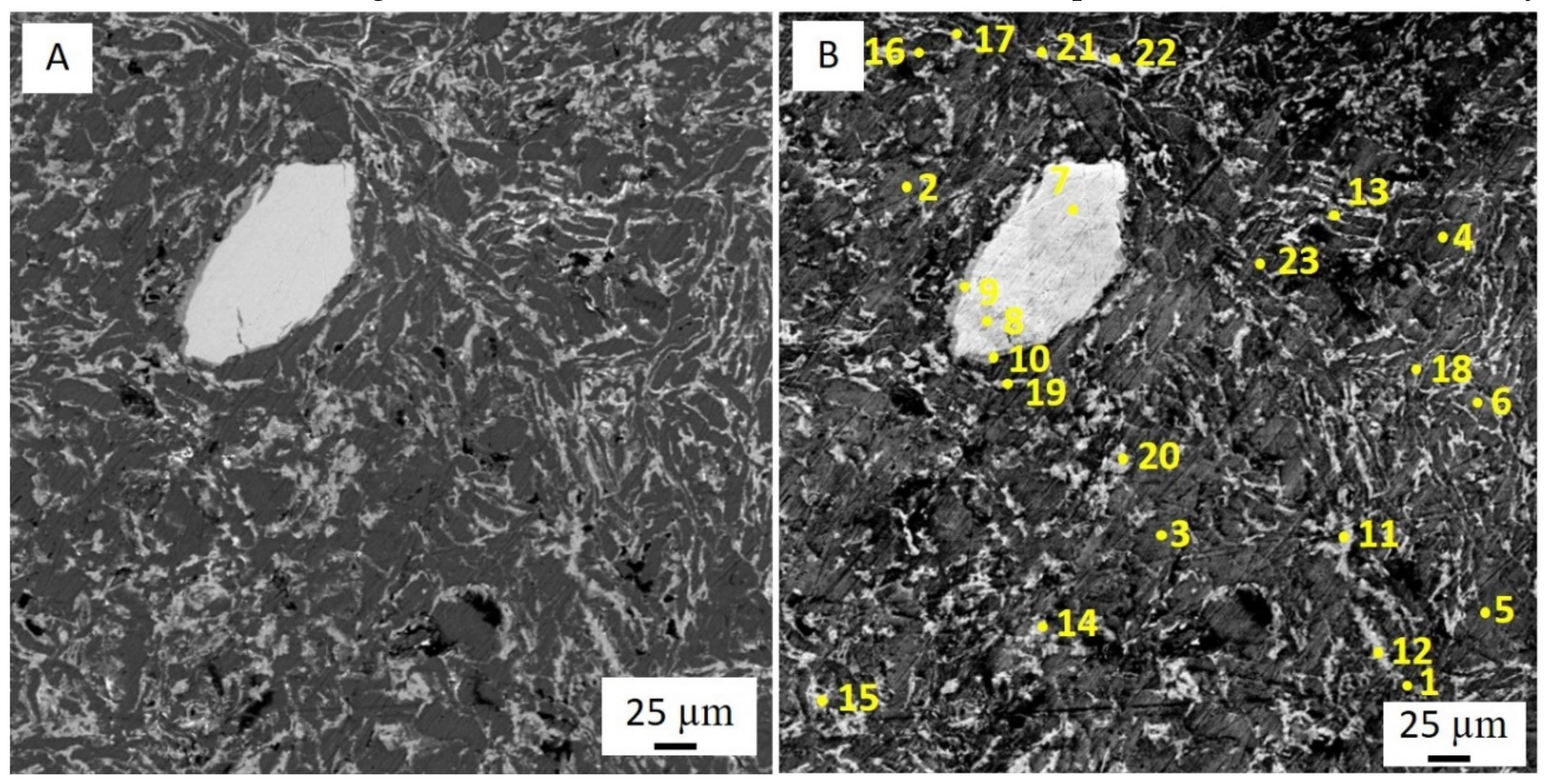
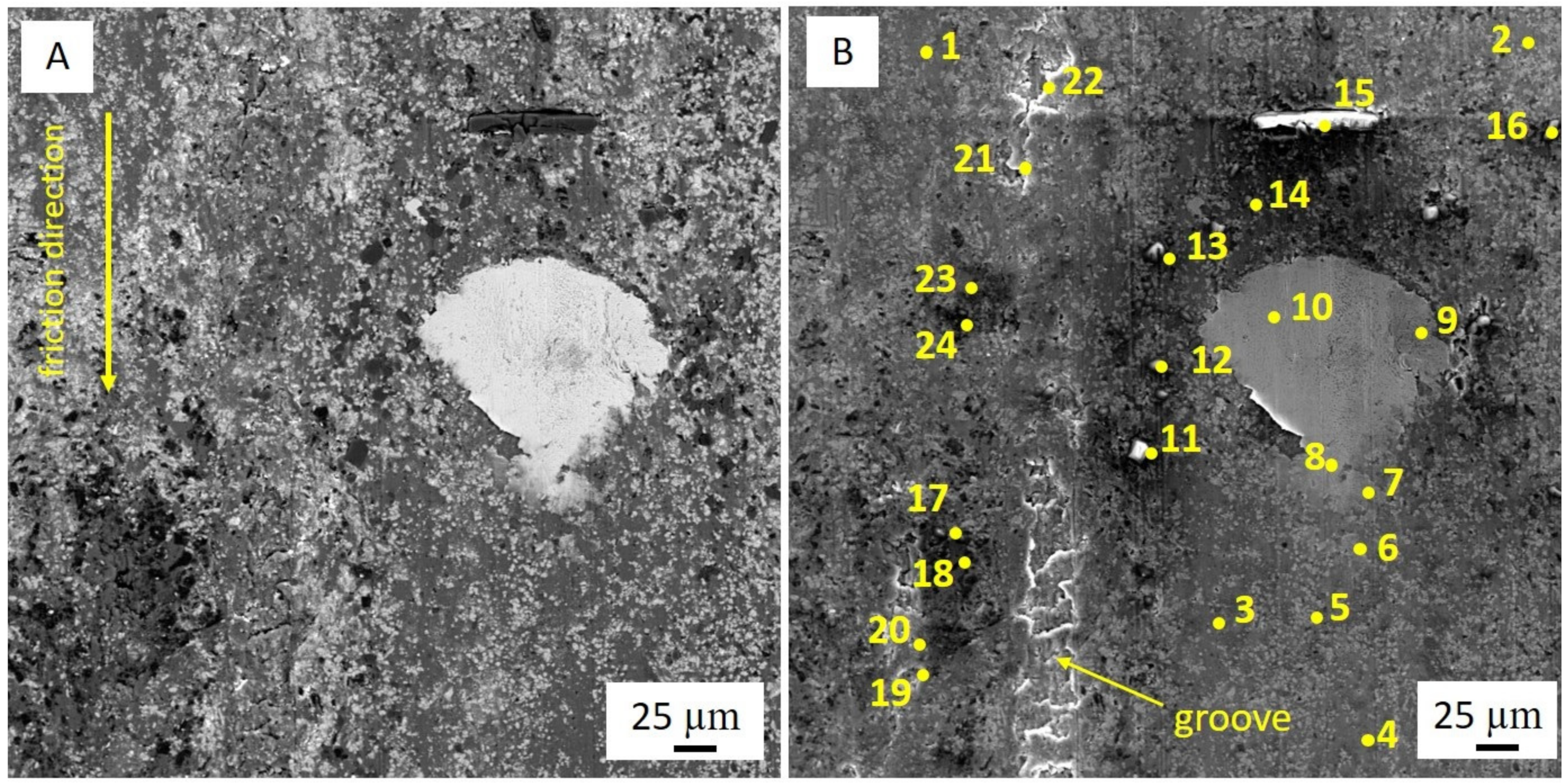
The phase composition of Al–Cr alloy was determined using 23 analyses at randomly selected EDS spectra of local analyzes at 23 different points, according to the scheme presented in Figure 4B. EDS elements concentration data of the Al–Cr alloy are reported in Table 6.
This composition is characterized by the presence of an Al matrix (spectra 2–6, 23) alloyed by Cu (1.45–2.94%) and Zn (1.76–2.14%). In addition, local areas with Si (0–33%), Mg (0–1.25%), Sn (0–2.45%) and Pb (0–0.99%) were detected.
Most Al-matrix parts reacted weakly with O: 2.34–7.16%, although there are also some small inclusions of the aluminum oxide (spectra 1, 17, 21, 22). The existence of phases based on a solid solution of aluminum in Ѳ-phase (CuAl2), which have further alloyed with Sn, Pb, Mg, Si, O, and C (spectra 11–22) were observed.
It should be noted, however, that these phases differ the low (Al: 45.36–50.95%, Cu: 22.06–33.17%, Sn: 2.64–6.86%, Pb: 1.04–5.10%, Mg: 1.93–4.47%, Zn: 0.70–1.19%, Si: 0–0.27%%, O: 9.23–13.32%, C: 1.62–2.25%) and high (Al: 31.35–43.58%, Cu: 6.32–25.67%, Zn: 0.52–1.10%, Si: 0–0.18%, Mg: 4.46–8.74%, Sn: 7.14–19.42%, Pb: 1.18–5.00%, Cr: 0–0.22%, C: 1.07–1.75%, O: 14.66–23.81%) contents of Sn, respectively. For this alloy, it is difficult to talk about the presence of a soft structural phase in the ordinary understanding, as individual Sn- and Pb-based large inclusions. Their maximum total quantity (spectrum 21) does not exceed 23 wt.%. On the other hand, the presence of numerous small inclusions of these types combined with the solid solution based on the Ѳ-phase may significantly affect and improve the efficiency of the antifriction properties of Al–Cr alloy. It should also be noted that phases without Sn but with Pb were not found.
Cr-based inclusions (spectra 7–10) contain the following elements: 0.17–50.6%, Cu: 0–8.66%, Si: 0–5.70%, Mg: 0–0.49%, Sn: 0–0.96%, Cr: 29.59–96.66%, O: 1.70–3.62%, C: 0–1.93%, Fe: 0–0.39%.
Unlike Mo in Al–Mo alloy in this composition the Cr particles not only vary in size, but they also have numerous cracks. Perhaps these particles could be ground by changing the milling time during the processing stage.
The surface of Cr-based particles underwent mechanical alloying with the formation of a new Al-based phase with high content of Cr and Si (spectra 9) which have further reacted with Cu, Sn, Mg, and Fe.

3.3. Mechanical Properties of the Sintered Alloys

The density and mechanical properties of all studied materials are presented in Table 7. The SPS-ed alloys are outperformed in hardness to bronze, but slightly inferior in strength.
The essential content of oxygen 15.86 (Table 4) and 14.43% (Table 5) for Al–Mo and Al–Cr alloys, respectively, had a major impact on the mechanical behavior.
On the one hand, most of the oxygen was jointed with Al, the solid inclusions of which caused an increase in hardness. On the other hand, these inclusions reduce the contact area between aluminum particles, thus decreasing the strength compared to the bronze.
The difference in strength between Al–Mo and Al–Cr alloys is largely associated with the presence of Mo and Cr. Molybdenum particles are small and monolithic [21], while Cr particles were not involved in mechanical alloying, but during milling, cracks appeared in them (Figure 4A). Therefore, Mo was practically not a stress concentrator, but Cr increases the stress concentration due to particles size and presence of cracks that lead to a reduction in the strength of Al–Cr alloy. In addition, matrix and solid inclusions in Al–Mo composition were alloyed by Mo, whereas this behavior was not observed for Cr in Al–Cr alloy. For this reason, composition with Mo is stronger and harder than a composition with Cr.

3.4. Tribological Behaviour

These experimental results are reported in Table 8. The density of bronze was nearly three times that of the sintered alloys, thus for wear comparison weighting values were recalculated into linear wear.
The table shows that sintered compositions demonstrate a lower value of the weight and linear wear by 9 and 3, and 4.5 and 1.5 times for Al–Mo and Al–Cr alloy, respectively, than bronze.
The wear rate of the steel counter body was three times less for Al–Mo alloy than the bronze or Al–Cr alloys, although the temperature of steel surface during experiments was almost the same. The friction coefficient for Al–Cr composition was two times lower and 12% less than for bronze and Al–Mo, respectively. These results support the conclusions claim that the value of friction coefficients is not a major criterion of materials wear resistance, which was reached in the previous study [48].
The running-in ability of Al–Cr alloy was more than 2.0 and 1.6 times higher than that of bronze and Al–Mo composition, respectively. Thus, the contact area of Al–Cr alloy is 1.6 times bigger than that of the bronze specimen or Al–Mo alloy. The Al–Mo alloy showed the highest score-resistance compared to the bronze (2.6 times more) and Al–Cr alloy (1.7 times more). Consequently, the SPS-ed alloys outperform the bronze on all tribological properties, except for the steel wear rate for Al–Cr composition.
Meanwhile, the Al–Mo alloy is superior to the Al–Cr alloy in terms of the score- and wear resistance and also shows a lower wear rate of the steel counter body. On the other side, Al–Cr alloy demonstrates better running-in ability and lower friction coefficient compared to Al–Mo composition.
The obtained tribological properties of these alloys are due to the ability to form various secondary structures on wear surfaces during friction. Those structures are a product of the adaptation and self-organization of sintered alloys to the triboprocesses.

3.5. Study of the Secondary Structures on the Worn Surface of the Al–Mo Alloy

Figure 6 shows SEM micrographs in the backscattered electron (BSE) and secondary electron (SE) mode of the worn surface of the Al–Mo alloy.
The elemental composition of the Al–Mo alloy friction surface was determined by EDS and presented in Table 9.
Unlike the sintered sample (Table 4) this surface is characterized by high Sn and Mg content, the appearance of marked elements concentration from lubricant (chlorine (Cl), sulfur (S), and calcium (Ca)), increased levels of Al, Si, and Mo while reduced Pb, Cu, Zn, and C.
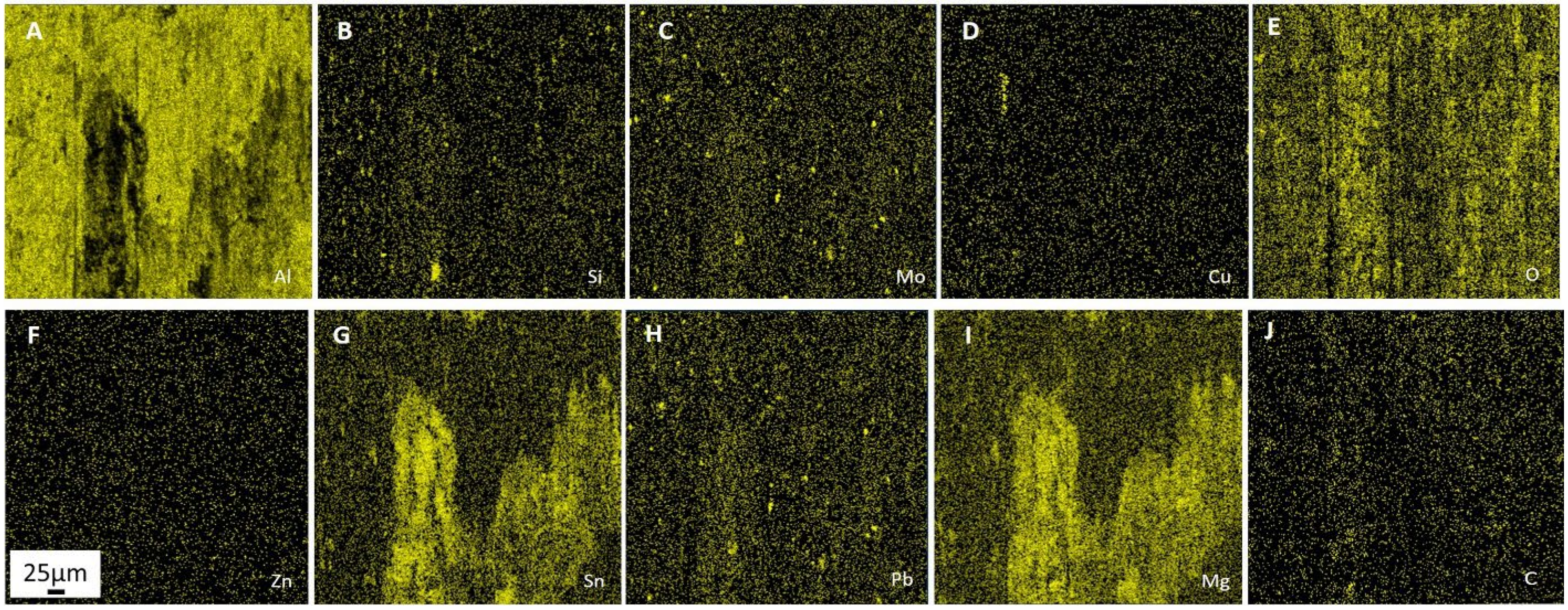
Figure 7 shows the SEM-EDS maps of elemental distributions on the Al–Mo alloy worn surface.
Table 10 below shows the 32 EDS points analysis data and the concentration of the element in the Al–Mo composition in accordance with the scheme presented in Figure 6B.
The composition of the local zones with an increased level of Al (Figure 7A) very much depends not only on the mechanical alloying process but also on the thickness of the secondary structures film on the Al particles surface (spectra 1–5, 7, 8, 10, 12–14, 31) and the existence of inclusions of Mo and Si (Figure 7C,B). There is increasing copper content likely due to the presence of fine particles of Ѳ-phase or an abnormally high level of alloying of Al with copper (spectra 8 and 13). In both cases, for friction, these zones are elements of the Charpy structure and should contribute to an increase in the specific load and the creation of an oil-retaining layer.
On the other hand, the copper level (Figure 7D) is not more than 20% (spectra 6 and 11), so it is impossible to speak of full Ѳ-phase in secondary structures of the Al–Mo alloy. This makes it possible to classify these inclusions as a solid solution of aluminum in CuAl2.
Analysis of spectra 15, 16, 19–21, 24, 26, 27–30, 32 shows the presence of a soft structural component in the alloy, which is represented by inclusions and films based on tin (Figure 7G), magnesium (Figure 7I) and lead (Figure 7H).
These phases, usually (except for spectrum 19), are poorly carburized but contain a significant amount of oxygen. The thinner is the precipitation of soft phases, the higher the content of Al in the spectrum.
The areas of increased and decreased carbon concentration (Figure 7J) on the Al–Mo alloy friction surface were found. This reveals a formation of polymer components in protective films of secondary structures. The areas in the polymer component of secondary structures (spectra 9, 17, 18, 19, 22, 23, 30) where the carbon content exceeds the concentration of oxygen, were not found.
For oxygen (Figure 7E) the relationship distribution with friction direction is stronger, while for carbon (Figure 7J) this relationship is a less marked and more rounded zone with higher concentration is detected, which is likely due to porosity and depressions in the friction surface.

3.6. Study of the Secondary Structures on the Worn Surface of the Al–Cr Alloy

A study similar to the Al–Mo alloy was carried out on the worn surface of Al–Cr in BSE (Figure 8A) and SE (Figure 8B) mode.
The elemental composition of the Al–Cr alloy friction surface was determined by EDS and presented in Table 11.
Comparing with a sintered composition (Table 5) shows differences in concentration of basic elements, and appearance of new elements on the worn surface from lubricant (chlorine, sulfur, and phosphorus) and steel counter body (Ferrum).
Obtained results show that elements that form solid and soft phases have an important role in the formation of secondary structures. In addition, the role of the polymer component formed during the decomposition of the lubricant also increases. A significant presence of sulfur, chlorine, calcium, and phosphorus in lubricant points to the activity of these processes. The 0.38% Ferrum content (Table 11) reveals average synergies between steel and sintered alloys.
Figure 9 shows the SEM-EDS maps of elemental distributions on the Al–Cr alloy worn surface.
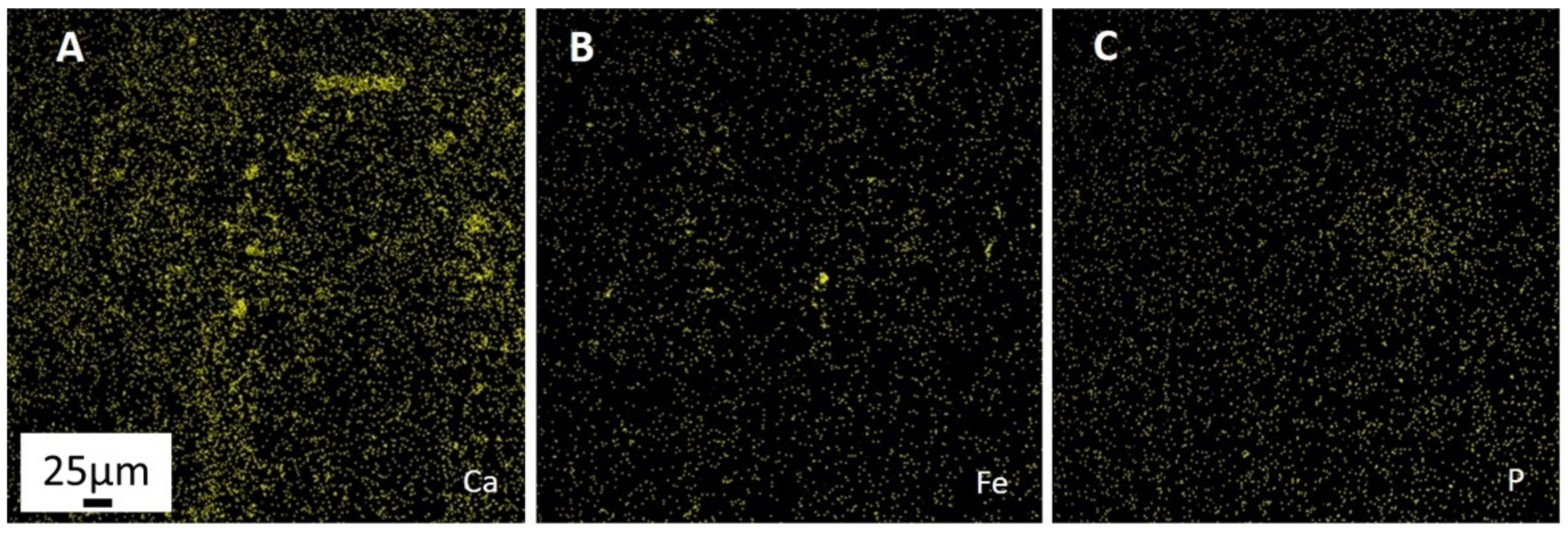
Almost complete absence of aluminum inside of large inclusions and its low level in wear groove was observed according to the EDS distribution map (Figure 9A). Large inclusion in the upper part of Figure 9C consists mostly of Cr. In the bottom half of this inclusion interaction between Cr and Al with the gradual enhancement of concentration of the latter is occurred. Chromium inclusion is surrounded by numerous small silicon inclusions (Figure 9B), that have interacted with calcium (Figure 10A).
Ferrum-based inclusions (Figure 10B) are much less and smaller. Many small inclusions of steel are in the groove, which suggests that the steel particle was the abrasive that formed it. This groove reacted weakly with tin (Figure 9G) and copper (Figure 9D). In addition, even fewer of these elements on the surface of chromium inclusion were found. This surface is magnesium-depleted (Figure 9I) but enriched by oxygen (Figure 9E) and phosphorus (Figure 10C). These findings are supported by the results of randomly selected EDS spectra of local analyzes at 24 different points (Table 12) according to the scheme presented in Figure 8B.
Spectra 1, 4–6, 20 and 22 can be attributed to the aluminum matrix and weakly reacted with oxygen (less than 10%) and did not react with carbon at all. Matrix areas (spectra 2, 3, and 19) with average oxygen content (10–20%) also contain no more than 0.1% carbon. Strongly oxidized matrix areas (spectra 11–16 and 18) with high oxygen content (20–60%) are also practically not carburized. The criterion for the presence of a metal-polymer film on the surface is the presence of carbon and oxygen simultaneously on the aluminum matrix of the alloy in the C/O ratio equal to 0.75 to 3. This ratio was found only in one zone (spectrum 21) where it was 0.75. In another spectrum (17) this ratio is 0.25. Only in these two places, this film has attributes of metal-polymer film. In most areas, the film that covers the aluminum particles is oxide, not polymer. The thickest film was formed in the maximum contact area with steel (spectrum 21), as confirmed by high iron level (0.71% Fe) and such elements as sulfur, calcium, and phosphorus from a decomposed lubricant. Furthermore, as a rule, the matrix is covered with a film consisting of Sn, Mg, and Pb in combination with oxygen and carbon (spectra 2–6, 17–23). Of particular interest are analyses of local zones of chromium inclusion and around it (spectra 5–10). The interior of the inclusion is pure Cr doped with Al, Mg, and Cu from the surface and covered by polymer film based on decomposed lubricant. The bottom part of inclusion increased the content of Al, Cu, Zn, and Mg with distance from the center in the direction of friction, which shows the interaction between θ-phase and Al with Cr during friction. The formation of the film based on solid lubricant is confirmed by increasing Sn and Pb content. Meanwhile, this increases oxygen content, but the level of carbon remains unchanged. Consequently, oxidative friction prevails over the formation of the polymer film. Inclusions with a high level of Si (spectra 11–16) represent aluminum and silicon oxides reacted with Cu, Zn, and Mg during mechanical alloying. All of them had reacted with Ca, partly with P and S, were covered with thin tin film during friction. The almost total absence of carbon, chromium, and lead is typically for these inclusions.

4. Conclusions

In this work, the influence of the presence of Mo and Cr on the mechanical and tribological properties of the multicomponent aluminum-based alloy, prepared by mechanical alloying and sintered by SPS, was investigated.
According to the mechanical test results, it was observed that the hardness of SPS-ed alloys was improved, while the strength decreased, compared to bronze. The maximum hardness and strength values obtained were 73 and 134 MPa, 72 and 125 MPa for the Al–Mo and Al–Cr alloys, respectively. Meanwhile, the hardness and strength values of bronze were 65 and 148 MPa, respectively.
The tribological tests showed that the sintered alloys outperformed bronze in weight and linear wear by 9 and 3 times for the Al–Mo alloys and 4.5 and 1.5 times for Al–Cr alloys, respectively. The Al–Mo alloy exhibited the highest score-resistance compared to the bronze (2.6 times more) and Al–Cr alloy (1.7 times more).
Moreover, the Al–Mo alloy wears out the steel counter body 3 times less than the bronze and Al–Cr compositions. However, the latter alloy had the lowest friction coefficient of 0.084, which is two times lower than that of bronze and also 12% better than the Al–Mo. The obtained results for both Al-based alloys can be attributed to the presence of various constituents in pristine SPS-ed structures that contribute to the formation of secondary structures on the friction surfaces of rubbing pairs, which in turn reduces wear.
Molybdenum played an active part in the mechanical alloying of matrix and phases of solid inclusions during the milling stage, resulting in phases strengthening and remaining inclusions of Mo were small to influence as stress concentrators. The Al–Mo alloy showed a great ability for self-organization on the friction surface with the formation of advantageous secondary structures. The formation processes of protective films with the presence of carbon, oxygen, tin, lead, and magnesium, where the main role played soft metallic component (solid lubricant) based on Sn and Mg is typical for this alloy. This solid lubricant was strengthened by other alloying elements and actively interacted with engine oil constituents (carbon, oxygen, chlorine, sulfur, and calcium) on the friction surface of the Al–Mo alloy.
Lower mechanical and tribological properties of the Al–Cr alloy are due to the weak interaction of Cr with other structural components of the composition. This prompts the conclusion that it is much preferable to use chromium powder with fine particle fraction so that most of the particles could react during the self-organization process since coarse Cr particles are almost excluded from the formation processes of secondary structures. In this regard, it is important to note that self-organization and hence the generation of secondary structures are different for alloys with different content of elements.
Further studies are needed for the determination of the optimal content of molybdenum in antifriction aluminum alloys with an enhanced set of mechanical and tribological properties.

Author Contributions

Conceptualization, S.N.G., A.S. and A.M.; data curation, E.K. and Y.P.; formal analysis, P.P. (Pavel Peretyagin), P.P. (Pavel Podrabinnik) and N.W.S.P.; funding acquisition, S.N.G. and A.S.; investigation, P.P. (Pavel Podrabinnik) and Y.P.; methodology, N.W.S.P. and I.G.; project administration, A.S. and A.M.; resources, I.G. and P.P. (Pavel Podrabinnik); software, P.P. (Pavel Podrabinnik) and I.G.; supervision, S.N.G., A.S. and A.M.; validation, Y.P. and E.K.; visualization, P.P. (Pavel Peretyagin), P.P. (Pavel Podrabinnik) and E.K.; writing—original draft, A.S. and E.K. All authors have read and agreed to the published version of the manuscript.

Funding

This research was funded by the Russian Science Foundation, grant number 21-79-30058.

Institutional Review Board Statement

Not applicable.

Informed Consent Statement

Not applicable.

Data Availability Statement

The data described in this article are openly available in the previous works.

Acknowledgments

The study was carried out on the equipment of the Center of collective use of MSUT “STANKIN” (project 075-15-2021-695).

Conflicts of Interest

The authors declare no conflict of interest.

References

  1. Abd El-Salam, F.; Abd El-Khalek, A.M.; Nada, R.H.; Wahab, L.A.; Zahran, H.Y. Effect of Sn content on the structural and mechanical properties of Al-Si alloy. Mater. Sci. Eng. A 2010, 527, 1223–1229. [Google Scholar] [CrossRef]
  2. Abd El-Salam, F.; Abd El-Khalek, A.M.; Nada, R.H.; Wahab, L.A.; Zahran, H.Y. Thermally induced structural and mechanical variations in ternary Al–Si based alloys. Mater. Sci. Eng. A 2009, 527, 281–286. [Google Scholar] [CrossRef]
  3. Yuan, G.C.; Li, Z.J.; Lou, Y.X.; Zhang, X.M. Study on crystallization and microstructure for new series of Al-Sn-Si alloys. Mater. Sci. Eng. A 2000, 280, 108–115. [Google Scholar] [CrossRef]
  4. Ahn, S.S.; Pathan, S.; Koo, J.M.; Baeg, C.H.; Jeong, C.U.; Son, H.T.; Hong, S.J. Enhancement of the mechanical properties in Al–Si–Cu–Fe–Mg alloys with various processing parameters. Materials 2018, 11, 2150. [Google Scholar] [CrossRef] [PubMed] [Green Version]
  5. Sobol’, O.V.; Andreev, A.A.; Grigoriev, S.N.; Gorban’, V.F.; Volosova, M.A.; Aleshin, S.V.; Stolbovoi, V.A. Effect of high-voltage pulses on the structure and properties of titanium nitride vacuum-arc coatings. Met. Sci. Heat. Treat. 2012, 54, 195–203. [Google Scholar] [CrossRef]
  6. Vereschaka, A.A.; Grigoriev, S.N.; Vereschaka, A.S.; Popov, A.Y.; Batako, A.D. Nano-scale multilayered composite coatings for cutting tools operating under heavy cutting conditions. Procedia CIRP 2014, 14, 239–244. [Google Scholar] [CrossRef] [Green Version]
  7. Ren, S.; Zheng, S.; Pu, J.; Lu, Z.; Zhang, G. Study of tribological mechanisms of carbon-based coatings in antiwear additive containing lubricants under high temperature. RSC Adv. 2015, 5, 66426–66437. [Google Scholar] [CrossRef]
  8. Summer, F.; Grün, F.; Ravenhill, E.R. Friction and wear performance of various polymer coatings for journal bearings under stop start sliding. Lubricants 2019, 8, 1. [Google Scholar] [CrossRef] [Green Version]
  9. Metel, A.; Bolbukov, V.; Volosova, M.; Grigoriev, S.; Melnik, Y. Source of metal atoms and fast gas molecules for coating deposition on complex shaped dielectric products. Surf. Coat. Technol. 2013, 225, 34–39. [Google Scholar] [CrossRef]
  10. Vereschaka, A.S.; Grigoriev, S.N.; Tabakov, V.P.; Sotova, E.S.; Vereschaka, A.A.; Kulikov, M.Y. Improving the efficiency of the cutting tool made of ceramic when machining hardened steel by applying nano-dispersed multi-layered coatings. Key Eng. Mater. 2014, 581, 68–73. [Google Scholar] [CrossRef]
  11. Vereschaka, A.; Tabakov, V.; Grigoriev, S.; Sitnikov, N.; Andreev, N.; Milovich, F. Investigation of wear and diffusion processes on rake faces of carbide inserts with Ti-TiN-(Ti,Al,Si)N composite nanostructured coating. Wear 2018, 416–417, 72–80. [Google Scholar] [CrossRef]
  12. Grigoriev, S.N.; Vereschaka, A.A.; Fyodorov, S.V.; Sitnikov, N.N.; Batako, A.D. Comparative analysis of cutting properties and nature of wear of carbide cutting tools with multi-layered nano-structured and gradient coatings produced by using of various deposition methods. Int. J. Adv. Manuf. Technol. 2017, 90, 3421–3435. [Google Scholar] [CrossRef]
  13. Marrocco, T.; Driver, L.C.; Harris, S.J.; McCartney, D.G. Microstructure and properties of thermally sprayed Al-Sn-based alloys for plain bearing applications. J. Therm. Spray Technol. 2006, 15, 634–639. [Google Scholar] [CrossRef]
  14. Kotadia, H.R.; Das, A.; Doernberg, E.; Schmid-Fetzer, R. A comparative study of ternary Al-Sn-Cu immiscible alloys prepared by conventional casting and casting under high-intensity ultrasonic irradiation. Mater. Chem. Phys. 2011, 131, 241–249. [Google Scholar] [CrossRef]
  15. Lu, Z.C.; Gao, Y.; Zeng, M.Q.; Zhu, M. Improving wear performance of dual-scale Al-Sn alloys: The role of Mg addition in enhacing Sn distribution and tribolayer stability. Wear 2014, 309, 216–225. [Google Scholar] [CrossRef]
  16. Yan, L.; Zhang, Y.; Li, X.; Li, Z.; Wang, F.; Liu, H.; Xiong, B. Effect of Zn addition on microstructure and mechanical properties of an Al–Mg–Si alloy. Prog. Nat. Sci. Mater. Int. 2014, 24, 97–100. [Google Scholar] [CrossRef] [Green Version]
  17. Savaşkan, T.; Bican, O.; Alemdağ, Y. Developing aluminium–zinc-based a new alloy for tribological applications. J. Mater. Sci. 2009, 44, 1969–1976. [Google Scholar] [CrossRef]
  18. Fang, L.; Zhang, X.; Ren, L.; Hu, H.; Nie, X.; Tjong, J. Effect of Ni addition on tensile properties of squeeze cast Al alloy A. Adv. Mater. Process. Technol. 2017, 4, 200–209. [Google Scholar] [CrossRef]
  19. Rajaram, G.; Kumaran, S.; Rao, T.S. Effect of graphite and transition elements (Cu, Ni) on high temperature tensile behaviour of Al–Si Alloys. Mater. Chem. Phys. 2011, 128, 62–69. [Google Scholar] [CrossRef]
  20. Rusin, N.M.; Skorentsev, A.L.; Kolubaev, E.A. Structure and tribotechnical properties of Al-Sn alloys prepared by the method of liquid-phase sintering. Adv. Mater. Res. 2014, 1040, 166–170. [Google Scholar] [CrossRef]
  21. Guo, Q.; Chen, J.; Li, J.; Huo, Y.; Yang, Z.; Yang, W.; Xu, D.; Yang, B. Oxidation mechanism of Al-Sn bearing alloys. Materials 2021, 14, 4845. [Google Scholar] [CrossRef] [PubMed]
  22. Zeng, M.; Lu, Z.; Chen, J.; Song, K.; Hu, R.; Zhu, M. Research progress on Al-based sliding bearing alloys. Mater. Mechancial Eng. 2018, 42, 7–14. [Google Scholar]
  23. Busch, C. Solid Lubrication. In Lubricants and Lubrication; Mang, T., Dresel, W., Eds.; Wiley-VCH Verlag GmbH & Co. KGaA: Weinheim, Germany, 2006; Volume 17, pp. 694–714. [Google Scholar]
  24. Noskova, N.I.; Korshunov, L.G.; Korznikov, A.V. Microstructure and tribological properties of Al-Sn, Al-Sn-Pb, and Sn-Sb-Cu alloys subjected to severe plastic deformation. Met. Sci. Heat Treat. 2008, 50, 593–599. [Google Scholar] [CrossRef]
  25. Sharma, V.K.; Singh, R.C.; Chaudhary, R. Experimental study of sliding wear behavior of the casted lead bronze journal bearing material. In Proceedings of the WCX SAE World Congress Experience, Detroit, MI, USA, 9–11 April 2019. [Google Scholar]
  26. An, J.; Liu, Y.; Lu, Y.; Sun, D. Hot roll bonding of Al–Pb-bearing alloy strips and steel sheets using an aluminized interlayer. Mater. Charact. 2001, 47, 291–297. [Google Scholar] [CrossRef]
  27. Zhu, M.; Gao, Y.; Chung, C.; Che, Z.; Luo, K.; Li, B. Improvement of the wear behaviour of Al–Pb alloys by mechanical alloying. Wear 2000, 242, 47–53. [Google Scholar] [CrossRef]
  28. Nassef, A.; El-Garaihy, W.H.; El-Hadek, M. Mechanical and corrosion behavior of Al-Zn-Cr family alloys. Metals 2017, 7, 171. [Google Scholar] [CrossRef] [Green Version]
  29. Shaha, S.K.; Czerwinski, F.; Kasprzak, W.; Friedman, J.; Chen, D.L. Ageing characteristics and high-temperature tensile properties of Al–Si–Cu–Mg alloys with micro-additions of Cr, Ti, V and Zr. Mater. Sci. Eng. A 2016, 652, 353–364. [Google Scholar] [CrossRef]
  30. Szymczak, T.; Gumienny, G.; Pacyniak, T. Effect of vanadium and molybdenum on the crystallization, microstructure and properties of hypoeutectic silumin. Arch. Foundry Eng. 2015, 15, 81–86. [Google Scholar] [CrossRef]
  31. Pisarek, B.P. The crystallization of the aluminum bronze with additions of Si, Cr, Mo and/or W. Arch. Mater. Sci. Eng. 2007, 28, 461–466. [Google Scholar]
  32. Zhu, J.M.; Fu, H.M.; Zhang, H.F.; Wang, A.M.; Li, H.; Hu, Z.Q. Microstructures and compressive properties of multicomponent AlCoCrFeNiMox alloys. Mater. Sci. Eng. 2012, 527, 6975–6979. [Google Scholar] [CrossRef]
  33. Xu, Y.; Zheng, Q.; Geng, J.; Dong, Y.; Tian, M.; Yao, L.; Dearn, K.D. Synergistic effects of electroless piston ring coatings and nano-additives in oil on the friction and wear of a piston ring/cylinder liner pair. Wear 2019, 64, 201–211. [Google Scholar] [CrossRef]
  34. Totten, G.E.; Xie, L.; Funatani, K. Modeling and Simulation for Material Selection and Mechanical Design; Marcel Dekker, Inc.: New York, NY, USA, 2004. [Google Scholar]
  35. Nosonovsky, M.; Mortazavi, V. Self-Organization at the Frictional Interface in Green Tribology; Springer: Berlin/Heidelberg, Germany, 2012; pp. 71–78. [Google Scholar]
  36. Gershman, J.; Bushe, N. Thin films and self-organization during friction under the current collection conditions. Surf. Coat. Technol. 2004, 186, 405–411. [Google Scholar] [CrossRef]
  37. Fox-Rabinovich, G.; Gershman, I.; Yamamoto, K.; Bicsa, A.; Veldhuis, S.C.; Beake, B.D.; Kovalev, A.I. Self-organization during friction in complex surface engineered tribosystems. Entropy 2010, 12, 275–288. [Google Scholar] [CrossRef]
  38. Kuznetsova, E.; Gershman, I.; Mironov, A.; Podrabinnik, P.; Peretyagin, P. The effect of elements of secondary structures on the wear resistance of steel in friction against experimental aluminum alloys for monometallic journal bearings. Lubricants 2019, 7, 21. [Google Scholar] [CrossRef] [Green Version]
  39. Gershman, I.; Mironov, A.; Podrabinnik, P.; Kuznetsova, E.; Gershman, E.; Peretyagin, P. Relationship of secondary structures and wear resistance of antifriction aluminum alloys for journal bearings from the point of view of self-organization during friction. Entropy 2019, 21, 1048. [Google Scholar] [CrossRef] [Green Version]
  40. Podrabinnik, P.; Gershman, I.; Mironov, A.; Kuznetsova, E.; Peretyagin, P. Mechanisms involved in the formation of secondary structures on the friction surface of experimental aluminum alloys for monometallic journal bearings. Lubricants 2018, 6, 104. [Google Scholar] [CrossRef] [Green Version]
  41. Gökçe, A.; Findik, F.; Kurt, A.O. Microstructural examination and properties of premixed Al-Cu-Mg powder metallurgy alloy. Mater. Charact. 2011, 62, 730–735. [Google Scholar] [CrossRef]
  42. Bera, S.; Chowdhury, S.G.; Estrin, Y.; Manna, I. Mechanical properties of Al7075 alloy with nano-ceramic oxide dispersion synthesized by mechanical milling and consolidated by equal channel angular pressing. J. Alloy. Compd. 2013, 548, 257–265. [Google Scholar] [CrossRef]
  43. Rana, J.K.; Sivaprahasam, D.; Seetharama Raju, K.; Subramanya Sarma, V. Microstructure and mechanical properties of nanocrystalline high strength Al-Mg-Si (AA6061) alloy by high energy ball milling and spark plasma sintering. Mater. Sci. Eng. A 2009, 527, 292–296. [Google Scholar] [CrossRef]
  44. Zhang, L.X.; Li, B.; Wu, H.; Wang, W.; Zhai, S.C.; Xu, J.; Niu, Z.Z.; Wang, Y. Microstructure and property characterization of Al-based composites reinforced with CuZrAl particles fabricated by mechanical alloying and spark plasma sintering. Adv. Powder Technol. 2018, 29, 1695–1702. [Google Scholar] [CrossRef]
  45. Grigoriev, S.; Volosova, M.; Peretyagin, P.; Seleznev, A.; Okunkova, A.; Smirnov, A. The effect of TiC additive on mechanical and electrical properties of Al2O3 ceramic. Appl. Sci. 2018, 8, 2385. [Google Scholar] [CrossRef] [Green Version]
  46. Smirnov, A.; Peretyagin, P.; Bartolomé, J.F. Processing and mechanical properties of new hierarchical metal-graphene flakes reinforced ceramic matrix composites. J. Eur. Ceram. Soc. 2019, 39, 3491–3497. [Google Scholar] [CrossRef]
  47. Smirnov, A.; Gutiérrez-González, C.F.; Bartolomé, J.F. Cyclic fatigue life and crack-growth behavior of zirconia-niobium composites. J. Am. Ceram. Soc. 2013, 96, 1709–1712. [Google Scholar] [CrossRef]
  48. Smirnov, A.; Kuznetsova, E.; Pristinskiy, Y.; Podrabinnik, P.; Mironov, A.; Gershman, I.; Peretyagin, P. Effect of milling conditions on the microstructural design in aluminum based alloy fabricated by SPS. Metals 2019, 9, 1164. [Google Scholar] [CrossRef] [Green Version]
  49. Grigoriev, S.; Peretyagin, P.; Smirnov, A.; Solis, W.; Diaz, L.A.; Fernandez, A.; Torrecillas, R. Effect of graphene addition on the mechanical and electrical properties of Al2O3 -SiCw ceramics. J. Eur. Ceram. Soc. 2017, 37, 2473–2479. [Google Scholar] [CrossRef]
  50. Tokita, M. Spark Plasma Sintering (SPS) Method, Systems and Applications. In Handbook of Advanced Ceramics, 2nd ed.; Somiya, S., Ed.; Elsevier: Alpharetta, GA, USA, 2013; pp. 1149–1177. [Google Scholar]
  51. Lu, R.; Nanao, H.; Takiwatari, K.; Mori, S.; Fukushima, Y.; Murakami, Y.; Ikejima, S.; Konno, T. The Effect of the Chemical Structures of Synthetic Hydrocarbon Oils on their Tribochemical Decomposition. Tribol. Lett. 2015, 60, 27. [Google Scholar] [CrossRef]
  52. Furey, M.J.; Kajdas, C.; Ward, T.C. The Role of Surface Temperatures in Tribopolimeryzation as Mechanism of Boundary Lubrication; A Progress Report; National Science Foundation on Tribology Program: Blackburg, VA, USA, 1989; pp. 48–53. [Google Scholar]
Figure 1. Experimental setup for wear and score resistance (A) and running-in (B) tests.
Metals 11 01900 g001
Figure 2. SEM image of the Al–Mo alloy.
Metals 11 01900 g002
Figure 3. SEM-EDS elemental distribution maps for aluminum (A), silicon (B), molybdenum (C), copper (D), oxygen (E), zinc (F), tin (G), lead (H), magnesium (I) and carbon (J) in Al–Mo alloy. The scale in Figure F also applies to rest of images (scale: 25 µm).
Metals 11 01900 g003
Figure 4. BSE mode (A) and SE mode (B) with EDS analysis points SEM images of the Al–Cr alloy.
Metals 11 01900 g004
Figure 5. SEM-EDS elemental distribution maps for aluminum (A), silicon (B), chromium (C), copper (D), oxygen (E), zinc (F), tin (G), lead (H), magnesium (I) and carbon (J) in Al–Cr alloy. The scale in Figure F also applies to rest of images (scale: 25 µm).
Metals 11 01900 g005
Figure 6. BSE (A) and SE (B) mode with EDS analysis points SEM images of the Al–Mo alloy after friction test.
Metals 11 01900 g006
Figure 7. SEM-EDS maps of elemental distributions on the Al–Mo alloy worn surface for aluminum (A), silicon (B), chromium (C), copper (D), oxygen (E), zinc (F), tin (G), lead (H), magnesium (I) and carbon (J). The scale in Figure F also applies to rest of images (scale: 25 µm).
Metals 11 01900 g007
Figure 8. BSE (A) and SE (B) mode with EDS analysis points SEM images of the Al–Cr alloy after friction test.
Metals 11 01900 g008
Figure 9. SEM-EDS elemental distribution maps Al–Cr alloy after tribological test for aluminum (A), silicon (B), chromium (C), copper (D), oxygen (E), zinc (F), tin (G), lead (H), magnesium (I), and carbon (J). The scale in Figure F also applies to rest of images (scale: 25 µm).
Metals 11 01900 g009
Figure 10. SEM-EDS elemental distribution maps Al–Cr alloy after tribological test for calcium (A), ferrum (B) and phosphorus (C). The scale in Figure A also applies to rest of images (scale: 25 µm).
Metals 11 01900 g010
Table 1. Nominal chemical composition of studied alloys.
Designation of Alloy Chemical Composition, wt.%
SnPbCuMgZnSiMoCrAl
Al–Mo624.31.91.70.451-82.65
Al–Cr624.31.91.70.45-182.65
Table 2. Raw powders properties.
PowderAverage Size of Powder, d50 µmPurity, %Manufacturer
Aluminum (Al)50 ± 1099.9“Plasmotherm” Ltd., Moscow, Russia
Zinc (Zn)40 ± 1099.0“Plasmotherm” Ltd., Moscow, Russia
Tin (Sn)80 ± 1099.1JSC “ZMS”, Ryazan, Russia
Lead (Pb)75 ± 1599.9JSC “ZMS”, Ryazan, Russia
Magnesium (Mg)80 ± 1399.1“PKF Cvetnaya metallurgia” Ltd., Yekaterinburg, Russia
Silicon (Si)120 ± 3099.0“PKF Cvetnaya metallurgia” Ltd., Yekaterinburg, Russia
Copper (Cu)45 ± 1399.5JSC “Uralelektromed”, Verkhnyaya Pyshma, Russia
Molybdenum (Mo)50 ± 2099.5“NPK Metotekhnika” Ltd., Moscow, Russia
Chromium (Cr)100 ± 2599.2“Plasmotherm” Ltd., Moscow, Russia
Table 3. The chemical composition of the steel roller.
Elements Composition, wt.%
NiCrMnSiCMoFeCuPSAlVNb
2.800.680.630.300.350.4894.420.087-0.010.0180.1850.013
Table 4. Chemical composition of sintered Al–Mo alloy.
Elements Composition, wt.%
SnPbCuMgZnSiMoAlCO
4.19 ± 0.21.44 ± 0.13.73 ± 0.20.49 ± 0.21.53 ± 0.20.32 ± 0.10.72 ± 0.165.85 ± 0.85.86 ± 0.415.86 ± 0.6
Table 5. Chemical composition of sintered Al–Cr alloy.
Elements Composition, wt.%
SnPbCuMgZnSiCrAlCO
4.41 ± 0.21.24 ± 0.24.77 ± 0.21.23 ± 0.22.250.20.33 ± 0.14.02 ± 0.363.47 ± 0.93.85 ± 0.414.43 ± 0.6
Table 6. EDS chemical identification of elements and their concentration in Al–Cr alloy.
No. SpectraContents of Elements, wt.%
SnPbCuMgZnSiCrAlCOFe
1.6.41.160.56.090.5829.06033.461.4621.3-
2.002.8802.140.25086.424.154.16-
3.0.8701.610.21.8900882.684.76-
4.001.4501.90087.84.024.84-
5.001.9702.090092.3903.54-
6.002.9401.980.26090.152.332.34-
7.00000096.660.231.411.7-
8.00000095.970.171.931.93-
9.0.9608.660.4905.729.5950.603.620.39
10.00000096.040.581.352.03-
11.11.022.2916.517.131.10040.961.419.59-
12.4.082.2233.172.680.740046.041.849.23-
13.11.031.1825.34.460.740040.981.6614.66-
14.2.642.9229.891.930.810.27047.811.9811.76-
15.8.881.9516.888.170.980.12040.341.1321.54-
16.7.143.6111.78.740.980042.941.0723.81-
17.6.865.123.473.360.70.22045.361.6213.32-
18.18.722.16.326.511.050.13043.581.7519.84-
19.19.422.2216.947.890.980.180.2231.351.6719.13-
20.6.11.0422.064.471.190.23050.952.2511.72-
21.17.51514.474.650.830.14036.741.8618.8-
22.12.691.4625.676.260.520.17032.31.2119.74-
23.2.450.992.41.251.760.33081.152.517.16-
Table 7. Density and mechanical properties of studied materials.
Designation
of Alloy
Density ρ, [% ρth]Hardness, HBStrength σ, [МPa]
Al–Mo9573 ± 7134 ± 13
Al–Cr9572 ± 5125 ± 15
Ref. Bronze9965 ± 3148 ± 9
Table 8. Tribological test characteristics.
Designation of AlloysAlloy Wear, mgSteel Wear, mgTemp.,
°C
Friction CoefficientAverage Contact Area, mm2Seizure Pressure, NLinear Alloy Wear, mm
Al–Mo0.31.2360.09552.128320.0005
Al–Cr0.64.0370.08482.216000.0010
Ref. Bronze2.74.0380.1639.210810.0015
Table 9. EDS chemical identification of elements and their concentration in Al–Mo alloy worn surface.
Elements Composition, wt.%
SnPbCuMgZnSiMoAlCOClSCa
8.341.551.072.390.820.410.6459.647.7516.490.080.340.48
Table 10. EDS chemical identification of elements and their concentration in Al–Mo alloy worn surface.
No.
Spectra
Elements Composition, wt.%
SnPbCuMgZnSiMoAlCOClFeCa
1.5.093.71.080.851.020.450.5270.245.4111.44-0.21-
2.4.912.840.60.6410069.139.2111.53-0.14-
3.1.12.91.610.41.150.16079.595.567.53---
4.2.371.812.440.671.170.22076.923.5210.88---
5.3.243.570.60.571.250.13070.244.8615.53---
6.3.432.1317.591.470.650.44058.54.8810.80.12--
7.2.540.830.860.621.290085.684.543.64---
8.5.20.74.052.310.960.14073.524.198.92---
9.2.771.220.990.580.730.13061.937.7223.94---
10.3.220.920.960.581.2901.4484.62.794.19---
11.5.90.9813.352.160.930.230.5162.252.8410.83---
12.0.620.991.10.461.350.22081.634.229.1--0.3
13.5.360.676.372.081.180.15077.53.243.45---
14.3.550.691.171.21.180.15081.554.26.31---
15.51.233.440.3721.730.480.31015.812.214.43---
16.21.411.240.598.490.70.23060.432.174.75---
17.2.350.830.570.710.863.660.2758.75.1326.91---
18.10.420.780.481.840.950.180.4959.636.4918.73---
19.28.22.81.919.1400.3024.518.7124.160.27--
20.51.932.99021.8400.55011.713.017.96---
21.51.212.08017.4200.4707.594.7616.140.31--
22.17.571.850.535.410.670.210.3436.698.7427.98---
23.13.832.880.484.570.611.74044.38.5922.870.12--
24.49.45.290.3121.680.350.360132.447.15---
25.3.634.3601.9600.2271.066.295.646.84---
26.56.842.01021.5300.85010.811.876.09---
27.33.042.010.57.960.687.08035.75012.99---
28.34.883.380.5613.490.770.26032.883.959.82---
29.26.631.860.38.30.710.5045.323.313.07---
30.30.711.050.3514.370.640.35030.032.7519.74---
31.4.271.010.911.471.190.14071.196.2513.58---
32.52.342.52013.890.380.208.893.5315.572.67 -
Table 11. EDS chemical identification of elements and their concentration in Al–Cr alloy worn surface.
Elements Composition, wt.%
SnPbCuMgZnSiCrAlCOFeSCaP
4.31.266.022.011.241.765.3453.516.2116.830.380.350.590.2
Table 12. EDS chemical identification of elements and their concentration in Al–Cr worn surface.
No. SpectraElements Composition, wt.%
SnPbCuMgZnSiCrAlСOFeSCaPClNa
1.3.020.191.940.2690.34.180.12
2.1.90.671.062.021.932.0676.3513.160.250.210.240.15
3.2.120.81.663.041.9878.6411.370.20.17
4.1.152.240.61.880.3888.125.63
5.1.220.915.370.951.720.330.5568.859.640.270.21
6.0.993.030.52.640.378.9678.425.09
7.0.811.60.511.3445.339.264.966.060.16
8.0.80.271.174.2219.024.220.36
9.0.360.2489.190.873.44.990.230.330.4
10.0.280.760.4187.151.32.375.840.850.520.210.31
11.2.7324.638.2351.7112.7
12.1.430.961.80.8816.5530.0940.340.320.337.120.17
13.1.640.482.050.7720.1825.4239.290.270.219.510.18
14.1.10.8820.7715.6435.0735.670.250.118.51
15.2.5421.248.159.059.07
16.0.242.520.2723.358.4752.290.1412.71
17.1.450.580.841.072.310.1264.715.6222.250.530.260.24
18.0.930.630.671.965.0829.970.170.520.13
19.2.081.222.022.333.120.2173.9814.280.20.410.15
20.2.251.891.661.652.920.6670.958.667.550.620.840.35
21.1.211.790.42.060.3180.495.066.730.710.260.820.17
22.9.521.111.680.981.9976.058.490.19
23.2.840.411.051.11.4959.4119.1613.760.320.46
24.4.892.30.741.112.30.4939.6911.3535.061.010.40.320.10.24
Publisher’s Note: MDPI stays neutral with regard to jurisdictional claims in published maps and institutional affiliations.